

Page 1
After Sales Service International
Service Information
Service information no. 02/2006 LHG/TKD-Ne/09.02.06
Appliance Documentation
CN(es) 3303 / 3803 from Index 21
Model: 001, 003, 088, 210
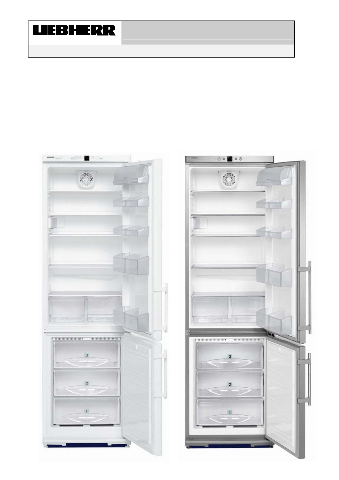
NoFrost combined refrigerator-freezers
Page 1/18 02200600SI_gb.doc
Page 2
Service Information No. 02/2006 (Version 01) CN(es) ..03
Contents
1.0 Operating and control elements 3
2.0 Functions at a glance 3
3.0 Description of the appliance 4
3.1 Refrigerator compartment: 4
3.2 NoFrost freezer compartment 4
3.3 Refrigerating circuit 5
4.0 Control and functional components 6
4.1 Refrigerator compartment 6
4.2 NoFrost freezer compartment 7
5.0 Refrigeration circuit 8
5.1 Refrigerator compartment 8
5.2 NoFrost freezer compartment 8
6.0 Special features 9
6.1 Solenoid valve 9
6.1.1 Electrical actuation of the solenoid valve 9
6.1.2 Schematic diagrams solenoid valve 9
7.0 Assembly instructions 9
7.1 Refrigerator compartment 9
7.1.1 Evaporator sensor 9
7.1.2 CN(es) 3303 / 3803 from -21 fan 10
7.2 NoFrost freezer compartment 11
7.2.1 Air sensor, evaporator module and fan module 11
7.2.2 Temperature fuse, evaporator sensor and defrosting heater 12
7.2.3 Fan and reed PCB 12
7.2.4 Water drain valve 13
7.3 Solenoid valve 13
7.4 Integral PCB 14
8.0 Technical data 16
8.1 Refrigerator compartment 16
8.2 NoFrost freezer compartment 16
9.0 Service menu 17
9.1 NoFrost freezer compartment defrosting "-15°C LED" (evaporator must be cold) 17
9.2 Demo mode 17
9.3 Service mode 18
10.0 Table of error codes 18
Page 2 of 18
Page 3
Service Information No. 02/2006 (Version 01) CN(es) ..03
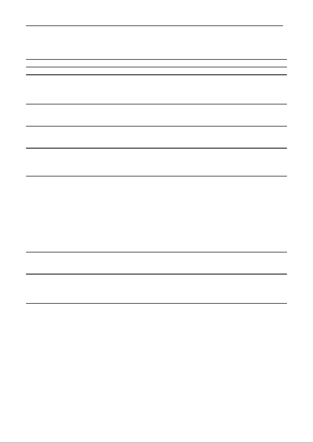
1.0 Operating and control elements
Refrigerator compartment Freezer compartment
1 : Control button,
ON / OFF, temperature setting.
3 : Temperature setting display refrigerator
compartment
2 1
2.0 Functions at a glance
3
4
2 : Alarm OFF button for audible alarm
button lit = active alarm for too high temperature in
freezer compartment.
4 : Temperature setting display freezer
compartment
5 : SuperFrost button,
button lit = function switched on.
6 : Control button,
ON / OFF for the entire appliance (refrigerator
and freezer compartment), temperature setting.
6 5
Control:
Temperature display:
Temperature alarm:
Door alarm:
Fan:
Defrosting:
Interior light:
SuperCool:
SuperFrost:
Service menu:
Electronic control system
Set value display
Refrigerator compartment: no
Freezer compartment: visual and audible
Refrigerator compartment: audible
Freezer compartment: audible
Refrigerator compartment: no CN(es) 3303 / 3803 from -20
Refrigerator compartment: yes CN(es) 3303 / 3803 from -21
Freezer compartment: yes
Refrigerator compartment: automatic
Freezer compartment: automatic
Refrigerator compartment: yes
Freezer compartment: no
no
Automatic (time-controlled)
Start by button combination
Refrigerating system:
1 standard compressor with solenoid valve
Page 3 of 18
Page 4
Service Information No. 02/2006 (Version 01) CN(es) ..03
t
3.0 Description of the appliance
The CN(es) ..03 is a combined refrigerator-freezer with a NoFrost freezer compartment. The appliance has a
compressor. The refrigerator and freezer compartment evaporator is activated via a bi-stable solenoid valve.
Both evaporators are connected in series (see 3.3 Schematic diagram: Refrigerating circuit).
Therefore the refrigerator compartment can be operated only in conjunction with the freezer compartment.
However, it is possible to operate the freezer compartment on its own.
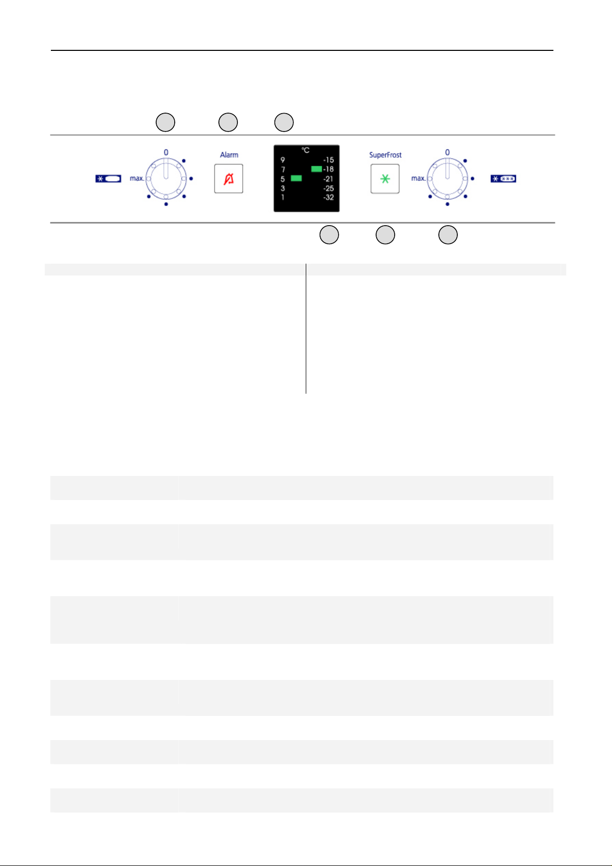
3.1 Refrigerator compartment:
The refrigerator compartment is equipped with a foamed-in evaporator and an evaporator sensor. The sensor is
separately replaceable.
The evaporator sensor is responsible for switching off the refrigeration, sees to the defrosting of the refrigerator
compartment evaporator and switches the refrigeration on.
A fan is optionally activatable for even temperature distribution.
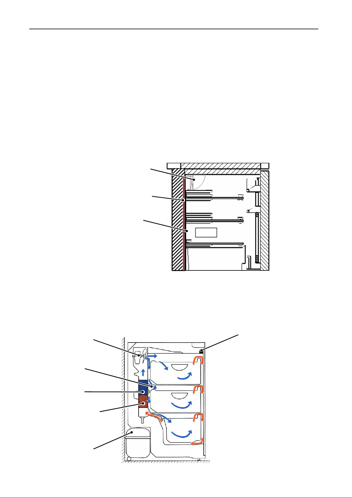
3.2 NoFrost freezer compartment
The freezer compartment is equipped with a NoFrost rear wall evaporator module, fan module, air sensor and
evaporator sensor. Both sensors are separately replaceable. The defrosting phases are initiated by way of the
electronic control system, taking compressor running time and door openings into account.
Fig. 3.2 Schematic diagram NoFrost freezer compartment
Evaporator
Evaporator sensor
Fan
Air sensor
Compressor
Only CN(es)
3303/3803 from 21 wi
h fan
Foamed-in
rear wall evaporator
Evaporator sensor
Fig. 3.1 Schematic diagram
refrigerator compartment
Reed switch
Page 4 of 18
Page 5
Service Information No. 02/2006 (Version 01) CN(es) ..03
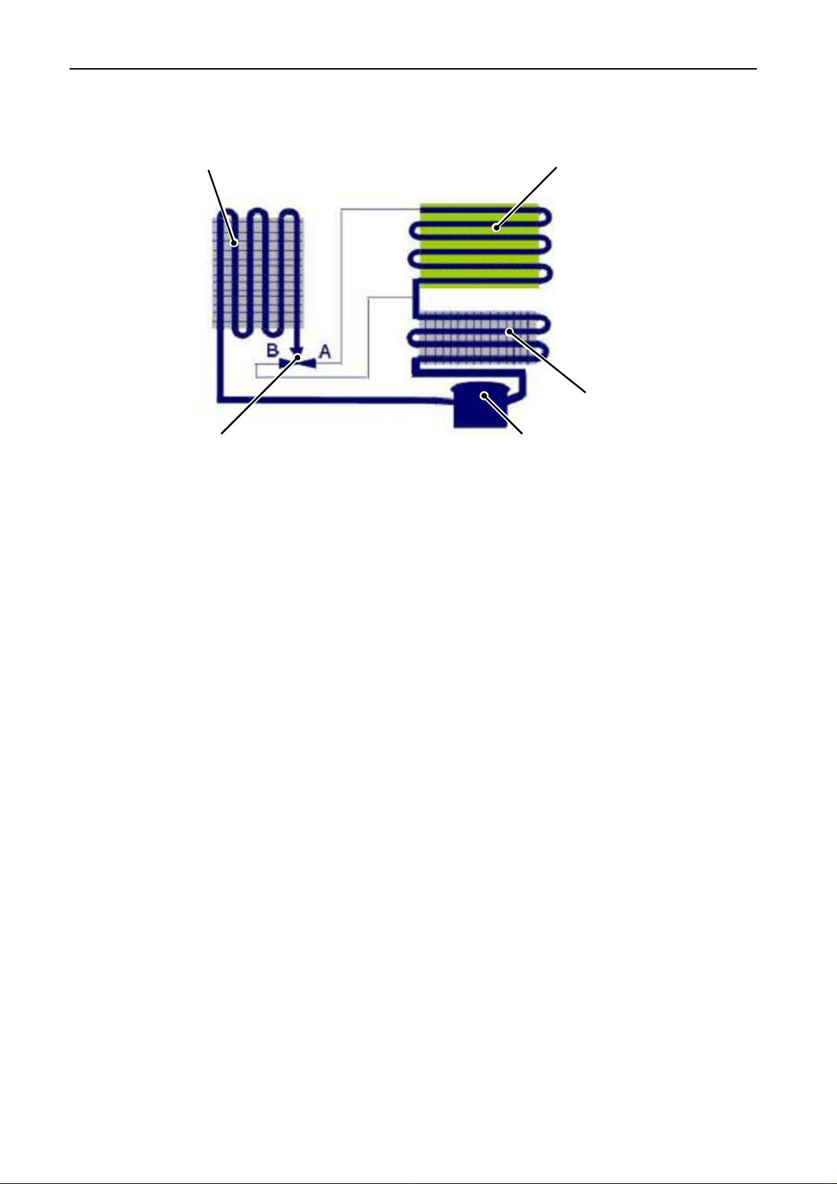
3.3 Refrigerating circuit
Fig. 3.3 : Schematic diagram refrigerating circuit
Condenser
Solenoid valve
Refrigerator
compartment evaporator
Freezer compartment
Compressor
Page 5 of 18
Page 6

Service Information No. 02/2006 (Version 01) CN(es) ..03
4.0 Control and functional components
4.1 Refrigerator compartment
Electronic control system:
Setting range:
Display range:
Door alarm:
Interior light:
Reed PCB:
Evaporator sensor:
Series 3 electronic control system: integral PCB.
+9°C / +7°C / +5°C / +3°C / +1°C
9°C / 7°C / 5°C / 3°C / 1°C * (set value display)
When: After the refrigerator compartment door has been open for 60 secs.
Audible: 3 beeps.
Position: Inside left.
Function: - Is switched on as soon as refrigerator compartment door is opened.
- Is switched off after door has been open for 15 minutes.
Position: In front panel.
Function:- Switches the interior light on when the door is opened.
- Switching contact for door alarm.
Only CN(es) 3303 / 3803 from -21
- Switches the fan (if activated) off when the door is opened.
Position: Behind cover, on rear wall, level with light housing.
Function:- Refrigerator compartment evaporator sensor or freezer compartment
air sensor switches the compressor ON.
- Refrigerator compartment evaporator sensor and freezer
compartment air sensor switch the compressor OFF.
- Switches solenoid valve to position A (refrigerator + freezer
compartment)
- Switches solenoid valve to position B when the switch-off valve is
reached (freezer compartment only)
Fan:
CP(es) 3303/3803 from
Index -21
Defrosting:
Compressor:
Position: At the centre back of t he ceiling of the compartment liner.
Function:ON: - Fan switch ON and
- compressor ON and
- refrigerator compartment door closed and
- solenoid valve at position A (refrigerator + freezer
compartment)
OFF: - Fan switch OFF or
- compressor OFF or
- refrigerator compartment door open or
- solenoid valve at position B (freezer compartment)
During start-up the fan is activated only from an evaporator sensor temperature of +12°C and colder.
Automatic during standstill phase of the compressor. Automatic when solenoid valve is set to position B (freezer compartment).
Function: ON: - Refrigerator compartment evaporator sensor switch-
on value or
- freezer compartment air sensor switch-on value.
Note: On-delay time (8 mins.) must have elapsed.
OFF: - Refrigerator compartment evaporator sensor switch off value and
- freezer compartment air sensor switch-off value
Page 6 of 18
Page 7

Service Information No. 02/2006 (Version 01) CN(es) ..03
4.2 NoFrost freezer compartment
Electr. control system:
Setting range:
Display range:
Temperature alarm:
Door alarm:
Reed PCB:
Fan:
See 4.1 Refrigerator compartment.
-15°C / -18°C / -21°C / -25°C / -32°C
-15°C / -18°C / -21°C / -25°C / -32°C (set value display)
When: measured sensor temperature is 7K warmer than set value
(e.g. set value: -18°C, actual value for 90 min. at 11°C Æ alarm)
SuperFrost alarm value: Actual value = -10°C
Audible: 4 beeps (suppressed for 90 min. during start-up)
During startup the alarm LED is permanently lit (acknowledged alarm), the
audible alarm is switched off.
After defrost end the alarm is suppressed for 30 min.
When: With open freezer compartment door after 60 secs.
Audible: 3 beeps.
Position: In freezer compartment fan housing.
Function: - Turns off the fan when the door is opened.
- Switching contact for door alarm.
Position: At top in middle of freezer compartment.
Air sensor:
Evaporator sensor:
Evaporator heater:
Function: ON: - compressor on and
- freezer compartment door closed and
- evaporator sensor switch-on value reached.
Switch-on value evaporator sensor:
a) During start-up / after defrosting phase: -25°C.
b) in normal operation 2K colder than freezer compartment air sensor.
OFF: - Compressor off or
- freezer compartment door open.
Position: In sensor holder on air duct cover.
Function: - Freezer compartment evaporator sensor or refrigerator
compartment air sensor switches the compressor ON.
- Freezer compartment air sensor and refrigerator compartment
evaporator sensor switch the compressor OFF.
Position: Inserted into lamellar evaporator.
Function: - Ends the defrosting phase.
- Switches the freezer compartment fan on.
Only one heater for evaporator and defrost water drain channel.
Safety temperature restrictor, connected in series with heater.
Activated via electronic control system (see Defrosting).
Page 7 of 18
Page 8

Service Information No. 02/2006 (Version 01) CN(es) ..03
Defrosting:
Water drain valve:
SuperFrost:
Compressor:
The defrosting phase is started:
- During start-up after 6 hours cumulative compressor running time.
- After a cumulative compressor running time of 12 to a maximum of
60 hours, depending on the number/duration of the door openings.
When the defrosting phase begins, the compressor and the fan are switched
off and the defrosting heater is switched on.
The defrosting heater remains switched on until:
- the evaporator has reached +5°C or
- 50 minutes have elapsed.
After the end of the heating phase, the compressor is switched on with a
10 minute delay.
If the SuperFrost function is activated during the defrosting phase, this will not
interrupt defrosting.
Foamed in water drain, water drain valve can be drawn off for cleaning
purposes
(see 7.2.4 Assembly instructions water drain valve).
Cooling of freezer compartment to -37°C (65 hours).
See 4.1 Refrigerator compartment -compressor-
5.0 Refrigeration circuit
5.1 Refrigerator compartment
Evaporator:
Injection point /
flow sequence:
Solenoid valve:
Compressor:
Rear wall evaporator, foamed in.
Solenoid valve in position A (refrigerating + freezing):
Introduction of refrigerant in refrigerator compartment evaporator top left, then
transition to freezer compartment evaporator.
2 capillary tubes (long coil refrigerator compartment, short coil freezer
compartment).
1 standard compressor.
On-delay time of 8 mins.
5.2 NoFrost freezer compartment
Evaporator:
Injection point:
Solenoid valve:
Lamellar evaporator, in the rear wall of the freezer compartment.
The defrosting heater is attached directly to the evaporator.
Solenoid valve in position B (freezing):
Top left on lamellar evaporator.
See 5.1 Refrigerator compartment -solenoid valve-.
Compressor:
Frame heater:
See 5.1 Refrigerator compartment -compressor-.
Foamed-in liquid heater in area of freezer compartment door.
Page 8 of 18
Page 9

Service Information No. 02/2006 (Version 01) CN(es) ..03
6.0 Special features
6.1 Solenoid valve
6.1.1 Electrical actuation of the solenoid valve
With this model a bi-stable solenoid valve is used. This means that after actuation the solenoid valve maintains
the respective switching state.
To sum up:
To check actuation of the solenoid valve, we recommend using the service menu (see 9.3 Service mode "L" ).
Here the switching of the solenoid valve can be clearly heard.
6.1.2 Schematic diagrams solenoid valve
Freezer compartment addressed Refrigerator compartment and freezer
compartment addressed
Fig. 6.1.2 / 1 Fig. 6.1.2 / 2
7.0 Assembly instructions
7.1 Refrigerator compartment
7.1.1 Evaporator sensor
Evaporator sensor: - Undo scre w of the evaporator sensor cover (see Fig. 7.1.1/ 1)
- Remove evaporator sensor cover.
- Undo marked screw for evaporator sensor mount (see Fig. 7.1.1/ 2).
- Disengage evaporator sensor.
Fig. 7.1.1/ 1
Evaporator sensor cover
Evaporator sensor
Fig. 7.1.1/ 2
Page 9 of 18
Page 10

Service Information No. 02/2006 (Version 01) CN(es) ..03
7.1.2 CN(es) 3303 / 3803 from -21 fan
Fan: - Undo fastening screws of the fan (see Fig. 7.1.2/ 1).
- Pull off connecting cable, unlock fan switch (see Fig. 7.1.2/ 2) and press out
forwards.
- Remove air guide plate from fan housing (see Fig. 7.1.2/ 3).
- Remove fan from motor mount.
- Cable routing in fan housing (see Fig. 7.1.2/ 5) for installation.
Fig. 7.1.2/ 1 Fastening screws
fan
Fig. 7.1.2/ 3 Air guide plate
Fig. 7.1.2/ 5 Cable routing
Fan switch
Fig. 7.1.2/ 2 Fan switch
Fig. 7.1.2/ 4 Fan motor
Page 10 of 18
Page 11

Service Information No. 02/2006 (Version 01) CN(es) ..03
g
g
7.2 NoFrost freezer compartment
7.2.1 Air sensor, evaporator module and fan module
Air sensor: Engaged in sensor holder on air duct cover.
Evaporator module: Remove drawers and glass shelves in freezer compartment, detach air sensor, un-
screw the Torx screws marked in the picture with an arrow and remove the rear
wall. By releasing the plastic screw arrow 1, the evaporator module can be lifted
and drawn forwards.
Fan module: Undo plastic screws arrow 2 and 3. Also undo Torx screws arrows 4 and 5,
then the fan module can be swung out.
Air duct panel
Air sensor
2
4
5
3
1
Fi
. 7.2.1/ 1 Freezer compartment with air duct
Fi
. 7.2.1/ 2 Freezer compartment without air
Page 11 of 18
Page 12

Service Information No. 02/2006 (Version 01) CN(es) ..03
7.2.2 Temperature fuse, evaporator sensor and defrosting heater
Temperature fuse: The temperature fuse can be replaced separately with a conversion kit.
The conversion kit comprises: - 1 temperature fuse
- 2 pressure connectors
- 2 shrinkdown tubings
Please note:
Always attach the compression joint to the red and blue lines of the temperature
fuse. As soon as the white line of the defrosting heater is cut, the defrosting heater
is destroyed.
Evaporator sensor: Is inserted into lamellar evaporator.
Defrosting heater: Is clipped into the evaporator fins. Can be replaced if defective.
Temperature fuse
Evaporator sensor
Fig. 7.2.2 Evaporator module
7.2.3 Fan and reed PCB
Fan: The fan is inserted in the plastic module with rubber buffers. The line is equipped
with a removable plug.
Reed PCB: The reed switch is inserted in the fan module.
Fig. 7.2.3/ 1 Fan module
Reed PCB
Fig. 7.2.3/ 2 Fan module with reed PCB
Page 12 of 18
Page 13

Service Information No. 02/2006 (Version 01) CN(es) ..03
7.2.4 Water drain valve
The water drain valve is accessible from the compressor niche. It is situated just above the
evaporation tray of the compressor.
Fig. 7.2.4 Water drain valve
7.3 Solenoid valve
Refrigerator compartment
Dryer
Freezer compartment
Refrigerating connections are printed on the solenoid valve cover:
The magnets must repel each other.
Permanent magnets
Attention: insert correctly
KS: Refrigerator compartment capillary
GS: Freezer compartment capillary
A
C
Fig. 7.3 Solenoid valve
A
C
B
B
Page 13 of 18
Page 14

Service Information No. 02/2006 (Version 01) CN(es) ..03
g
g
7.4 Integral PCB
Covers: Disengage covers.
Fig. 7.4/ 1
Front panel: Undo screws of front panel.
Fi
. 7.4/ 3
Sensor cable: Detach sensor cable from cable clamp.
Fig. 7.4 / 5
PCB carrier: Disengage PCB carrier of the integral PCB from the front panel at the marked points,
in the order indicated.
Fi
3
. 7.4 / 6
2
Fig. 7.4/ 2
Fig. 7.4 / 4
1
Page 14 of 18
Page 15

Service Information No. 02/2006 (Version 01) CN(es) ..03
g
After unlocking, swing the PCB carrier out of the front panel in the arrow direction.
Fi
. 7.4 / 7
Integral PCB: Disengage integral PCB from PCB carrier at the marked points.
Fig. 7.4/ 8
Page 15 of 18
Page 16

Service Information No. 02/2006 (Version 01) CN(es) ..03
8.0 Technical data
8.1 Refrigerator compartment
Interior light:
Wattage: 25 watts
Voltage: 230 volts
Socket: E14
Fan:
Only CN(es)
3303/3803
from -21
Sensor values:
Wattage: 5.8 watts
Voltage: 230 volts
Speed: 1700 rpm
Evaporator sensor
Temperature °C Resistance value kOhm
+35 3.1
+30 3.8
+25 4.7
+20 5.9
+15 7.3
+10 9.3
+5 11.9
0 15.3
-5 19.8
-10 25.9
-15 34.1
-20 45.3
-25 60.8
-30 82.3
-35 112.8
8.2 NoFrost freezer compartment
Fan:
Solenoid valve:
Defrosting heater:
Protection against
overheating:
Sensor values:
Wattage: 4 watts
Voltage: 230 volts
Speed: 2150 rpm winding not measurable through connections
(electronic fan)
Voltage: 230 volts (actuated with half-waves)
Resistance: 2.8 kOhm, at +20°C
Wattage: 132 watts
Voltage: 230 volts
Current: 0.55 amperes
Resistance: 404 ohms, (+20°C)
- +93°C, in series with defrost heater
- Cannot be reactivated and, once actuated, it has to be replaced
Air and evaporator sensor See 8.1 Refrigerator compartment.
Page 16 of 18
Page 17

Service Information No. 02/2006 (Version 01) CN(es) ..03
9.0 Service menu
The service menu may be used only by customer service technicians.
Start conditions:
9.1 NoFrost freezer compartment defrosting "-15°C LED" (evaporator must be
cold)
• Keep SuperFrost depressed and turn freezer compartment control button from “0“ to the right until
SuperFrost LED flashes.
• Set control button so that -15°C LED is lit, SuperFrost flashes.
• Press SuperFrost, the appliance is now in defrost mode.
• The defrosting phase is started.
• The defrosting phase is complete as soon as the evaporator reaches +5°C or after 50 minutes.
• The appliance automatically switches back to normal operation.
• The defrosting phase can be ended prematurely by switching the appliance off and on again.
9.2 Demo mode
• Keep SuperFrost depressed and turn freezer compartment control button from “0“ to the right until
SuperFrost LED flashes.
• Now turn until the –18°C LED is lit.
• -18°C LED is lit = demo mode is deactivated.
To activate the demo mode, press SuperFrost.
• -18°C LED flashes = demo mode is activated.
To deactivate the demo mode, press SuperFrost.
• If no change is wanted, do not press SuperFrost, but set the control button to "0".
• When the demo mode is active, the compressor is not addressed.
Attention: The demo mode cannot be deactivated by power OFF/ON. This is possible only via the
Both rotary buttons have to be set to “0“.
service menu.
Page 17 of 18
Page 18

Service Information No. 02/2006 (Version 01) CN(es) ..03
9.3 Service mode
• Keep SuperFrost depressed and turn freezer compartment control button from “0“ to the right until
SuperFrost LED flashes.
• Now turn until the –21°C LED is lit.
• Press SuperFrost, service mode is active.
• Open and close both doors. LEDs light up in groups.
• Turn both control buttons from "0" to "max". LEDs light up in groups.
• Press each button. LEDs light up in groups.
• All the loads can be addressed individually using the SuperFrost button.
SuperFrost LED flashes alternately with
o 9°C / -15°C LED: No load addressed
o -18°C LED: Compressor ON, solenoid valve in position B (freezer compartment)
o 7°C LED: Compressor ON, solenoid valve in position A (refrigerator compartment
+ freezer compartment)
o -21°C LED: Fan freezer compartment
o -25°C LED: Defrost heater freezer compartment
o 1°C / -32°C LED: Light ON
o 5°C LED: Fan ON, when fan switch is set to ON
• End: Set both control buttons to "0".
10.0 Table of error codes
Error code
SFLED
2 Hz in synchro-
nism with
3°C LED
SFLED
2 Hz in synchro-
nism with
-15°C LED
SFLED
2 Hz in synchro-
nism with
-18°C LED
The audible alarm can be switched off with the alarm OFF button.
Audible
alarm
yes no
yes no
yes no
Alarm LED Defective component Emergency operation
Evaporator sensor for
refrigerator compartment
Freezer compartment air
sensor
Evaporator sensor, freezer
compartment
Refrigerator compartment is
cyclically controlled
Compressor continuous
operation
Compressor continuous
operation
Page 18 of 18
 Loading...