

Page 1

Wheel Loaders L 524 – L 542
Tipping load, articulated: 16,535 lb – 22,485 lb
New
Generation
Page 2

L 524
L 528
L 538
Tipping load, articulated:
Bucket capacity: 2.7 yd³
Operating weight: 22,930 lb
Engine output: 121 HP(I)/90 kW
16,535 lb
L 542
Tipping load, articulated:
Bucket capacity: 3.7 yd³
Operating weight: 29,540 lb
Engine output: 161 HP(I)/120 kW
22,485 lb
Tipping load, articulated:
Bucket capacity: 3.0 yd³
Operating weight: 24,030 lb
Engine output: 134 HP(I)/100 kW
18,740 lb
Tipping load, articulated: 20,945 lb
Bucket capacity: 3.4 yd³
Operating weight: 28,220 lb
Engine output: 154 HP(I)/115 kW
2 L 524 – L 542
Page 3

Economy
The Liebherr driveline with Liebherr Power Effi ciency (LPE)
reduces wheel loader fuel consumption by 25 % or more when
compared to conventional travel gears!
Performance
The Liebherr driveline allows for optimal positioning of the diesel
engine. In this wheel loader class the diesel engine is rotated 90°
and mounted transverse to the direction of travel. Compared
to conventionally driven wheel loaders, the operating weight is
much lower, the tipping load is higher, and more material can be
moved each operating hour.
Reliability
All the materials used in the Liebherr wheel loaders have passed
extensive tests to ensure that they meet Liebherr’s exacting
standards even in the toughest conditions. The advanced
concept and proven quality make Liebherr wheel loaders the
benchmark of reliability.
Comfort
The ultra-modern cab design with advanced ergonomics
continuously variable Liebherr driveline for uninterrupted
tractive force, optimum weight distribution and easy service
access lead to extraordinary overall comfort.
L 524 – L 542 3
Page 4
35
30
25
20
15
n=?
Lower fuel consumption
Effi ciency behaviour without LPE
Favorable
• Up to 25 % less fuel consumption
5
8'2"
B
65'7"
T ~ 35 sec.
A
4
3
2
1
when compared to conventionally
driven machines.
• The Liebherr wheel loaders
demonstrate their fuel effi ciency
in the Liebherr standard Normtest.
Pressure
Effi ciency behaviour with LPE
rpm rpm
4 L 524 – L 542
L0083
Working point
Pressure
Unfavorable
Page 5

Economy
The Liebherr driveline with Liebherr Power Effi ciency (LPE) reduces wheel loader fuel
consumption by 25 % or more when compared to conventional travel gears!
Low operating costs
Minimum costs,
high handling capacity
When it comes to economy, conventional wheel loaders
are no match for Liebherr machines, mainly due to the
following factors:
− Low fuel consumption thanks to higher effi ciency and
low operating weight. Thanks to the newly developed
Liebherr Power Effi ciency system the generation
Tier 4i wheel loaders L 524 – L 542 use up to 8 % less
fuel compared to their predecessors.
− Practically no brake wear thanks to the hydraulic braking
action of the driveline; this ultimately reduces repair
costs.
− Reduced tire wear due to continuous traction control.
Depending on the working conditions, there is up to
25 % less wear.
Liebherr Power Ef fi ciency (LPE)
• The newly developed system known
as Liebherr Power Effi ciency (LPE)
optimizes the interaction between
the drive components. It optimizes
the position of the working point in
the characteristic map with regard
to the degree of effi ciency.
• LPE saves up to an additional 8 %
in fuel compared to wheel loaders
where the system is not used.
Active environmental protection
Economical use
of resources
Low noise emission
The reduction in fuel lowers emissions, thus actively
protecting resources:
0.3 gal of fuel produces up to 7 lb of carbon dioxide (CO
By saving up to 1.3 gal per operating hour, up to 33,070 lb
less CO
2
is produced in 1,000 operating hours. Not only
are operating costs reduced but the environment also
benefi ts from the drastically reduced emissions.
The innovative driveline concept means much lower noise
emission – Liebherr wheel loaders are signifi cantly quieter
in operation.
Reduced tire wear
• The tractive force can be adjusted
continuously. This stops wheel spins
and reduces tire wear by up to 25 %.
Reduced brake wear
• Even under the toughest working
conditions, the Liebherr travel drive
always brakes hydraulically. The
mechanical service brake only acts
as a support and is therefore subject
to hardly any wear.
2
).
L 524 – L 542 5
Page 6

6 L 524 – L 542
Liebherr driveline
• Optimum weight distribution
thanks to transverse installation
of the diesel engine.
L0073
• The diesel engine as well as the
variable displacement pumps
mounted on the engine act as
counterweight, therefore allowing
higher tipping loads at low
operating weight.
• Compact design improves
visibility in all directions.
L0074
Page 7

Performance
The Liebherr driveline allows for optimal positioning of the diesel engine. In this wheel
loader class the diesel engine is rotated 90° and mounted transverse to the direction of
travel. Compared to conventionally driven wheel loaders, the operating weight is much
lower, the tipping load is higher, and more material can be moved each operating hour.
Higher performance, lower weight
Higher productivity
Ultra modern Liebherr driveline
Innovative technology
Flexibility puts them ahead
An all-purpose loader
Power All-Rounders
for industry
The combination of the Liebherr driveline and the unique
position of the diesel engine allows for higher tipping loads at low
operating weight. This leads to signifi cantly higher productivity
since there is no need for unnecessary counterweight.
Tractive force and speed are automatically adjusted to the
requirements of the operator without shifting. There is no need
for a mechanical reverse gear because the travel direction is
changed hydraulically.
The parallel linkage is available as an alternative to the standard
Z-bar linkage, at no additional cost. The parallel linkage features
a parallel guide arrangement and high torque in the upper lifting
range - ideal properties for larger and heavier attachments
as well as transporting heavy loads. With its parallel linkage
Liebherr offers a continuous and uniform solution for industrial
operations over the entire range of all-round loaders. With their
compact design, Liebherr wheel loaders can maneuver quickly
and effi ciently - the best choice for high handling capacities.
The new generation Tier 4i all-round wheel loader models have
been specifi cally developed for industrial use in terms of their
performance and stability and ensure even higher productivity
and effi ciency. In addition to increasing the engine performance,
the tipping loads of the whole range have been increased.
Furthermore the steel structure has been reinforced and the
hydraulic system‘s performance enhanced. That, together with
the wide range of equipment available makes these all-round
loaders the perfect solution for all industrial uses.
Conventional travel gear
• Longitudinally mounted diesel
engine moves the center of gravity
further forward.
• Much more additional
counter weight is needed to maintain
stability and to increase the tipping
load.
• This leads to high operating weight
and poor visibility.
L 524 – L 542 7
An all-purpose loader
• The choice between parallel (P) and
Z-bar linkage means that the loader
can always be confi gured to suit
the customer’s specifi c tasks: P for
industrial use, Z for conventional
material handling.
Page 8

8 L 524 – L 542
Liebherr driveline
• The Liebherr driveline consists
of two hydraulic motors, which
accelerate the loader continuously
from a standstill to maximum
speed, either forwards or in
reverse – without a manual gear
shift and a reversing gear unit.
Page 9

Reliability
All the materials used in the Liebherr wheel loaders have passed extensive tests to ensure
that they meet Liebherr’s exacting standards even in the toughest conditions. The advanced
concept and proven quality make Liebherr wheel loaders the benchmark of reliability.
Reliable Liebherr driveline
Fewer components
Controlled cooling
The intelligent
answer
T
he Liebherr driveline includes a self-locking hydraulic
brake, which means the additional wet brake discs are
wear-free since there is no need for a reversing gear unit.
There are fewer components needed, which minimizes the
number of parts susceptible to wear.
The cooling fan is driven independently from the diesel
engine and produces only the cooling air output which is
actually required. Heat sensors ensure reliable control. If
overheating should occur, the wheel loader automatically
shifts down to fi rst travel speed range. The reduced power
consumption protects the engine from overheating. At the
same time, the fan speed is increased to maximum output,
thus preventing the engine from overheating.
Cooling system
• The radiator is installed on the rear
section of the vehicle, between the
diesel engine and the cabin. Cooling
air is drawn in directly behind the
cabin and blown out upwards at
the rear. The fan speed is varied
automatically by heat sensors that
determine the amount of cooling
needed.
• The reversible fan drive is
a standard feature.
Components meet manufacturer’s quality
standards
Everything from
a single source
Optimized engine
technology
Main components such as hydraulic cylinders and
electronics are developed and manufactured by Liebherr
to ensure the highest quality standards. Liebherr Wheel
Loaders are carefully designed down to the smallest detail
to provide customers with the perfect machine solution to
match the application-specifi c demands while achieving
maximum productivity and longevity.
As well as further developments towards greater
environmental compatibility, the new generation of diesel
engines have been optimized in a number of other respects.
In addition to Common Rail technology a diesel particle
fi lter signifi cantly reduces exhaust emissions. With active
regeneration, in most operational circumstances this
fi ltration process ensures effi cient, uninterrupted work.
Diesel engine
• Common Rail technology optimizes the
combustion process and reduces emissions.
• Further reduction of particle emissions due to
the diesel particle fi lter with oxidation catalytic
converter. Active regeneration ensures effi cient,
uninterrupted work.
• Proactive intervention of Liebherr Power
Effi ciency (LPE) in the engine management
system increases effi ciency.
L 524 – L 542 9
Page 10

10 L 524 – L 542
Liebherr control lever
•
The multi-function Liebherr control lever is used
to manage all travel and working movements of
the wheel loader. This ensures the operator’s left
hand always remains on the steering wheel and
therefore increases overall safety. The operator
controls the following functions with his right hand:
– Raise and lower attachment
– Fill and dump the bucket
– Automatic bucket return to dig
– Change of travel direction with
simultaneous travel start
–
Auxiliary control buttons for additional hydraulic functions
Page 11

Comfort
The ultra modern cab design with advanced ergonomics, continuously variable Liebherr
driveline for uninterrupted tractive force, optimum weight distribution and easy service
access lead to extraordinary overall comfort.
First-class cab design
Comfor t cab
Liebherr
control lever
Liebherr driveline
Continuously
variable
transmission
Liebherr Power
Effi ciency
The spacious and ergonomically designed Liebherr
operator’s cab provides a wide view to the working area
to ensure safety. All tool controls and displays have been
carefully arranged for ease of operation and to maintain a
comfortable work environment during working shifts.
All the working and travel functions are operated precisely
from a single control lever. This ensures accurate and safe
handling, and the left hand always remains on the steering
wheel. Jobsite safety is increased.
The Liebherr driveline allows continuous adjustment of
acceleration in all speed ranges, without noticeable gear
shifting or interruption in tractive force.
Liebherr Power Effi ciency (LPE) optimizes the effi ciency and
effectiveness of the travel drive, which places less stress
on the components. The operator actuates the accelerator
pedal in the usual way to obtain the full power performance
desired. An electrical signal is transmitted from the pedal to
the software of the machine which automatically calculates
the most effi cient driving command. This is possible due
to the proactive intervention into the engine management
system. The usual high performance as well as the drive
behavior of the machine as a whole remain unchanged. If
anything, the response is even faster.
LIKUFIX
• Equipment with hydraulic functions
can be changed from the cab in a
matter of seconds.
• No need to climb out and connect
everything mechanically: both
picking up the equipment and
connecting the hydraulic hoses
is fully automatic - safe and with
no oil leaks.
• The convenience and time savings
speak for themselves: LIKUFIX
yield a consistent standard of high
performance, reliability and quality.
LIKUFIX
Time savings
and productivity
LI KUFIX is quick-c hange syste m c omb ined w ith an automat ic
hydraulic coupling system developed in-house by Liebherr.
This option is available for Liebherr wheel loaders and
excavators. LIKUFIX allows the quick exchange between
attachments and all hydraulic connections safely from inside
the cab with a simple press of a button.
Powerful air-conditioning system
• The air-conditioning system comes standard
on all-round wheel loaders providing the
greatest operator comfort for increased
productivity.
• The air fl ow is controlled at 4 different levels –
an automatic air-conditioning system is
available as an option.
– Air fl ow in the feet area
– Defroster
– Air fl ow in the head area
– Air fl ow in the body area
L 524 – L 542 11
Page 12

12 L 524 – L 542
Service accessibility
• The transverse engine facilitates maintenance.
Opening a single cover allows safe and
convenient access to all maintenance points
from ground level.
Page 13

Service/Maintenance
LiDAT
Effi cient management
Diagnostic and remote maintenance
Consistent monitoring
With LiDAT, Liebherr’s own data transmission and positioning
system, you can manage, monitor and control your entire fl eet
effi ciently. LiDAT allows you to access machine data records,
perform data analysis, and review service records within the
fl eet management system. All machine data can be accessed
at anytime simply, via the internet. The system provides you
with comprehensive documentation about operating hours,
increased availability through shorter downtimes, and faster
suppor t from the manufacturer. There is al so faster detection of
stress and overloading, which extends the machine’s service
life to provide more effi cient planning for your company. The
LiDAT system comes standard on the L 524 – L 542 wheel
loaders and it includes a one-year free trial.
The electronic system of the all-round loaders has been
designed just as the large size class. Due to this fact, the allround loaders offer an extended range of options such as the
convenient touchscreen, the integral rear-view monitoring
camera and the newly developed Liebherr weighing device.
The new electronic system permits standard diagnostic and
remote maintenance over the range of machines providing a
clear benefi t in their everyday operations.
Service accessibility
Easy maintenance
With the unique position of the diesel engine, Liebherr wheel
loaders provide outstanding accessibility for maintenance.
The positioning of the cooling system directly behind the
cab results in less contamination, which in turn reduces
maintenance and cleaning; a clear benefi t which saves time
and money.
All service points can be reached from ground level for
routine maintenance. Cleaning of the cooling system is
carried out while positioned on the machine, anti-slip step
surfaces and strong handrails in the access area ensure high
safety standards.
Electronics
• Standard diagnostic and remote maintenance
• Full version of LiDAT including
a one-year free trial.
• Optional touchscreen
• Optional Liebherr rear-view monitoring
camera and weighing device - integrated
in the color touchscreen
L 524 – L 542 13
Page 14

Technical Data
L 524 L 528 L 538 L 542
Diesel engine
Design
Cylinder inline
Fuel injection process ������ electronic Common Rail high-pressure injection
Max. output according to
SAE J1995
at RPM 2,000 2,200 2,000 2,000
Max. torque
at RPM 1,600 1,600 1,600 1,600
Displacement
Bore/Stroke
Air cleaner system
Electrical system
Operating voltage
Battery
Alternator
Starter
Engine
�����������������������
�������������������������
�����������������
���������
HP(I)/kW 121/90 134/100 154/115 161/120
��������������
��������������
�����������������
�����������������
���������������������
������������������
�����������������
lb ft 354 363 454 476
����������
V/A 24/100 24/100 24/100 24/100
V/HP(I) 24/10.5 24/10.5 24/10.5 24/10.5
4045HFL92 4045HFL93 4045HFL93 4045HFL93
water-cooled with exhaust turbo charging, externally
cooled exhaust gas recirculation and diesel particulate
filter
4 4 4 4
in³ 275 275 275 275
in 4.2”/5.0” 4.2”/5.0” 4.2”/5.0” 4.2”/5.0”
Dry air filter with main and safety element,
pre-cleaner, service indicator on the display
V 24 24 24 24
Ah 2 x 135 2 x 135 2 x 135 2 x 135
The exhaust emissions are below the limits in stage IIIB / Tier 4i.
L 524
738
664
590
516
443
369
295
Torque (lb ft)
221
148
74
0
800 1,000 1, 200 1,40 0 1, 60 0 1,8 00 2,000 2,20 0 2,400
rpm
Torque
Output
180/241
150/201
120/161
90/121
60/80
30/40
0
L0010
738
664
590
516
443
369
Output (kW/HP)
295
Torque (lb ft)
221
148
L 528
74
0
800 1,000 1, 200 1,40 0 1, 60 0 1,8 00 2,000 2,20 0 2,400
rpm
Torque
Output
180/241
150/201
120/161
90/121
60/80
30/40
0
L0 011
Output (kW/HP)
738
664
590
516
443
369
295
Torque (lb ft)
221
148
74
0
800 1,000 1, 200 1,40 0 1, 60 0 1,8 00 2,000 2,20 0 2,400
14 L 524 – L 542
L 538
rpm
Torque
Output
180/241
150/201
120/161
90/121
60/80
30/40
0
L0012
738
664
590
516
443
369
Output (kW/HP)
295
Torque (lb ft)
221
148
L 542
74
0
800 1,000 1, 200 1,40 0 1, 60 0 1,8 00 2,000 2,20 0 2,400
rpm
Torque
Output
180/241
150/201
120/161
90/121
60/80
30/40
0
L0013
Output (kW/HP)
Page 15

Technical Data
Travel Drive
Stepless hydrostatic travel drive
Design
Filtering system
Control
Travel speed range
Speed range A1-2
Speed range A1-3
The quoted speeds apply with the tires that are
�������������������������
��������������
������������������������
����������������
Swash plate type variable flow pump and two variable
axial piston motors in closed loop circuit and axle
transfer case. Direction of travel is reversed by changing the flow-direction of the variable-displacement
pump
Suction return line filter for closed circuit
By travel and inching pedal. The inching pedal makes
it possible to control the tractive and thrust forces
steplessly at full engine speed. The Liebherr joystick
is used to control forward and reverse travel
Speed range 1
�����������������������������
�������������������������
�������������������������
0 – 3.7 mph
0 – 9.9 mph
0 – 24.9 mph
standard equipment on the loader.
Axles
Four-wheel drive
���������������������������
Front axle
���������������������������
Rear axle
Differentials
Reduction gear
Track width
�������������������������
������������������������
���������������������
Fixed
Centre pivot, with 10° oscillating angle to each side.
1’7” in height can be driven over (with all four wheels
remain in contact with the ground)
Automatic limited-slip differentials with 45% locking
action in both axles
Planetary final drive in wheel hubs
1,960 mm with all types of tires (L 524, L 528)
1,900 mm with all types of tires (L 538, L 542)
Brakes
Wear-free service brake
Parking brake
The braking system meets the requirements of the EC guidelines 71/320.
�����������
����������������������
Self-locking of the hydrostatic travel drive (acting on
all four wheels) and additional pump-accumulator
brake system with wet multi-disc brakes located in
the differential housing (two seperate brake circuits)
Electro-hydraulically actuated spring-loaded disc
brake system on the front axle
Steering
������������������������������
Design
Articulation angle
Emergency steering
������������������
���������������
”Load-sensing” swash plate type variable flow pump
with pressure cut-off and flow control. Central pivot
with two double-acting steering cylinders
40° (to each side)
Electro-hydraulic emergency steering system
Attachment Hydraulics
������������������������������
Design
�����������������������������
Cooling
����������������������������
Filtration
������������������������������
Control
���������������������������
Lift circuit
���������������������������
Tilt circuit
L 524 L 528 L 538 L 542
Max. flow gpm 27 36 45 45
Max. pressure
������������������
”Load-Sensing” variable axial piston pump with
output and flow control, and pressure cut-off in the
control block
Hydraulic oil cooling using thermostatically controlled
fan and oil cooler
Return line filter in the hydraulic reservoir
”Liebherr joystick” with hydrostatic servo control
Lifting, neutral, lowering
and float position controlled by Liebherr joystick with
detent; automatic hoist kick out as standard
Tilt back, neutral, dump
automatic bucket return to dig
psi 4,569 4,786 5,076 5,076
Attachment
Geometry can be chosen
����������������������������
Bearings
Cycle time at nominal load
ZK PK ZK PK ZK PK ZK PK
Lifting
Dumping
Lowering (empty)
��������������������������
����������������������
���������
���������
��������
�������������
Powerful Z-bar linkage with one tilt cylinder,
hydraulic quick coupler – optional equipment;
Parallel linkage with two tilt cylinders, hydraulic
quick coupler – standard equipment
Sealed
L 524 L 528 L 538 L 542
6.6 s 6.6 s 5.4 s 5.4 s 5.3 s 5.3 s 5.3 s 5.3 s
1.8 s 3.5 s 1.8 s 3.5 s 1.6 s 3.5 s 1.6 s 3.5 s
4.0 s 4.0 s 4.0 s 4.0 s 4.0 s 4.0 s 4.0 s 4.0 s
Operator’s Cab
������������������������������
Design
Liebherr Operator’s seat
Cab heating and ventilation
On elastic bearing on rear section, soundproof
ROPS/FOPS cab. Operator’s door with optional fold-
out window, 105° opening angle, ventilation opening
on the right side, front windscreen made of com-
pound safety glass, green tinted as standard, side
windows made of single-pane safety glass,
grey tinted, continuously adjustable steering column
and joystick control as standard, heated rear window
(ESG)
ROPS roll over protection per EN/ISO 3471/
EN 474-1
FOPS falling objects protection per EN/ISO 3449/
EN 474-1
����������
6 way adjustable seat with lap belt and heating
system; adjustable air suspension from soft to hard;
automatic weight adjustment
�������
Operator’s cab with 4-level air control, cooling water
heating, defroster and air conditioning with electronic
valve control, as well as electronic fresh/recirculated
air control, filter system with pre-filter, fresh air filter
and recirculated air filter, easily replaced, air condition
as standard
/ automatic air conditioning system optional
Noise Emission
L 524 L 528 L 538 L 542
ISO 6396
L
(inside cab)
pA
2000/14/EG
L
(surround noise)
WA
���������������
���������
69 dB(A) 69 dB(A) 69 dB(A) 69 dB(A)
101 dB(A) 101 dB(A) 102 dB(A) 102 dB(A)
Capacities
L 524 L 528 L 538 L 542
Fuel tank
(plastic design)
Fuel tank
(steel version, optional)
Engine oil
(inclusive filter change)
Transmission
Coolant
Front axle/wheel hubs
Rear axle/wheel hubs
Hydraulic tank
Hydraulic system, total
����������������
��������
��������
�������������������
�������������������������
���������
����������
�����������������
��������
gal 54.2 54.2 54.2 54.2
gal 58.1 58.1 58.1 58.1
gal 3.9 5.4 5.4 5.4
gal 1 1 1 1
gal 10 10 10 10
gal 4.3/0.7 4.3/0.7 4.3/0.7 4.3/0.7
gal 4/0.7 4/0.7 4/0.7 4/0.7
gal 29 29 29 29
gal 44.9 44.9 47.6 47.6
L 524 – L 542 15
Page 16

Dimensions
Z-bar linkage
E
D
C
B
45°
F
H
A
L0004.01
G
K
L
I
J
Loading Bucket L 524 L 528 L 538 L 542
Geometry
Bucket type
Cutting tools
Lift arm length ft in
Bucket capacity according to ISO 7546 **
Bucket width ft in
A Dumping height at max. lift height ft in
B Dump-over height ft in
C Max. height of bucket bottom ft in
D Max. height of bucket pivot point ft in
E Max. operating height ft in
F Reach at max. lift height ft in
G Digging depth ft in
H Height above cab ft in
I Height above exhaust ft in
J Ground clearance ft in
K Wheelbase ft in
L Overall length ft in
Turning circle radius
over outside bucket edge ft in
Breakout force (SAE) lbf
Tipping load, straight * lb
Tipping load, articulated at 40° * lb
Operating weight * lb
Tire sizes
* The figures shown here are valid with tires above and include all lubricants, a full fuel tank, the ROPS/FOPS cab and the operator. Different tires
and optional equipment will change the operating weight and tipping load. (Tipping load, articulated at 40° according to ISO 14397-1)
** Actual bucket capacity may be approx. 10% larger than the calculation according to ISO 7546 standard. The degree to which the bucket can
be filled depends on the material – see page 21.
GPB = General purpose bucket (Rehandling bucket)
STD-QC = General purpose bucket (Rehandling bucket) for hydraulic quick coupler
LMB = Light Material Bucket ZK = Z-bar linkage
T = Welded-on tooth holder with add-on teeth BOCE = Bolt-on cutting edge
ZK ZK ZK ZK ZK ZK ZK ZK ZK ZK ZK ZK
GPB STD-QC LMB GPB STD-QC LMB GPB STD-QC LMB GPB STD-QC LMB
T T BOCE T T BOCE T T BOCE T T BOCE
7’10” 7’10” 7’10” 7’10” 7’10” 7’10” 8’2” 8’2” 8’2” 8’2” 8’2” 8”2”
3
2.7 2.4 3.1 3.0 2.7 3.9 3.4 3.0 4.6 3.7 3.3 5.2
yd
8’2” 8’2” 8’2” 8’2” 8’2” 8’10” 8’2” 8’2” 8’10” 8’2” 8’2” 8’10”
9’4” 8’11” 8’9” 9’1” 8’10” 8’4” 9’4” 9’ 8’7” 9’3” 8’11” 8’3”
10’11” 10’11” 10’11” 10’11” 10’11” 10’11” 11’5” 11’5” 11’5” 11’5” 11’5” 11’5”
11’7” 11’7” 11’7” 11’7” 11’7” 11’7” 12’1” 12’1” 12’1” 12’1” 12’1” 12’1”
12’5” 12’5” 12’5” 12’5” 12’5” 12’5” 12’11” 12’11” 12’11” 12’11” 12’11” 12’11”
16’2” 16’3” 16’11” 16’4” 16’6” 17’2” 17’2” 17’6” 18’2” 17’3” 17’8” 18’4”
2’10” 3’1” 3’6” 3’2” 3’3” 3’8” 3’4” 3’5” 3’10” 3’ 4” 3’7” 4’2”
3” 3” 3” 3” 3” 3” 3” 3” 3” 3” 3” 3”
10’6” 10’6” 10’6” 10’6” 10’6” 10’6” 10’8” 10’8” 10’8” 10’8” 10’8” 10’8”
9’5” 9’5” 9’5” 9’5” 9’5” 9’5” 9’7” 9’7” 9’7” 9’7” 9’7” 9’7”
1’6” 1’6” 1’6” 1’6” 1’6” 1’6” 1’7” 1’7” 1’7” 1’7” 1’7” 1’7”
9’4” 9’4” 9’4” 9’4” 9’4” 9’4” 9’9” 9’9” 9’9” 9’9” 9’9” 9’9”
22’5” 22’9” 24’1” 22’9” 23’1” 23’9” 23’5” 23’11” 24’11” 23’8” 24’1” 25’3”
18’8” 18’9” 18’11” 19’ 19’1” 19’2” 19’11” 20’ 20’1” 19’11” 20’2” 20’4”
20,460 18,435 15,285 20,010 18,210 15,285 26,305 24,505 22,705 25,630 23,155 19,110
18,740 17,415 16,380 21,075 19,070 18,715 23,590 22,485 21,100 25,575 23,600 22,930
16,535 15,430 14,420 18,740 17,020 16,555 20,945 19,840 18,565 22,485 20,945 20,060
22,930 23,810 24,470 24,030 24,910 25,355 28,220 29,100 29,540 29,540 30,425 30,865
17.5R25 L3 17.5R25 L3 20.5R25 L3 20.5R25 L3
16 L 524 – L 542
Page 17

Dimensions
Parallel Linkage
E
D
C
B
A
G
Loading Bucket
STD HL STD HL STD HL STD HL
Geometry
Cutting tools
Lift arm length ft in
Bucket capacity according to ISO 7546 **
Bucket width ft in
A Dumping height at max. lift height ft in
B Dump-over height ft in
C Max. height of bucket bottom ft in
D Max. height of bucket pivot point ft in
E Max. operating height ft in
F Reach at max. lift height ft in
G Digging depth ft in
H Height above cab ft in
I Height above exhaust ft in
J Ground clearance ft in
K Wheelbase ft in
L Overall length ft in
Turning circle radius over
outside bucket edge ft in
Breakout force (SAE) lbf
Tipping load, straight * lb
Tipping load, articulated at 40° * lb
Operating weight * lb
Tire sizes
* The figures shown here are valid with tires above and include all lubricants, a full fuel tank, the ROPS/FOPS cab and the operator. Different tires and
optional equipment will change the operating weight and tipping load. (Tipping load, articulated at 40° according to ISO 14397-1)
** Actual bucket capacity may be approx. 10% larger than the calculation according to ISO 7546 standard. The degree to which the bucket can be filled
depends on the material – see page 21.
=
Rehandling bucket with hydraulic quick coupler
STD = Standard lift arm length HL = High Lift
PK = Parallel linkage including hydraulic quick coupler T = Welded-on tooth holder with add-on teeth
L 524 L 528 L 538 L 542
45°
F
I
J
L0079
K
L
PK PK PK PK PK PK PK PK
T T T T T T T T
8’2” 9’10” 8’2” 9’10” 8’2” 9’10” 8’2” 9’10”
2.4 2.4 2.7 2.7 3.0 3.0 3.3 3.3
yd³
8’2” 8’2” 8’2” 8’2” 8’2” 8’2” 8’2” 8’2”
9’2” 11’2” 9’1” 11’1” 9’ 11’ 8’10” 10’10”
11’1” 13’1” 11’1” 13’1” 11’3” 13’3” 11’3” 13’3”
11’9” 13’9” 11’9” 13’9” 11’11” 14’ 11’11” 14’
12’7” 14’7” 12’7” 14’7” 12’9” 14’10” 12’9” 14’10”
16’6” 18’6” 16’4” 18’9” 17’4” 19’4” 17’6” 19’7”
3’5” 3’4” 3’7” 3’5” 3’7” 3’5” 3’8” 3’7”
2” 3” 2” 3” 2” 1” 2” 1”
10’6” 10’6” 10’6” 10’6” 10’8” 10’8” 10’8” 10’8”
9’5” 9’5” 9’5” 9’5” 9’7” 9’7” 9’7” 9’7”
1’6” 1’6” 1’6” 1’6” 1’7” 1’7” 1’7” 1’7”
9’4” 9’4” 9’4” 9’4” 9’9” 9’9” 9’9” 9’9”
23’5” 25’6” 23’6” 25’7” 24’ 26’3” 24’1” 26’5”
19’ 19’11” 19’3” 19’10” 20’1” 21’ 20’2” 21’1”
18,210 18,435 17,985 17,985 25,180 25,405 24,055 24,280
18,300 14,000 20,505 15,765 22,705 17,815 24,075 19,070
16,205 12,345 18,080 13,890 20,060 15,740 21,495 16,800
25,355 26,235 27,115 27,975 29,500 30,315 30,425 31,215
17.5R25 L3 17.5R25 L3 20.5R25 L3 20.5R25 L3
H
L 524 – L 542 17
Page 18

Attachment
Light Material Bucket
E
A
F
L0082
L
heavy material density
STD HL STD HL STD HL STD HL
Geometry
Cutting tools
Bucket capacity yd³
Bucket width ft in
A Dumping height at max. lift height ft in
E Max. operating height ft in
F Reach at max. lift height ft in
L Overall length ft in
Tipping load, straight * lb
Tipping load, articulated at 40° * lb
Operating weight * lb
Tire sizes
light material density
STD HL STD HL STD HL STD HL
Geometry
Cutting tools
Bucket capacity yd³
Bucket width ft in
A Dumping height at max. lift height ft in
E Max. operating height ft in
F Reach at max. lift height ft in
L Overall length ft in
Tipping load, straight * lb
Tipping load, articulated at 40° * lb
Operating weight * lb
Tire sizes
* The figures shown here are valid with tires above and include all lubricants, a full fuel tank, the ROPS/FOPS cab and the operator. Different tires
and optional equipment will change the operating weight and tipping load. (Tipping load, articulated at 40° according to ISO 14397-1)
STD = Standard lift arm length HL = High Lift
PK = Parallel linkage including hydraulic quick coupler BOCE = Bolt-on cutting edge
L 524 L 528 L 538 L 542
PK PK PK PK PK PK PK PK
BOCE BOCE BOCE BOCE BOCE BOCE BOCE BOCE
3.9 3.3 4.6 3.9 5.2 4.6 5.9 5.2
8’10” 8’2” 8’10” 8’10” 8’10” 8’10” 9’ 8’10”
8’8” 10’8” 8’4” 10’7” 8’3” 10’5” 8’ 10’3”
17’4” 19’2” 17’10” 19’4” 17’11” 20’2” 18’3” 20’3”
4’ 3’11” 4’3” 3’11” 4’3” 4’ 4’6” 4’3”
24’2” 26’3” 24’6” 26’4” 25’6” 27’5” 25’10” 27’11”
17,460 13,005 19,775 15,100 21,825 17,040 25,440 18,430
15,390 11,465 17,460 13,340 19,245 15,035 20,480 16,270
26,015 27,050 27,560 28,470 29,985 30,955 31,175 31,660
17.5R25 L3 17.5R25 L3 20.5R25 L3 20.5R25 L3
L 524 L 528 L 538 L 542
PK PK PK PK PK PK PK PK
BOCE BOCE BOCE BOCE BOCE BOCE BOCE BOCE
7.2 5.2 7.8 5.9 8.5 6.5 9.2 7.2
9’ 9’ 9’ 9’ 9’ 9’ 9’ 9’
7’4” 10’ 7’2” 9’9” 7’2” 9’9” 7’ 9’4”
18’7” 19’6” 17’11” 19’10” 19’5” 20’2” 19’7” 20’6”
5’4” 4’5” 5’6” 4’8” 5’5” 4’7” 5’7” 4’11”
26’ 27’1” 26’3” 27’5” 27’1” 28’4” 27’4” 28’10”
16,160 12,700 18,385 14,570 20,725 16,755 22,180 17,835
14,265 11,220 16,250 12,875 18,300 14,770 19,555 15,720
26,895 27,335 28,440 28,880 30,755 31,195 31,790 32,255
17.5R25 L3 17.5R25 L3 20.5R25 L3 20.5R25 L3
18 L 524 – L 542
Page 19

Attachment
High-Dump Bucket
40°
E
A
heavy material density
STD HL STD HL STD HL STD HL
Geometry
Cutting tools
Bucket capacity yd³
Bucket width ft in
A Dumping height at max. lift height ft in
E Max. operating height ft in
F Reach at max. lift height ft in
L Overall length ft in
Tipping load, straight * lb
Tipping load, articulated at 40° * lb
Operating weight * lb
Tire sizes
L 524 L 528 L 538 L 542
PK PK PK PK PK PK PK PK
BOCE BOCE BOCE BOCE BOCE BOCE BOCE BOCE
3.9 2.9 4.6 3.3 5.2 3.9 5.9 4.6
8’2” 8’2” 8’2” 8’2” 8’10” 8’2” 8’10” 8’2”
14’9” 16’10” 14’6” 16’8” 14’7” 17’4” 14’4” 17’1”
20’5” 21’9” 20’8” 21’11” 20’11” 22’11” 21’1” 23’2”
4’11” 4’5” 5’2” 4’7” 5’ 4’5” 5’4” 4’8”
25’3” 26’8” 25’7” 26’10” 26’3” 27’8” 26’7” 28’
14,925 11,685 16,955 13,535 19,025 15,280 20,215 16,290
13,160 10,340 14,970 11,970 16,775 13,470 17,835 14,375
27,810 27,865 29,430 29,540 31,910 32,255 32,980 33,355
17.5R25 L3 17.5R25 L3 20.5R25 L3 20.5R25 L3
F
L0080
L
light material density
STD HL STD HL STD HL STD HL
Geometry
Cutting tools
Bucket capacity yd³
Bucket width ft in
A Dumping height at max. lift height ft in
E Max. operating height ft in
F Reach at max. lift height ft in
L Overall length ft in
Tipping load, straight * lb
Tipping load, articulated at 40° * lb
Operating weight * lb
Tire sizes
* The figures shown here are valid with tires above and include all lubricants, a full fuel tank, the ROPS/FOPS cab and the operator. Different tires
and optional equipment will change the operating weight and tipping load. (Tipping load, articulated at 40° according to ISO 14397-1)
STD = Standard lift arm length HL = High Lift
PK = Parallel linkage including hydraulic quick coupler BOCE = Bolt-on cutting edge
L 524 – L 542 19
L 524 L 528 L 538 L 542
PK PK PK PK PK PK PK PK
BOCE BOCE BOCE BOCE BOCE BOCE BOCE BOCE
6.5 4.6 7.2 5.2 7.8 5.9 8.8 6.5
8’10” 8’2” 8’10” 8’10” 8’10” 8’10” 9’8” 8’10”
14’8” 17’3” 14’7” 17’3” 14’8” 17’3” 14’6” 17’3”
21’4” 22’8” 21’9” 22’11” 22’2” 23’3” 22’5” 23’6”
5’5” 4’10” 5’6” 4’10” 5’4” 4’9” 5’3” 4’10”
25’9” 27’5” 25’10” 27’5” 26’7” 28’3” 26’11” 28’5”
15,090 11,420 17,705 13,340 20,415 15,540 21,605 16,800
13,315 10,075 15,630 11,775 17,990 13,715 19,050 14,815
27,890 28,220 29,385 29,740 31,570 32,055 32,915 33,180
17.5R25 L3 17.5R25 L3 20.5R25 L3 20.5R25 L3
Page 20

Attachment
Fork Carrier and Fork
F min
FEM III (500)
FEM IV (600)
E
C
A
F max
L0005.01
FG
L
Fork Carrier and Fork
with hydraulic quick coupler L 524 L 528 L 538 L 542 L 538 L 542
Fork
Geometry
Lift arm length ft in
A Lifting height at max. reach ft in
C Max. lifting height ft in
E Max. operating height ft in
F Reach at loading position ft in
F max. Max. reach ft in
F min. Reach at max. lifting height ft in
G
Fork length
ft in
L Length – basic machine
without forks ft in
Tipping load, straight * lb
Tipping load, articulated at 40° * lb
Recommended payload for
uneven ground = 60% of
tipping load, articulated
1)
lb
Recommended payload for
smooth surfaces = 80% of
tipping load, articulated
1)
lb
Operating weight * lb
Tire sizes
* The figures shown here are valid with tires above and include all lubricants, a full fuel tank, the ROPS/FOPS cab and the operator. Different
tires and optional equipment will change the operating weight and tipping load. (Tipping load, articulated at 40° according to ISO 14397-1)
1)
According to EN 474-3
2)
Payload on forks is limited by tilt cylinder
3)
Load capacity for the fork carrier and forks is limited to 11,025 lb
ZK = Z-bar linkage
PK = Parallel linkage
FEM III FEM IV
ZK PK ZK PK ZK PK ZK PK ZK PK ZK PK
7’10” 8’2” 7’10” 8’2” 8’2” 8’2” 8’2” 8’2” 8’2” 8’2” 8’2” 8’2”
5’7” 5’7” 5’7” 5’7” 5’10” 5’8” 5’10” 5’8” 5’9” 5’8” 5’9” 5’8”
11’9” 12’ 11’9” 12’ 12’3” 12’2” 12’3” 12’2” 12’2” 12’ 12’2” 12’
14’10” 15’ 14’10” 15’ 15’4” 15’2” 15’4” 15’2” 15’5” 15’1” 15’5” 15’1”
3’2” 3’8” 3’2” 3’7” 3’1” 3’2” 3’1” 3’2” 3’2” 3’3” 3’2” 3’3”
5’4” 5’8” 5’4” 5’8” 5’4” 5’4” 5’4” 5’4” 5’4” 5’3” 5’4” 5’3”
2’3” 2’7” 2’3” 2’6” 2’3” 2’3” 2’3” 2’3” 2’3” 3’2” 2’3” 3’2”
3’11” 3’11” 3’11” 3’11” 3’11” 3’11” 3’11” 3’11” 3’11” 3’11” 3’11” 3’11”
20’4” 20’9” 20’4” 20’9” 20’10” 21’ 20’10” 21’ 20’9” 20’11” 20’9” 20’11”
13,230 14,285 14,860 16,225 17,370 17,965 18,630 19,290 17,220 17,815 18,475 19,070
11,685 12,565 13,050 14,350 15,300 15,875 16,425 16,995 15,125 15,695 16,315 16,865
7,010 7,540 7,890 8,600 9,150 9,525 9,835 10,185 8,975 9,415 9,745 10,030
8,840
2) 10,095 9,260
2) 11,025
3)
11,025
3) 11,025
3)
11,025
3) 11,025
3) 11,575 12,565 11,905
2) 13,230
23,370 24,825 24,825 26,235 28,000 28,440 29,055 29,365 28,660 28,990 29,540 29,870
17.5R25 L3 17.5R25 L3 20.5R25 L3 20.5R25 L3 20.5R25 L3 20.5R25 L3
20 L 524 – L 542
Page 21

Bucket selection
L 524 Schaufelauswahltabelle
(19.09.2013) 09.01.2014
enUS
L 538 Schaufelauswahltabelle
(19.09.2013) 09.01.2014
enUS
L 528 Schaufelauswahltabelle
(19.09.2013) 09.01.2014
enUS
L 542 Schaufelauswahltabelle
(19.09.2013) 09.01.2014
enUS
L 524
Lift
arm
ZK
ZK-QC
PK
PK-HL
Bucket
GPB 2.7 yd³
GPB 2.4 yd³
LMB 3.1 yd³
GPB 2.4 yd³
3.9 yd³
LMB
7.2 yd³
3.9 yd³
HDB
6.5 yd³
GPB 2.4 yd³
3.3 yd³
LMB
5.2 yd³
2.9 yd³
HDB
4.6 yd³
Material density (lb/yd³)
674 1,011 1,348 1,686 2,023 2,360 2,697 3,034 3,371
7.2
6.5
5.2
4.6
4.3
3.7
3.1
3.4
4.3
3.9
3.3
2.9
3.1
3.9
2.6
3.0
2.6
2.6
2.4
2.7
2.4
2.4
L 528
Lift
arm
ZK
ZK-QC
PK
PK-HL
Bucket
GPB 3.0 yd³
GPB 2.7 yd³
LMB 3.9 yd³
STD 2.7 yd³
4.6 yd³
LMB
7.8 yd³
4.6 yd³
HDB
7.2 yd³
GPB 2.7 yd³
3.9 yd³
LMB
5.9 yd³
3.3 yd³
HDB
5.2 yd³
Material density (lb/yd³)
674 1,011 1,348 1,686 2,023 2,360 2,697 3,034 3,371
7.8
7.2
5.9
5.2
5.1
4.3
3.7
4.3
5.1
4.6
3.9
3.3
3.9
4.6
3.0
3.3
3.0
3.0
2.7
3.0
2.7
2.7
L 538
Lift
arm
ZK
ZK-QC
PK
PK-HL
Bucket
GPB 3.4 yd³
GPB 3.0 yd³
LMB 4.6 yd³
GPB 3.0 yd³
5.2 yd³
LMB
8.5 yd³
5.2 yd³
HDB
7.8 yd³
GPB 3.0 yd³
4.6 yd³
LMB
6.5 yd³
3.9 yd³
HDB
5.9 yd³
Material density (lb/yd³)
674 1,011 1,348 1,686 2,023 2,360 2,697 3,034 3,371
8.5
7.8
6.5
5.9
5.8
5.1
4.3
5.1
5.8
5.2
4.6
3.9
4.6
5.2
3.3
3.8
3.3
3.3
3.0
3.4
3.0
3.0
L 542
Lift
arm
ZK
ZK-QC
PK
PK-HL
Bucket
GPB 3.7 yd³
GPB 3.3 yd³
LMB 5.2 yd³
GPB 3.3 yd³
5.9 yd³
LMB
9.2 yd³
5.9 yd³
HDB
8.8 yd³
GPB 3.3 yd³
5.2 yd³
LMB
7.2 yd³
4.6 yd³
HDB
6.5 yd³
Material density (lb/yd³)
674 1,011 1,348 1,686 2,023 2,360 2,697 3,034 3,371
9.2
8.8
7.2
6.5
6.5
5.8
5.1
5.8
6.5
5.9
5.2
4.6
5.2
5.9
3.7
4.1
3.7
3.7
3.3
3.7
3.3
3.3
L 524 – L 542 21
Page 22

Bucket selection
Kine-
matik
Schaufel
Materialgewicht (t/m³)
0,4 0,6 0,8 1,0 1,2 1,4 1,6 1,8 2,0
ZK
STD 2,1 m³
ZK-SW
STD 1,8 m³
LGS 2,4 m³
PK
LGS
3,0 m³
5,5 m³
HKS 5,0 m³
PK-HL
LGS 4,0 m³
HKS 3,5 m³
2,3
2,0
2,6
3,3
5,5
5,0
3,5
4,0
2,1
1,8
2,4
3,0
Schaufelfüllung
L0039 . 01
L0039.02
Bucket Filling Factor
100 % 95 %105 %110 %
Lift arm
ZK Z-bar linkage, standard lift arm length
ZK-QC Z-bar linkage including hydraulic quick coupler, standard lift arm length
PK Parallel linkage including hydraulic quick coupler, standard lift arm length
PK-HL Parallel linkage including hydraulic quick coupler, High Lift
Bucket
GPB General purpose bucket (Rehandling)
LMB Light Material Bucket
HDB High-Dump bucket
Bulk Material Densities and Bucket Filling Factors
lb/yd3 %
Gravel, moist 3,203 105
dry 2,697 105
crushed stone 2,528 100
Sand, dry 2,528 105
wet 3,203 110
Gravel and sand, dry 2,865 105
wet 3,371 100
Sand / clay 2,697 110
Clay, natural 2,697 110
dry 2,360 110
Clay / gravel, dry 2,360 110
wet 2,697 100
Tipping Load
What is tipping load?
Load at centre of gravity of working
equipment, so that the wheel loader just
begins to tip over the front axle.
This is the most unfavourable static-load
posi tion for the wheel loader.
lb/yd
Earth, dry 2,191 115
wet excavated 2,697 110
Topsoil 1,854 110
Basalt 3,287 100
Granite 3,034 95
Sandstone 2,697 100
Slate 2,950 100
Bauxite 2,360 100
Limestone 2,697 100
Gypsum, broken 3,034 100
Coke 843 110
Slag, broken 3,034 100
ISO 14397-1
Pay load.
The pay load must not exceed 50% of the
tipping load when articulated.
This is equivalent to a static stability-margin
factor of 2.0.
Lifting arms horizontal, wheel loader
fully articulated at centre pivot.
3
%
lb/yd
Glass waste, broken 2,360 100
solid 1,686 100
Compost, dry 1,348 105
wet 1,686 110
Wood chips / saw dust 843 110
Paper, shredded / loose 1,011 110
recovered paper / cardboard 1,686 110
Coal, heavy material density 2,023 110
light material density 1,517 110
Waste, domestic waste 843 100
bulky waste 1,686 100
3
%
Bucket capacity.
The bucket volume is determined from the
pay load.
Pay load =
Bucket capacity =
Tipping load, articulated
2
Pay load (lb)
Specific bulk weight of
material (lb/yd
3
)
22 L 524 – L 542
Page 23

The Liebherr Wheel Loaders
Wheel Loader
L 524 L 528 L 538 L 542 L 550
Tipping load lb 16,535 18,740 20,945 22,485 26,785
Bucket capacity yd
Operating weight lb 22,930 24,030 28,220 29,540 38,140
Engine output kW/HP(I) 90/121 100/134 115/154 120/161 129/173
3
2.7 3.0 3.4 3.7 4.2
L0009
L0009
L0009
L0009
Wheel Loader
L 556 L 566 L 580 L 586
Tipping load lb 29,870 34,720 40,785 45,040
Bucket capacity yd
Operating weight lb 39,460 51,035 55,510 69,180
Engine output kW/HP(I) 140/188 190/255 215/288 250/335
3
4.7 5.2 6.5 7.2
Environmental protection can help you earn money!
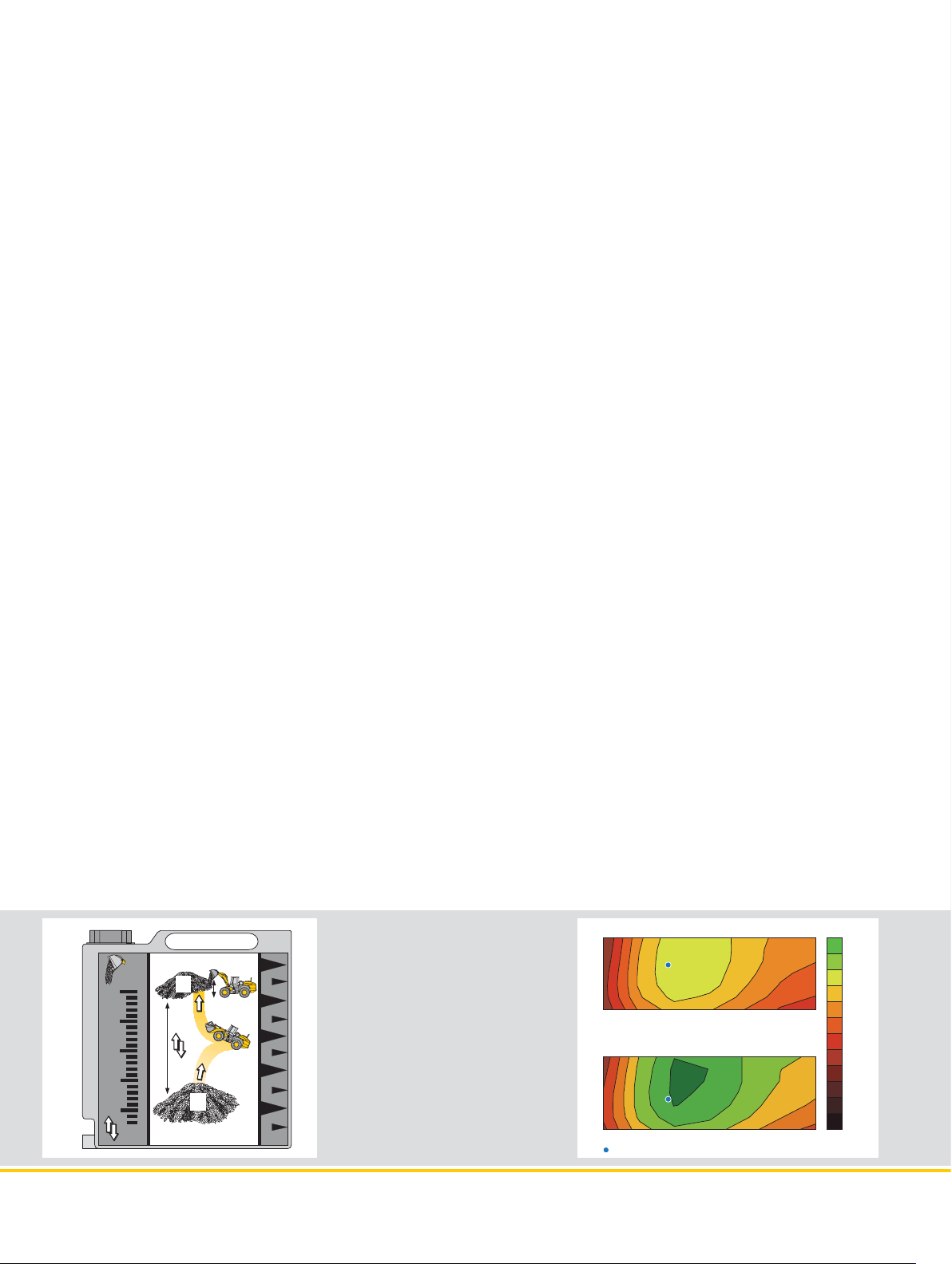
The Liebherr Standard Consumption Test –
easy to reproduce and practical.
The test consits on determining the number of loading cycles that can
be carried out with 1.3 gal of diesel. The material is taken from pile
A and carried over a distance of 65’7” topoint B. The time needed for
each working cycle should be 35seconds. Discharge at point B should
take place from a height of 8’2”. The working cycles continue until the
1.3 gal of diesel in the external measuring tank have been used up. The
loader’s fuel consumption per operating hour is calculated as follows:
35
n=?
B
5
8'2''
4
04.13
30
25
20
15
3
65'7''
T ~ 35 sec.
2
A
1
L0083
Values for the Liebherr Wheel Loaders
working cycles 100 US tons hour hour**
L 524: 2.7 yd3 n = 47 0.82 2.25 1.88
L 528: 3.0 yd
L 538: 3.4 yd
L 542: 3.7 yd
L 550: 4.2 yd
L 556: 4.7 yd
L 566: 5.2 yd
L 580: 6.5 yd
L 586: 7.2 yd
* Equipped with L5 tires and 7.2 yd
** Wheel loader in practical customer applications (with individual
machine configurations).
Number of loading cycles
3
n = 46 0.76 2.30 1.90
3
n = 39 0.79 2.72 2.25
3
n = 38 0.76 2.77 2.30
3
n = 31 0.82 3.41 2.88
3
n = 27 0.84 3.83 3.20
3
n = 22 0.93 4.81 3.99
3
n = 20 0.82 5.28 4.28
3
n = 14 1.05 7.53* 5.42
400
Numbers of Gallons/ Gallons/ Ø Gallons/
=consumption
3
HD bucket
per hour
L 524 – L 542 23
Page 24

Tires
tread code operating weight over tires dimensions Use
lb ft in ft in
L 524/L 528
Bridgestone 17.5R25 VUT L2 – 104 8’ + 0.16” Gravel, Earthworks, Clay (all ground conditions)
Bridgestone 17.5R25 VJT L3 + 201 8’ + 0.71” Bulk material (firm ground conditions)
Bridgestone 17.5R25 VSDL L5 + 1,407 8’ + 2.24” Stone, Scrap, Recycling (firm ground conditions)
Bridgestone 20.5R25 VJT L3 + 1,182 8’ + 2.76” Bulk material (firm ground conditions)
Bridgestone 20.5R25 VSDL L5 + 2,643 8’ + 4.80” Stone, Scrap, Recycling (firm ground conditions)
Bridgestone 550/65R25 VTS L3 + 853 8’1” + 0.47” Gravel (all ground conditions)
Goodyear 17.5R25 RT-3B L3 + 364 8’1” + 0.83” Gravel (all ground conditions)
Goodyear 17.5R25 TL-3A+ L3 + 514 8’1” + 0.91”
Goodyear 17.5R25 RL-4K L4 + 1,224 8’1” + 1.65” Gravel, Industry, Stone (firm ground conditions)
Goodyear 17.5R25 RL-5K L5 + 1,497 8’1” + 1.65” Stone, Scrap, Recycling (firm ground conditions)
Goodyear 20.5R25 RT-3B L3 + 1,168 8’ + 3.07” Gravel (all ground conditions)
Goodyear 20.5R25 TL-3A+ L3 + 1,488 8’1” + 2.87”
Goodyear 20.5R25 GP-4D L4 + 1,867 8’ + 3.23” Gravel, Industry, Wood (firm ground conditions)
Goodyear 20.5R25 RL-4K L4 + 2,440 8’1” + 3.82” Gravel, Industry, Stone (firm ground conditions)
Goodyear 20.5R25 RL-5K L5 + 2,802 8’1” + 4.37” Stone, Scrap, Recycling (firm ground conditions)
Michelin 17.5R25 XTLA L2 – 154 8’1” + 0.71” Gravel, Earthworks, Clay (all ground conditions)
Michelin 17.5R25 XHA L3 0 8’ 0” Sand, Gravel (all ground conditions)
Michelin 17.5R25 XLD D2A L5 + 802 8’1” + 1.46” Stone, Mining spoil (firm ground conditions)
Michelin 17.5R25 X MINE L5 + 1,208 8’2” + 2.32” Stone, Scrap, Recycling (firm ground conditions)
Michelin 20.5R25 XTLA L2 + 877 8’1” + 2.17” Gravel, Earthworks, Clay (all ground conditions)
Michelin 20.5R25 XHA2 L3 + 1,144 8’ + 2.44” Sand, Gravel (all ground conditions)
Michelin 20.5R25 XLD D2A L5 + 2,094 8’ + 3.62” Stone, Mining spoil (firm ground conditions)
Michelin 20.5R25 X MINE L5 + 2,685 8’ + 4.21” Stone, Scrap, Recycling (firm ground conditions)
Michelin 550/65R25 XLD65 L3 + 963 8’1” + 0.71” Gravel (all ground conditions)
L 538/L 542
Bridgestone 20.5R25 VJT L3 + 37 8’2” + 0.31” Bulk material (firm ground conditions)
Bridgestone 20.5R25 VSDL L5 + 1,477 8’ + 2.36” Stone, Scrap, Recycling (firm ground conditions)
Bridgestone 550/65R25 VTS L3 – 97 8’2” – 1.97” Gravel (all ground conditions)
Bridgestone 650/65R25 VTS L3 + 1,312 8’8” + 0.63” Gravel (all ground conditions)
Goodyear 20.5R25 RT-3B L3 + 24 8’2” + 0.63” Gravel (all ground conditions)
Goodyear 20.5R25 TL-3A+ L3 + 344 8’2” + 0.43”
Goodyear 20.5R25 GP-4D L4 + 723 8’1” + 0.79” Gravel, Industry, Wood (firm ground conditions)
Goodyear 20.5R25 RL-4K L4 + 1,296 8’2” + 1.38” Gravel, Industry, Stone (firm ground conditions)
Goodyear 20.5R25 RL-5K L5 + 1,658 8’2” + 1.93” Stone, Scrap, Recycling (firm ground conditions)
Michelin 20.5R25 XTLA L2 – 267 8’3” – 0.28” Gravel, Earthworks, Clay (all ground conditions)
Michelin 20.5R25 XHA2 L3 0 8’2”
Michelin 20.5R25 XLD D2A L5 + 950 8’2” + 1.18” Stone, Mining spoil (firm ground conditions)
Michelin 20.5R25 X MINE L5 + 1,541 8’1” + 1.77” Stone, Scrap, Recycling (firm ground conditions)
Michelin 550/65R25 XLD65 L3 – 181 8’2” – 1.73” Gravel (all ground conditions)
Michelin 650/65R25 XLD65 L3 + 1,054 8’8” – 0.28” Gravel (all ground conditions)
Size and Change of Width Change in vertical
Sand, Gravel, Earthworks, Clay (all ground conditions)
Sand, Gravel, Earthworks, Clay (all ground conditions)
Sand, Gravel, Earthworks, Clay (all ground conditions)
0” Sand, Gravel (all ground conditions)
Before operating the vehicle with tire foam filling or tire protection chains, please discuss this with the Liebherr-Werk Bischofshofen GmbH.
L 524 – L 542 24
Page 25

Equipment
Crash protection, rear
Access to facilitate windscreen cleaning
Exhaust pipe – stainless steel
Automatic central lubrication system
Battery master switch
Diesel particle filter
Electronical theft protection
Electronic tractive force regulation for difficult ground conditions
Automatic travel mode
Speed range selection
Driver identification (in conjunction with electronic theft lock)
Ride control
Parking brake
Particle protection for radiator
Speed limitation, 12.4 mph
Speed limitation V
Large-mesh radiator
Pre-heat system for cold starting
Combined inching-braking system
Fuel tank steel version
Multi-disc limited slip differentials in both axles
LiDAT (Liebherr Data Transfer System) – one year free of charge
Liebherr biodegredable hydraulic oil
Reversible fan drive
Air cleaner system with pre-filter
Emergency steering system
Reversing obstruction detector
Back-up alarm audible
Back-up alarm visual
Tail lights, single version
Rear-view monitoring camera (integrated in dispay unit)
Headlights front, single version (on front-chassis) – halogen
Lockable doors, service flap and engine hood
Widening for fender and rear mudguard (steel design)
Rubber widening for rear mudguards
Air pre-cleaner Top-Air
Hazard warning lights
Toolbox with toolkit
Weighing device for approved or non-approved weighing (integrated in dispay unit)
Towing hitch
max
Operator’s Cab
Storage box
Armrest, adjustable
Exterior mirror, tiltabel
Exterior mirror, heated
Fold-out window (operator’s door)
Operator’s package
Operator’s seat (mechanically sprung)
Operator’s seat – air sprung with seat heating
Operator’s seat – air sprung without seat heating
Fire extinguisher 4 lb
Cup holder
Rear window heater
Horn
Joystick steering
Floor mat
Clothes hook
Air conditioning system (manual)
Automatic air conditioning system
Storage box with cooling function
Steering column, height-adjustable
Steering column, adjustable
Liebherr joystick control – adjustable
Premium Display, Touchscreen (display unit)
Radio set
Provision for radio including loudspeaker
Interior rear-view mirror
Amber beacon
Soundproof ROPS/FOPS cab
Wash/wipe system for windscreen and rear window
Headlights rear, single or double version – halogen/LED
Headlights front, double version – halogen
Headlights front, double version – LED
Headlights front, single version – XENON
Protective ventilation system
Windscreen guard
Sun visor
Sunblind front/rear
Dust filter system
12 V Outlet
First aid kit
Hot water heater with defroster and recirculated-air system
Wide angle mirror
Basic Machine
524
+ + + +
• • • •
+ + + +
+ + + +
• • • •
• • • •
+ + + +
• • • •
• • • •
• • • •
+ + + +
+ + + +
• • • •
+ + + +
+ + + +
• • • •
• • • •
• • • •
• • • •
+ + + +
• • • •
• • • •
+ + + +
• • • •
• • • •
• • • •
+ + + +
• • • •
+ + + +
• • • •
+ + + +
• • • •
• • • •
+ + + +
+ + + +
+ + + +
• • • •
+ + + +
+ + + +
• • • •
524
• • • •
• • • •
• • • •
+ + + +
+ + + +
• • • •
+ + + +
• • • •
+ + + +
• • • •
• • • •
• • • •
• • • •
+ + + +
• • • •
• • • •
• • • •
+ + + +
+ + + +
+ + + +
• • • •
• • • •
+ + + +
+ + + +
• • • •
• • • •
+ + + +
• • • •
• • • •
+ + + +
• • • •
+ + + +
+ + + +
+ + + +
+ + + +
• • • •
+ + + +
+ + + +
• • • •
+ + + +
• • • •
+ + + +
528
528
538
538
542
Quick coupler, opened
Coolant level
Charge air/fuel temperature too high
Steering system / braking system
Engine oil pressure
Reversing obstruction detector
Back-up alarm
Service codes
Overheating of coolant, fuel, hydraulic oil
Audible Warnings for
Display unit
Working hydraulics lockout
Automatic central lubrication system
Battery charge
Operating voltage
Timer for hours of operation
Indicator light / Hazard warning lights / High beam
Brake accumulator pressure
Date/outside temperature
Diesel particle filter
Rev. Counter
Speed range indicator
Driver identification
Travel speed
Travel direction
Parking brake
Gear level
Heater / Air conditioning
Hydraulic oil temperature
Joystick steering
Fuel level
Fuel consumption
Coolant temperature
Reversible fan drive
Engine oil pressure
Emergency steering system
Service codes
System and function settings
Time
Weighing device
Tractive force regulation
542
Warning symbols for
Battery charge
Brake accumulator pressure
Diesel particle filter
Air cleaner blockage
Engine oil pressure
Emergency steering system
Reversing obstruction detector
Engine overspeed
Equipment
Working hydraulics lockout
Automatic hoist kick out – adjustable
Automatic bucket return to dig – adjustable
Fork carrier and lift forks
High-dump bucket
Log Grapple
Hydraulic quick coupler – Z-bar linkage
Hydraulic servo control of working hydraulics
Tilt cylinder protection
Loading buckets with and without teeth, or bolt-on cutting edge
Country-specific versions
Light material bucket
LIKUFIX
Parallel linkage including quick coupler
Parallel linkage including quick coupler – High Lift version
Load holding valves
Float position
Z-bar linkage
3rd hydraulic control circuit
3rd and 4th hydraulic control circuits
• = Standard, + = Option, - = not available
524
528
524
524
524
528
528
528
538
538
538
538
• • • •
• • • •
• • • •
• • • •
• • • •
+ + + +
• • • •
• • • •
• • • •
• • • •
+ + + +
• • • •
+ + + +
• • • •
• • • •
• • • •
+ + + +
• • • •
• • • •
• • • •
+ + + +
• • • •
• • • •
• • • •
• • • •
+ + + +
• • • •
+ + + +
• • • •
+ + + +
• • • •
• • • •
+ + + +
• • • •
• • • •
+ + + +
• • • •
+ + + +
• • • •
• • • •
• • • •
• • • •
• • • •
• • • •
• • • •
+ + + +
• • • •
• • • •
• • • •
• • • •
+ + + +
+ + + +
+ + + +
+ + + +
• • • •
+ + + +
+ + + +
+ + + +
+ + + +
+ + + +
+ + + +
+ + + +
+ + + +
• • • •
• • • •
+ + + +
+ + + +
542
542
542
542
524-542 IIIB 08.13
L 524 – L 542 25
Page 26

The Liebherr Group of Companies
Wide Product Range
The Liebherr Group is one of the largest construction
equipment manufacturers in the world. Liebherr’s
high-value products and services enjoy a high reputation
in many other fields. The wide range includes domestic
appliances, aerospace and transportation systems,
machine tools and maritime cranes.
Exceptional Customer Benefit
Every product line provides a complete range of models
in many different versions. With both their technical
excel lence and acknowledged quality, Liebherr products
offer a maximum of customer benefits in practical
application.
State-of-the-art Technology
To provide consistent, top quality products, Liebherr
attaches great importance to each product area, its
components and core technologies. Important modules
and components are developed and manufactured
in-house, for instance the entire drive and control
techno logyfor construction equipment and mining trucks.
Worldwide and Independent
Hans Liebherr founded the Liebherr family company in
1949. Since that time, the enterprise has steadily grown
to a group of more than 130 companies with over
38,000employees located on all continents. The corporate
headquarters of the Group is Liebherr-International AG
inBulle, Switzerland. The Liebherr family is the sole owner
of the company.
www.liebherr.us
Liebherr Construction Equipment Co.
4100 Chestnut Avenue, Newport News, VA 23607, USA
+1 (757) 245 5251, Fax +1 (757) 928 8701
www.liebherr.us, E-Mail: info.lce@liebherr.com
www.facebook.com/LiebherrConstruction
Printed in Germany by Schirmer RG-BK-RP LBH/PM 11600850-0.5-01.14�enUS
All illustrations and data may differ from standard equipment. Subject to change without notice.
 Loading...