


Liberty Pumps ALM-P1, ALM-2, ALM-2-1, ALM-PK, SJ10A Installation Manual
...
Installation and User Manual |
2138000D |
|
|
|
|
ALM-Series Indoor Alarms
Product Features:
NEMA 1 enclosure - Rated for indoor use only
Automatic alarm and alarm silence reset
360° red alarm indicator beacon
4 ft. (1.2m) power cord
9V Battery back-up with low battery indicator
Pre-installed connector on level sensor for plug-and-play installation
Auxiliary dry contacts for triggering external alarm
Multiple level sensing options available
Internet connectivity available with NightEye® enabled devices
DO NOT THROW AWAY OR LOSE THIS MANUAL
|
Table of Contents |
|
|
|
Models Covered |
|
|
.....................................Safety Information |
1 |
|
|
Standard Models |
|
|
|
|
|
|
|
|
|
General Information .................................. |
2 |
|
|
ALM-P1 |
|
|
|
|
|
|
|
|
|
Installation ................................................. |
3 |
|
|
ALM-2 |
|
|
Operation................................................... |
4 |
|
|
ALM-2-1 |
|
|
Warranty |
5 |
|
|
ALM-PK |
|
|
|
|
|
|
||
|
|
|
|
|
SJ10A |
|
|
|
|
|
|||
|
|
|
|
|
NightEye® Wireless Enabled Models |
|
|
|
|
|
|
ALM-P1-EYE |
|
|
|
|
|
|
ALM-2-EYE |
|
7000 Apple Tree Avenue |
|
|
|
ALM-2-1-EYE |
|
|
Bergen, NY 14416 |
|
|
|
ALM-PK-EYE |
|
|
Phone: (800) 543-2550 |
|
|
|
|
||
|
|
|
|
|
||
Fax: (585) 494-1839 |
|
|
|
SJ10A-EYE |
|
|
|
|
|
|
|
|
|
|
|
|
|
|
|
|
|
© Copyright 2017 Liberty Pumps Inc. |
All rights reserved |
||||

Safety Information
RISK OF ELECTRIC SHOCK
NEVER enter a flooded space without proper Personal Protective Equipment. Always wear dielectric rubber boots and other applicable protective equipment when water is on the floor and you must service an energized pump or alarm system.
NEVER install this alarm system outdoors. The system is rated for indoor use only.
DO NOT enter the water if the water level is higher than that of the protection your PPE offers or if your PPE is not watertight.
DISCONNECT POWER before installing or servicing this product. A qualified service person must install and service this product according to applicable electrical and plumbing codes.
RISK OF FIRE
NEVER use this product with or near flammable liquids.
DO NOT install this product in locations classified as hazardous or in explosive atmospheres as defined by any applicable electrical safety code.
Failure to follow the above precautions could result in serious injury or death. Replace product immediately if sensor or power cable becomes damaged or severed. Keep these instructions in a safe place for future reference. This product must be installed in accordance with National Electric Code, ANSI/NFPA 70 so as to prevent moisture from entering or accumulating within junction boxes, conduit bodies, fittings, float housing, alarm enclosure, or cable.
General Information
Before use, please read the following instructions carefully. Each Liberty Pumps alarm system is tested individually in the factory to ensure proper performance and operation. Closely following these instructions will eliminate potential operating problems, providing years of trouble-free service.
This high water level alarm system is designed for applications such as monitoring sump pump basins, sewage pump basins, and water powered back-up pumps. The alarm system comes standard with a 9V battery back-up to enable continuous water level monitoring, even when the power is out. A built-in battery monitor alerts the user when the 9V battery needs to be replaced.
NightEye® enabled devices come equipped with wireless internet connectivity. These devices can connect to your wireless network, by means of an Android® or iOS® device, and send notifications about your system in real time. This system can provide peace of mind about the status of your sump pump system even when you are not home.
All of the alarms come standard with Liberty Pumps’, patent pending, 360° red alarm beacon powered by super-bright LEDs. In combination with the 86dB (at 10’ (3m)) alarm siren, the alarm is sure to alert occupants of the high-water condition.
Each device is specifically designed for use in an indoor residential wastewater application. The systems come with liquid level sensors that conform to the needs of the intended application. The sensor types are as follows:
Snap-on enclosed float - (ALM-P1, ALM-P1-EYE, SJ10A, SJ10A-EYE) - Sump Pump Applications
Tethered float - ( ALM-2, ALM-2-1, ALM-2-EYE, ALM-2-1-EYE) - Sewage Pump Applications
Water puck - (ALM-PK, ALM-PK-EYE) - Puddle Sensing.
If you need one alarm to monitor multiple locations, Liberty offers a splitter to connect up to 3 sensors (Kit: K001633).
t |
rty |
. |
ts |
r |
3 |
© Copyright 2017 Liberty Pumps Inc. |
All rights reserved |
1 |
|||
Installation
RISK OF ELECTRIC SHOCK
NEVER install this alarm system outdoors. The system is rated for indoor use only.
Enclosure Installation
1)Select an indoor mounting location for the alarm unit. Liberty Pumps recommends a location between 48in (1.2m) and 66in (1.7m) above floor level.
2)Using the supplied template on the rear cover of this manual, mark screw locations on the mounting surface.
3)If the screw locations are NOT directly over a wall stud, or the alarm will be mounted to a masonry wall, the use of the supplied anchors is recommended. A 3/16” (5mm) hole must be drilled before inserting the anchor into the wall.
4)Mount the alarm enclosure to the wall using the supplied anchors and screws (where applicable).
Sensor Installation
Sump Pump Sensor
1)Remove sump pump sensor from packaging.
2)Apply a small amount of glue to the inside of the snap feature of the sensor. NOTE: Over-gluing the sensor will make future removal very difficult.
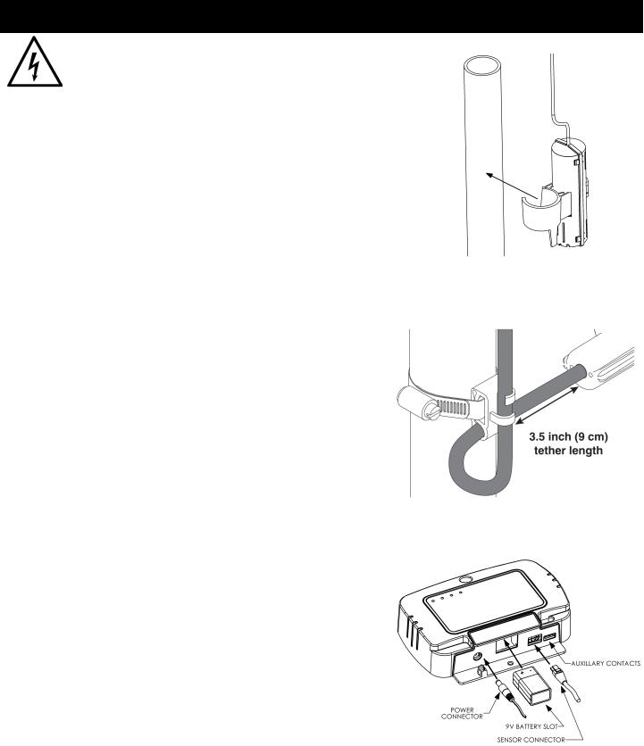
3)Snap sensor over the discharge pipe of your sump pump as shown in Figure 1.
4)Route the sensor cable out of the sump pit and connect it to the bottom of the alarm enclosure. See Figure 3.
Sewage Pump Sensor
1)Place the float switch cord into the clamp as shown in Figure 2.
2)Locate the clamp at the desired activation level and secure the clamp to the pump discharge pipe as shown in Figure 2.
Note: Do not install cord under hose clamp.
3)Tighten the hose clamp using a screwdriver. Over tightening may result in damage to the plastic clamp. Make sure the float cable is not allowed to touch the excess hose clamp band during operation.
Note: All hose clamp components are made of 18-8 stainless steel. See your Liberty Pumps® supplier for replacements.
4)Route the sensor cable out of the sewage pit and connect it to the bottom of the alarm enclosure ensuring it does not interfere with the operation of the primary pump’s float. See Figure 3.
Water Puck Sensor
1)Remove the puck sensor from its packaging.
2)Place sensor in the location susceptible to water intrusion or buildup (example: under hot water heater, near laundry sink, near problematic foundation wall, etc.).
3)Route water puck cable such that it will not pose a tripping hazard.
Figure 1
Sump Pump Sensor Installation
Figure 2
Sewage Pump Sensor Installation
Figure 3
4) |
Plug water puck cable into the ALM sensor connector. |
|
Connection locations on bottom of alarm unit. |
|
5) |
Test water puck for operation by setting it in a small puddle or by |
Note the 9V battery installation—paying |
|
|
|
holding a damp towel on its bottom surface. |
|
attention to polarity, the battery should gently |
|
To install up to 3 sensors, use a Liberty alarm connector splitter |
push into place and latch on the ledge at the |
|
||
bottom of the battery chamber. |
|
|||
(sold separately, Kit: K001633). |
|
|
||
|
|
|
||
|
|
|
|
|
|
ty |
. |
ts |
4 |
|
© Copyright 2017 Liberty Pumps Inc. |
All rights reserved |
2 |
|
Installation (con’t)
Connect Power
1)Connect the supplied power adapter to the alarm unit as shown in Figure 3. Plug the power adapter into the wall receptacle and verify that the green “power” indicator illuminates.
Note: It is recommended that the alarm is connected to a circuit that is separate from the pump circuit. This allows the alarm to continue to operate if the pump circuit fails.
2)Install the 9V battery as shown in Figure 3 (previous page). Paying attention to polarity, the battery should gently push into place and latch on the ledge at the bottom of the battery chamber.
Note: A 9V battery must be installed in the device at all times to ensure proper operation.
NightEye® Configuration
If your device is NightEye® enabled, it is now time to configure the device to connect to your wireless network.
For configuration instructions, please consult the NightEye® quick-start guide that is included with your device. If the quick-start guide has been lost or damaged, electronic copies are available at LibertyPumps.com.
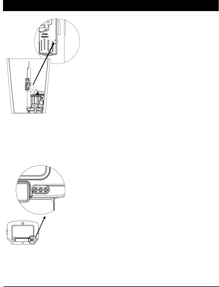
Figure 5
Testing sump pump liquid sensor
1—2—3
Terminal Connections:
1: Normally Open
2: Common
3: No Connection
Figure 6
Auxiliary Contact Connections
NOTE: 24 VDC/VAC, 500 mA MAX
Alarm Testing
Sump Pump Sensor
This switch is a self contained unit. The internal float may not be visible from the outside of the switch housing. The switch should be placed such that the activation point (Figure 5) is slightly higher than the pump activation point.
1)In order to test the proper operation of the float switch, we recommend raising the water level in your sump pit above it’s normal operating level. If raising the water level is not feasible, a cup of water can be used to confirm float operation.
2)When the water level reaches the lowest mark on the side of the float housing, the alarm will activate. (Figure 5)
3)Once alarm begins to sound, it will continue to sound until the water level is lowered. The audible alarm can be silenced using the Silence button on the front of the device. (The alarm will stay silenced for 6 hours after the silence button is pressed)
4)Once testing is complete, lower the water level in the pit back to its normal range.
Sewage Pump Sensor
1)Manually tip the float up.
2)Once alarm begins to sound, it will continue to sound until the float is tipped down. The audible alarm can be silenced using the Silence button on the front of the device. (The alarm will stay silenced for 6 hours after the silence button is pressed.)
3)Lower the float back to its resting position to reset the alarm.
t |
rty |
. |
ts |
r |
5 |
© Copyright 2017 Liberty Pumps Inc. |
All rights reserved |
3 |
|||
Installation (con’t)
Auxiliary Contacts
This device comes equipped with auxiliary contacts. These contacts can be used to integrate the output of this alarm with an existing home monitoring system. See Figure 6 for contact connections diagram.
Contact Rating: Class 2, 24 VDC/VAC (50/60 HZ) 500 mA MAXIMUM
Regular Operation
Now that your alarm unit has been configured and tested, it is ready for operation. The following is a list of regular maintenance tasks:
It is highly recommended that the alarm system be tested every 6 months. Follow the procedure outlined in the Alarm Testing section above.
In the event the 9V battery is low, the alarm will emit a short chirp about twice per minute. The 9V battery should be replaced any time the yellow “low battery” indicator on the alarm unit is lit or every 12 months.
In the event that an alarm condition is detected by the system, the audible and visual alarms will activate. The automatic reset feature of the alarm will turn the audible and visual alarms off once the condition has been corrected.
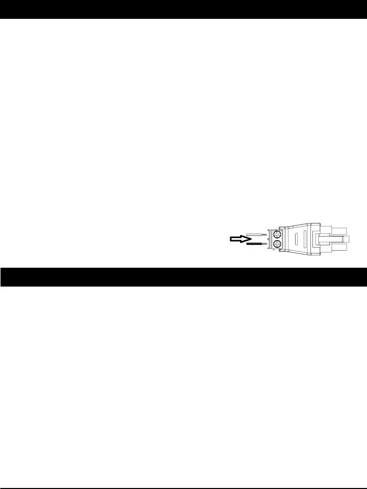
Float Adapter
If your system already has an alarm float installed, and you do not want to replace it with the float included with your Liberty ALM series product, you can use the included terminal block adapter.
1)Turn both screws in the float adapter counter-clockwise, until the conductor receptacles are fully open.
2)Insert the float conductors into the float adapter, one conductor per receptacle. Polarity does not matter.
3)Tighten the screws in the float adapter until they bottom out.
4)Insert the float adapter into the connector on your Liberty ALM series alarm.
3 Year Limited Warranty
Liberty Pumps, Inc. warrants that its products are free from all factory defects in material and workmanship for a period of 3 years from the date of purchase. The date of purchase shall be determined by a dated sales receipt noting the model and serial number of the pump. The dated sales receipt must accompany the returned pump if the date of return is more than 3 years from the "CODE" (date of manufacture) number noted on the pump nameplate.
The manufacturer's sole obligation under this Warranty shall be limited to the repair or replacement of any parts found by the manufacturer to be defective, provided the part or assembly is returned freight prepaid to the manufacturer or its authorized service center, and provided that none of the following warranty-voiding events have taken place.
The manufacturer shall not be liable under this Warranty if the product has not been properly installed; if it has been disassembled, modified, abused or tampered with; if the electrical cord has been cut, damaged or spliced; if the pump discharge has been reduced in size; if the pump has been used in water temperatures above the advertised rating, or in water containing sand, lime, cement, gravel or other abrasives; if the product has been used to pump chemicals or hydrocarbons; if a non-submersible motor has been subjected to excessive moisture; or if the label bearing the serial, model and code number has been removed. Liberty Pumps, Inc. shall not be liable for any loss, damage or expenses resulting from installation or use of its products, or for indirect, incidental, and consequential damages, including costs of removal, reinstallation or transportation.
THE WARRANTIES SET FORTH ABOVE ARE IN LIEU OF ALL OTHER WARANTIES, EXPRESSED OR IMPLIED, INCLUDING WITHOUT LIMITATION, ANY WARRANTY OF MERCHANTABILITY OR FITNESS FOR A PARTICULAR PURPOSE, AND ALL SUCH OTHER WARRANTIES ARE HEREBY DISCLAIMED AND EXCLUDED BY LIBERTY
ty |
. |
ts |
6 |
© Copyright 2017 Liberty Pumps Inc. |
All rights reserved |
4 |
|
 Loading...