Liberty Pumps ALM-P1 User Manual [en, es, fr]

|
Supplemental Installation Manual |
|
7247000C |
|
|
|
|
||
|
|
|
|
|
|
|
|
|
|
 MODEL ALM-P1
Supplemental Installation Instructions for your ALM-P1 Alarm
Product Description
The ALM-P1 is an alarm system that utilizes a water sensor connected to an alarm panel to detect a high water situation in a sump pump application. The sensor clamps on to 1-1/4” or 1-1/2” PVC pipe. When water bridges the probes, the alarm box will activate an alarm light and horn. The horn can be silenced by switching the rocker switch on the side. The alarm light will still function even when the horn is silenced.
Installation of the Water Sensor Probe on discharge pipe
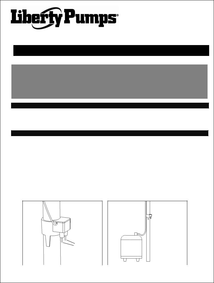
1.The water sensor for the ALM-P1 was designed to be installed directly onto a pump discharge pipe. The clamp will only fit onto 1-1/4” or 1-1/2” pipe. See figures 1 and 2.
2.Determine correct height for the water sensor. The alarm will turn on when the bottom of the probes detect water. The correct height for these probes should be above the turn on point of the pump and well below the top of the sump pit.
3.Connect wires from water sensor to the alarm panel. Red wire must be connected to the “left” terminal, labeled R/W. The black wire must be connected to the “right” terminal, labeled B. Wire up to the panel can be secured to the pipe with the included zip tie.
4.Test the pump and the turn on level of the alarm. When satisfied with the probe position, mark the level on the discharge pipe. For added security, slide the probe clamp away from intended position and apply a small amount of PVC glue to the discharge pipe. Return the alarm probe to desired position. The PVC glue will bond the pipe and clamp to prevent accidental movement.
5.To test the water sensor, immerse both probes in water or place a wet rag or sponge across the probes. The alarm panel should activate. Completely wipe and dry the probes before putting the unit back into service.
Probe level
|
|
Probe level |
|
|
||
|
|
|
|
|
1-1/4” or 1-1/2” |
|
|
|
1-1/4” or 1-1/2” |
discharge |
|
||
|
|
discharge |
|
|
||
|
|
|
|
|
Figure 2 |
|
Figure 1 |
|
|||||
|
©Copyright 2012 Liberty Pumps Inc. |
All rights reserved |
1 |
|||

 Installation of the Water Sensor Probe with SumpJet® Model SJ10
The ALM-P1 was specifically designed for use with the SJ10 water-powered backup sump pump. With the water sensor probe in the correct position, the alarm will activate before the pump activates, to let you know when the SJ10 backup is in use. During a power outage, the rocker switch can be deployed to the “silence” position to eliminate the alarm from going off multiple times. The switch should be returned to the “on” position after the power outage has ended, for normal operation.
1.The correct position for the water sensor clamp is already determined on the SJ10, to trigger just before the pump activates. The clamp should be placed on the intake pipe of the SJ10 pump, with the bottom of the clamp touching the top of the pump’s foot valve. If the clamp is not positioned directly against the foot valve, the alarm may not function properly. The clamp should be rotated so that the probes face away from the SJ10 float. See figure 3.
2.Connect wires from water sensor to the alarm panel. Red wire must be connected to the “left” terminal, labeled R/W. The black wire must be connected to the “right” terminal, labeled B. Wire up to the panel can be secured to the pipe with the included zip tie.
3.For added security, slide the probe clamp away from intended position and apply a small amount of PVC glue to the discharge pipe. Return the alarm probe to desired position. The PVC glue will bond the pipe and clamp to prevent accidental movement.
4.To test the water sensor, immerse both probes in water or place a wet rag or sponge across the probes. The alarm panel should activate. Completely wipe and dry the probes before putting the unit back into service.
SJ10 Float
ALM-P1
Important .
For proper installation height, probe clamp must be touching the top of the foot valve.
SJ10 Foot
Valve
Figure 3
©Copyright 2012 Liberty Pumps Inc. All rights reserved |
2 |


 Installation of the Alarm Panel
The ALM-P1 alarm panel is powered by 120 VAC coming from standard wall outlets which is transformed to 9VDC. A 9 Volt battery provides battery back-up power so that the alarm will function in the event of a power failure.
When the water bridges the two probes, the alarm horn and light will turn “on” and the alarm panel’s auxiliary contacts will be activated. The rocker switch on the side of the alarm panel can be used to silence the horn.
Test product weekly. Make sure the green “power on” light is “on”. Press the “Test” switch”; the red alarm light and horn should turn “on”. If the battery back-up system is utilized, unplug the wall mount power supply (the green light will be off). Now press the “ Test” switch; the red alarm light and buzzer will “on”. If the buzzer sounds less loudly than when tested with the normal power supply, then the battery should be replaced.
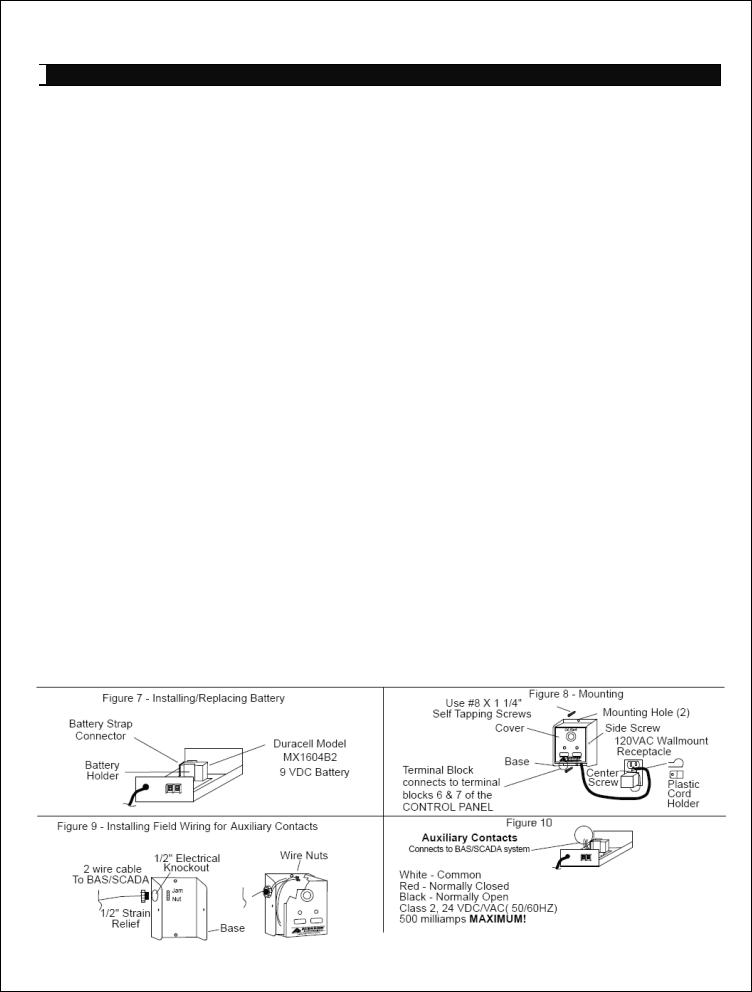
1.To install/replace the battery for the backup power feature, remove the two side screws and install 9 VDC battery. After installing battery, press the test button to activate the alarm to make sure the battery works properly. Reinstall side screws. See figure 4.
2.Determine mounting location for the Alarm Panel. Make sure power outlet is within 6 feet of the alarm. Make sure the outlet is on a separate circuit breaker from any other device and not on a switched receptacle to maintain power integrity. Mount the alarm using two #8 x 1-1/4” self tapping screws (not included). Use #8 plastic anchor if mounting to sheet rock. See figure 5.
3.If auxiliary contacts used, continue; otherwise go to step 4. Remove cover from base and remove ½” electrical knockout from base. Use 16-2 AWG stranded wire – make sure there is at least 6’” of wire inside of enclosure. Install a ½” strain relief with jam nut. Connect wires for required application using wire nuts. Caution! – When installing wires, route all wires away from sharp objects & internal components. See figures 6 & 7.
4.There are two terminals on the bottom of the alarm panel. The red wire from the water sensor probe must be connected to the “left” terminal, labeled R/W. The black wire from the water sensor probe must be connected to the “right” terminal, labeled B.
5.Plug the power supply into a 120 VAC standard wall outlet. For UL applications, remove center screw on receptacle and place cord from wall mount transformer inside the plastic cord holder. Secure plastic cord holder to the receptacle by reinstalling screw to the center hole of receptacle. See figure 5. For Canadian applications DO NOT INSTALL plastic cord holder! The green “Normal” light should come on.
6.Test the system by pressing the “Test” button. The horn and the red warning light will be “on”. The green “Normal” light will be “off’. While holding the “Test” button, switch the side rocker switch to the “Silence” position. The horn will silence, but the alarm light will stay “on”. Let go of the “Test” button and the alarm light will turn “off” and the green “Normal” light will turn “on”. Switch the rocker switch back into the “normal” position and the system is now in operating condition.
|
Figure 4 |
|
|
|
Figure 5 |
|
|
|
|
|
|
|
|
|
|
|
|
|
|
|
|
|
|
|
|
|
|
|
|
|
|
|
|
|
|
|
|
|
|
|
|
|
|
|
|
|
|
|
|
|
|
|
|
|
|
Figure 6 |
Figure 7 |
|
©Copyright 2012 Liberty Pumps Inc. |
All rights reserved |
3 |

Liberty Pumps, 3 Year Limited Warranty
Liberty Pumps, Inc. warrants that pumps of its manufacture are free from all factory defects in material and workmanship for a period of 3 years from the date of purchase. The date of purchase shall be determined by a dated sales receipt noting the model and serial number of the pump. The dated sales receipt must accompany the returned pump if the date or return is more than 3 years from the “CODE” (date of manufacture) number noted on the pump nameplate.
The manufacturer’s obligation under this Warranty shall be limited to the repair or replacement of any parts found by the manufacturer to be defective, provided the part or assembly is returned freight prepaid to the manufacturer or its authorized service center, and provided that none of the following warranty-voiding characteristics are evident:
The manufacturer shall not be liable under this Warranty if the product has not been properly installed; if it has been disassembled, modified, abused or tampered with; if the electrical cord has been cut, damaged, or spliced; if the pump discharge has been reduced in size; if the pump has been used in water containing sand, lime, cement, gravel or other abrasives; if the product has been used to pump chemicals or hydrocarbons; if a non-submersible motor has been subjected to excessive moisture; or if the label bearing the serial, model, and code number has been removed.
Liberty Pumps, Inc. shall not be liable for any loss, damage or expenses resulting from installation or use of its products, or for consequential damages, including costs of removal, reinstallation or transportation.
There is no other express warranty. All implied warranties, including those of merchantability and fitness for a particular purpose, are limited to three years from the date or purchase.
This warranty contains the exclusive remedy of the purchaser, and, where permitted, liability for consequential or incidental damages under any and all warranties are excluded.
7000 Apple Tree Avenue
Bergen, NY 14416 Phone 800-543-2550 www.libertypumps.com
©Copyright 2012 Liberty Pumps Inc. All rights reserved |
4 |
 Loading...