


Installation Manual |
7035000J |
|
|
|
|
Heavy Duty Submersible Effluent/Dewatering Pumps
*Do not throw away or lose this manual.
Models
250-Series |
1/3 HP |
280-Series |
1/2 HP |
290-Series |
3/4 HP |
FL30-Series |
1/3 HP |
FL50-Series |
1/2 HP |
FL60-Series |
6/10 HP |
FL100-Series |
1 HP |
FL150-Series |
1-1/2 HP |
FL200-Series |
2 HP |
Contents |
|
General Information
Dewatering/Sump Applications
Effluent Applications
Electrical Service and Operation |
|
IMPORTANT: |
|
||||
|
Prior to installation, record Model, Serial Number, and |
|
|||||
|
|
|
|
|
|
||
|
Maintenance and Troubleshooting |
|
Code Number from pump nameplate for future reference. |
|
|||
|
Warranty |
|
|
MODEL |
________________________ |
|
|
|
|
SERIAL |
______________________ |
|
|||
|
|
|
|
|
|
||
|
|
|
|
|
CODE |
______________________ |
|
|
|
|
|
|
INSTALLATION |
|
|
|
7000 Apple Tree Avenue |
|
|
|
|||
|
|
|
DATE |
_______________________ |
|
||
|
Bergen, NY 14416 |
|
|
|
|||
|
|
|
|
|
|
||
|
Phone: (800) 543-2550 |
|
|
|
|
|
|
|
Fax: (585) 494-1839 |
|
|
|
|
|
|
|
www.libertypumps.com |
* FL60 Series is cCSA only |
|
|
|
||
|
|
|
|
|
|
|
|
|
|
|
|
|
|
|
|
©Copyright 2012 Liberty Pumps Inc. All rights reserved

1. General Information
Before Installation, read the following instructions carefully. Each Liberty pump is individually factory tested to assure proper performance. By closely following these instructions, potential operating problems should be eliminated, providing years of trouble-free service.
Risk of electric shock. Always disconnect the pump from the power source before handling or making adjustments.
The electrical connections and wiring for a pump installation should only be made by qualified personnel.
This pump is supplied with a grounding conductor and grounding-type attachment plug. To reduce the risk of electric shock, be certain that it is connected only to a properly grounded receptacle.
Always wear rubber boots when water is on the floor and you must unplug the pump.
DO NOT bypass grounding wires or remove ground prong from attachment plugs.
DO NOT use an extension cord.
Always use a replacement power cord assembly of the same length and type as originally installed on the Liberty product. Using a cord of improper gauge or length may lead to exceeding the electrical rating of the cord and could result in death, injury, fire or other significant failure.
This pump requires a separate, properly fused and grounded branch circuit. Make sure the power source is properly sized for the voltage and amperage requirements of the pump, as noted on the nameplate.
The electrical outlet shall be within the length limitations of the pump power cord, and at least 4 feet above floor level to minimize possible hazards from flood conditions.
The installation must be in accordance with the National Electric Code, Uniform Plumbing Code, International Plumbing Code, as well as all applicable local codes and ordinances.
Sump and sewage pumps often handle materials which could cause illness or disease. Wear adequate protective clothing when working on a used pump or piping.
Never enter a pump basin after it has been used. Sewage and effluent can emit several gases which are poisonous.
Keep clear of suction and discharge openings. To prevent injury, never insert fingers into pump while it is plugged in.
DO NOT use this product for flammable or corrosive liquid.
DO NOT use this product in applications where human contact with the pumped fluid is common (such as swimming pools, fountains, etc.)
NEVER dispose of materials such as paint thinner or other chemicals down drains, as they can chemically attack and damage pump components, potentially causing product malfunction or failure.
DO NOT use pumps in water over 140 F (60 C).
DO NOT use pumps in mud, sand, cement, oil or chemicals.
DO NOT modify the pump in any way.
DO NOT lift or carry pump by power cord.
DO NOT remove any tags from pump or cords.
If pump is installed during construction before power is available, it must be protected from the environment to prevent water from entering through the cord plug end, etc.
Tools Required:
-Pipe wrench
-Regular screw driver
-Hacksaw (For replacement or removal of existing rigid piping.)
Removal of old pump
Disconnect old pump from power source before handling.
Separate the discharge pipe at either the check valve or at the union. If neither a check valve nor a union is part of the existing discharge pipe, cut the pipe with a hacksaw and remove the pump (A union or check valve will need to be installed at this cut).
©Copyright 2012 Liberty Pumps Inc. All rights reserved
2

 MODEL SPECIFICATIONS
|
Model |
|
|
HP |
|
|
Volts |
|
|
Full Load Amps |
|
|
Solids Handling |
|
|
Automatic |
|
|
Shut-off Head |
|
|
Factory Switch Setting |
|
|
|||||
|
|
|
|
|
|
|
|
|
|
|
|
|
|
|
|||||||||||||||
|
|
|
|
|
|
|
|
|
|
|
Or Manual* |
|
|
|
|
|
Turn-on |
|
|
|
Turn-off |
|
|
||||||
|
|
|
|
|
|
|
|
|
|
|
|
|
|
|
|
|
|
|
|
|
|
|
|
||||||
|
|
|
|
|
|
|
|
|
|
|
|
|
|
|
|
|
|
|
|||||||||||
250* |
|
1/3 |
|
115 |
|
5.2 |
|
|
1/2” |
|
Manual* |
|
22 ft. |
|
* |
|
|
|
|
|
|
||||||||
251 |
|
1/3 |
|
115 |
|
5.2 |
|
|
1/2” |
|
Automatic |
|
22 ft. |
|
|
11” |
|
|
|
4-1/2” |
|
||||||||
253 |
|
1/3 |
|
115 |
|
5.2 |
|
|
1/2” |
|
Automatic |
|
22 ft. |
|
|
11” |
|
|
|
4-1/2” |
|
||||||||
257 |
|
1/3 |
|
115 |
|
5.2 |
|
|
1/2” |
|
Automatic |
|
22 ft. |
|
|
7” |
|
|
|
3-1/2” |
|
||||||||
|
250HV* |
1/3 |
|
230 |
|
2.6 |
|
|
1/2” |
|
Manual* |
|
22 ft. |
|
* |
|
|
|
|
|
|
||||||||
|
251HV |
1/3 |
|
230 |
|
2.6 |
|
|
1/2” |
|
Automatic |
|
22 ft. |
|
|
11” |
|
|
|
4-1/2” |
|
||||||||
|
257HV |
1/3 |
|
230 |
|
2.6 |
|
|
1/2” |
|
Automatic |
|
22 ft. |
|
|
7” |
|
|
|
3-1/2” |
|
||||||||
|
|
|
|
|
|
|
|
|
|
|
|
|
|
|
|
|
|
|
|
|
|
|
|
|
|
|
|
|
|
280* |
|
1/2 |
|
115 |
|
8.5 |
|
|
3/4” |
|
Manual* |
|
37 ft. |
|
* |
|
|
|
|
|
|
||||||||
281 |
|
1/2 |
|
115 |
|
8.5 |
|
|
3/4” |
|
Automatic |
|
37 ft. |
|
|
13” |
|
|
|
7” |
|
||||||||
283 |
|
1/2 |
|
115 |
|
8.5 |
|
|
3/4” |
|
Automatic |
|
37 ft. |
|
|
13” |
|
|
|
7” |
|
||||||||
287 |
|
1/2 |
|
115 |
|
8.5 |
|
|
3/4” |
|
Automatic |
|
37 ft. |
|
|
9-1/2” |
|
|
|
4” |
|
||||||||
|
280HV* |
1/2 |
|
208-230 |
|
4.6 |
|
|
3/4” |
|
Manual* |
|
37 ft. |
|
* |
|
|
|
|
|
|
||||||||
|
281HV |
1/2 |
|
208-230 |
|
4.6 |
|
|
3/4” |
|
Automatic |
|
37 ft. |
|
|
13” |
|
|
|
7” |
|
||||||||
|
283HV |
1/2 |
|
208-230 |
|
4.6 |
|
|
3/4” |
|
Automatic |
|
37 ft. |
|
|
13” |
|
|
|
7” |
|
||||||||
|
287HV |
1/2 |
|
208-230 |
|
4.6 |
|
|
3/4” |
|
Automatic |
|
37 ft. |
|
|
9-1/2” |
|
|
|
4” |
|
||||||||
|
|
|
|
|
|
|
|
|
|
|
|
|
|
|
|
|
|
|
|
|
|
|
|
|
|
|
|
|
|
290* |
|
3/4 |
|
115 |
|
10.4 |
|
|
3/4” |
|
Manual* |
|
48 ft. |
|
* |
|
|
|
|
|
|
||||||||
291 |
|
3/4 |
|
115 |
|
10.4 |
|
|
3/4” |
|
Automatic |
|
48 ft. |
|
|
13” |
|
|
|
7” |
|
||||||||
293 |
|
3/4 |
|
115 |
|
10.4 |
|
|
3/4” |
|
Automatic |
|
48 ft. |
|
|
13” |
|
|
|
7” |
|
||||||||
297 |
|
3/4 |
|
115 |
|
10.4 |
|
|
3/4” |
|
Automatic |
|
48 ft. |
|
|
9-1/2” |
|
|
|
4” |
|
||||||||
|
290HV* |
3/4 |
|
208-230 |
|
5.3 |
|
|
3/4” |
|
Manual* |
|
48 ft. |
|
* |
|
|
|
|
|
|
||||||||
|
291HV |
3/4 |
|
208-230 |
|
5.3 |
|
|
3/4” |
|
Automatic |
|
48 ft. |
|
|
13” |
|
|
|
7” |
|
||||||||
|
293HV |
3/4 |
|
208-230 |
|
5.3 |
|
|
3/4” |
|
Automatic |
|
48 ft. |
|
|
13” |
|
|
|
7” |
|
||||||||
|
297HV |
3/4 |
|
208-230 |
|
5.3 |
|
|
3/4” |
|
Automatic |
|
48 ft. |
|
|
9-1/2” |
|
|
|
4” |
|
||||||||
|
|
|
|
|
|
|
|
|
|
|
|
|
|
|
|
|
|
|
|
|
|
|
|
|
|
|
|
|
|
|
FL31M* |
1/3 |
|
115 |
|
13 |
|
|
3/4” |
|
Manual* |
|
19 ft. |
|
* |
|
|
|
|
|
|
||||||||
|
FL31A |
1/3 |
|
115 |
|
13 |
|
|
3/4” |
|
Automatic |
|
19 ft. |
|
|
12” |
|
|
|
5” |
|
||||||||
|
FL32M* |
1/3 |
|
208-230 |
|
7 |
|
|
3/4” |
|
Manual* |
|
19 ft. |
|
* |
|
|
|
|
|
|
||||||||
|
FL32A |
1/3 |
|
208-230 |
|
7 |
|
|
3/4” |
|
Automatic |
|
19 ft. |
|
|
12” |
|
|
|
5” |
|
||||||||
|
|
|
|
|
|
|
|
|
|
|
|
|
|
|
|
|
|
|
|
|
|
||||||||
|
|
|
|
|
|
|
|
|
|
|
|
|
|
|
|
|
|
|
|
|
|
|
|
|
|
|
|
|
|
|
FL51M* |
1/2 |
|
115 |
|
12 |
|
|
1/2” |
|
Manual* |
|
48 ft. |
|
* |
|
|
|
|
|
|
||||||||
|
FL51A |
1/2 |
|
115 |
|
12 |
|
|
1/2” |
|
Automatic |
|
48 ft. |
|
|
12” |
|
|
|
5” |
|
||||||||
|
FL52M* |
1/2 |
|
208-230 |
|
7 |
|
|
1/2” |
|
Manual* |
|
48 ft. |
|
* |
|
|
|
|
|
|
||||||||
|
FL52A |
1/2 |
|
208-230 |
|
7 |
|
|
1/2” |
|
Automatic |
|
48 ft. |
|
|
12” |
|
|
|
5” |
|
||||||||
|
|
|
|
|
|
|
|
|
|
|
|
|
|
|
|
|
|
|
|
|
|
||||||||
|
|
|
|
|
|
|
|
|
|
|
|
|
|
|
|
|
|
|
|
|
|
|
|
|
|
|
|
|
|
|
FL61M* |
6/10 |
|
115 |
|
13 |
|
|
1/2” |
|
Manual* |
|
63 ft. |
|
* |
|
|
|
|
|
|
||||||||
|
FL61A |
6/10 |
|
115 |
|
13 |
|
|
1/2” |
|
Automatic |
|
63 ft. |
|
|
12” |
|
|
|
5” |
|
||||||||
|
FL62M* |
6/10 |
|
208-230 |
|
7 |
|
|
1/2” |
|
Manual* |
|
63 ft. |
|
* |
|
|
|
|
|
|
||||||||
|
FL62A |
6/10 |
|
208-230 |
|
7 |
|
|
1/2” |
|
Automatic |
|
63 ft. |
|
|
12” |
|
|
|
5” |
|
||||||||
|
|
|
|
|
|
|
|
|
|
|
|
|
|
|
|
|
|
|
|
|
|||||||||
|
|
|
|
|
|
|
|
|
|
|
|
|
|
|
|
|
|
|
|
|
|
|
|
|
|
|
|
|
|
|
FL102M* |
1 |
|
208-230 |
|
12 |
|
|
3/4” |
|
Manual* |
|
90 ft. |
* |
|
* |
|
|
|||||||||||
|
FL102A |
1 |
|
208-230 |
|
12 |
|
|
3/4” |
|
Automatic |
|
90 ft. |
|
|
15” |
|
|
|
8” |
|
||||||||
|
FL103M* |
1 |
|
|
208-230 3 PH |
9 |
|
|
3/4” |
|
Manual* |
|
90 ft. |
* |
|
* |
|
|
|||||||||||
|
FL104M* |
1 |
|
|
440-480 3 PH |
4.5 |
|
|
3/4” |
|
Manual* |
|
90 ft. |
* |
|
* |
|
|
|||||||||||
|
FL105M* |
1 |
|
|
575 3 PH |
3.3 |
|
|
3/4” |
|
Manual* |
|
90 ft. |
* |
|
* |
|
|
|||||||||||
|
|
|
|
|
|
|
|
|
|
|
|
|
|
|
|
|
|
|
|
|
|
|
|
|
|
|
|
|
|
|
FL152M* |
1-1/2 |
|
208-230 |
|
15 |
|
|
3/4” |
|
Manual* |
|
110 ft. |
* |
|
* |
|
|
|||||||||||
|
FL152A |
1-1/2 |
|
208-230 |
|
15 |
|
|
3/4” |
|
Automatic |
|
110 ft. |
|
|
15” |
|
|
|
8” |
|
||||||||
|
FL153M* |
1-1/2 |
|
|
208-230 3 PH |
10.6 |
|
|
3/4” |
|
Manual* |
|
110 ft. |
* |
|
* |
|
|
|||||||||||
|
FL154M* |
1-1/2 |
|
|
440-480 3 PH |
5.3 |
|
|
3/4” |
|
Manual* |
|
110 ft. |
* |
|
* |
|
|
|||||||||||
|
FL155M* |
1-1/2 |
|
|
575 3 PH |
4.9 |
|
|
3/4” |
|
Manual* |
|
110 ft. |
* |
|
* |
|
|
|||||||||||
|
|
|
|
|
|
|
|
|
|
|
|
|
|
|
|
|
|
|
|||||||||||
|
|
|
|
|
|
|
|
|
|
|
|
|
|
|
|
|
|
|
|
|
|
|
|
|
|
|
|
|
|
|
FL202M* |
2 |
|
208-230 |
|
15 |
|
|
3/4” |
|
Manual* |
|
130 ft. |
* |
|
|
* |
|
|
||||||||||
|
FL202A |
2 |
|
208-230 |
|
15 |
|
|
3/4” |
|
Automatic |
|
130 ft. |
|
|
15” |
|
|
|
8” |
|
||||||||
|
FL203M* |
2 |
|
|
208-230 3 PH |
10.6 |
|
|
3/4” |
|
Manual* |
|
130 ft. |
* |
|
* |
|
|
|||||||||||
|
FL204M* |
2 |
|
|
440-480 3 PH |
5.3 |
|
|
3/4” |
|
Manual* |
|
130 ft. |
* |
|
* |
|
|
|||||||||||
|
FL205M* |
2 |
|
|
575 3 PH |
4.9 |
|
|
3/4” |
|
Manual* |
|
130 ft. |
* |
|
* |
|
|
|||||||||||
|
|
|
|
|
|
|
|
|
|
|
|
|
|
|
|
|
|
|
|
|
|
|
|
|
|
|
|
|
|
Note: Manual models (“M” suffix) and 3 phase models, as designated above, require a separate approved pump control device or panel for automatic operation. Operation of these models will be according to the control selected. Make sure the electrical specifications of the control selected properly match the electrical specifications of the pump. 3 phase models require overload elements selected or adjusted in accordance with the control or panel instructions.
©Copyright 2012 Liberty Pumps Inc. All rights reserved
3

2.Dewatering / Sump Applications
1.For ordinary ground water pumping applications, a sump pit of not less than 14" in diameter is recommended. Vertical float (VMF) models (257, 287 and 297) may be used in a minimum 10" diameter sump; however, a larger diameter pit is preferred as it allows for a longer pump cycle and reduced switch cycling. The minimum depth of the pit should be 18".
2.If the pit is not already enclosed on the bottom, provide a hard level bottom of bricks or concrete. DO NOT place the pump directly on earth, gravel or debris since this can cause excessive wear of the impeller and possible jamming. “The Brick” (sold by Liberty Pumps as part # 4445000) is a pre-molded stable platform designed to fit your submersible pump. It raises the pump 2.5” off the bottom of the pit, reducing the potential for jamming from rocks and debris. Contact your local distributor to order. Remove all debris from the bottom of the sump pit before installation of the pump. A sump pit cover is suggested for safety and to prevent foreign objects from entering the pit.
3.Set the pump in the pit making sure the switch has adequate clearance and will not hang-up on the pit wall. The float must be free to move throughout its travel and not contacting the pump body, piping, or other objects. A 1- 1/2" threaded discharge is provided for connection of the discharge pipe. Do not reduce the discharge size to below 1-1/2”. Schedule 40 PVC pipe is recommended; however, flexible discharge hose kits may be used for temporary installations.
4.Connect the pipe or the discharge hose to the discharge of the pump. HAND TIGHTEN ONLY. Over tightening may cause the pump housing to crack. Install a union or other means of separating the discharge line just above the floor to facilitate removal of the pump if necessary. A check valve is recommended just above or in place of the union to prevent the backflow of water after each pump cycle. (All Liberty effluent/dewatering pumps come equipped with an air bleed hole in the base of the pump to help prevent airlock. A small spray of water from this hole is normal while pump is running.)
5.Connect additional piping as needed to direct the discharge to the desired location. Discharge should be kept as short as possible with a minimum number of turns. Check all connections for security.
6.Install a union or other means of separating the discharge pipe just above the floor to facilitate removal of the pump if necessary. A check valve is recommended just above, or in place of, the union to prevent the backflow of water after each pump cycle.
7.If a check valve is used, a 1/8” anti-airlock hole should be drilled in the discharge pipe just above the pump’s discharge outlet to prevent pump “airlock” (see Fig. 1)
Drill 1/8” antiairlock hole. Water spray is normal.
Fig. 1 – Anti-airlock hole position
8. For added protection, consider the addition of a back-up pump such as Liberty’s SJ10 SumpJet, as well as an alarm such as Liberty’s ALM-2 in applications where loss of pump function could result in property damage. If an alarm is used, it must be connected to a separate electrical circuit.
©Copyright 2012 Liberty Pumps Inc. All rights reserved
4

3. Effluent Applications
Vertical Magnetic Float (VMF) models (257, 287 and 297) are not recommended for effluent applications due to their short On/Off cycle. Wide angle float models are better suited for effluent applications and are easily adjustable for different On/Off levels.
The basin required for effluent applications must be sealed and vented to meet health and plumbing code requirements. Proper basin size and basin materials for effluent applications vary depending on the type of effluent system and local codes. Check with your local codes official prior to purchasing and installing the basin. Follow the manufacturer's recommended guidelines for installation of your specific basin. A minimum diameter of 18" and depth of 24" is required for proper pump operation, but larger basins are preferred for longer pump cycles and increased switch life. Installation should be at a sufficient depth to ensure that all plumbing is below the frost line. If this is not feasible, delete the check valve and size the basin and/or adjust the pump differential to
accommodate the additional backflow.
These pumps are not to be installed in locations classified as hazardous in accordance with the National Electric Code, ANSI/NFPA 70, or where prohibited by local codes.
A.Simplex (One Pump) Systems (see Fig. 2): Set the pump in place making sure the float has adequate clearance to the side wall of the basin. The float must be free to move throughout its travel and not contacting the pump body, piping, or other objects. If an optional control device or float is used, follow the directions for mounting that accompany the optional control. Connect the discharge pipe to the pump's threaded discharge. IMPORTANT: DO NOT REDUCE THE DISCHARGE PIPE SIZE BELOW THAT WHICH IS PROVIDED ON THE PUMP. Contact Liberty Pumps or other qualified person if you
have questions regarding proper pipe sizes and flow rates. Mount the basin cover making sure it is properly sealed.
Installation of Discharge: After the pump has been mounted, install the discharge line. A union should be installed to facilitate pump removal if necessary. A free-flow swing check valve is recommended after the union to prevent the backflow of liquid after each pumping cycle. A gate valve should follow the check valve to allow periodic cleaning of the check valve or removal of the pump. The remainder of the discharge line should be as short as possible with a minimum number of turns, to minimize friction head loss. Contact Liberty Pumps or other qualified person if you have questions regarding proper pipe sizes and flow rates.
(All Liberty effluent/dewatering pumps come equipped with an air bleed hole in the base of the pump to help prevent airlock. A small spray of water from this hole is normal while pump is running.)
B.Duplex (Two Pump) Systems (see Fig. 3): Set both pumps in place in the bottom of the basin. The duplex control used
will include 3 or 4 floats that will either be tethered to one of the discharge pipes or to an independent rod or bracket.
Fig. 2 – Typical Installation Simplex System
This is a recommended installation only. Variations may apply.
Fig. 3 – Typical Installation Duplex System
This is a recommended installation only. Variations may apply.
©Copyright 2012 Liberty Pumps Inc. All rights reserved
5

Follow the instructions provided with your duplex control device. Each float must be free to move throughout its travel and not contacting the pump body, piping, or other objects. Connect an individual discharge pipe to each pump. IMPORTANT: DO NOT REDUCE THE DISCHARGE PIPE SIZE BELOW THAT WHICH IS PROVIDED ON THE PUMP. Contact Liberty Pumps or other qualified person if you have any questions regarding proper pipe sizes and flow rates. To eliminate fluid recycling in duplex installations, it is necessary to have a check valve on each discharge line prior to tying the two discharges into one common line. Depending on the height of your basin, the check valves may either be installed inside the basin or outside the basin. Mount the basin cover(s) making sure they are properly sealed.
Installation of Remaining Discharge: Unions or flexible connectors should be installed to facilitate removal of the pump if necessary. Free-flow swing check valves should be installed on each discharge after the union and prior to the gate valve to prevent the back flow of liquid or gas. A check valve on each discharge line, prior to tying into one common line, is necessary to prevent the recycling of fluid from one pump to the other. A gate valve is recommended after the check valve to allow for periodic cleaning of the check valve or removal of the pump. The remainder of the discharge line should be as short as possible with a minimum number of turns to minimize friction head loss. Contact Liberty Pumps or other qualified person if there are questions regarding proper pipe size or flow rates. (All Liberty effluent/dewatering pumps come equipped with an air bleed hole in the base of the pump to help prevent airlock. A small spray of water from this hole is normal while pump is running.)
4. Electrical Service and Operation
Risk of electric shock. Always disconnect the pump from the power source before handling or making adjustments.
The electrical connections and wiring for a pump installation should only be made by qualified personnel.
This pump is supplied with a grounding conductor or a grounding type attachment plug. To reduce the risk of electric shock, be certain that the grounding conductor is connected only to a properly grounded control panel or, if equipped with a grounding type plug that it is connected to a properly grounded, grounding type receptacle.
DO NOT bypass grounding wires or remove ground prongs from attachment plugs.
DO NOT use an extension cord.
This pump requires separate, properly fused and grounded branch circuit. Make sure the power source is properly sized for the voltage and amperage requirements of the motor, as noted on the pump nameplate.
The electrical outlet or panel shall be within the length limitations of the pump power cord, and at least 4 feet above floor level to minimize possible hazards from flood conditions.
The installation must be in accordance with the National Electric Code and all applicable local codes and ordinances.
When the risk of property damage from high water levels exists, an independent high water alarm or back up pump system should be installed.
All FL-Series automatic models (designated with the letter "A") and Models 253, 283 and 293, come factory-equipped with a float switch mounted to the pump. These models come with two cords - one to the float switch and the other to the pump motor. The switch cord has a series (piggyback) plug enabling the pump (motor) cord to be plugged into the back of it. The purpose of this design is to allow manual operation of the pump.
For manual operation, or in the event of switch failure, the pump cord can be separated and plugged into the electrical outlet, directly bypassing the switch (see Fig. 4).Fig. 1 Piggyback plug installation.
|
|
TEMPORARY |
DON’T! |
NORMAL |
MANUAL |
OPERATION |
Fig. 4 – Temporary manual operation
©Copyright 2012 Liberty Pumps Inc. All rights reserved
6

For automatic operation using Liberty's supplied switch, the two cords should be interconnected and plugged into a separately fused grounded outlet of proper amp capacity for your selected pump model. (See Section 1, General Information or the pump nameplate for electrical specifications of your model.) Both cords are equipped with 3-prong plugs and must be plugged into a properly grounded 3-wire receptacle. DO NOT REMOVE THE GROUND PRONGS.
208-230V single phase pumps shall only be operated without the float switch by using the circuit breaker or panel disconnect.
Do not let the pump run dry.
The turn-on/turn-off levels vary depending on model. (See model specifications chart on page 3 for the "factory" preset level of your specific model.) Other pumping differentials may be obtained by tethering the switch cord to the discharge pipe. NOTE: A minimum cord length of 3-1/2" from the tether point to the top surface of the float is required for proper switch operation. If using a differential other than the factory setting, be sure that when the pump shuts off, at least 3-1/2" of fluid is left in the basin so the impeller remains submerged. (Models 251, 257, 281, 287, 291, and 297 have factorypreset switches that are not adjustable.)
Manual pumps with no switch are intended to be run using an approved liquid level control or approved motor control with correct rating that matches motor input in full load amperes. Regardless of the control type, be sure that when the pump shuts off, at least 3-1/2" of fluid is left in the basin so the impeller remains submerged.
NOTE: For automatic operation with optional control devices: If the pump(s) are to be operated by either a simplex or duplex control panel or other optional control device, follow the installation instructions provided with the control and make the power connections per those instructions. If necessary, certain models may be run without a separate control.
208-230V single phase pumps shall only be operated without the float switch by using the circuit breaker or panel disconnect.
Do not let the pump run dry.
3 Phase Pump Models (FL103, FL104, FL105, FL153, FL154, FL155, FL203, FL204, FL205)
For 3-Phase pumps, check for proper rotation before installing pump into basin (see Fig. 5).
Check three phase pumps for proper rotation prior to installing pump(s) in basin. To change rotation, reverse any two of the three power leads to the pump. Code the wires for reconnection after installation.
Bottom View
Fig. 5 – Proper impeller rotation,
three phase models
©Copyright 2012 Liberty Pumps Inc. All rights reserved
7
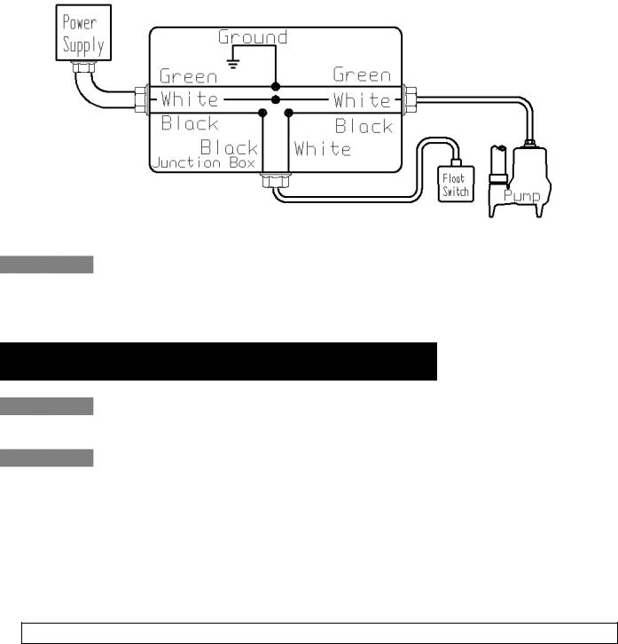
If a single phase pump is to be wired directly into a control device or junction box, and it is necessary to remove the plugs, have a certified electrician do the wiring in accordance with the National Electric Code and applicable local codes. See Fig. 6 for direct wire installation of single phase, automatic pumps.
Fig. 6 – Direct Wiring of 120V or 208-230V Single
Phase, Automatic Pumps
For 208-230V installations: Install a double pole disconnect near the pump installation. One side of the line going to the pump is always “hot”, whether the float switch is in the “On” or the “Off” position. Use of a double pole disconnect will allow both hot legs to be de-energized.
5. Maintenance
Risk of electric shock. Always disconnect the pump from the power source before handling or making adjustments.
Always disconnect the pump from power source before handling. This guide is designed to help identify reasons for potential operating problems. It is not a service guide. Dismantling of pump voids warranty. Servicing of pump other than simple cleaning of pump inlet or impeller should be referred to the factory or its authorized service centers.
1.Submersible Models: Submersible pump models have sealed permanently lubricated bearings and require no additional lubrication.
2.Pump should be checked frequently for debris and/or build up which may interfere with pump or float switch operation. The float must be able to move freely through its complete travel without any restrictions. Pour enough water into the sump to activate the pump periodically (at least every 3 months) when not normally in use to verify proper function.
NOTE: The manufacturer assumes no responsibility for damage or injury due to disassembly in the field.
©Copyright 2012 Liberty Pumps Inc. All rights reserved
8

6. Troubleshooting
|
Problem |
|
|
|
Cause |
|
|
Correction |
|
|
|
|
|
|
|
|
|||
|
|
|
|
Blown fuse or other interruption of |
|
|
Check that the unit is securely plugged in. |
|
|
|
|
|
|
|
|
Have an electrician check all wiring for proper |
|
||
|
|
|
|
|
power; improper voltage. |
|
|
connections and adequate voltage and |
|
|
|
|
|
|
|
|
|
capacity. |
|
|
|
|
|
|
Switch is unable to move to the |
|
|
Position the pump or switch so that it has |
|
Pump will not run. |
|
|
|
“turn on” position due to |
|
|
adequate clearance for free operation. |
|
|
|
|
|
interference with the side of basin |
|
|
|
|
||
|
|
|
|
|
or other obstruction |
|
|
|
|
|
|
|
|
|
Insufficient liquid level. |
|
|
Make sure the liquid level is allowed to rise |
|
|
|
|
|
|
|
enough to activate switch(s). |
|
||
|
|
|
|
|
|
|
|
|
|
|
|
|
|
|
Defective switch. |
|
|
Remove and replace switch. |
|
|
|
|
|
|
|
|
|
|
|
|
|
|
|
Switch(s) unable to move to the |
|
|
|
|
|
Pump will not turn |
|
|
|
“turn off” position due to |
|
|
Position the pump or switch so that it has |
|
|
|
|
|
interference with the side of basin |
|
|
adequate clearance for free operation. |
|
||
off. |
|
|
|
or other obstacle. |
|
|
|
|
|
|
|
|
|
|
Defective switch. |
|
|
Remove and replace switch. |
|
|
|
|
|
|
|
|
|
|
|
|
|
|
|
|
|
|
|
Check the discharge line for foreign material, |
|
|
|
|
|
Discharge is blocked or restricted. |
|
|
including ice if the discharge line passes |
|
|
|
|
|
|
|
|
|
|
through or into cold areas. |
|
|
|
|
|
|
Check valve is stuck closed or |
|
|
Remove check valve(s) and examine for |
|
|
|
|
|
|
installed backwards. |
|
|
freedom of operation and proper installation. |
|
Pump runs or hums, |
|
Gate or ball valve is closed. |
|
|
Open gate or ball valve. |
|
|||
but does not pump. |
|
|
Total lift is beyond pump's |
|
|
Try to route piping to a lower level. If not |
|
||
|
|
|
|
|
|
possible, a larger pump may be required. |
|
||
|
|
|
|
|
capability. |
|
|
|
|
|
|
|
|
|
|
|
Consult the factory. |
|
|
|
|
|
|
|
|
|
|
|
|
|
|
|
|
|
|
|
|
|
|
|
|
|
|
Pump impeller is jammed or volute |
|
|
Remove the pump from the basin. Detach the |
|
|
|
|
|
|
|
|
pump base and clean the area around the |
|
||
|
|
|
|
|
casing is plugged. |
|
|
|
|
|
|
|
|
|
|
|
impeller. Reassemble and reinstall. |
|
|
|
|
|
|
|
|
|
|
|
|
|
|
|
|
|
|
|
|
|
|
Pump runs |
|
|
|
Check valve was not installed, is |
|
|
Remove check valve(s) and examine for |
|
|
|
|
|
stuck open or is leaking. |
|
|
freedom of operation and proper installation. |
|
||
periodically when |
|
|
|
|
|
|
|||
fixtures are not in |
|
|
|
Fixtures are leaking. |
|
|
Repair fixtures as required to eliminate leakage. |
|
|
use. |
|
|
|
|
|||||
|
|
|
|
|
|
|
|
||
|
|
|
|
|
|
|
|
|
|
|
|
|
|
Foreign objects in the impeller |
|
|
Remove the pump from the basin. Detach the |
|
|
|
|
|
|
|
|
pump base and clean the area around the |
|
||
|
|
|
|
|
cavity. |
|
|
|
|
|
|
|
|
|
|
|
impeller. Reassemble and reinstall. |
|
|
|
|
|
|
|
|
|
|
|
|
|
|
|
|
|
Broken impeller. |
|
Consult the factory for information regarding |
|
|
Pump operates |
|
|
|
|
replacement of impeller. |
|
|||
|
|
|
|
|
|
|
|||
noisily. |
|
|
|
|
|
|
|
|
|
|
|
|
Worn bearings. |
|
|
Return pump to the factory or authorized repair |
|
||
|
|
|
|
|
|
||||
|
|
|
|
|
|
station for repair. |
|
||
|
|
|
|
|
|
|
|
|
|
|
|
|
|
|
|
|
|
|
|
|
|
|
|
|
Piping attachments to building are |
|
|
Replace a portion of the discharge line with |
|
|
|
|
|
|
too rigid. |
|
|
rubber hose or connector. |
|
©Copyright 2012 Liberty Pumps Inc. All rights reserved
9
 Loading...