

LG SR906SB Owner’s Manual

OWNER’S MANUAL
5.1ch SURROUND COMPACT RECEIVER SYSTEM
Please read this manual carefully before operating
your set and retain it for future reference.
SR906SB (SR906SB, SH96SB-F/S/C, SH95TA-W)
P/NO : MFL67227707

Getting Started 3
Safety Information
CAUTION
RISK OF ELECTRIC SHOCK
DO NOT OPEN
CAUTION: TO REDUCE THE RISK OF ELECTRIC
SHOCK DO NOT REMOVE COVER (OR BACK) NO
USER-SERVICEABLE PARTS INSIDE REFER SERVICING
TO QUALIFIED SERVICE PERSONNEL.
This lightning ash with arrowhead
symbol within an equilateral
triangle is intended to alert the
user to the presence of uninsulated
product’s enclosure that may be of su cient
magnitude to constitute a risk of electric shock to
persons.
instructions in the literature accompanying the
product.
WARNING: TO PREVENT FIRE OR ELECTRIC SHOCK
HAZARD, DO NOT EXPOSE THIS PRODUCT TO RAIN
OR MOISTURE.
WARNING: Do not install this equipment in a
con ned space such as a book case or similar unit.
CAUTION: Do not block any ventilation openings.
Install in accordance with the manufacturer’s
instructions.
Slots and openings in the cabinet are provided for
ventilation and to ensure reliable operation of the
product and to protect it from over heating. The
openings shall be never be blocked by placing
the product on a bed, sofa, rug or other similar
surface. This product shall not be placed in a builtin installation such as a bookcase or rack unless
proper ventilation is provided or the manufacturer’s
instruction has been adhered to.
dangerous voltage within the
The exclamation point within an
equilateral triangle is intended
to alert the user to the presence
of important operating and
maintenance (servicing)
CAUTION concerning the Power Cord
Most appliances recommend they be placed upon
a dedicated circuit;
That is, a single outlet circuit which powers only
that appliance and has no additional outlets or
branch circuits. Check the speci cation page of this
owner’s manual to be certain. Do not overload wall
outlets. Overloaded wall outlets, loose or damaged
wall outlets, extension cords, frayed power cords, or
damaged or cracked wire insulation are dangerous.
Any of these conditions could result in electric
shock or re. Periodically examine the cord of your
appliance, and if its appearance indicates damage
or deterioration, unplug it, discontinue use of the
appliance, and have the cord replaced with an
exact replacement part by an authorized service
center. Protect the power cord from physical or
mechanical abuse, such as being twisted, kinked,
pinched, closed in a door, or walked upon. Pay
particular attention to plugs, wall outlets, and
the point where the cord exits the appliance. To
disconnect power from the mains, pull out the
mains cord plug. When installing the product,
ensure that the plug is easily accessible.
This device is equipped with a portable battery or
accumulator.
Safety way to remove the battery or the
battery from the equipment: Remove the
old battery or battery pack, follow the steps
in reverse order than the assembly. To prevent
contamination of the environment and bring on
possible threat to human and animal health, the
old battery or the battery put it in the appropriate
container at designated collection points. Do
not dispose of batteries or battery together with
other waste. It is recommended that you use
local, free reimbursement systems batteries and
accumulators. The battery shall not be exposed to
excessive heat such as sunshine, re or the like.
CAUTION: The apparatus shall not be exposed to
water (dripping or splashing) and no objects lled
with liquids, such as vases, shall be placed on the
apparatus.
1
Getting Started

Table of Contents4
Table of Contents
1 Getting Started
3 Safety Information
6 Introduction
6 – Supplied Accessories
6 – Required cables
7 Remote control
7 – Battery Installation
7 – About the remote control modes
7 – To control the RECEIVER
9 – To control the PLAYER (Blu-ray disc
player, DVD player, DVD recorder, etc.)
9 – To control the TV
10 Front panel
11 Rear panel
2 Connecting
12 Positioning the system
13 Speaker Connection
13 – Attaching the speakers to the receiver
14 Connecting to Your TV
14 Connecting components with HDMI jack
16 – What is SIMPLINK?
16 – ARC (Audio Return Channel) function
16 Connecting components with digital
audio jacks
16 – Optical digital audio connection
17 – Coaxial digital audio connection
17 Connecting component with analog audio
jacks
17 Connecting the portable device
18 Connecting the antennas
18 Connecting the optimizer microphone
18 Connecting the USB device
18 Connecting the iPod
3 System Setting
19 Calibrating the appropriate settings
automatically (Auto Sound Calibration)
19 – Before performing Auto Sound
Calibration
19 – Performing Auto Sound Calibration
20 – Turning the Auto Sound Calibration
on/off
21 Settings and adjustments using the
SETUP menu
21 – SETUP confi guration
21 – TESTTONE menu
22 – LEVEL menu
22 – DISTANCE menu
22 – A/V SYNC menu (Adjusting the audio
delay)
23 – DRC menu
23 – SET HDMI menu (HDMI Standby Pass
Trough)
23 – AUTO CAL menu
23 – RESET menu

Table of Contents 5
4 Operating
24 Selecting the input source
24 Enjoying sound/images from the
components connected to the receiver
24 – Enjoying Blu-ray Disc/DVD
25 – Enjoying a satellite tuner or set top box
25 – Enjoying TV
25 – Enjoying a game console, etc
26 – Enjoying a CD player, etc
26 – Enjoying a VCR, etc
26 – Enjoying a portable device (MP3
player, etc.)
26 – Enjoying the USB or iPod connected
to the IPod/USB Port
27 Adjusting the speaker levels
27 Enjoying various sound mode
28 Listening to FM/AM radio
28 – Automatic tuning
28 – Manual tuning
28 – Improving poor FM reception
28 – Presetting radio stations
28 – Tuning to preset stations
29 – Deleting the preset stations
29 – Deleting all the preset stations
29 Playing back components with one-touch
operation (One-Touch Play)
30 Enjoying the TV sound from the speakers
connected to the receiver (System Audio
Control)
30 Turning off the receiver with the TV
(System Power Off)
31 Enjoying the TV sound via an HDMI
connection (Audio Return Channel)
31 Adjusting the audio delay
31 DOLBY DRC (Dynamic Range Control)
32 Using the Sleep Timer
32 Displaying the fi le information
33 Playing music fi les using the USB device
33 – Basic Operation
33 – Playing repeatedly or randomly
33 – Music fi le requirement
33 – USB device requirement
34 Playing the iPod
35 Controlling a TV with the Supplied
Remote Control
35 – Setting up the remote to control your TV
5 Troubleshooting
36 Troubleshooting
6 Appendix
38 Manufacturer code list
42 Trademarks and Licenses
43 Specifi cations
45 Maintenance
45 – Handling the Unit
1
2
3
4
5
6
7
Getting Started6
Introduction
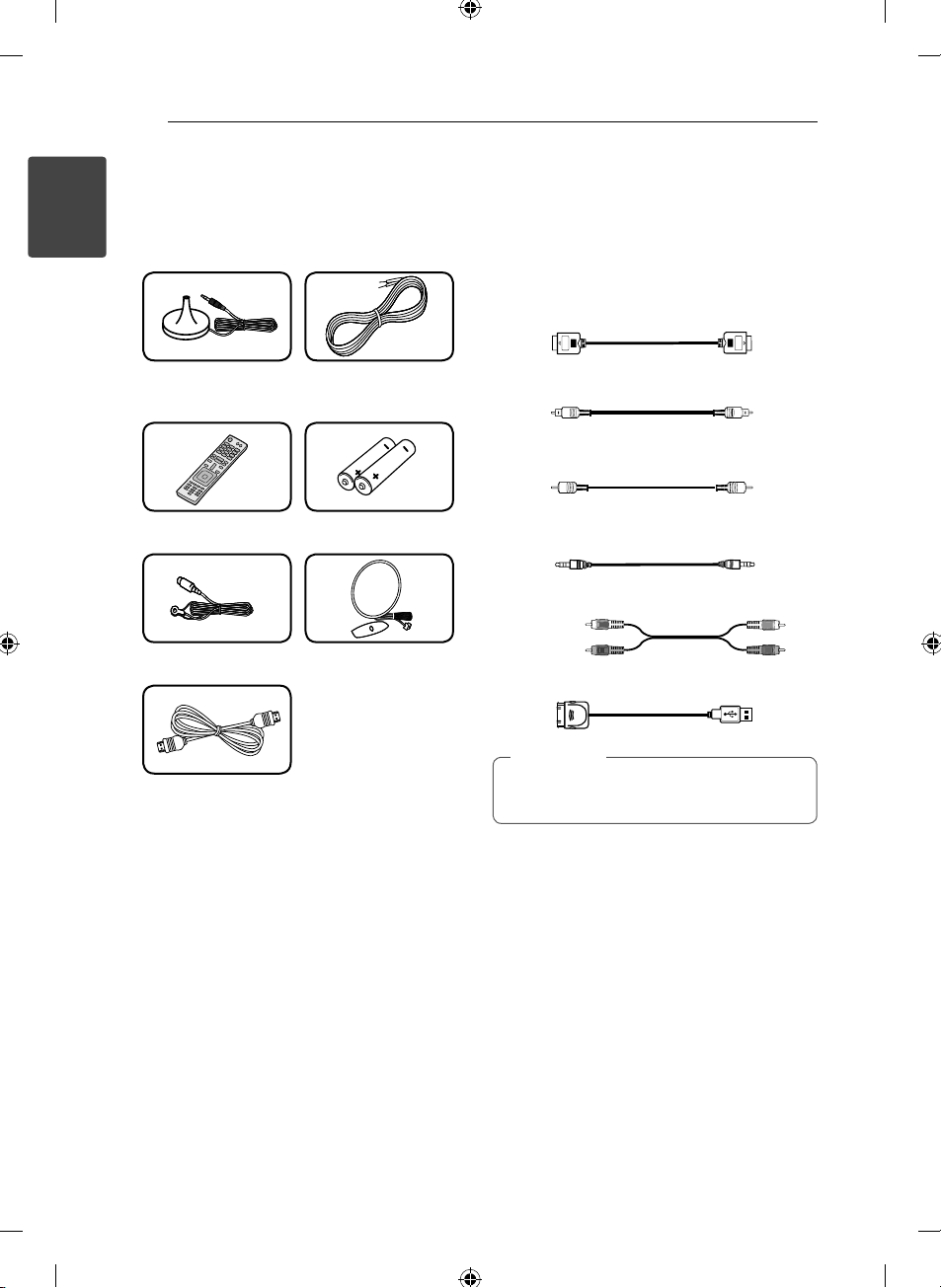
Supplied Accessories
1
Getting Started
Optimizer microphone
(1)
Remote control (1) Batteries (2)
FM antenna (1) AM antenna (1)
Speaker cables (6)
Required cables
The hookup diagrams on the subsequent pages
assume the use of the following connection cables.
You must purchase the connection cables
separately if necessary.
HDMI cable (Type A, High speed HDMI™ cable or
Type A, High speed HDMI™ cable with Ethernet)
Optical digital audio cable
Coaxial digital audio cable
Portable cable
Analog audio cable
White (L)
Red (R)
iPod cable
HDMI cable (1)
Note
,
The iPod cable is included when you purchase
iPhone or iPod.
Getting Started 7
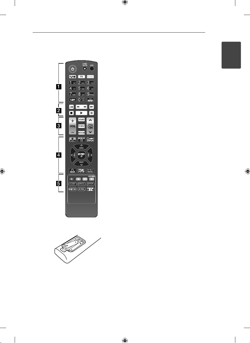
Remote control
Battery Installation
Remove the battery cover on the rear of the
Remote Control, and insert two R03 (size AAA)
batteries with 4 and 5 matched correctly.
About the remote control
modes
The remote control has a speci c operating mode
for use with each type of component. Modes are
selected by using the three RECEIVER, PLAYER, and
TV buttons on the remote control.
1. Press RECEIVER, PLAYER, or TV buttons to select
the component you want to operate.
- RECEIVER: In RECEIVER Mode, you can control
the receiver.
- PLAYER: In PLAYER Mode, you can control a
Blu-ray disc player, DVD player, DVD
recorder, etc. (For LG product only)
- TV: In TV Mode, you can control TV.
2. Referring to the following contents (pages
7-9), press the corresponding button for the
operation.
To control the RECEIVER
• • • • • • a • • • • • • • • •
(POWER): Turns the receiver on or o .
1
ARC: Outputs audio signal of the TV via an HDMI
cable (Type A, High speed HDMI™ cable or Type A,
High speed HDMI™ cable with Ethernet).
RECEIVER: Controls the receiver.
Press the corresponding button for the operation
after pressing the RECEIVER button.
INPUT buttons: Selects the input source you want
to use.
- BD: Selects the input source connected to BD IN
jack.
- DVD: Selects the input source connected to DVD
IN jack.
- STB: Selects the input source connected to STB IN
jack.
- TV: Selects the input source connected to TV IN
jack.
- GAME: Selects the input source connected to
GAME IN jack.
- CD: Selects the input source connected to CD IN
jack.
- RADIO: Selects the FM/AM.
- VCR: Selects the input source connected to VCR
IN jack.
1
Getting Started

Getting Started8
- PORTABLE: Selects the input source connected to
PORT. IN jack.
- IPOD/USB: Selects the input source connected to
IPOD/USB Port.
1
Getting Started
Note
,
In RECEIVER mode, the 0-9 numerical buttons
does not work.
CLEAR: Deletes all the preset stations in tuner
mode.
REPEAT (h): Plays the les repeatedly or
randomly in iPod or USB mode.
• • • • • • b • • • • • • • • •
c/v
C/V
chapter / track / le.
Z
d
M
• • • • • • c • • • • • • • • •
VOL +/-: Adjusts speaker volume.
SOUND: Selects a sound e ect mode.
MUTE (
the button again to restore the sound.
• • • • • • d • • • • • • • • •
INFO/DISPLAY (m): Displays information of music
les or digital input source.
ENTER (b): Acknowledges menu selection.
PRESET +/-: Selects a preset stations in tuner
mode.
TUNING +/-: Tunes in the desired radio station in
tuner mode.
BACK (x): Returns to the upper menu of any
displayed menu.
DISC MENU: Returns to the upper menu in iPod
mode.
(SCAN): Searches backward or forward.
(SKIP): Goes to the next or previous
(STOP): Stops playback.
(PLAY): Starts playback.
(PAUSE): Pauses playback.
): Turns o the sound temporarily. Press
• • • • • • e • • • • • • • • •
MONO/STEREO: Selects mono/ stereo in FM mode.
SLEEP: Sets the system to turn o automatically at
a speci ed time.
AUTO CAL.: Performs the Auto Sound Calibration.
SETUP: Moves to the [SETUP] menu.
DOLBY DRC: Sets the Dolby DRC (Dynamic Range
Control).
AV SYNC.: Delays the sound output using this
function when the image is slower than the sound.
SPEAKER LEVEL: Sets the sound level of desired
speaker.
Getting Started 9
To control the PLAYER (Bluray disc player, DVD player,
DVD recorder, etc.)
• • • • • • a • • • • • • • • •
(POWER): Turns the player on or o .
1
(OPEN/CLOSE): Opens and closes the disc tray.
B
PLAYER: Controls the PLAYER (Blu-ray disc player,
DVD player, DVD recorder, etc.).
Press the corresponding button for the operation
after pressing the PLAYER button.
0-9 numerical buttons: Selects numbered options
in a menu or inputs letters in the keypad menu.
CLEAR: Removes a mark on the search menu or a
number when setting the password.
REPEAT (h): Repeats a desired section or
sequence.
• • • • • • b • • • • • • • • •
c/v
C/V
chapter / track / le.
Z
d
M
• • • • • • d • • • • • • • • •
HOME (n): Displays or exits the [Home Menu].
INFO/DISPLAY (m): Displays or exits On-Screen
Display.
Direction buttons (
option in the menu.
ENTER (b): Acknowledges menu selection.
BACK (x): Returns to the upper menu of any
displayed menu.
TITLE/POP UP: Displays the DVD title menu or BDROM’s pop-up menu, if available.
DISC MENU: Accesses menu on a disc.
• • • • • • e • • • • •
Colored (R, G, Y, B) buttons:
Displays an operation guide on the TV screen
when the color buttons are available. Follow the
operation guide to perform a selected operation.
(SCAN): Searches backward or forward.
(SKIP): Goes to the next or previous
(STOP): Stops playback.
(PLAY): Starts playback.
(PAUSE): Pauses playback.
A/D/W/S
): Selects an
To control the TV
• • • • • • a • • • • • • • • •
(POWER): Turns the TV on or o .
1
0-9 numerical buttons: Selects numbered options
in a menu or inputs letters in the keypad menu.
• • • • • • c • • • • • • • • •
VOL +/-: Adjusts the volume.
TV INPUT: Selects the TV’s source.
MUTE (
the button again to restore the sound.
PR/CH
): Turns o the sound temporarily. Press
: Selects the channel.
W/S
Note
,
The above explanation is intended to serve
as an example only. Therefore, depending on
the component, the above operation may not
be possible or may operate di erently than
described. In that case, use the remote control
supplied with the component.
1
Getting Started
Getting Started10
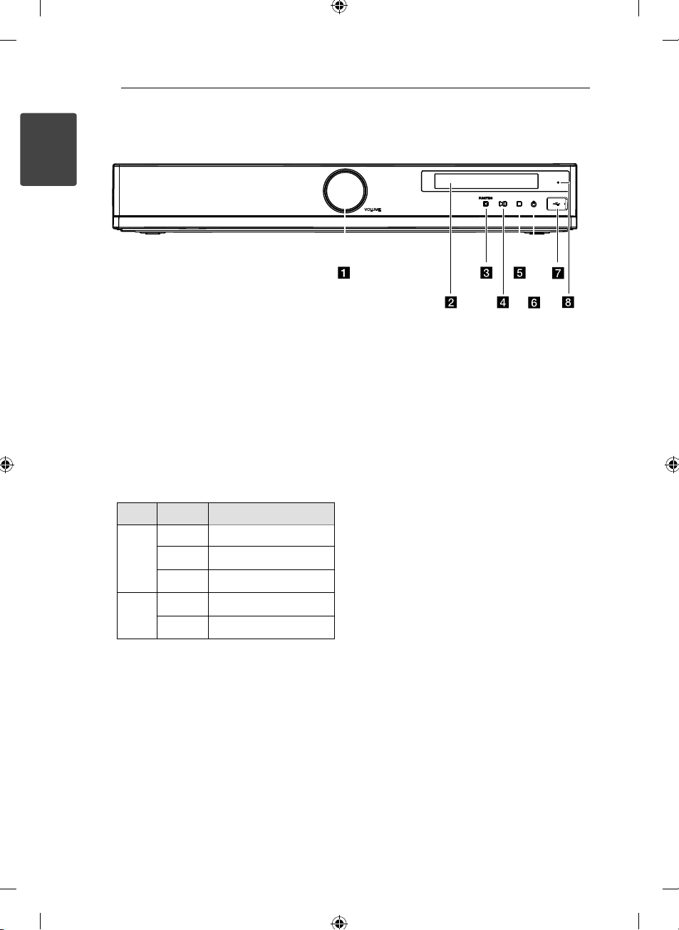
Front panel
1
Getting Started
Volume Control
a
Adjusts speaker volume.
Display Window
b
Shows the current status of the receiver.
FUNCTION
c
Selects the input source you want to use.
(PLAY / PAUSE)
d dM
Starts or pauses playback in iPod or USB mode.
(STOP)
e Z
Mode To Do this
USB Pause Press Z (STOP).
Playback Press dM (PLAY / PAUSE).
Stop Press Z (STOP) twice.
IPOD Pause Press Z (STOP).
Playback Press dM (PLAY / PAUSE).
(POWER)
f 1
Turns the receiver on or o .
IPod/USB Port
g
Connects an IPod/USB device to IPod/USB Port.
STAND BY/HDMI THRU indicator
h
Lights up as follows:
- Red : The receiver is in standby mode.
- Blue : The receiver is in standby mode, and
control for HDMI is set to on.
- Lights o when the receiver is turned on.
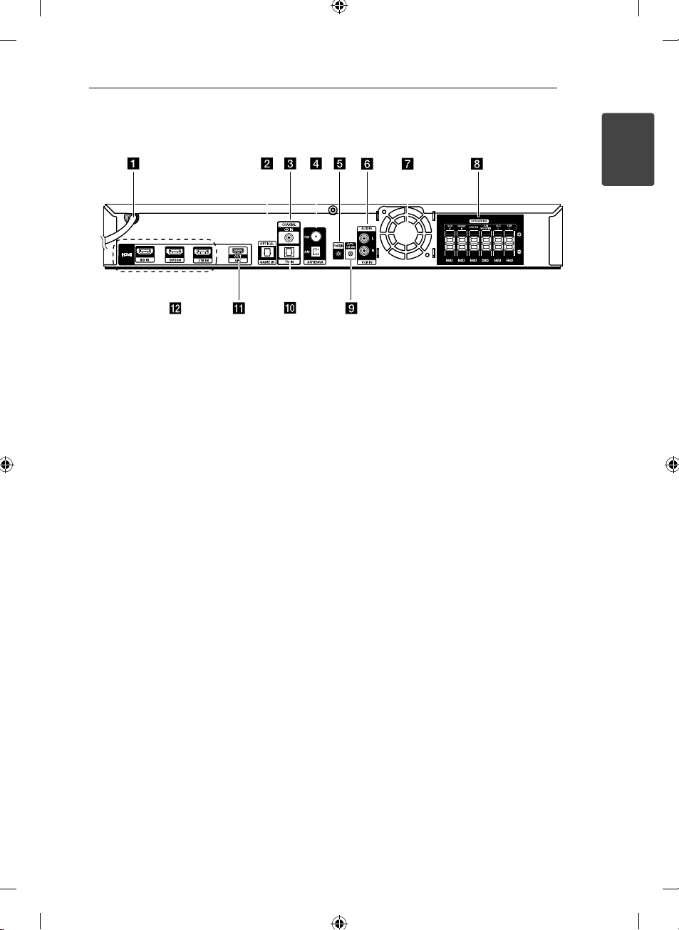
Rear panel
Getting Started 11
1
Getting Started
AC power cord
a
OPTICAL GAME IN
b
Connects to other components with an optical
digital audio output.
COAXIAL CD IN
c
Connects to other components with a coaxial
digital audio output.
Antenna connectors
d
Connects to the FM wire antenna and AM loop
antenna.
PORT. IN
e
Connects to a portable device (MP3 player, etc)
to PORT. IN jack.
AUDIO VCR IN
f
Connects to the components with analog
audio out jacks.
Cooling fan
g
Speakers connectors
h
Connects to the speakers and subwoofer.
AUTO CAL MIC
i
Connects to the optimizer microphone for the
Auto Sound Calibration function.
OPTICAL TV IN
j
Connects to the TV with an optical digital
audio output.
HDMI OUT
k
Connects to a TV. When the TV is compatible
with ARC (Audio Return Channel) function,
you can output the TV sound via the speakers
connected to the receiver without connecting
the analog audio cable or the optical digital
audio cable.
HDMI IN
l
Connects to a DVD player, satellite tuner, set
top box, Blu-ray Disc player, etc.. The image is
output to a TV or a projector while the sound
can be output from a TV or/and speakers
connected to this receiver.
Connecting12
A
B
D
E
F
A
A
A
A
A
G
C
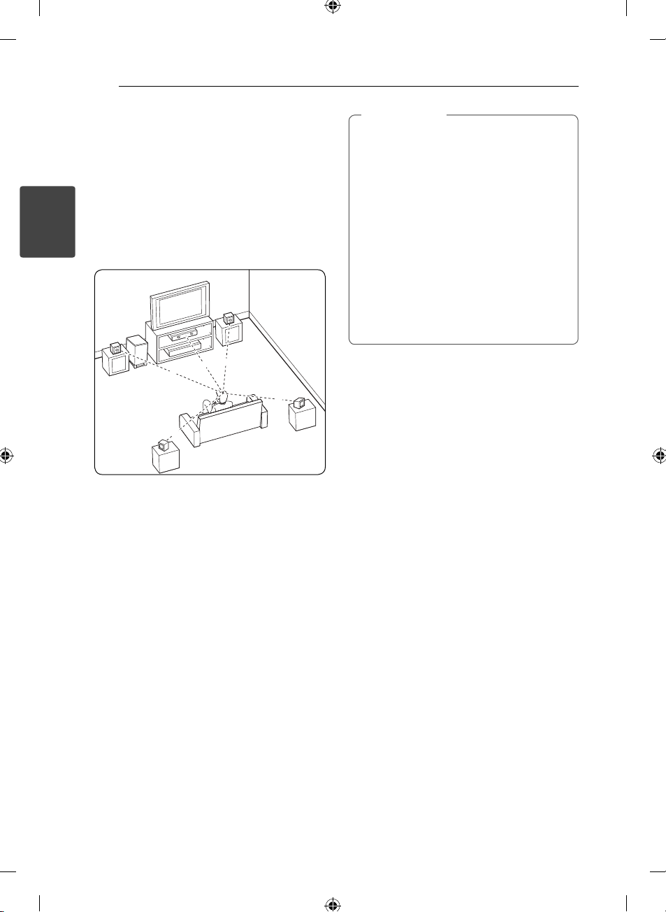
Positioning the system
The following illustration shows an example of
positioning the system. Note that the illustrations
in these instructions di er from the actual unit for
explanation purposes.
For the best possible surround sound, all the
speakers other than the subwoofer should be
placed at the same distance from the listening
2
position (A).
Connecting
Caution
>
Be careful to make sure children not to put
their hands or any objects into the *speaker
duct.
*Speaker duct: A hole for plentiful bass
sound on speaker cabinet (enclosure).
Place the center speaker at a safe distance
from the child’s reach.
Otherwise it may result in the speaker falling
down and causing personal injury and/or
property damage.
The speakers contain magnetic parts, so
colour irregularity may occur on the CRT
TV screen or PC monitor screen. Please use
the speakers away from the TV screen or PC
monitor screen.
Front left speaker (L)/ B Front right
A
speaker (R):
Place the front speakers to the sides of the monitor
or screen and as ush with the screen surface as
possible.
Center speaker:
C
Place the center speaker above or below the
monitor or screen.
Surround left speaker (L)/ E Surround right
D
speaker (R):
Place these speakers behind your listening position,
facing slightly inwards.
Subwoofer:
F
The position of the subwoofer is not so critical,
because low bass sounds are not highly directional.
But it is better to place the subwoofer near the
front speakers. Turn it slightly toward the center of
the room to reduce the wall re ections.
Receiver
G
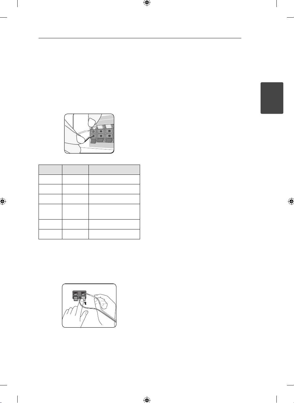
Speaker Connection
Attaching the speakers to the
receiver
1. Connect speaker wires to the receiver.
Each speaker wire is color-coded. Use matching
color wires for corresponding speakers.
Color Speaker Position
Grey Rear Rear right
Blue Rear Rear left
Green Center Center
Orange
Red Front Front right
White Front Front left
Sub
woofer
Any front position
Connecting 13
2
Connecting
2. Connect the speaker wire to the terminal on the
speaker.
Make sure the wire marked black goes in to the
terminal marked “–” (minus) and the other wire
goes in to the terminal marked “+” (plus).
Connecting14
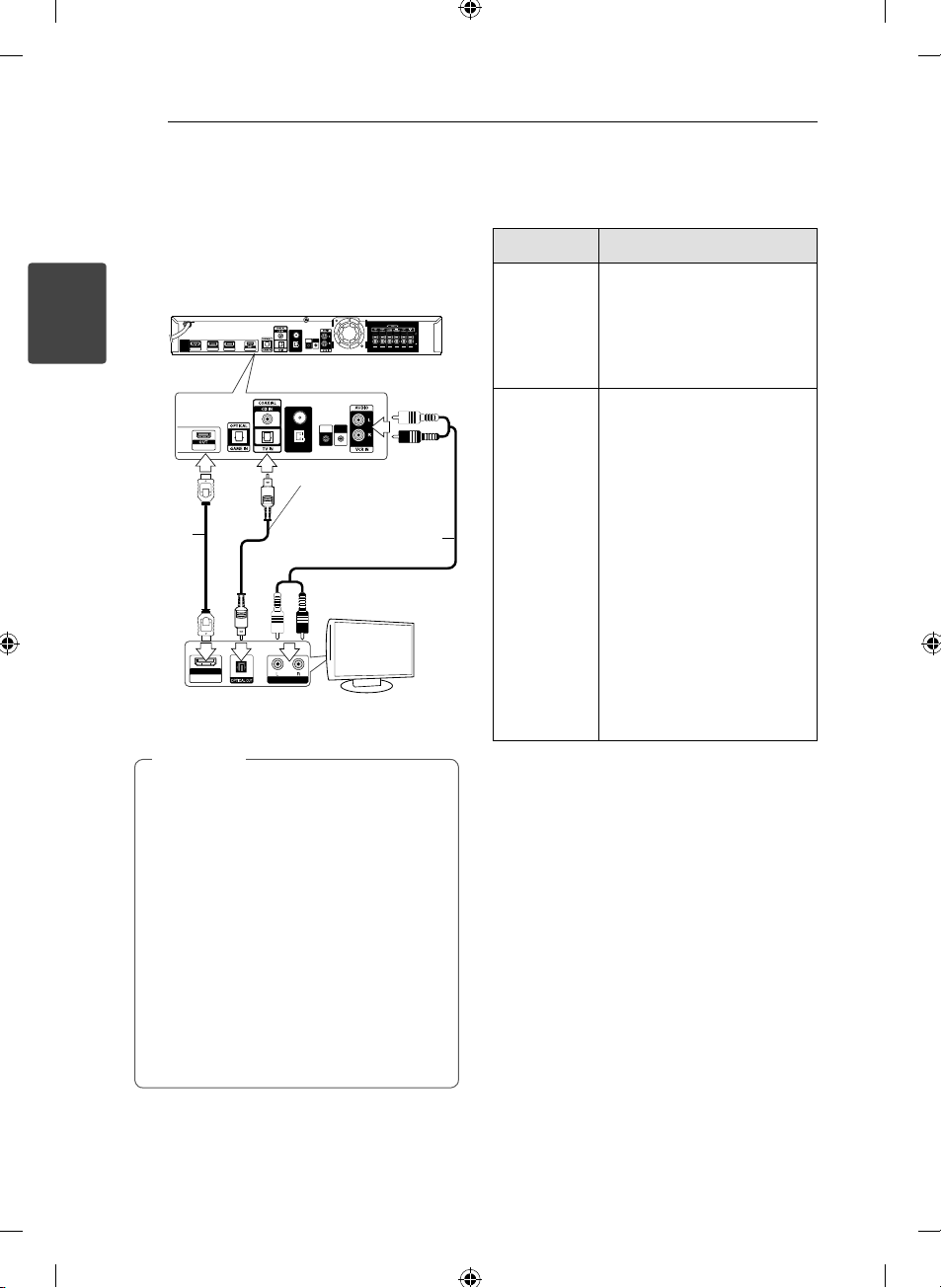
Connecting to Your TV
You can watch the selected input image when you
connect the HDMI OUT jack to a TV.
Before connecting the cables, be sure to disconnect
the AC power cord.
FM
AUTO
PORT.IN
CAL MIC
HDMI
BD IN
DVD IN
2
STB IN
Connecting
ARC
HDMI
C
cable
HDMI IN
ARC
Set the TV’s source to HDMI (refer to TV’s Owner’s
manual).
Note
,
Turn o the power to all components
before making any connections.
When connecting optical digital audio
cables, insert the cable plugs straight in
until they click into place.
Do not bend or tie optical digital audio
cables.
When you use ARC (Audio Return Channel)
function. the audio signal is output from the
TV to the unit. When the TV is compatible
with ARC (Audio Return Channel) function,
the TV sound will output from the speakers
connected to the unit. Be sure to activate
the ARC (Audio Return Channel) function by
pressing ARC.
ARC
AM
Rear of the receiver
FM
AUTO
PORT.IN
CAL MIC
AM
Optical digital
B
audio cable
Analog audio cable
A
AUDIO OUT
It is not necessary to connect all the cables.
Connect the cables according to the jacks of your
components.
Connect To
Analog
A
audio cable
or B Optical
digital audio
cable
output the TV sound via the
speakers connected to the
receiver.
Be sure to turn o the TV's
volume or activate the TV's
muting function.
HDMI
L
R
C
cable (Type
A, High speed
HDMI™ cable
or Type A,
High speed
HDMI™ cable
with Ethernet)
output the image to a TV while
the sound can be output from a
TV or/and speakers connected
to the receiver.
When the TV is compatible with
ARC (Audio Return Channel)
function, you can output the
TV sound via the speakers
connected to the receiver
without connecting A Analog
audio cable or B Optical digital
TV
audio cable. For details, see
"Enjoying the TV sound via an
HDMI connection (Audio Return
Channel)" (page 31).
Be sure to turn o the TV's
volume or activate the TV's
muting function.
Connecting
components with
HDMI jack
You can enjoy the image and sound from your
component through this connection.
It is not necessary to connect all the cables.
Connect the cables according to the jacks of your
components.
Connect the HDMI OUT ARC jack on the receiver
to the HDMI IN jack on a HDMI compatible TV or
monitor. Connect the HDMI BD IN, HDMI DVD
IN, HDMI STB IN jack on the receiver to your
components with HDMI OUT jack using a HDMI
cable (Type A, High speed HDMI™ cable or Type A,
High speed HDMI™ cable with Ethernet).
 Loading...