

LG PF-43A20 Schematic
COLOR TV
SERVICE MANUAL
CAUTION
BEFORE SERVICING THE CHASSIS,
READ THE SAFETY PRECAUTIONS IN THIS MANUAL.
CHASSIS : MP-87B
MODEL : PF-43A20

- 2 -
CONTENTS
Contents .......................................................................................................... 2
Safety Precautions ..........................................................................................3
Servicing Precautions .................................................................................... 4
Specifications ................................................................................................. 6
Control Descriptions ...................................................................................... 8
Alignment/Test Point Location Guide...........................................................11
Adjustment......................................................................................................14
Troubleshooting.............................................................................................19
Component Location Guide.........................................................................26
Printed Circuit Board.....................................................................................27
Block Diagram................................................................................................34
Wiring Diagram...............................................................................................36
Exploded View .............................................................................................. 38
Exploded View Parts List...............................................................................39
Replacement Parts List ................................................................................ 40
SVC. Sheet .........................................................................................................

- 3 -
SAFETY PRECAUTIONS
Many electrical and mechanical parts in this chassis have special safety-related characteristics. These parts are identified by in
the Schematic Diagram and Replacement Parts List.
It is essential that these special safety parts should be replaced with the same components as recommended in this manual to
prevent X-RADIATION, Shock, Fire, or other Hazards.
Do not modify the original design without permission of manufacturer.
General Guidance
An lsolation Transformer should always be used during
the servicing of a receiver whose chassis is not isolated from
the AC power line. Use a transformer of adequate power rating
as this protects the technician from accidents resulting in
personal injury from electrical shocks.
It will also protect the receiver and it's components from being
damaged by accidental shorts of the circuitary that may be
inadvertently introduced during the service operation.
If any fuse (or Fusible Resistor) in this TV receiver is blown,
replace it with the specified.
When replacing a high wattage resistor (Oxide Metal Film
Resistor, over 1W), keep the resistor 10mm away from PCB.
Keep wires away from high voltage or high temperature parts.
Due to high vacuum and large surface area of picture tube,
extreme care should be used in handling the Picture Tube.
Do not lift the Picture tube by it's Neck.
X-RAY Radiation
Warning:
To determine the presence of high voltage, use an accurate
high impedance HV meter.
Adjust brightness, color, contrast controls to minimum.
Measure the high voltage.
The meter reading should indicate
23.5
¡ 1.5KV: 14-19 inch, 26 ¡ 1.5KV: 19-21 inch,
29.0 ¡ 1.5KV: 25-29 inch, 30.0 ¡ 1.5KV: 32 inch
If the meter indication is out of tolerance, immediate service
and correction is required to prevent the possibility of
premature component failure.
Insulation Resistance Testing
Examine the area surrounding the repaired location for damage
or deterioration, Observe that screws, parts and wires have
been returned to original positions. Afterwards, perform the
following tests and confirm the specified values in order to
verity compliance with safety standards.
Requirements of the Electricity regulations 1997 and
AS/NZS3760 : 1996
All products that are serviced must have a safety test carried
out in accordance with AS/NZS 3760 : 1996.
This equipment is double insulated so the following test should
be carried out.
Testing Equipment Required :
An insulation resistance meter with the following characteristics.
a) A measuring circuit isolated from earth
b) Nominal measuring voltage 500V DC
c) Accuracy Class 5 or better (Class 5 = accuracy of 5%)
Insulation resistance test.
During this test the power switch must in the "ON" position.
For the purpose of this test, small exposed metal parts such as
nameplates, screws or rivets which are fixed or attached to
non-conductive material in such a manner that they cannot
become live, even in the event of a failure of internal insulation,
are not required to be tested.
Confirm that the insulation resistance between the power plug
prongs and externally exposed parts of the unit (metal case,
bottom cover, RF terminals, antenna terminals, video and audio
output and input terminals, microphone jacks, earphone jacks,
oxtension speaker sockets, etc) has a minimum resistance of
1M§ .
The source of X-RAY RADIATION in this TV receiver is the
High Voltage Section and the Picture Tube.
For continued X-RAY RADIATION protection, the
replacement tube must be the same type tube as specified in
the Replacement Parts List.
VIDEO
AUDIO
75Ω
L
R
IN
OUT
LLEEGGEENNDD ::
¤ Any switch to be "ON"
during tests
¤Ł Test active and neutral to
exposed metal parts
Insulation resistance
meter
IMPORTANT SAFETY NOTICE

- 4 -
CAUTION: Before servicing receivers covered by this service
manual and its supplements and addenda, read and follow the
SAFETY PRECAUTIONS
on page 3 of this publication.
NOTE:
If unforeseen circumstances create conflict between the
following servicing precautions and any of the safety
precautions on page 3 of this publication, always follow the
safety precautions. Remember: Safety First.
General Servicing Precautions
1. Always unplug the receiver AC power cord from the AC
power source before;
a. Removing or reinstalling any component, circuit board
module or any other receiver assembly.
b. Disconnecting or reconnecting any receiver electrical plug
or other electrical connection.
c.
Connecting a test substitute in parallel with an electrolytic
capacitor in the receiver.
CAUTION: A wrong part substitution or incorrect
polarity installation of electrolytic capacitors may result
in an explosion hazard.
d. Discharging the picture tube anode.
2. Test high voltage only by measuring it with an appropriate
high voltage meter or other voltage measuring device (DVM,
FETVOM, etc) equipped with a suitable high voltage probe.
Do not test high voltage by "drawing an arc".
3. Discharge the picture tube anode only by (a) first connecting
one end of an insulated clip lead to the degaussing or kine
aquadag grounding system shield at the point where the
picture tube socket ground lead is connected, and then (b)
touch the other end of the insulated clip lead to the picture
tube anode button, using an insulating handle to avoid
personal contact with high voltage.
4. Do not spray chemicals on or near this receiver or any of its
assemblies.
5. Unless specified otherwise in this service manual, clean
electrical contacts only by applying the following mixture to
the contacts with a pipe cleaner, cotton-tipped stick or
comparable nonabrasive applicator; 10% (by volume)
Acetone and 90% (by volume) isopropyl alcohol (90%-99%
strength)
CAUTION: This is a flammable mixture.
Unless specified otherwise in this service manual, lubrication
of contacts in not required.
6. Do not defeat any plug/socket B+ voltage interlocks with
which receivers covered by this service manual might be
equipped.
7. Do not apply AC power to this instrument and/or any of its
electrical assemblies unless all solid-state device heat sinks
are correctly installed.
8. Always connect the test receiver ground lead to the
receiver chassis ground before connecting the test receiver
positive lead.
Always remove the test receiver ground lead last.
9.
Use with this receiver only the test fixtures specified in this
service manual.
CAUTION: Do not connect the test fixture ground strap to
any heatsink in this receiver.
Electrostatically Sensitive (ES) Devices
Some semiconductor (solid state) devices can be damaged
easily by static electricity. Such components commonly are
called
Electrostatically Sensitive (ES) Devices.
Examples of
typical ES devices are integrated circuits and some fieldeffect
transistors and semicounductor "chip" components. The
following techniques should be used to help reduce the
incidence of component damage caused by static by static
electricity.
1. Immediately before handling any semiconductor component
or semiconductor-equipped assembly, drain off any
electostatic charge on your body by touching a known earth
ground. Alternatively, obtain and wear a commercially
available discharging wrist strap device, which should be
removed to prevent potential shock reasons prior to
applying power to the unit under test.
2. After removing an electrical assembly equipped with ES
devices, place the assembly on a conductive surface such as
aluminum foil, to prevent electrostatic charge buildup or
exposure of the assembly.
3. Use only a grounded-tip soldering iron to solder or unsolder
ES devices.
4. Use only an anti-static type solder removal device. Some
solder removal devices not classified as "anti-static" can
generate electrical charges sufficent to demage ES devices.
5. Do not use freon-propelled chemicals. These can generate
electrical charges sufficient to damage ES devices.
6. Do not remove a repalcement ES device from its protective
package until immediately before you are ready to install it.
(Most replacement ES devices are packaged with leads
electrically shorted together by conductive foam, aluminum
foil or comparable conductive material).
7. Immediately before removing the protective material from
the ieads of a replacement ES device, touch the protective
material to the chassis or circuit assembly into which the
device will be installed.
CAUTION:Be sure no power is applied to the chassis or
circuit, and observe all other safety precautions.
8. Minimize bodily motions when handling unpackaged
replacement ES devices. (Otherwise harmless motion such
as the bruching together of your clothes fabric or the lifting
of your foot from a carpeted floor can generate static
electricity sufficient to damage an ES device.)
General Soldering Guidelines
1. Use a grounded-tip, low-wattage soldering iron and
appropriate tip size and shape that will maintan tip
temperature within the range or 500¡£F to 600¡£F.
2. Use an appropriate gauge of RMA resin-core solder
composed of 60 parts tin/40 parts lead.
3. Keep the soldering iron tip clean and well tinned.
4. Thorohly clean the surfaces to be soldered. Use a mall
wirebristle (0.5 inch, or 1.25cm) brush with a metal handle.
Do not use freon-propelled spray-on cleaners.
5. Use the following unsoldering technique
a. Allow the soldering iron tip to reach normal temperature.
(500¡£F to 600¡£F)
b. Heat the component lead until the solder melts.
c. Quickly draw the melted solder with an anti-static,
suction-type solder removal device or with solder braid.
CAUTION: Work quickly to avoid overheating the
circuiboard printed foil.
6. Use the following soldering technique.
a. Allow the soldering iron tip to reach a normal
temperature (500¡£F to 600¡£F)
b. First, hold the soldering iron tip and solder the strand
against the component lead until the solder melts.
SERVICING PRECAUTIONS

- 5 -
c. Qulckly move the soldering iron tip to the junction of the
component lead and the printed circuit foil, and hold it
there only until the solder flows onto and around both the
component lead and the foil.
CAUTION: Work quickly to avoid overheating the circuit
board printed foil.
d. Closely inspect the solder area and remove any excess
or splashed solder with a small wire-bristle brush.
IC Remove/Replacement
Some chassis circuit boards have slotted holes (oblong) through
which the IC leads are inserted and then bent flat against the
circuit foil. When holes are the slotted type, the following
technique should be used to remove and replace the IC. When
working with boards using the familiar round hole, use the
standard technique as outlined in parapraphs 5 and 6 above.
Removal
1. Desolder and straighten each IC lead in one operation by
gently prying up on the lead with the soldering iron tip as the
solder melts.
2. Draw away the melted solder with an anti-static suctiontype solder removal device (or with solder braid) before
removing the IC.
Replacement
1. Carefully insert the replacement IC in the circuit boare.
2. Carefully bend each IC lead against the circuit foil pad and
solder it.
3. Clean the soldered areas with a small wire-bristle brush.
(It is not necessary to reapply acrylic coating to the areas).
"Small-Signal" Discrete Transistor
Removal/Replacement
1. Remove the defective transistor by clipping its leads as
close as possible to the component body.
2. Bend into a "U" shape the end of each of three leads
remaining on the circuit board.
3. Bend into a "U" shape the replacement transistor leads.
4. Connect the replacement transistor leads to the
corresponding leads extending from the circuit board and
crimp the "U" with long nose pliers to insure metal to metal
contact then solder each connection.
Power Output, Transistor Device
Removal/Replacement
1. Heat and remove all solder from around the transistor leads.
2. Remove the heatsink mounting screw (if so equipped).
3. Carefully remove the transistor from the heat sink of the
circuit board.
4. Insert new transistor in the circuit board.
5. Solder each transistor lead, and clip off excess lead.
6. Replace heatsink.
Diode Removal/Replacement
1. Remove defective diode by clipping its leads as close as
possible to diode body.
2. Bend the two remaining leads perpendicula y to the circuit
board.
3. Observing diode polarity, wrap each lead of the new diode
around the corresponding lead on the circuit board.
4. Securely crimp each connection and solder it.
5. Inspect (on the circuit board copper side) the solder joints of
the two "original" leads. If they are not shiny, reheat them
and if necessary, apply additional solder.
Fuse and Conventional Resistor
Removal/Replacement
1. Clip each fuse or resistor lead at top of the circuit board
hollow stake.
2. Securely crimp the leads of replacement component around
notch at stake top.
3. Solder the connections.
CAUTION: Maintain original spacing between the replaced
component and adjacent components and the circuit board
to prevent excessive component temperatures.
Circuit Board Foil Repair
Excessive heat applied to the copper foil of any printed circuit
board will weaken the adhesive that bonds the foil to the circuit
board causing the foil to separate from or "lift-off" the board.
The following guidelines and procedures should be followed
whenever this condition is encountered.
At IC Connections
To repair a defective copper pattern at IC connections use the
following procedure to install a jumper wire on the copper
pattern side of the circuit board. (Use this technique only on IC
connections).
1. Carefully remove the damaged copper pattern with a sharp
knife. (Remove only as much copper as absolutely
necessary).
2. carefully scratch away the solder resist and acrylic coating
(if used) from the end of the remaining copper pattern.
3. Bend a small "U" in one end of a small gauge jumper wire and
carefully crimp it around the IC pin. Solder the IC connection.
4. Route the jumper wire along the path of the out-away
copper pattern and let it overlap the previously scraped end
of the good copper pattern. Solder the overlapped area and
clip off any excess jumper wire.
At Other Connections
Use the following technique to repair the defective copper
pattern at connections other than IC Pins. This technique
involoves the installation of a jumper wire on the component
side of the circuit board.
1. Remove the defective copper pattern with a sharp knife.
Remove at least 1/4 inch of copper, to ensure that a
hazardous condition will not exist if the jumper wire opens.
2. Trace along the copper pattern from both sides of the
pattern break and locate the nearest component that is
directly connected to the affected copper pattern.
3. Connect insulated 20-gauge jumper wire from the lead of
the nearest component on one side of the pattern break to
the lead of the nearest component on the other side.
Carefully crimp and solder the connections.
CAUTION: Be sure the insulated jumper wire is dressed so
the it does not touch components or sharp edges.
- 6 -
SPECIFICATIONS
NOTE : Specifications and others are subject to change without notice for improvement.
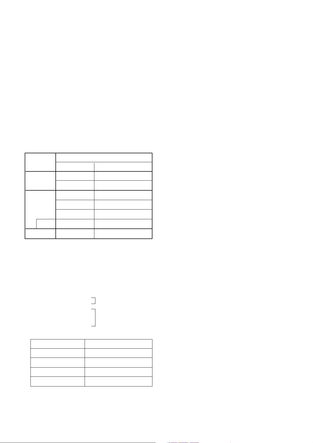
¡ Video input system:
Multi 26 System
(Refer to Table 1)
¡ Intermediate Frequency
Vision IF : 38.0MHz
Color IF : 33.57MHz ¡ SECAM : 38.0-4.25MHz
34.42MHz(M) 38.0-4.40625MHz
Sound IF : 32.5MHz(B/G)
32.0MHz(I)
31.5MHz(D/K,K1)
33.5MHz(M)
¡ Tuning range
¡ OSD (On Screen Display):
Menu Method
¡ Antenna input impedance: VHF/UHF 75ohm, Unbalanced
¡ Voice coil impedance : 8 ohm
¡ External connections :
S-VIDEO (Super Video)
A/V in : 1 pair
S-VIDEO (Super Video)
Scart(Full)
A/V in : 1 pair
A/V out : 1 pair
¡ Power requirements :
100-270 Vac, 50/60HZ
¡ Power consumption :
210 Wmax.
¡ Tuning system :
VS (Voltage Synthesizer)
100 Program Memory
¡ Sound output :
25 W max. X 2 way: (4 speaker)
Dual / Stereo : A2, NICAM
¡ Local button :
Menu, OK, TV/AV, POWER
Volume up(+), down(-)
Program up(+), down(-)
¡ Function :
Auto Program
Manual Program
Auto Sleep
ON/OFF TIMER
CATV/Hyper band
Teletext (TOP/FLOF/LIST)
PIP (Picture In Picture)
Child Lock :
In the Lock On state the TV can only be operated by the
remote controller.
If any button on the front panel is pressed, "CHILD LOCK ON" is
displayed on the screen but the button's function is not
performed.
To cancel of this mode, select lock off with menu button on
remote controller only.
¡ Features
Picture quality improvement circuit
- YNR (Luminance Noise Reduction)
- Picture Outline Compensation
Band
VHF-Low
VHF-High
UHF
PAL/SECAM-B/G
For TV
Ch 2-4
Ch 5-12
Ch 21-69
For CATV
S1’-S3’, S1
S2-S10
S11-S20
S21-S41
Hyper
Front
Rear
Video in/out
Audio in (2 way)
Audio out (2 way)
R. G. B in
Specifications
1Vp-p¡ 3dB, 75ohm
0.5Vrms¡ 3dB, over 10Kohm
0.5Vrms¡ 3dB, below 1Kohm
0.7Vp-p¡ 3dB
(
- 7 -
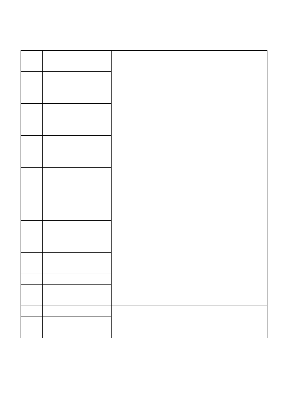
Table 1 : Receiving System (26 System)
No
1
2
3
4
5
6
7
8
9
10
11
12
13
14
15
16
17
18
19
20
21
22
23
24
25
26
Receiving System
PPAALL--BB
PPAALL--GG
PPAALL--II
PPAALL--DD
PPAALL--KK
SSEECCAAMM--BB
SSEECCAAMM--GG
SSEECCAAMM--DD
SSEECCAAMM--KK
SSEECCAAMM--KK11
NNTTSSCC--MM
NTSC 4.43/5.5MHZ
NTSC 4.43/6.0MHZ
NTSC 4.43/6.5MHZ
SECAM-I (6.0MHZ)
SECAM-L (Video In)
NTSC 3.58/4.5MHZ/50HZ
PAL 5.5MHZ/60HZ
PAL 6.0MHZ/60HZ
PAL 6.5MHZ/60HZ
SECAM 5.5MHZ/60HZ
SECAM 6.0MHZ/60HZ
SECAM 6.5MHZ/60HZ
NTSC 3.58/5.5MHZ
NTSC 3.58/6.0MHZ
NTSC 3.58/6.5MHZ
Receiving Channel
VVHHFF BBaanndd
PAL/SECAM-B
:: 22--1122
PAL/SECAM-D
:: 11--1122
SECAM-K1
:: 22--99
NTSC-M (US)
:: 22--1133
NTSC-M (JAPAN)
:: 11--1122
UUHHFF BBaanndd
PAL/SECAM-G
:: 2211--6699
PAL-I
:: 2211--6699
SECAM-K
:: 2211--6699
PAL-K
:: 1133--5566
NTSC-M (US)
:: 1144--7788
NTSC-M (JAPAN)
:: 1133--6622
Function
Reception of broadcast and playback for Video Tape Recorder
Play-back for special Video Tape
Recorder
Play-back for special Video
tape/Video disk player
Play-back for special Video Tape
Recorder
- 8 -
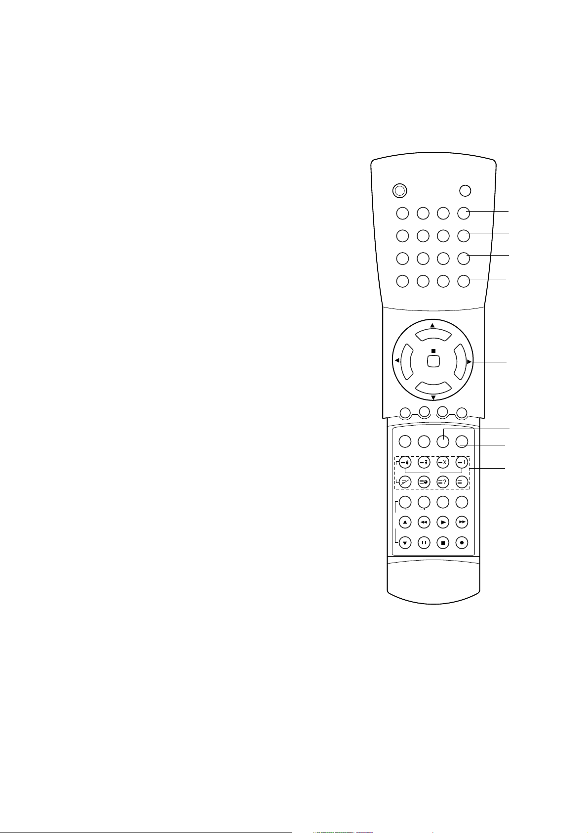
CONTROLS DESCRIPTION
All the functions can be controlled with the remote control handset.
Some functions can also be adjusted with the buttons on the front
panel of the set.
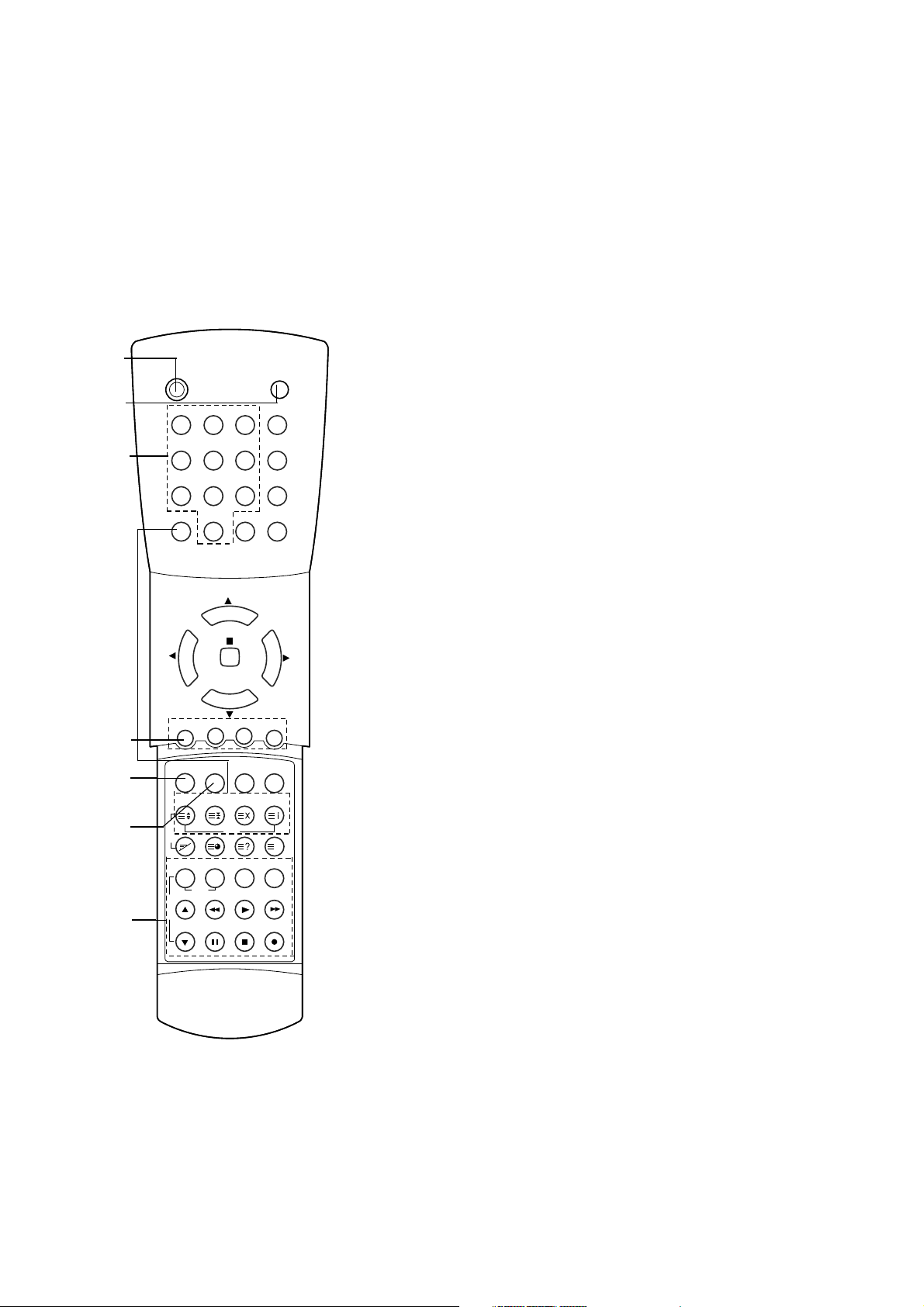
Remote control handset
Before you use the remote control handset, please install the
batteries. See the next page.
1. POWER
switches the set on from standby or off to standby.
2. MUTE
switches the sound on or off.
3. NUMBER BUTTONS
switch the set on from standby or directly select a number.
4. PIP BUTTONS (option)
PIP
switches the sub picture on or off.
PR+/-
selects a programme for the sub picture.
SWAP
alternates between main and sub picture.
INPUT
selects the input mode for the sub picture.
SIZE
adjusts the sub picture size.
STILL
freezes motion of the sub picture.
POSITION
relocates the sub picture in clockwise direction.
9/4 PIP
switches on or off the programme scan mode through 9 or 4
sub pictures.
5. PSM (Picture Status Memory)
recalls your preferred picture setting.
6. SSM (Sound Status Memory)
recalls your preferred sound setting.
7. VCR BUTTONS (option)
control a LG video cassette recorder.
POWER
MUTE
1 2 3 I/II
4 5 6 PSM
7 8 9 TV/AV
PIP 0 TEXT MENU
PSM
PR- PR+ SWAP INPUT
SSM DUAL LIST
SIZE STILL
START
QSR
LENGTH SP/LP ON/OFF
CH+ REW PLAY FF
CH- P/STILL STOP REC
POSITION
PIP
9/4 PIP
PR
PR
OK
VOL
VOL
T
X
T
V
C
R
M
1
2
3
4
5
6
7
- 9 -
8. DUAL
selects the language during dual language broadcast.
selects mono sound during stereo broadcasts.
9. TV/AV
selects TV or AV mode.
10. MENU
selects a menu.
11. ¡ª/¡ (Programme Up/Down)
switches the set on from standby.
selects a programme or a menu item.
¢‚/¢” (Volume Down/Up)
adjusts the volume.
adjusts menu settings.
OK
accepts your selection or displays the current mode.
12. LIST
display the programme table.
13. TELETEXT BUTTONS (option)
These buttons are used for teletext.
For further details, see the 'Teletext' section.
Note : In teletext mode, the PR+/-, SWAP and INPUT buttons are
used for teletext function.
POWER
MUTE
1 2 3 I/II
4 5 6 PSM
7 8 9 TV/AV
PIP 0 TEXT MENU
PSM
PR- PR+ SWAP INPUT
SSM DUAL LIST
SIZE STILL
START
QSR
LENGTH SP/LP ON/OFF
CH+ REW PLAY FF
CH- P/STILL STOP REC
POSITION
PIP
9/4 PIP
PR
PR
OK
VOL
VOL
T
X
T
V
C
R
M
8
5
9
10
8
12
13
11

- 10 -
1. MAIN POWER (on the side of TV)
switches the set on or off.
2. AUDIO/VIDEO(or S-VIDEO) IN SOCKETS
(AV 2)
Connect the audio/video(or S-video) out
sockets of external equipment to these
sockets.
3. TV/AV
selects TV or AV mode.
4. MENU
selects a menu.
5. OK
accepts your selection or displays the current
mode.
6. ¢‚/¢” (Volume Down/Up)
adjusts the volume.
adjusts menu settings.
7. ¡ª/¡ (Programme Up/Down)
switches the set on from standby.
selects a programme or a menu item.
8. POWER
switches the set on from standby or off to
standby.
9. POWER / STANDBY INDICATOR
illuminates when the set is in standby mode.
dims when the set is switched on.
10. REMOTE CONTROL SENSOR
S-VIDEO
TV/AV
MENU
OK VOL PR
VIDEO
L/MONO
AUDIO R
AV 2
6
9
5 8
10
7
4
3
1
2
Front panel
* CASTERS (on the bottom)
turn and move the set easily.
- 11 -
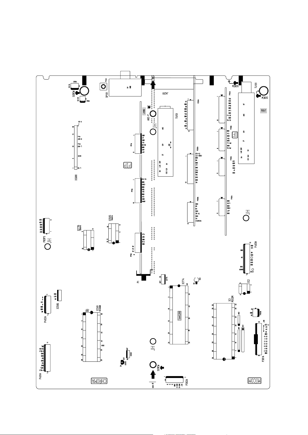
ALIGNMENT/TEST POINT LOCATION GUIDE
SIGNAL Board (Component side)
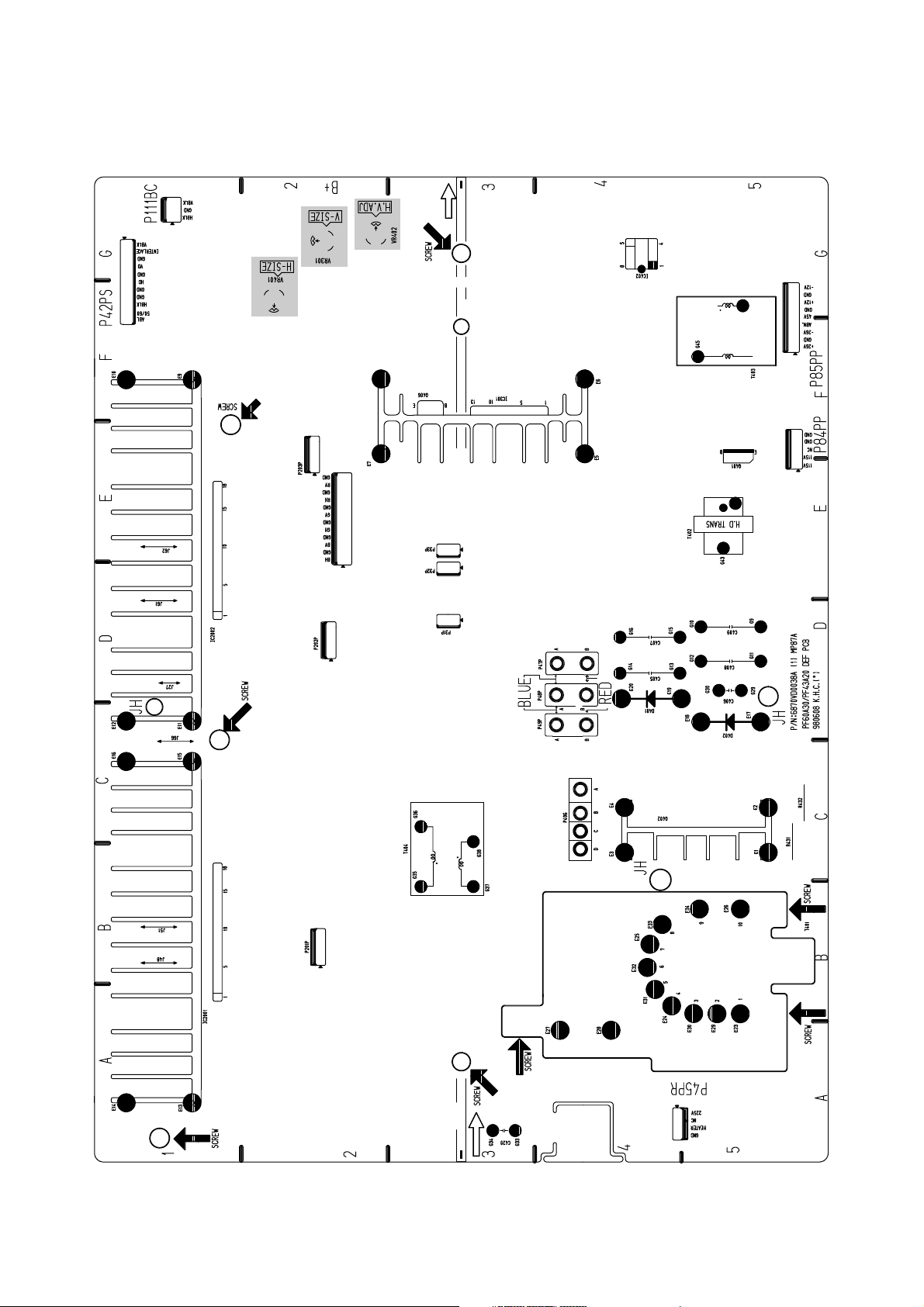
DEFLECTION Board (Component side)
- 12 -
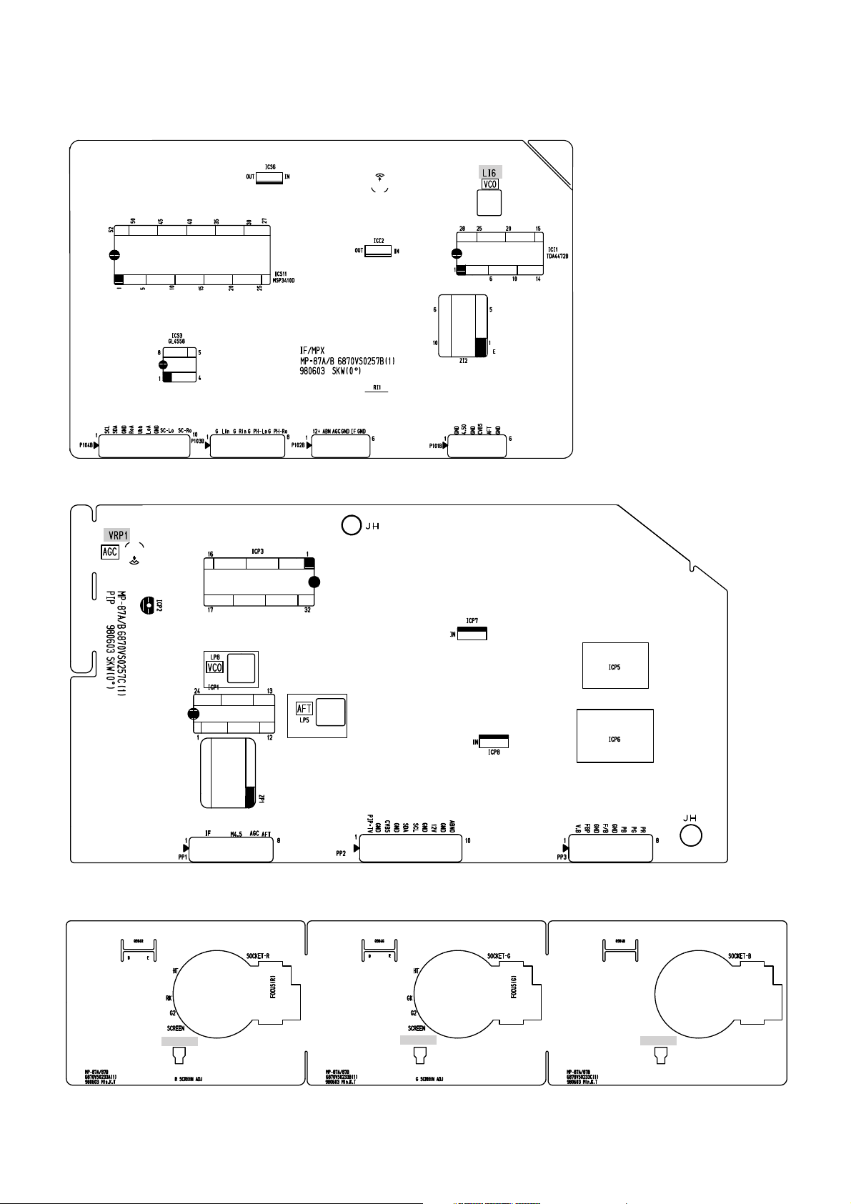
IF (Component side)
- 13 -
PIP (Component side)
CPT Board (Component side)
VR902R
VR902G
VR902B
§ Safety Precautions
1. It is safe to adjust after using insulating transformer
between the power supply line and chassis input to prevent
the risk of electric shock and protect the instrument.
2. Never disconnect leads while the TV receiver is on.
3. Don't short any portion of circuits while power is on.
4. Don't operate the TV with a non-moving picture for any
more than 10 minutes as damage may occur to the phosphor
on the CRT.
5. The adjustment must be done by the appropriate appliances
and the correct step.
6. Unless otherwise noted, set the line voltage to 220V ¡ 10%,
50Hz.
§ Test Equipment required
1. VIF sweep generator
2. Color bar/cross-hatch pattern generator
3. DC power supply
4. Digital multi-meter
5. Color analyzer
NOTE :
: PIP Board
¡ Main VCO (Voltage Controlled Oscillator)
Adjustment
1) Turn on DC power supply.
2)
Adjust LI6 so that the waveform of Oscilloscope becomes
2.6V DC.
¡ PIP VCO (Voltage Controlled Oscillator)
Adjustment
1) Turn on DC power supply.
2)
Adjust Video Detector Coil ( LP8 ) so that a waveform on
Alignment Scope is the same as below Fig.2.
¡ AFT (Auto Fine Tuning) Adjustment
1) Turn on DC power supply.
2) Adjust IF AFT coil (LP5 ) so that 38.0MHz (Vc) point may
be centered as Fig.3.
Test Point : TP22
Adjust : LP8
ADJUSTMENT INSTRUCTIONS
Test Point : TP3
Adjust : LI6
- 14 -
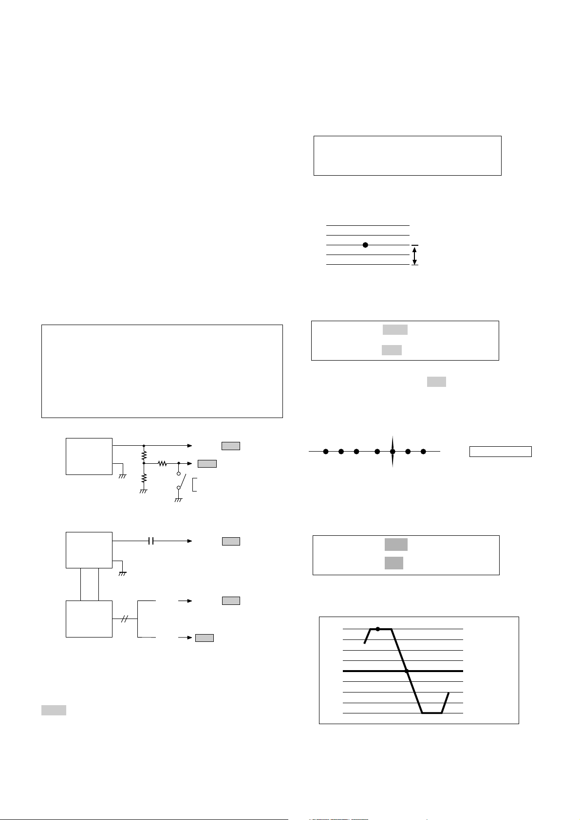
Preparation for VCO & AFT Adjustment
1. Connect the measuring equipment to the TV as shown in
Fig.1.
2. Set RF output level of Sweep S.G (Signal Generator) to
90dBuV.
3. Set Alignment Scope, Volts/Div to 100mV (VCO) or
1V(AFT), AC/DC switch to AC, Line/Ext switch to Ext.
Fig.1 : Connection Diagram of Equipment for
VCO & AFT Adjustment.
2.6V
GND
A B C D E F G
A : 30.0MHz
B : 31.5MHz
C : 32.84MHz
D : 36.8MHz
E : 38.0MHz
F : 39.5MHz
G : 40.25MHz
Fig.2 : VCO waveform on Alignment Scope
Test Point : TP23
Adjust : LP5
Fig.3: AFT waveform on Alignment Scope
DC POWER
SUPPLY
+
12 0.1V
-
3.3K
1K
4.7K
To TP2/ TP21
TP24
VCO : ON
AFT : OFF
SWEEP S.G.
with Marker
(VP-8800G)
Alignment
Scope
0.01µF
(VCO)
(AFT)
To TP1/ TP20
To TP3/ TP22
TP23
A
B
A: 36.8MHz
B: 38.0MHz
Test Point : J104/ J106
Adjust : VRI1 / VRP1
¡ RF AGC (Auto Gain Control) Adjustment
The RF AGC control (VRI1/ VRP1 ) was aligned at the time of
manufacture for optimum performance over a wide range
conditions. Readjust of VRI1/ VRP1 should not be necessary
unless unusual local conditions exist, such as:
1) Channel interference in a CATV system.
2) Picture bending and/or color beats, which are unusually
due to excessive RF signal input when the receiver is too
close to a transmitting tower or when the receiver is
connected to an antenna distribution system where the
RF signal has been amplified. In this case, the input signal
should be attenuated(with pad or filter) to a satisfactory
level.
3) Picture noise caused by "broadcast noise" or weak signal.
If the broadcast is "clean" and the RF signal is at least
1mV(60dBuV), the picture will be noise free in any area.
Adjusting the VRI1/ VRP1 (RF AGC) control to one end of
rotation will usually cause a relatively poor signal to noise
ratio;
Adjusting to the other end of rotation will usually cause a
degradation of over load capabilities resulting in color beats
or adjacent channel reference.
For best results, adjust the VRI1/ VRP1 control while
performing on all over local channels, or the voltage at J150/
J151 will be 6.0¡ 0.1Vdc in RF level 60¡ 1dBuV.
¡ High Voltage Stabilization Adjustment
1) Tune the TV set to receive a digital pattern.
2) Set contrast to 100%, brightness and color to 50%
respectively.
3) Adjust VR402 on the deflection board so that the DC
voltmeter may be read 4.0¡ 0.1Vdc.
¡ Vertical/Horizontal Size Adjustment
1) Tune the TV set to receive a digital pattern.
2) Set contrast to 100%, brightness and color to 50%
respectively.
3) Adjust VR301 on the deflection board so that the circle of
the digital pattern may be located within the effective
screen on the TV screen.
4) Adjust VR401 on the deflection board so that the circle of
the digital pattern looks like exact circle.
¡ Cut-off Adjustment
NOTE : This adjustment should be performed after
warming up for 15 minutes at least.
1) Set VR902R, 902G, 902B on CRT Boards to the
mechanical center position.
2) Tune the TV set to receive white pattern of PAL
standard signal.
3) Press OK button on Control Board continuously and
INPUT(blue) button on remote controller for obtaining a
horizontal line on the middle of TV screen.
4) Turn VR902R, 902G, 902B counterclockwise and set it to
the minimum position.
5) Turn VR902R, 902G, 902B clockwise slowly to appear a
horizontal line.
- 15 -
Test Point : J67 (on Deflection Board)
Adjust : VR402
Test Point : Observing Display
Adjust : VR301 (Vertical Size)
VR401 (Horizontal Size)
Test Point : Observing Display
Adjust : VR902R, 902G, 902B (Cut-off)
- 16 -
Caution :
These adjustments have been factory aligned. Do not attempt
to temper with these alignments. However, the effects of
adjacent receiver components, or replacement of picture tube
or deflection yoke may require the need to readjust these
adjustments.
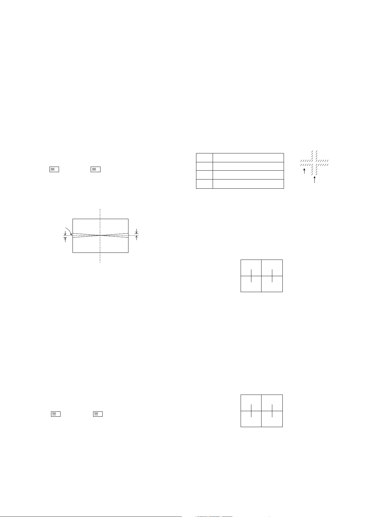
¡ Raster Slant Adjustment
1. Peliminary steps
1) The lens focus and electrical focus must be provisional
alignment.
2) Tune the TV set to receive a digital pattern.
3)
Press the buttons of Remote Controller for adjustment (SVC
¡ ¡ 5¡ OK¡ ) to reset the convergence.
2. Adjustment
1) Set only green to be appeared on the screen.
2) Carefully rotate the DY of the green CRT so that the slant
of raster become the following figure.
3) Set two color (R or B and G) to be appeared on the
screen.
4) Set the slant of Red or Blue correspond to the green.
Note :
¡ Raster Position Adjustment
1. Preliminary steps
1) The lens focus and electrical focus must be provisional
alignment.
2) This adjustment should be performed after the raster
slant, the horizontal and the vertical adjustment.
3) Tune the TV set to receive a digital pattern.
4) The convergence must be corrected.
Press the buttons of Remote Controller for adjustment (SVC
¡ ¡ 5¡ OK¡ ) to reset the convergence.
2. Adjustment
1) Turn the centering magnet of Green CRT so that the center
of video signal correspond to geometrical center of screen.
2) Tune the TV set to receive cross hatch signal and turn the
centering magnet of Red & Blue so that the center of
cross hatch pattern correspond to Green center.
¡
Lens and Electrical Focus Adjustment
1. Preliminary steps
1) The electrical focus, the raster slant and position must be
provisional alignment.
2) This adjustment should be performed after warming up
for 30 minutes and in the dark room.
3) Tune the TV set cross hatch pattern.
4) Screen the optional two lens with a cover so that the
single color is appeared on the screen.
5) When turn the light the lens at front, chromatic aberration
which appeared in bright line of cross-Hatch signal
changed as below.
¡ After focus adjustment, fix screw about 12~ 17kg.cm.
2. G-lens Adjustment
1) Turn the lens until the chromatic aberration changed 'Blue'
to 'Red point'.
2)
Viewing the all screen, in no case of the chromatic aberration
appeared slimly within 3.5 cross-Hatch of the picture center.
At this time, in case that the red chromatic aberration's bright
line isn't equal, adjust G-lens so that the red chromatic
aberration is appeared more than previous time.
3) Switching the signal to digital pattern and operate
adjustment minutely. At this time, adjust it by using the
revolution pattern of circumferencial picture's small circle.
4) Adjust G-focus control volume of focus pack so that the
external big circle's part appeared cleary.
5) Adjust accurately by repeat the upper control.
6) Especially, noting to the G-light because it influenced on
picture's function.
3. R-lens Adjustment
1) Turn the lens until the chromatic aberration changed
orange to scarlet.
2) Adjust the chromatic aberration so that it located center
correctly.
3) Switching the signal to digital pattern and adjust it as
same method of G-lens.
4) Adjust as same method of G-lens with Red focus control
volume of focus pack.
RASTER SLANT/POSITION, FOCUS & CONVERGENCE ADJUSTMENT
L
L
Mechanical
center
1. Tighten the tighten iron after loose completely
tighten iron which fixing DY when adjusting raster
slant and set position.
2. Never control to the tighten iron which fixed, it's
condition is not untied.
Lens
Red
Green
Blue
Change of chromatic aberration
Orange ¤AScarlet
Blue ¤ARed
Purple ¤AGreen
CHROMATIC
ABERRATION
CROSS HATCH
SIGNAL
L ¡´ 2mm
M
M
M
M

- 17 -
4. Blue lens Adjustment
1) Turn the lens until the chromatic aberration changed
purple to green which of 3.5 Cross-Hatch part from
picture's center toward left.
2) Adjust the chromatic aberration become center of purple
and green.
3) Turn the VR to clockwise so that the thickness of Bbright line thicker than G-bright line as much as times of
1.3 ¡ 0.2 after control method as same of G-focus by Bfocus VR of focus pack.
4) Remove lens cover after adjusting all lens (R.G.B) and
receive cross hatch signal, observing condition of whole
screen's condition.
¡ Convergence Adjustment
1. Preliminary steps
1) This adjustment should be performed after raster slant,
raster position, horizontal and vertical adjustment.
2) This adjustment should be performed after warming up
30 minutes.
3) Tune the TV set cross-hatch pattern.
4) Adjust for both PAL(SECAM) and NTSC system.
5) Use the jig screen with the cross hatch pattern for each
mode.
2. Convergence Key(Button)
1) Convergence Mode :
2) Phase Adjustment : 95
3) Pattern Position Adjustment : 94
4) Phase/Pattern Position Save : 92
5) Cursor Color Selection : TV/AV
6) Cursor Movement/Adjustment Selection : OK
7) Adjustment DATA Save : 91
¡ Mode Adjustment
1. Preliminary steps
Press the buttons SVC & of Remote Controller for
adjustment to get into the convergence adjustment mode.
2. Phase Adjustment
1) Press the buttons 9 & 5 to get into the phase adjustment
mode.
2) Horizontal Phase Adjustment.
Press the volume ¢‚/¢”button and move the convex part
to the middle of TV screen.
3) Vertical Phase Adjustment
Press the channel ¡ª/¡ button and move the convex part
to the middle of TV screen.
Press the OK button to escape from the adjustment.
3. Pattern Position Adjustment
Press the buttons 9 & 4 to get into the pattern movement
mode.
Press the volume ¢‚/¢”button & channel ¡ª/¡ button and
move the cursor to the middle of TV screen.
4. Phase/Pattern Position Save
Press buttons 9 & 2 and OK.
5. Green Convergence Adjustment
1) Press TV/AV button and select the green cursor.
2) Press the volume ¢‚/¢”button & channel ¡ª/¡ button and
adjust the green pattern & screen jig pattern.
3) If necessary, cover the R lens & B lens.
¡ Cursor flickers in the adjustment mode and stops in the
cursor position movement mode.
Use OK button to toggle the cursor position movement
mode and adjustment mode.
Adjust and move outskirts from center.
Number is the order for adjustment position.
Adjust anyone first for the same number.
M
M
The second mark
The horizontal center-line
The horizontal center
The vertical
center
The horizontal center
The vertical
center
8 6 5 4 5 6 8
7 5 3 2 3 5 7
6 4 2 1 2 4 6
7 5 3 2 3 5 7
8 6 5 4 5 6 8

6. Red Convergence Adjustment
1) Press TV/AV button and select the red cursor.
2) If necessary, cover B lens.
3) Adjust as same as the green convergence adjustment and
coincide the red pattern with the green pattern.
7. Blue Convergence Adjustment
1) Press TV/AV button and select the blue cursor.
2) Adjust as same as the red convergence adjustment and
coincide the blue pattern with the green pattern.
8. Adjustment DATA Save
Press buttons 9 & 1 and save adjustment DATA.
9. Press button to escape from the adjustment.
¡ White Balance Adjustment
1. Used Tools : Brightness meter (TOPCON BM-7)
2. Condition
1) It must be operated at a place of the darkroom.
2) This adjustment must be performed after focus
adjustment finished.
3) Brightness meter must be at a place of 3[m] from the
middle of optical screen.
4) Adjust focus of brightness meter to optical screen.
And adjust the field angle. (1¡£)
3. Adjustment
1) Receive the white balance signal of 100%.
2) Select SVC Mode by SVC Remote Controller.
3) Adjust G-GN & B-GN and X=0.280 & Y=0.300. (Deviation :
¡ 0.005)
¡ Sub White Balance Adjustment
1) Press OK buttons on both of TV and Remote Controller at
the same time to get into SVC mode.
2) Press the Yellow button to find a TABLE of below 3
tables.
3) Select a menu with channel up/down button and adjust
the data with volume ¡ª/¡ button.
4) Press OK button to save the data.
5) Press TV/AV button to escape the SVC mode.
- 18 -
M
SVC 3 MODE
SVC 3 MODE
SVC 3 MODE
FM PRE
NC PRE
SC PRE
SC VOL
PH VOL
H-CEN
SBRIGHT
STINT
Rcut
Gcut
Bcut
G-GN
B-GN
128
141
112
138
111
09
50
50
19
74
36
50
50
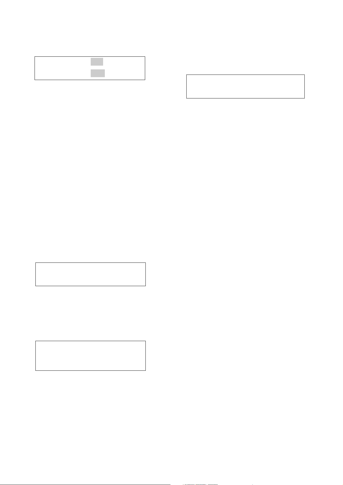
<Table 1> <Table 2> <Table 3>
 Loading...