

LG PRHR Series, multi V PRHR020, multi V PRHR040, multi V PRHR030, Multi V PRHR021 Installation Manual
...
System
Heat Recovery Unit
INSTALLATION MANUAL
LG
MODELS: PRHR Series
website http://www.lgservice.com
IMPORTANT
• Please read this installation manual completely before
installing the product.
• Installation work must be performed in accordance with
the national wiring standards by authorized personnel
only.
• Please retain this installation manual for future reference
after reading it thoroughly.
ENGLISH ITALIANO ESPAÑOL FRANÇAIS DEUTSCH
PORTUGUESE

2 HR Unit
PRHR Series Heat Recovery Unit Manual
TABLE OF CONTENTS
Safety Precautions....................3
Features & Installation Part......4
Installation
Selection the best location &
Dimensional Drawings.................5
HR Unit installation......................6
Thermal insulation & Wiring con-
nection.........................................8
Setup the switch of HR Unit ........9
Coil Exchanging method ........12
■ Pipes: Low Pressure Gas side
High Pressure Gas side
Liquid side
■ Suspension bolts, Flat wash-
ers
■ Insulation materials
■ Connecting cable
■ Electric drill
■ Hole core drill
■ Spanner .....half union
■ Brazing machine
■ Nitrogen gas
■ Gas-leak detector
■ Screw driver
Installation Requirements
Required Parts Required Tools
ENGLISH
Installation Manual 3
Safety Precautions
Safety Precautions
To prevent injury to the user or other people and property damage, the following instructions must be followed.
■ Incorrect operation due to ignoring instruction will cause harm or damage. The seriousness is classified by
the following indications.
This symbol indicates the possibility of death or serious injury.
This symbol indicates the possibility of injury or damage to properties only.
Have all electric work done by a licensed electrician according
to "Electric Facility Engineering Standard" and "Interior Wire
Regulations" and the instructions given in this manual and
always use a special circuit.
• If the power source capacity is inadequate or electric work is per-
formed improperly, electric shock or fire may result.
Ask the dealer or an authorized technician to install the HR
unit.
• Improper installation by the user may result in water leakage, electric shock, or fire.
Always ground the product.
• There is risk of fire or electric shock.
Make the connections securely so that the outside force of the
cable may not be applied to the terminals.
• Inadequate connection and fastening may generate heat and
cause a fire.
For re-installation of the installed product, always contact a
dealer or an Authorized Service Center.
• There is risk of fire, electric shock, explosion, or injury.
Do not install, remove, or re-install the unit by yourself (customer).
• There is risk of fire, electric shock, explosion, or injury.
Do not damage or use an unspecified power cord.
• There is risk of fire, electric shock, explosion, or injury.
Do not touch the power switch with wet hands.
• There is risk of fire, electric shock, explosion, or injury.
Avoid a place where rain may enter since the HR unit is
for indoor.
• There is risk of property damage, failure of product, or electric shock.
Install the HR unit at a place in which it is not affected
by operation mode changing noise.
• Installation within cell such as meeting room etc. may disturb business due to noise.
Always check for gas (refrigerant) leakage after installation or repair of product.
• Low refrigerant levels may cause failure of product.
Keep level even when installing the product.
•
To avoid vibration or water leakage.
Securely install the cover of control box and the panel.
• If the cover and panel are not installed securely, dust or water may
enter the HR unit and fire or electric shock may result.
Be cautious when unpacking and installing the product.
• Sharp edges could cause injury. Be especially careful of the case
edges.
Safely dispose of the packing materials.
• Packing materials, such as nails and other metal or wooden parts, may cause stabs or other injuries.
• Tear apart and throw away plastic packaging bags so that children may not play with them. If children play with a plastic bag which was
not torn apart, they face the risk of suffocation.
Do not store or use flammable gas or combustibles near the
HR Unit.
• There is risk of fire or failure of product.
Use the correctly rated breaker or fuse.
• There is risk of fire or electric shock.
4 HR Unit
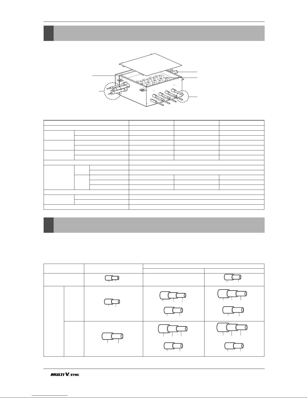
Features & Installation Part
Features
Installation Part
• Installation Manual
• Hanging bolts (4 x M10 or M8, Nut(8 x M10 or M8), Flat washers(8 x M10)
• Reducers
Control Box
Connection Pipe
(to outdoor unit)
Connection Pipe
(to outdoor unit)
Coil assembly, Solenoid
Connection Pipe
(to indoor unit)
Model
Max. Connectable No. of Indoor Units
Nominal Input
Cooling
Heating
Net. Weight
kg
lbs
Dimensions
Inch
(W*H*D)
mm
Casing
Connecting Pipes Indoor
Liquid Pipe [mm/inch]
Gas Pipe [mm/inch]
Outdoor Liquid [mm/inch
]
Low Pressure [mm/inch]
High Pressure [mm/inch]
Sound Absorbing Insulation Material
Current
Minimum circuit Amps(MCA)
Maximum fuse Amps(MFA)
Power Supply
PRHR020 PRHR030 PRHR040
243
26 40 40
26 40 40
19 20 21
41.9 44.1 46.3
31.5*8.6*24.3 31.5*8.6*24.3 31.5*8.6*24.3
801*218*617 801*218*617 801*218*617
Galvanized steel plate
Ø9.52[3/8
Ø15.88[5/8]
Ø9.52[3/8) Ø12.7[1/2] Ø12.7[1/2]
Ø22.2[7/8] Ø28.58[1
1
/8] Ø28.58[11/8]
Ø19.05[3/4] Ø22.2[7/8] Ø22.2[7/8]
Flame and resistant foamed polyetinylene
0.2
15
1, 50 Hz, 220~240V
Models
High pressure
Gas pipe
Low pressure
Liquid pipe
Indoor unit
reducer
HR unit
reducer
PRHR020
PRHR030/
PRHR040
OD22.2 Ø19.05 Ø15.88
OD15.88
Ø12.7
Ø6.35
OD9.52
Ø6.35OD9.52
OD19.05
Ø15.88 Ø12.7
OD12.7 Ø9.52
OD12.7 Ø9.52
OD15.88 Ø12.7
OD22.2 Ø19.05 Ø15.88
OD28.58 Ø22.2 Ø19.05
OD15.88 Ø12.7
OD19.05 Ø15.88
 Loading...