

LG multi V PLUS Service Manual
System
Air Conditioner
SERVICE MANUAL
LG
MODELS: LRUV/LRUN Series
LRNV/LRNN Series
website http://www.lgservice.com
CAUTION
• BEFORE SERVICING THE UNIT, READ THE SAFETY
PRECAUTIONS IN THIS MANUAL.
• ONLY FOR AUTHORIZED SERVICE PERSONNEL.

2
Air Conditioner Service Manual
TABLE OF CONTENTS
Safety Precautions .......................................................................................3
Model Names...............................................................................................11
External Appearance..................................................................................12
Combination of Outdoor Units ..................................................................14
Nomenclature..............................................................................................15
Outdoor Units Information.........................................................................16
Indoor Units
...........................................................................................21
Ceiling Mounted Cassette Type (1Way)................................................22
Ceiling Mounted Cassette Type (4 way)................................................33
Ceiling Concealed Duct Type (High static)...........................................56
Ceiling Concealed Duct Type (Low static)............................................75
Convertible Type.....................................................................................87
Wall Mounted Type................................................................................107
Art Cool Type(Deluxe) ..........................................................................123
Art Cool Type.........................................................................................143
Art Cool Type(Wide)..............................................................................161
Outdoor Units.....................................................................................179
LRUV/LRUN Series................................................................................180
Trouble Shooting Guide .......................................................................245
Appendix................................................................................................297
Exploded View & Replacement Parts List..........................................303
Safety Precautions
Service Manual 3
Safety Precautions
To prevent injury to the user or other people and property damage, the following instructions must
be followed.
■ Incorrect operation due to ignoring instruction will cause harm or damage. The seriousness is
classified by the following indications.
■ Meanings of symbols used in this manual are as shown below.
This symbol indicates the possibility of death or serious injury.
This symbol indicates the possibility of injury or damage to properties only.
Be sure not to do.
Be sure to follow the instruction.
■ Installation
Have all electric work done by a licensed
electrician according to "Electric Facility
Engineering Standard" and "Interior Wire
Regulations" and the instructions given in
this manual and always use a special circuit.
• If the power source capacity is inadequate or
electric work is performed improperly, electric
shock or fire may result.
Ask the dealer or an authorized technician to
install the air conditioner.
• Improper installation by the user may result in
water leakage, electric shock, or fire.
Always ground the product.
• There is risk of fire or electric shock.
Always intstall a dedicated circuit and breaker.
• Improper wiring or installation may cause fire or
electric shock.
4
Safety Precautions
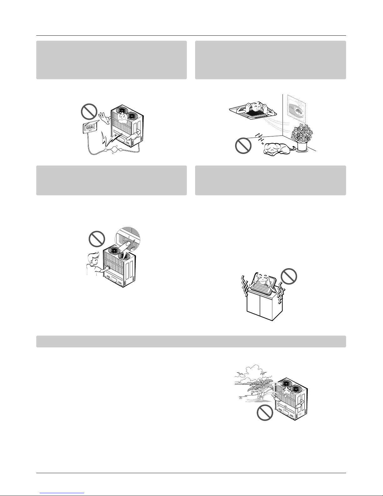
For re-installation of the installed product,
always contact a dealer or an Authorized
Service Center.
• There is risk of fire, electric shock, explosion, or
injury.
Do not install, remove, or re-install the unit
by yourself (customer).
• There is risk of fire, electric shock, explosion, or
injury.
Do not store or use flammable gas or
combustibles near the air conditioner.
• There is risk of fire or failure of product.
Use the correctly rated breaker or fuse.
• There is risk of fire or electric shock.
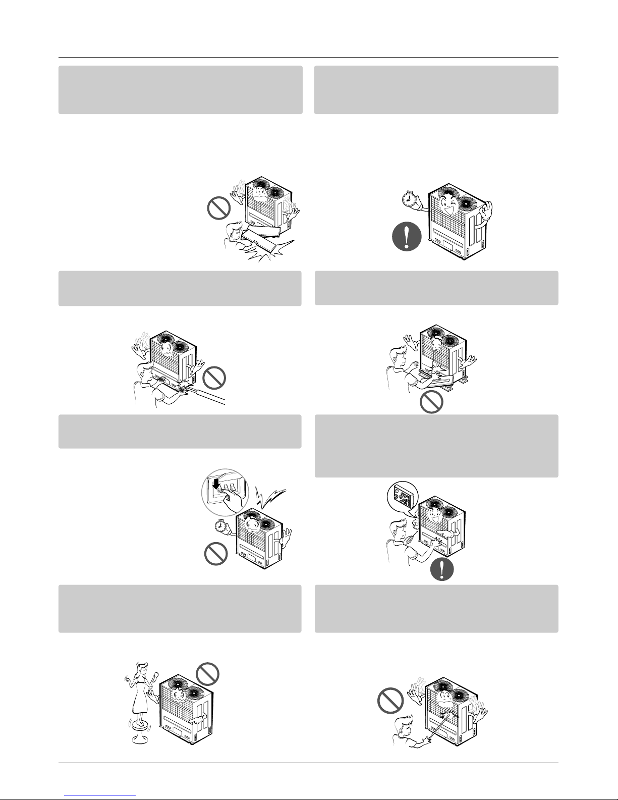
Prepare for strong wind or earthquake and
install the unit at the specified place.
• Improper installation may cause the unit to topple and result in injury.
Do not install the product on a defective
installation stand.
• It may cause injury, accident, or damage to the
product.
When installing and moving the air conditioner to another site, do not charge it with a
different refrigerant from the refrigerant
specified on the unit.
• If a different refrigerant or air is mixed with the
original refrigerant, the refrigerant cycle may
malfunction and the unit may be damaged.
Do not reconstruct to change the settings of
the protection devices.
• If the pressure switch, thermal switch, or other
protection device is shorted and operated
forcibly, or parts other than
those specified by LGE are
used, fire or explosion may
result.
Gasolin

Safety Precautions
Service Manual 5
Ventilate before operating air conditioner
when gas leaked out.
• It may cause explosion, fire, and burn.
Securely install the cover of control box and
the panel.
• If the cover and panel are not installed securely,
dust or water may enter the outdoor unit and fire
or electric shock may result.
If the air conditioner is installed in a small room, measures must be taken to prevent the
refrigerant concentration from exceeding the safety limit when the refrigerant leaks.
• Consult the dealer regarding the appropriate measures to prevent the safety limit from being exceeded. Should the refrigerant leak and cause the safety limit to be exceeded, harzards due to lack of oxygen in the room could result.
■ Operation
Do not damage or use an unspecified power
cord.
• There is risk of fire, electric shock, explosion, or
injury.
Use a dedicated outlet for this appliance.
• There is risk of fire or electrical shock.
Be cautious that water could not enter the
product.
• There is risk of fire, electric shock, or product
damage.
Do not touch the power switch with wet
hands.
• There is risk of fire, electric shock, explosion, or
injury.
6
Safety Precautions
When the product is soaked (flooded or
submerged), contact an Authorized Service
Center.
• There is risk of fire or electric shock.
Be cautious not to touch the sharp edges
when installing.
• It may cause injury.
Take care to ensure that nobody could step
on or fall onto the outdoor unit.
• This could result in personal injury and product
damage.
Do not open the inlet grill of the product during operation. (Do not touch the electrostatic
filter, if the unit is so equipped.)
• There is risk of physical injury, electric shock, or
product failure.
■ Installation
Always check for gas (refrigerant) leakage
after installation or repair of product.
• Low refrigerant levels may cause failure of
product.
Do not install the product where the noise or
hot air from the outdoor unit could damage
the neighborhoods.
• It may cause a problem for your neighbors.
Keep level even when installing the product.
• To avoid vibration or water leakage.
Do not install the unit where combustible gas
may leak.
• If the gas leaks and accumulates around the
unit, an explosion may result.
90˚
Gasolin
Service Manual 7
Safety Precautions
Use power cables of sufficient current
carrying capacity and rating.
• Cables that are too small may leak, generate
heat, and cause a fire.
Do not use the product for special purposes,
such as preserving foods, works of art, etc. It
is a consumer air conditioner, not a precision
refrigeration system.
• There is risk of damage or loss of property.
Keep the unit away from children. The heat
exchanger is very sharp.
• It can cause the injury, such as cutting the finger.
Also the damaged fin may result in degradation
of capacity.
When installting the unit in a hospital, communication station, or similar place, provide
sufficient protection against noise.
•
The inverter equipment, private power generator,
high-frequency medical equipment, or radio communication equipment may cause the air conditioner to operate erroneously, or fail to operate. On the
other hand, the air conditioner may affect such
equipment by creating noise that disturbs medical
treatment or image broadcasting.
Do not install the product where it is exposed to sea wind (salt spray) directly.
• It may cause corrosion on the product. Corrosion, particularly on the condenser and evaporator fins,
could cause product malfunction or inefficient operation.

8
Safety Precautions
■ Operation
Do not use the air conditioner in special
environments.
• Oil, steam, sulfuric smoke, etc. can significantly
reduce the performance of the air conditioner or
damage its parts.
Do not block the inlet or outlet.
• It may cause failure of appliance or accident.
Make the connections securely so that the
outside force of the cablemay not be applied
to the terminals.
• Inadequate connection and fastening may generate heat and cause a fire.
Be sure the installation area does not deteriorate with age.
• If the base collapses, the air conditioner could
fall with it, causing property damage, product
failure, or personal injury.
Install and insulate the drain hose to ensure that water is drained away properly based on the
installation manual.
• A bad connection may cause water leakage.
Be very careful about product transportation.
• Only one person should not carry the product if it weighs more
than 20 kg.
• Some products use PP bands for packaging. Do not use any PP
bands for a means of transportation. It is dangerous.
• Do not touch the heat exchanger fins. Doing so may cut your fingers.
• When transporting the Outdoor Unit, suspending it at the specified
positions on the unit base. Also support the Outdoor Unit at four
points so that it cannot slip sideways.
Service Manual 9
Safety Precautions
Safely dispose of the packing materials.
•
Packing materials, such as nails and other metal or
wooden parts, may cause stabs or other injuries.
•
Tear apart and throw away plastic packaging bags
so that children may not play with them. If children
play with a plastic bag which was
not torn apart, they face the
risk of suffocation.
Turn on the power at least 12 hours before
starting operation.(In case of outdoor
temperature 5°C below)
• Starting operation immediately after turning on
the main power switch can result in severe
damage to internal parts. Keep the power switch
turned on during the operational season.
Do not touch any of the refrigerant piping
during and after operation.
• It can cause a burn or frostbite.
Do not operate the air conditioner with the
panels or guards removed.
• Rotating, hot, or high-voltage parts can cause
injuries.
Do not directly turn off the main power
switch after stopping operation.
• Wait at least 5 minutes before turning off the
main power switch.
Otherwise it may result in
water leakage or other
problems.
Auto-addressing should be done in condition of
connecting the power of all indoor and outdoour
units. Auto-addressing should also be done in
case of changing the Indoor Unit board(PCB).
Use a firm stool or ladder when cleaning or
maintaining the air conditioner.
• Be careful and avoid personal injury.
Do not insert hands or other objects through
the air inlet or outlet while the air conditioner
is plugged in.
• There are sharp and moving parts that could
cause personal injury.
10
Part 1
General Information
1. Model Names ................................................................11
1.1 Indoor Unit.............................................................11
1.2 Outdoor Unit..........................................................11
2. External Appearance.....................................................12
2.1 Indoor Unit.............................................................12
2.2 Outdoor Unit..........................................................13
3. Combination of Outdoor Units.....................................14
4. Nomenclature.................................................................15
4.1 Indoor Unit..............................................................15
4.2 Outdoor Unit...........................................................15
5. Outdoor Units Information............................................16
Service Manual 11
1. Model Names
1.1 Indoor Unit
1.2 Outdoor Unit
Model Names
Wall Mounted
SR
(General)
ST
Deluxe SU
ART COOL ART COOL SP
ART COOL Wide
SV
1 Way TC
4 Way
TE
TD
BH
High Static BG
BE
Low Static BT
Ceiling & Floor Convertible VB
Capacity(Btu/h(kW))
Category
Chassis
Name
7k 9k 12k 18k 21K 24k 28k 36k 38k 42k 4 8 k
(2.1) (2.6) (3.5) (5.3) (6.2) (7.0) (8.2) (10.6) (11.1) (12.3) (14.1)
076SRA0 096SRA0 126SRA0
072SRA0 092SRA0 122SRA0
186STA0
182STA0
076SU*0 096SU*0 126SU*0 186S3*0 246S3*0
072SU*0 092SU*0 122SU*0 122S3*0 242S3*0
096SP*0 126SP*0
092SP*0 122SP*0
126SV*0 186SV*0
122SV*0 182SV*0
076TCA0 096TCA0 126TCA0
072TCA0 092TCA0 122TCA0
126TEA0 186TEA0
122TEA0 182TEA0
216TDA0 246TDA0 286TDA0 366TDA0 386TDA0 426TDA0 486TDA
212TDA0 242TDA0 282TDA0 362TDA0 382TDA0 422TDA0 482TDA0
186BHA0 216BHA0 246BHA0
182BHA0 212BHA0 242BHA0
286BGA0 366BGA0 386BGA0 426BGA0
282BGA0 362BGA0 382BGA0 422BGA0
486BEA0
482BEA0
076BTG0 096BTG0 126BTG0
072BTG0 092BTG0 122BTG0
186VBA0 246VBA0
182VBA0 242VBA0
Ceiling
Concealed
Duct
Ceiling
Cassette
Cooling Only LRNV
Heat Pump LRNN
1Ø, 220 ~ 240V, 50Hz 6
1Ø, 220V, 60Hz 2
Cooling Only LRUV
Heat Pump LRUN
Power Supply 5HP 6HP 8HP 10HP 12HP 14HP 16HP 18HP 20HP 22HP
3Ø, 380 ~ 415V, 50Hz 508T0 608T0 808T0 1008T0 1208T0 1408T0 1608TS0 1808TS0 2008TS0 2208TS0
3Ø, 380V, 60Hz 509T0 609T0 809T0 1009T0 1209T0 1409T0 1609TS0 1809TS0 2009TS0 2209TS0
3Ø, 220V, 60Hz 80BT0 100BT0 120BT0
Power Supply 24HP 26HP 28HP 30HP 32HP 34HP 36HP 38HP 40HP
3Ø, 380 ~ 415V, 50Hz 2408TS0 2608TR0 2808TR0 3008TR0 3208TR0 3408TR0 3608TR0 3808TR0 4008TR0
3Ø, 380V, 60Hz 2409TS0 2609TS0 2809TR0 3009TR0 3209TR0 3409TR0 3609TR0 3809TR0 4009TR0
These are model names of the basic function

12
2. External Appearance
2.1 Indoor Unit
Wall Mounted
ART COOL ART COOL Wide
ART COOL Deluxe
Ceiling Cassette- 1Way Ceiling Cassette- 4Way
Ceiling Concealed Duct - Low Static
Ceiling Concealed Duct - High Static
Ceiling & Floor - Convertible
LRNV076TCA0 / LRNN076TCA0 / LRNV072TCA0 / LRNN072TCA0
LRNV096TCA0 / LRNN096TCA0 / LRNV092TCA0 / LRNN092TCA0
LRNV126TCA0 / LRNN126TCA0 / LRNV122TCA0 / LRNN122TCA0
LRNV126TEA0 / LRNN126TEA0 / LRNV122TEA0 / LRNN122TEA0
LRNV186TEA0 / LRNN186TEA0 / LRNV182TEA0 / LRNN182TEA0
LRNV216TDA0 / LRNN216TDA0 / LRNV212TDA0 / LRNN212TDA0
LRNV246TDA0 / LRNN246TDA0 / LRNV242TDA0 / LRNN242TDA0
LRNV286TDA0 / LRNN286TDA0 / LRNV282TDA0 / LRNN282TDA0
LRNV366TDA0 / LRNN366TDA0 / LRNV362TDA0 / LRNN362TDA0
LRNV386TDA0 / LRNN386TDA0 / LRNV382TDA0 / LRNN382TDA0
LRNV426TDA0 / LRNN426TDA0 / LRNV422TDA0 / LRNN422TDA0
LRNV486TDA0 / LRNN486TDA0 / LRNV482TDA0 / LRNN482TDA0
LRNV186BHA0 / LRNN186BHA0 / LRNV182BHA0 / LRNN182BHA0
LRNV216BHA0 / LRNN216BHA0 / LRNV212BHA0 / LRNN212BHA0
LRNV246BHA0 / LRNN246BHA0 / LRNV242BHA0 / LRNN242BHA0
LRNV286BGA0 / LRNN286BGA0 / LRNV282BGA0 / LRNN282BGA0
LRNV366BGA0 / LRNN366BGA0 / LRNV362BGA0 / LRNN362BGA0
LRNV386BGA0 / LRNN386BGA0 / LRNV382BGA0 / LRNN382BGA0
LRNV426BGA0 / LRNN426BGA0 / LRNV422BGA0 / LRNN422BGA0
LRNV486BEA0 / LRNN486BEA0 / LRNV482BEA0 / LRNN482BEA0
LRNV076BTG0 / LRNN076BTG0 / LRNV072BTG0 / LRNN072BTG0
LRNV096BTG0 / LRNN096BTG0 / LRNV092BTG0 / LRNN092BTG0
LRNV126BTG0 / LRNN126BTG0 / LRNV122BTG0 / LRNN122BTG0
LRNV076SRA0 / LRNN076SRA0 / LRNV072SRA0 / LRNN072SRA0
LRNV096SRA0 / LRNN096SRA0 / LRNV092SRA0 / LRNN092SRA0
LRNV126SRA0 / LRNN126SRA0 / LRNV122SRA0 / LRNN122SRA0
LRNV186STA0 / LRNN186STA0 / LRNV182STA0 / LRNN182STA0
LRNV076SU*0 / LRNN076SU*0 / LRNV072SU*0 / LRNN072SU*0
LRNV096SU*0 / LRNN096SU*0 / LRNV092SU*0 / LRNN092SU*0
LRNV126SU*0 / LRNN126SU*0 / LRNV122SU*0 / LRNN122SU*0
LRNV186S3*0 / LRNN186S3*0 / LRNV182S3*0 / LRNN182S3*0
LRNV246S3*0 / LRNN246S3*0 / LRNV24S3*0 / LRNN242S3*0
LRNV096SP*0 / LRNN096SP*0 / LRNV092SP*0 / LRNN092SP*0
LRNV126SP*0 / LRNN126SP*0 / LRNV122SP*0 / LRNN122SP*0
LRNV126SV*0 / LRNN126SV*0 / LRNV122SV*0 / LRNN122SV*0
LRNV186SV*0 / LRNN186SV*0 / LRNV182SV*0 / LRNN182SV*0
LRNV186VBA0 / LRNN186VBA0 / LRNV182VBA0 / LRNN182VBA0
LRNV246VBA0 / LRNN246VBA0 / LRNV242VBA0 / LRNN242VBA0
* B : Blue M : Metal
D : Wood R : Mirror
C : Cherry W : White
* B : Blue M : Metal D : Wood * B : Blue M : Metal D : Wood
External Appearance
These are model names of the basic function.

Service Manual 13
LRUV508T0 / LRUN508T0 / LRUV509T0 / LRUN509T0
LRUV608T0 / LRUN608T0 / LRUV609T0 / LRUN609T0
LRUV808T0 / LRUV809T0
LRUN808T0 / LRUN809T0 / LRUV80BT0 / LRUN80BT0
LRUV1008T0 / LRUN1008T0 / LRUV1009T0 / LRUN1009T0 / LRUV100BT0 / LRUN100BT0
LRUV1208T0 / LRUN1208T0 / LRUV1209T0 / LRUN1209T0 / LRUV120BT0 / LRUN120BT0
LRUV1408T0 / LRUN1408T0 / LRUV1409T0 / LRUN1409T0
LRUV1608TS0 / LRUN1608TS0 / LRUV1609TS0 / LRUN1609TS0
LRUV1808TS0 / LRUN1808TS0 / LRUV1809TS0 / LRUN1809TS0
LRUV2008TS0 / LRUN2008TS0 / LRUV2009TS0 / LRUN2009TS0
LRUV2208TS0 / LRUN2208TS0 / LRUV2209TS0 / LRUN2209TS0
LRUV2408TS0 / LRUN2408TS0 / LRUV2409TS0 / LRUN2409TS0
LRUV2609TS0 / LRUN2609TS0
LRUV2608TR0 / LRUN2608TR0
LRUV2808TR0 / LRUN2808TR0 / LRUV2809TR0 / LRUN2809TR0
LRUV3008TR0 / LRUN3008TR0 / LRUV3009TR0 / LRUN3009TR0
LRUV3208TR0 / LRUN3208TR0 / LRUV3209TR0 / LRUN3209TR0
LRUV3408TR0 / LRUN3408TR0 / LRUV3409TR0 / LRUN3409TR0
LRUV3608TR0 / LRUN3608TR0 / LRUV3609TR0 / LRUN3609TR0
LRUV3808TR0 / LRUN3808TR0 / LRUV3809TR0 / LRUN3809TR0
LRUV4008TR0 / LRUN4008TR0 / LRUV4009TR0 / LRUN4009TR0
5, 6, 8HP
8, 10, 12, 14HP
16, 18, 20, 22, 24, 26HP
26, 28, 30, 32, 34, 36, 38, 40HP
2.2 Outdoor Unit
External Appearance
14
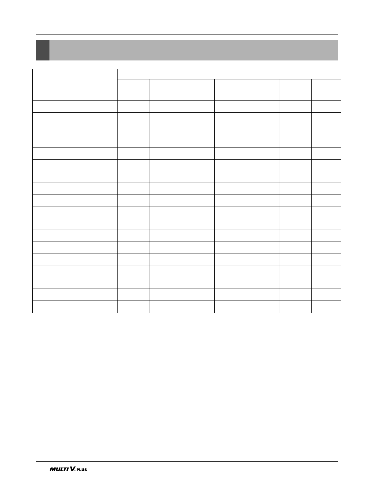
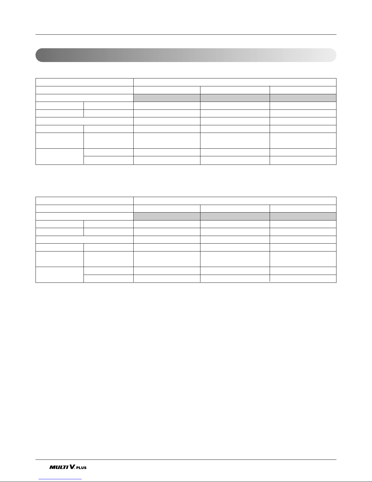
3. Combination of Outdoor Units
Combination of Outdoor Units
■ Up to a maximum 40HP are realized by combining 8, 10, 12, 14 and 16HP
■ * :3Ø, 380V, 60Hz
System Capacity Number of Units
Module
50Hz(60Hz)
56810121416
5HP 1(1) 1
6HP 1(1) 1
8HP 1(1) 1
10HP 1(1) 1
12HP 1(1) 1
14HP 1(1) 1
16HP 2(2) 2
18HP 2(2) 1 1
20HP 2(2) 2
22HP 2(2) 1 1
24HP 2(2) 2
26HP 3(2) 2 1 *(1) *(1)
28HP 3(3) 1 2
30HP 3(3) 3
32HP 3(3) 2 1
34HP 3(3) 2 1
36HP 3(3) 3
38HP 3(3) 2 1
40HP 3(3) 2 1
Service Manual 15
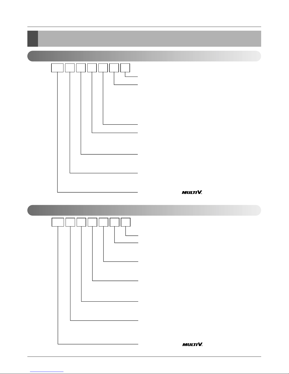
Nomenclature
LRN N 607 ASR 0
Serial Number
Combinations of functions
A:Basic function G:Low Static Motor
L:Nano Plasma(Wall Mounted)
C:Plasma(Ceiling Cassette) Q:Plasma(Low Static Duct)
ART COOL Type Panel Color
B:Blue D:Wood M:Metal R:Mirror W:White C:Cherry
SP, SV- J:Blue+Plasma K:Wood+Plasma L:Metal +Plasma
Chassis Name
Electrical Ratings
1:1Ø, 115V, 60Hz 2: 1Ø, 220V, 60Hz
6:1Ø, 220 ~ 240V, 50Hz 7: 1Ø, 100V, 50/60Hz
Total Cooling Capacity in Btu/h unit
EX) 5,000 Btu/h➞'05' 18,000 Btu/h➞'18'
Combination of Inverter Type and
Cooling Only or Heat Pump
N: AC Inverter and H/P V: AC Inverter and C/O
Indicates that this is System
Indoor Unit using the R22
LRU N 8100 ST 0
Serial Number
Multi V PLUS unit
S:2 Units Series
R:3 Units Series
Air Discharge Type
S:Side Discharge
T:Top Discharge
Electrical Ratings
8:3Ø, 380 ~ 415V, 50Hz 9: 3Ø, 380V, 60Hz
A: 3Ø, 220V, 50Hz B: 3Ø, 220V, 60Hz
Total Cooling Capacity in Horse Power(HP) unit
EX) 4.5HP➞'45' 10HP➞'100'
Combination of Inverter Type and
Cooling Only or Heat Pump
N: AC Inverter and H/P V: AC Inverter and C/O
H: H/P C: C/O
Indicates that this is System
Outdoor Unit using the R22
4. Nomenclature
4.1 Indoor Unit
4.2 Outdoor Unit

16
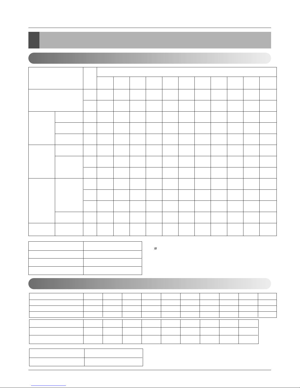
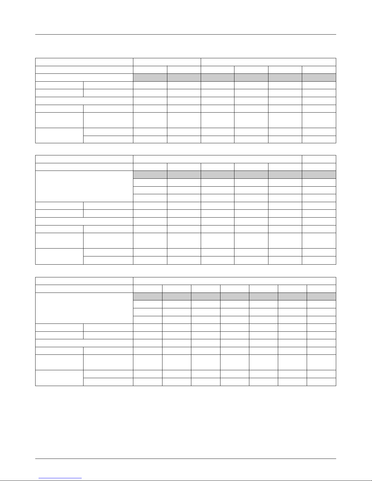
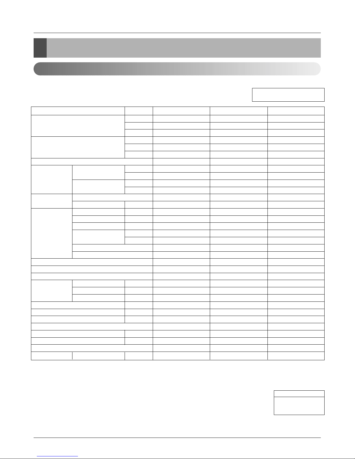
5. Outdoor Units Information
CAUTION: A ratio of the connectable Indoor Units with the Outdoor Unit : within 50 ~ 130%
Power Supply: Outdoor Unit (3Ø, 380 ~ 415V, 50Hz)
■ Cooling Only
Unit
System(HP)
Model
Product Charge kg
CF(Correction Factor) kg
Max. Connectable No. of Indoor Units
Net Weight kg(lbs)
Dimensions (W x H x D)
mm(inch)
Pipe Connections
Liquid Pipes(mm(inch))
Gas Pipes(mm(inch))
1 Outdoor Unit(Half size) 1 Outdoor Unit
568101214
LRUV508T0 LRUV608T0 LRUV808T0 LRUV1008T0 LRUV1208T0 LRUV1408T0
556101010
000-1-1-1
6 8 13 16 16 16
150(330.7) 150(330.7) 150(330.7) 300(661.4) 300(661.4) 300(661.4)
806 x 1555 x 730 806 x 1555 x 730 806 x 1555 x 730 1280 x 1555 x 730 1280 x 1555 x 730 1280 x 1555 x 730
(31.7 x 61.2 x 28.7) (31.7 x 61.2 x 28.7) (31.7 x 61.2 x 28.7) (50.4 x 61.2 x 28.7) (50.4 x 61.2 x 28.7) (50.4 x 61.2 x 28.7)
Ø9.52(3/8) Ø9.52(3/8) Ø12.7(1/2) Ø12.7(1/2) Ø12.7(1/2) Ø12.7(1/2)
Ø19.05(3/4) Ø22.2(7/8) Ø28.58(11/
8) Ø28.58(1
1
/
8) Ø28.58(1
1
/
8) Ø28.58(1
1
/
8)
Unit
System(HP)
Model
Product Charge kg
CF(Correction Factor) kg
Max. Connectable No. of Indoor Units
Net Weight kg(lbs)
Dimensions (W x H x D)
mm(inch)
Pipe Connections
Liquid Pipes(mm(inch))
Gas Pipes(mm(inch))
2 Outdoor Units
3 Outdoor Units
16 18 20 22 24 26
LRUV1608TS0 LRUV1808TS0 LRUV2008TS0 LRUV2208TS0 LRUV2408TS0 LRUV2608TR0
LRUV808TS0 LRUV1008TS0 LRUV1008TS0 LRUV1208TS0 LRUV1208TS0 LRUV1008TR0
LRUC808TS0 LRUC808TS0 LRUC1008TS0 LRUC1008TS0 LRUC1208TS0 LRUC808TR0
LRUC808TR0
10 x 2 10 x 2 10 x 2 10 x 2 10 x 2 10 x 3
-2 -2 -2 -2 -2 0
20 20 20 22 24 26
300(661.4) x 2 300(661.4) x 2 300(661.4) x 2 300(661.4) x 2 300(661.4) x 2 300(661.4) x 3
(1280 x 1555 x 730) x 2 (1280 x 1555 x 730) x 2 (1280 x 1555 x 730) x 2 (1280 x 1555 x 730) x 2 (1280 x 1555 x 730) x 2 (1280 x 1555 x 730) x 3
((50.4 x 61.2 x 28.7) x 2) ((50.4 x 61.2 x 28.7) x 2) ((50.4 x 61.2 x 28.7) x 2) ((50.4 x 61.2 x 28.7) x 2) ((50.4 x 61.2 x 28.7) x 2) ((50.4 x 61.2 x 28.7) x 3)
Ø19.05(3/4) Ø19.05(3/4) Ø19.05(3/4) Ø19.05(3/4) Ø19.05(3/4) Ø22.2(7/8)
Ø38.1(11/
2) Ø38.1(1
1
/
2) Ø38.1(1
1
/
2) Ø38.1(1
1
/
2) Ø38.1(1
1
/
2) Ø44.5(1
3
/
4)
Unit
System(HP)
Model
Product Charge kg
CF(Correction Factor) kg
Max. Connectable No. of Indoor Units
Net Weight kg(lbs)
Dimensions (W x H x D)
mm(inch)
Pipe Connections
Liquid Pipes(mm(inch))
Gas Pipes(mm(inch))
3 Outdoor Units
28 30 32 34 36 38 40
LRUV2808TR0 LRUV3008TR0 LRUV3208TR0 LRUV3408TR0 LRUV3608TR0 LRUV3808TR0 LRUV4008TR0
LRUV808TR0 LRUV1008TR0 LRUV1208TR0 LRUV1408TR0 LRUV1208TR0 LRUV1408TR0 LRUV1608TR0
LRUC1008TR0 LRUC1008TR0 LRUC1008TR0 LRUC1008TR0 LRUC1208TR0 LRUC1208TR0 LRUC1208TR0
LRUC1008TR0 LRUC1008TR0 LRUC1008TR0 LRUC1008TR0 LRUC1208TR0 LRUC1208TR0 LRUC1208TR0
10 x 3 10 x 3 10 x 3 10 x 3 10 x 3 10 x 3 10 x 3
0001122
32 32 32 34 36 38 40
300(661.4) x 3 300(661.4) x 3 300(661.4) x 3 300(661.4) x 3 300(661.4) x 3 300(661.4) x 3 300(661.4) x 3
(1280 x 1555 x 730) x 3 (1280 x 1555 x 730) x 3 (1280 x 1555 x 730) x 3 (1280 x 1555 x 730) x 3 (1280 x 1555 x 730) x 3 (1280 x 1555 x 730) x 3 (1280 x 1555 x 730) x 3
((50.4 x 61.2 x 28.7) x 3) ((50.4 x 61.2 x 28.7) x 3) ((50.4 x 61.2 x 28.7) x 3) ((50.4 x 61.2 x 28.7) x 3) ((50.4 x 61.2 x 28.7) x 3) ((50.4 x 61.2 x 28.7) x 3) ((50.4 x 61.2 x 28.7) x 3)
Ø22.2(7/8) Ø22.2(7/8) Ø22.2(7/8) Ø22.2(7/8) Ø22.2(7/8) Ø22.2(7/8) Ø22.2(7/8)
Ø44.5(1
3
/4) Ø44.5(13/4) Ø44.5(13/4) Ø44.5(13/4) Ø44.5(13/4) Ø44.5(13/4) Ø44.5(13/4)
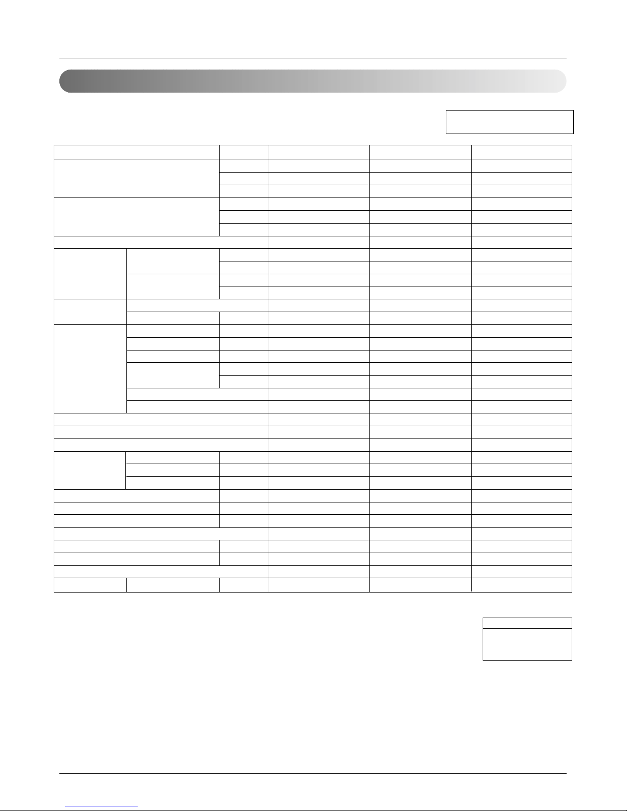
Service Manual 17
■ Heat Pump
Unit
System(HP)
Model
Product Charge kg
CF(Correction Factor) kg
Max. Connectable No. of Indoor Units
Net Weight kg(lbs)
Dimensions (W x H x D)
mm(inch)
Pipe Connections
Liquid Pipes(mm(inch))
Gas Pipes(mm(inch))
1 Outdoor Unit(Half size)
1 Outdoor Unit
568101214
LRUN508T0 LRUN608T0 LRUN808T0 LRUN1008T0 LRUN1208T0 LRUN1408T0
5 5 10 10 10 10
0 0 -1 -1 -1 -1
6 8 13 16 16 16
150(330.7) 150(330.7) 300(661.4) 300(661.4) 300(661.4) 300(661.4)
806 x 1555 x 730 806 x 1555 x 730 1280 x 1555 x 730 1280 x 1555 x 730 1280 x 1555 x 730 1280 x 1555 x 730
(
31.7 x 61.2 x 28.7) (31.7 x 61.2 x 28.7) (50.4 x 61.2 x 28.7) (50.4 x 61.2 x 28.7) (50.4 x 61.2 x 28.7) (50.4 x 61.2 x 28.7)
Ø9.52(3/8) Ø9.52(3/8) Ø12.7(1/2) Ø12.7(1/2) Ø12.7(1/2) Ø12.7(1/2)
Ø19.05(3/4) Ø22.2(7/8) Ø28.58(11/8
) Ø28.58(1
1
/8
) Ø28.58(1
1
/8
) Ø28.58(1
1
/8
)
Unit
System(HP)
Model
Product Charge kg
CF(Correction Factor) kg
Max. Connectable No. of Indoor Units
Net Weight kg(lbs)
Dimensions (W x H x D)
mm(inch)
Pipe Connections
Liquid Pipes(mm(inch))
Gas Pipes(mm(inch))
2 Outdoor Units
3 Outdoor Units
16 18 20 22 24 26
LRUN1608TS0 LRUN1808TS0 LRUN2008TS0 LRUN2208TS0 LRUN2408TS0 LRUN2608TR0
LRUN808TS0 LRUN1008TS0 LRUN1008TS0 LRUN1208TS0 LRUN1208TS0 LRUN1008TR0
LRUH808TS0 LRUH808TS0 LRUH1008TS0 LRUH1008TS0 LRUH1208TS0 LRUH808TR0
LRUH808TR0
10 x 2 10 x 2 10 x 2 10 x 2 10 x 2 10 x 3
-2 -2 -2 -2 -2 0
20 20 20 22 24 26
300(661.4) x 2 300(661.4) x 2 300(661.4) x 2 300(661.4) x 2 300(661.4) x 2 300(661.4) x 3
(1280 x 1555 x 730) x 2 (1280 x 1555 x 730) x 2 (1280 x 1555 x 730) x 2 (1280 x 1555 x 730) x 2 (1280 x 1555 x 730) x 2 (1280 x 1555 x 730) x 3
((50.4 x 61.2 x 28.7) x 2) ((50.4 x 61.2 x 28.7) x 2) ((50.4 x 61.2 x 28.7) x 2) ((50.4 x 61.2 x 28.7) x 2) ((50.4 x 61.2 x 28.7) x 2) ((50.4 x 61.2 x 28.7) x 3)
Ø19.05(3/4) Ø19.05(3/4) Ø19.05(3/4) Ø19.05(3/4) Ø19.05(3/4) Ø22.2(7/8)
Ø38.1(11/2) Ø38.1(11/2) Ø38.1(11/2) Ø38.1(11/2) Ø38.1(11/2) Ø44.5(13/4)
Unit
System(HP)
Model
Product Charge kg
CF(Correction Factor) kg
Max. Connectable No. of Indoor Units
Net Weight kg(lbs)
Dimensions (W x H x D)
mm(inch)
Pipe Connections
Liquid Pipes(mm(inch))
Gas Pipes(mm(inch))
3 Outdoor Units
28 30 32 34 36 38 40
LRUN2808TR0 LRUN3008TR0 LRUN3208TR0 LRUN3408TR0 LRUN3608TR0 LRUN3808TR0 LRUN4008TR0
LRUN808TR0 LRUN1008TR0 LRUN1208TR0 LRUN1408TR0 LRUN1208TR0 LRUN1408TR0 LRUN1608TR0
LRUH1008TR0 LRUH1008TR0 LRUH1008TR0 LRUH1008TR0 LRUH1208TR0 LRUH1208TR0 LRUH1208TR0
LRUH1008TR0 LRUH1008TR0 LRUH1008TR0 LRUH1008TR0 LRUH1208TR0 LRUH1208TR0 LRUH1208TR0
10 x 3 10 x 3 10 x 3 10 x 3 10 x 3 10 x 3 10 x 3
0001122
32 32 32 34 36 38 40
300(661.4) x 3 300(661.4) x 3 300(661.4) x 3 300(661.4) x 3 300(661.4) x 3 300(661.4) x 3 300(661.4) x 3
(1280 x 1555 x 730) x 3 (1280 x 1555 x 730) x 3 (1280 x 1555 x 730) x 3 (1280 x 1555 x 730) x 3 (1280 x 1555 x 730) x 3 (1280 x 1555 x 730) x 3 (1280 x 1555 x 730) x 3
((50.4 x 61.2 x 28.7) x 3) ((50.4 x 61.2 x 28.7) x 3) ((50.4 x 61.2 x 28.7) x 3) ((50.4 x 61.2 x 28.7) x 3) ((50.4 x 61.2 x 28.7) x 3) ((50.4 x 61.2 x 28.7) x 3) ((50.4 x 61.2 x 28.7) x 3)
Ø22.2(7/8) Ø22.2(7/8) Ø22.2(7/8) Ø22.2(7/8) Ø22.2(7/8) Ø22.2(7/8) Ø22.2(7/8)
Ø44.5(1
3
/4
) Ø44.5(1
3
/4
) Ø44.5(1
3
/4
) Ø44.5(1
3
/4
) Ø44.5(1
3
/4
) Ø44.5(1
3
/4
) Ø44.5(1
3
/4
)
18
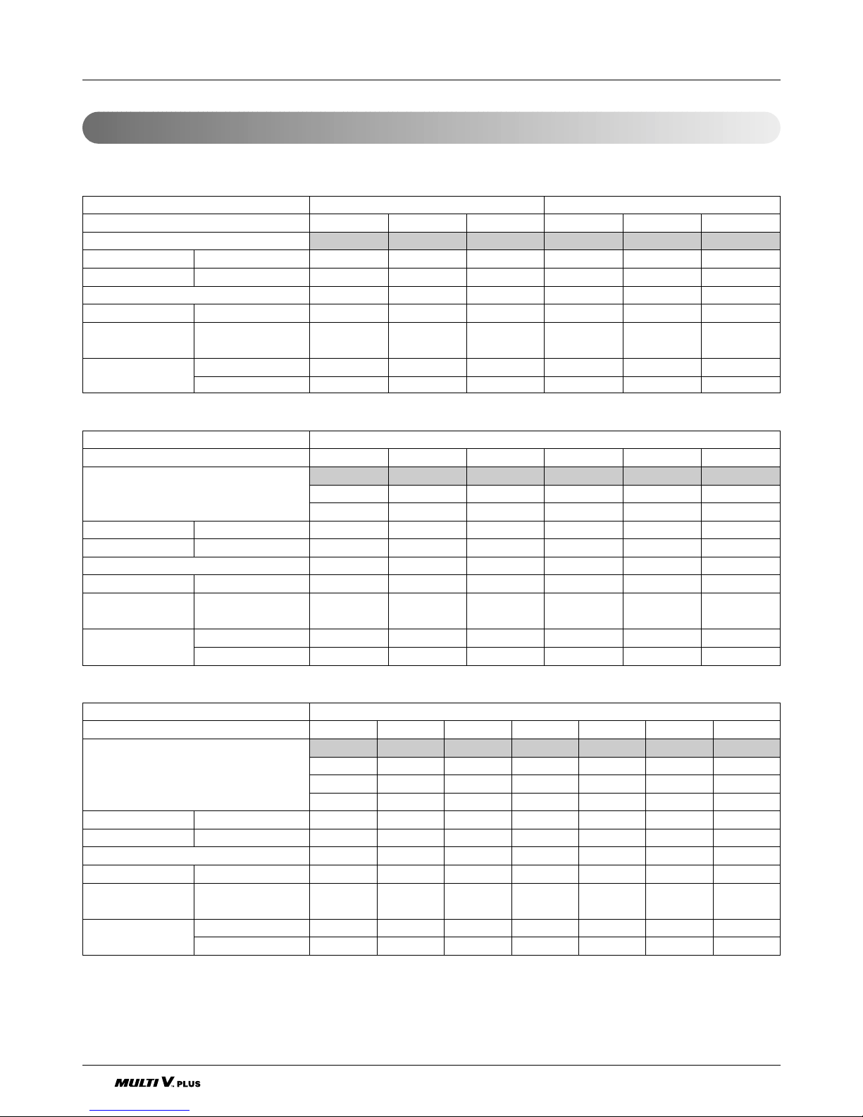
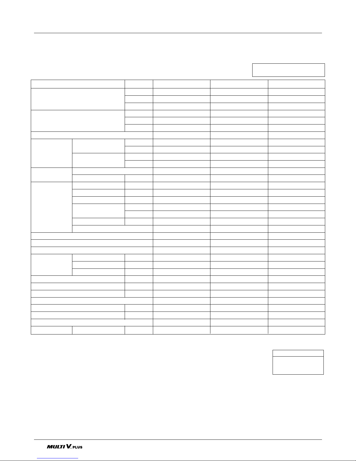
Power Supply: Outdoor Unit (3Ø, 380V, 60Hz)
■ Cooling Only
Unit
System(HP)
Model
Product Charge kg
CF(Correction Factor) kg
Max. Connectable No. of Indoor Units
Net Weight kg(lbs)
Dimensions (W x H x D)
mm(inch)
Pipe Connections
Liquid Pipes(mm(inch))
Gas Pipes(mm(inch))
1 Outdoor Unit(Half size) 1 Outdoor Unit
568101214
LRUV509T0 LRUV609T0 LRUV809T0 LRUV1009T0 LRUV1209T0 LRUV1409T0
556101010
000-1-1-1
6 8 13 16 16 16
150(330.7) 150(330.7) 150(330.7) 300(661.4) 300(661.4) 300(661.4)
806 x 1555 x 730 806 x 1555 x 730 806 x 1555 x 730 1280 x 1555 x 730 1280 x 1555 x 730 1280 x 1555 x 730
(31.7 x 61.2 x 28.7) (31.7 x 61.2 x 28.7) (31.7 x 61.2 x 28.7) (50.4 x 61.2 x 28.7) (50.4 x 61.2 x 28.7) (50.4 x 61.2 x 28.7)
Ø9.52(3/8) Ø9.52(3/8) Ø12.7(1/2) Ø12.7(1/2) Ø12.7(1/2) Ø12.7(1/2)
Ø19.05(3/4) Ø22.2(7/8) Ø28.58(11/8) Ø28.58(11/8) Ø28.58(11/8) Ø28.58(11/8)
Unit
System(HP)
Model
Product Charge kg
CF(Correction Factor) kg
Max. Connectable No. of Indoor Units
Net Weight kg(lbs)
Dimensions (W x H x D)
mm(inch)
Pipe Connections
Liquid Pipes(mm(inch))
Gas Pipes(mm(inch))
2 Outdoor Units
16 18 20 22 24 26
LRUV1609TS0 LRUV1809TS0 LRUV2009TS0 LRUV2209TS0 LRUV2409TS0 LRUV2609TS0
LRUV809TS0 LRUV1009TS0 LRUV1009TS0 LRUV1209TS0 LRUV1209TS0 LRUV1409TS0
LRUC809TS0 LRUC809TS0 LRUC1009TS0 LRUC1009TS0 LRUC1209TS0 LRUC1209TS0
10 x 2 10 x 2 10 x 2 10 x 2 10 x 2 10 x 2
-2 -2 -2 -2 -2 -1
20 20 20 22 24 26
300(661.4) x 2 300(661.4) x 2 300(661.4) x 2 300(661.4) x 2 300(661.4) x 2 300(661.4) x 2
(1280 x 1555 x 730) x 2 (1280 x 1555 x 730) x 2 (1280 x 1555 x 730) x 2 (1280 x 1555 x 730) x 2 (1280 x 1555 x 730) x 2 (1280 x 1555 x 730) x 2)
((50.4 x 61.2 x 28.7) x 2) ((50.4 x 61.2 x 28.7) x 2) ((50.4 x 61.2 x 28.7) x 2) ((50.4 x 61.2 x 28.7) x 2) ((50.4 x 61.2 x 28.7) x 2) ((50.4 x 61.2 x 28.7) x 2)
Ø19.05(3/4) Ø19.05(3/4) Ø19.05(3/4) Ø19.05(3/4) Ø19.05(3/4) Ø19.05(3/4)
Ø38.1(11/2) Ø38.1(11/2) Ø38.1(11/2) Ø38.1(11/2) Ø38.1(11/2) Ø38.1(11/2)
Unit
System(HP)
Model
Product Charge kg
CF(Correction Factor) kg
Max. Connectable No. of Indoor Units
Net Weight kg(lbs)
Dimensions (W x H x D)
mm(inch)
Pipe Connections
Liquid Pipes(mm(inch))
Gas Pipes(mm(inch))
3 Outdoor Units
28 30 32 34 36 38 40
LRUV2809TR0 LRUV3009TR0 LRUV3209TR0 LRUV3409TR0 LRUV3609TR0 LRUV3809TR0 LRUV4008TR0
LRUV809TR0 LRUV1009TR0 LRUV1209TR0 LRUV1409TR0 LRUV1209TR0 LRUV1409TR0 LRUV1609TR0
LRUC1009TR0 LRUC1009TR0 LRUC1009TR0 LRUC1009TR0 LRUC1209TR0 LRUC1209TR0 LRUC1209TR0
LRUC1009TR0 LRUC1009TR0 LRUC1009TR0 LRUC1009TR0 LRUC1209TR0 LRUC1209TR0 LRUC1209TR0
10 x 3 10 x 3 10 x 3 10 x 3 10 x 3 10 x 3 10 x 3
0001122
32 32 32 34 36 38 40
300(661.4) x 3 300(661.4) x 3 300(661.4) x 3 300(661.4) x 3 300(661.4) x 3 300(661.4) x 3 300(661.4) x 3
(1280 x 1555 x 730) x 3 (1280 x 1555 x 730) x 3 (1280 x 1555 x 730) x 3 (1280 x 1555 x 730) x 3 (1280 x 1555 x 730) x 3 (1280 x 1555 x 730) x 3 (1280 x 1555 x 730) x 3
((50.4 x 61.2 x 28.7) x 3) ((50.4 x 61.2 x 28.7) x 3) ((50.4 x 61.2 x 28.7) x 3) ((50.4 x 61.2 x 28.7) x 3) ((50.4 x 61.2 x 28.7) x 3) ((50.4 x 61.2 x 28.7) x 3) ((50.4 x 61.2 x 28.7) x 3)
Ø22.2(7/8) Ø22.2(7/8) Ø22.2(7/8) Ø22.2(7/8) Ø22.2(7/8) Ø22.2(7/8) Ø22.2(7/8)
Ø
44.5(1
3
/
4)
Ø
44.5(1
3
/
4)
Ø
44.5(1
3
/
4)
Ø
44.5(1
3
/
4)
Ø
44.5(1
3
/
4)
Ø
44.5(1
3
/
4)
Ø
44.5(1
3
/
4)

Service Manual 19
■ Heat Pump
Unit
System(HP)
Model
Product Charge kg
CF(Correction Factor) kg
Max. Connectable No. of Indoor Units
Net Weight kg(lbs)
Dimensions (W x H x D)
mm(inch)
Pipe Connections
Liquid Pipes(mm(inch))
Gas Pipes(mm(inch))
1 Outdoor Unit(Half size)
1 Outdoor Unit
568101214
LRUN509T0 LRUN609T0 LRUN809T0 LRUN1009T0 LRUN1209T0 LRUN1409T0
5 5 10 10 10 10
0 0 -1 -1 -1 -1
6 8 13 16 16 16
150(330.7) 150(330.7) 300(661.4) 300(661.4) 300(661.4) 300(661.4)
806 x 1555 x 730 806 x 1555 x 730 1280 x 1555 x 730 1280 x 1555 x 730 1280 x 1555 x 730 1280 x 1555 x 730
(31.7 x 61.2 x 28.7) (31.7 x 61.2 x 28.7) (50.4 x 61.2 x 28.7) (50.4 x 61.2 x 28.7) (50.4 x 61.2 x 28.7) (50.4 x 61.2 x 28.7
Ø9.52(3/8) Ø9.52(3/8) Ø12.7(1/2) Ø12.7(1/2) Ø12.7(1/2) Ø12.7(1/2)
Ø19.05(3/4) Ø22.2(7/8) Ø28.58(11/8) Ø28.58(11/8) Ø28.58(11/8) Ø28.58(11/8)
Unit
System(HP)
Model
Product Charge kg
CF(Correction Factor) kg
Max. Connectable No. of Indoor Units
Net Weight kg(lbs)
Dimensions (W x H x D)
mm(inch)
Pipe Connections
Liquid Pipes(mm(inch))
Gas Pipes(mm(inch))
2 Outdoor Units
16 18 20 22 24 26
LRUN1609TS0 LRUN1809TS0 LRUN2009TS0 LRUN2209TS0 LRUN2409TS0 LRUN2609TS0
LRUN809TS0 LRUN1009TS0 LRUN1009TS0 LRUN1209TS0 LRUN1209TS0 LRUN1409TS0
LRUH809TS0 LRUH809TS0 LRUH1009TS0 LRUH1009TS0 LRUH1209TS0 LRUH1209TS0
10 x 2 10 x 2 10 x 2 10 x 2 10 x 2 10 x 2
-2 -2 -2 -2 -2 -1
20 20 20 22 24 26
300(661.4) x 2 300(661.4) x 2 300(661.4) x 2 300(661.4) x 2 300(661.4) x 2 300(661.4) x 2
(1280 x 1555 x 730) x 2 (1280 x 1555 x 730) x 2 (1280 x 1555 x 730) x 2 (1280 x 1555 x 730)) x 2 (1280 x 1555 x 730) x 2 (1280 x 1555 x 730) x 2
((50.4 x 61.2 x 28.7) x 2) ((50.4 x 61.2 x 28.7) x 2) ((50.4 x 61.2 x 28.7) x 2) ((50.4 x 61.2 x 28.7) x 2) ((50.4 x 61.2 x 28.7) x 2) ((50.4 x 61.2 x 28.7) x 2)
Ø19.05(3/4) Ø19.05(3/4) Ø19.05(3/4) Ø19.05(3/4) Ø19.05(3/4) Ø19.05(3/4)
Ø38.1(11/
2) Ø38.1(1
1
/
2) Ø38.1(1
1
/
2) Ø38.1(1
1
/
2) Ø38.1(1
1
/
2) Ø38.1(1
1
/
2)
Unit
System(HP)
Model
Product Charge kg
CF(Correction Factor) kg
Max. Connectable No. of Indoor Units
Net Weight kg(lbs)
Dimensions (W x H x D)
mm(inch)
Pipe Connections
Liquid Pipes(mm(inch))
Gas Pipes(mm(inch))
3 Outdoor Units
28 30 32 34 36 38 40
LRUN2809TR0 LRUN3009TR0 LRUN3209TR0 LRUN3409TR0 LRUN3609TR0 LRUN3809TR0 LRUN4009TR0
LRUN809TR0 LRUN1009TR0 LRUN1209TR0 LRUN1409TR0 LRUN1209TR0 LRUN1409TR0 LRUN1609TR0
LRUH1009TR0 LRUH1009TR0 LRUH1009TR0 LRUH1009TR0 LRUH1209TR0 LRUH1209TR0 LRUH1209TR0
LRUH1009TR0 LRUH1009TR0 LRUH1009TR0 LRUH1009TR0 LRUH1209TR0 LRUH1209TR0 LRUH1209TR0
10 x 3 10 x 3 10 x 3 10 x 3 10 x 3 10 x 3 10 x 3
0001122
32 32 32 34 36 38 40
300(661.4) x 3 300(661.4) x 3 300(661.4) x 3 300(661.4) x 3 300(661.4) x 3 300(661.4) x 3 300(661.4) x 3
(1280 x 1555 x 730) x 3 (1280 x 1555 x 730) x 3 (1280 x 1555 x 730) x 3 (1280 x 1555 x 730) x 3 (1280 x 1555 x 730) x 3 (1280 x 1555 x 730) x 3 (1280 x 1555 x 730) x 3
((50.4 x 61.2 x 28.7) x 3) ((50.4 x 61.2 x 28.7) x 3) ((50.4 x 61.2 x 28.7) x 3) ((50.4 x 61.2 x 28.7) x 3) ((50.4 x 61.2 x 28.7) x 3) ((50.4 x 61.2 x 28.7) x 3) ((50.4 x 61.2 x 28.7) x 3)
Ø22.2(7/8) Ø22.2(7/8) Ø22.2(7/8) Ø22.2(7/8) Ø22.2(7/8) Ø22.2(7/8) Ø22.2(7/8)
Ø
44.5(13/4)Ø44.5(13/4)Ø44.5(13/4)Ø44.5(13/4)Ø44.5(13/4)Ø44.5(13/4)Ø44.5(13/4)
20
Power Supply: Outdoor Unit (3Ø, 220V, 60Hz)
■ Cooling Only
■ Heat Pump
Unit
System(HP)
Model
Product Charge kg
CF(Correction Factor) kg
Max. Connectable No. of Indoor Units
Net Weight kg(lbs)
Dimensions (W x H x D)
mm(inch)
Pipe Connections
Liquid Pipes(mm(inch))
Gas Pipes(mm(inch))
1 Outdoor Unit
81012
LRUV80BT0 LRUV100BT0 LRUV120BT0
10 10 10
-1 -1 -1
13 16 16
300(661.4) 300(661.4) 300(661.4)
1280 x 1555 x 730 1280 x 1555 x 730 1280 x 1555 x 730
(50.4 x 61.2 x 28.7) (50.4 x 61.2 x 28.7) (50.4 x 61.2 x 28.7)
Ø12.7(1/2) Ø12.7(1/2) Ø12.7(1/2)
Ø28.58(11/8) Ø28.58(11/8) Ø28.58(11/8)
Unit
System(HP)
Model
Product Charge kg
CF(Correction Factor) kg
Max. Connectable No. of Indoor Units
Net Weight kg(lbs)
Dimensions (W x H x D)
mm(inch)
Pipe Connections
Liquid Pipes(mm(inch))
Gas Pipes(mm(inch))
1 Outdoor Unit
810 12
LRUN80BT0 LRUN100BT0 LRUN120BT0
10 10 10
-1 -1 -1
13 16 16
300(661.4) 300(661.4) 300(661.4)
1280 x 1555 x 730 1280 x 1555 x 730 1280 x 1555 x 730
(50.4 x 61.2 x 28.7) (50.4 x 61.2 x 28.7) (50.4 x 61.2 x 28.7)
Ø12.7(1/2) Ø12.7(1/2) Ø12.7(1/2)
Ø28.58(11/
8) Ø28.58(1
1
/
8) Ø28.58(1
1
/
8)

Service Manual 21
Indoor Unit
Indoor Units

22 Indoor Unit
Ceiling Mounted Cassette Type (1Way)
1. Specifications.............................................................................23
2. Functions ....................................................................................27
3. Operation Details........................................................................28
4. Dimensional Drawings...............................................................30
5. Piping Diagrams.........................................................................31
6. Wiring Diagrams.........................................................................32
Service Manual 23
1. Specifications
Specifications
1.1.1 Cooling Only
Cooling Only (50Hz)
1.1 50Hz
Model Unit
W
Cooling Capacity kcal/h
Btu/h
W
Heating Capacity kcal/h
Btu/h
Casing
Body
mm
Dimensions (W*H*D)
inch
Front Panel
mm
inch
Coil
Rows x Columns x FPI
Face Area m
2
Type
Motor Output W
Running Current A
Fan Air Flow Rate(H/M/L) cmm
cfm
Drive
Speed control
Temperature Control
Sound Absorbing Thermal Insulation Material
Safety Device
Liquid Side mm(inch)
Pipe Connections
Gas Side mm(inch)
Drain Pipe(OD)
mm
Net Weight kg(lbs)
Noise Level
(Sound Press, 1.5m, H/M/L)
dBA±3
Power Supply Ø / V / Hz
Refrigerant Control
Power cable mm
2
Transmission cable mm
2
Panel Color
Stuffing Quantity Without S/parts
20/40ft
LRNV076TCA(C)0 LRNV096TCA(C)0 LRNV126TCA(C)0
2,100 2,600 3,500
1,806 2,235 3,009
7,165 8,871 11,942
-- -
-- -
-- -
Galvanized Steel Plate Galvanized Steel Plate Galvanized Steel Plate
860*390*180 860*390*180 860*390*180
33.8*15.3*7.0 33.8*15.3*7.0 33.8*15.3*7.0
1050*480*30 1050*480*30 1050*480*30
41.3*18.9*1.2 41.3*18.9*1.2 41.3*18.9*1.2
2*12*18 2*12*21 2*12*21
0.17 0.17 0.17
Cross Flow Fan Cross Flow Fan Cross Flow Fan
14 14 14
0.22 0.22 0.22
6/5/4 7/6/5 10/9/8
212/177/141 247/212/177 353/318/283
Direct Direct Direct
Phase Control Phase Control Phase Control
Microprocessor, Thermostat for cooling Microprocessor, Thermostat for cooling Microprocessor, Thermostat for cooling
Foamed polystrene Foamed polystrene Foamed polystrene
Fuse, Thermal Fuse for Fan Motor Fuse, Thermal Fuse for Fan Motor Fuse, Thermal Fuse for Fan Motor
Ø6.35(1/4) Ø6.35(1/4) Ø6.35(1/4)
Ø12.7(1/2) Ø12.7(1/2) Ø12.7(1/2)
32.0 32.0 32.0
17(37.5) 17(37.5) 17(37.5)
35/32/29 37/34/31 39/36/35
1 / 220 ~ 240V / 50Hz 1 / 220 ~ 240V / 50Hz 1 / 220 ~ 240V / 50Hz
LEV LEV LEV
CV2.0 X 3C CV2.0 X 3C CV2.0 X 3C
CVV-SB 1.25 X 2C CVV-SB 1.25 X 2C CVV-SB 1.25 X 2C
White White White
263/539 263/539 263/539
Notes:-
1. Capacities are based on the following conditions:
Cooling • Indoor temp. 27°C[80.6°F]DB/ 19°C[66.2°F]WB
• Outdoor temp. 35°C[95°F]DB/ 24°C[75.2°F]WB
• Interconnecting Piping Length 7.5m
• Level Difference of Zero
2. Capacities are net capacities
3. Due to our policy of innovation some specifications may be changed without notification
4. L.E.V.: Linear Expansion Valve
Conversion Formula
Kcal/h= kW x 860
Btu/h = kW x 3412
cfm = m
3
/min x 35.3

24 Indoor Unit
Specifications
2.1.2 Heat Pump
Notes:-
1. Capacities are based on the following conditions:
Cooling • Indoor temp. 27°C[80.6°F]DB/ 19°C[66.2°F]WB
• Outdoor temp. 35°C[95°F]DB/ 24°C[75.2°F]WB
• Interconnecting Piping Length 7.5m
• Level Difference of Zero
Heating • Indoor temp. 20°C[68°F]DB/ 15°C[59°F]WB
• Outdoor temp. 7°C[44.6°F]DB/ 6°C[42.8°F]WB
• Interconnecting Piping Length 7.5m
• Level Difference of Zero
2. Capacities are net capacities
3. Due to our policy of innovation some specifications may be changed without notification
4. L.E.V.:Linear Expansion Valve
Conversion Formula
Kcal/h= kW x 860
Btu/h = kW x 3412
cfm = m
3
/min x 35.3
Heat Pump (50Hz)
Model Unit
W
Cooling Capacity kcal/h
Btu/h
W
Heating Capacity kcal/h
Btu/h
Casing
Body
mm
Dimensions (W*H*D)
inch
Front Panel
mm
inch
Coil
Rows x Columns x FPI
Face Area m
2
Type
Motor Output W
Running Current A
Fan Air Flow Rate(H/M/L) cmm
cfm
Drive
Speed control
Temperature Control
Sound Absorbing Thermal Insulation Material
Safety Device
Liquid Side mm(inch)
Pipe Connections
Gas Side mm(inch)
Drain Pipe(OD)
mm
Net Weight kg(lbs)
Noise Level
(Sound Press, 1.5m, H/M/L)
dBA±3
Power Supply Ø / V / Hz
Refrigerant Control
Power cable mm
2
Transmission cable mm
2
Panel Color
Stuffing Quantity Without S/parts
20/40ft
LRNN076TCA(C)0 LRNN096TCA(C)0 LRNN126TCA(C)0
2,100 2,600 3,500
1,806 2,235 3,009
7,165 8,871 11,942
2,363 2,925 3,938
2,031 2,515 3,385
8,061 9,980 13,435
Galvanized Steel Plate Galvanized Steel Plate Galvanized Steel Plate
860*390*180 860*390*180 860*390*180
33.8*15.3*7.0 33.8*15.3*7.0 33.8*15.3*7.0
1050*480*30 1050*480*30 1050*480*30
41.3*18.9*1.2 41.3*18.9*1.2 41.3*18.9*1.2
2*12*18 2*12*21 2*12*21
0.17 0.17 0.17
Cross Flow Fan Cross Flow Fan Cross Flow Fan
14 14 14
0.22 0.22 0.22
6/5/4 7/6/5 10/9/8
212/177/141 247/212/177 353/318/283
Direct Direct Direct
Phase Control Phase Control Phase Control
Microprocessor, Thermostat for cooling and heating Microprocessor, Thermostat for cooling and heating Microprocessor, Thermostat for cooling and heating
Foamed polystrene Foamed polystrene Foamed polystrene
Fuse, Thermal Fuse for Fan Motor Fuse, Thermal Fuse for Fan Motor Fuse, Thermal Fuse for Fan Motor
Ø6.35(1/4) Ø6.35(1/4) Ø6.35(1/4)
Ø12.7(1/2) Ø12.7(1/2) Ø12.7(1/2)
32.0 32.0 32.0
17(37.5) 17(37.5) 17(37.5)
35/32/29 37/34/31 39/36/35
1 / 220 ~ 240 / 50Hz 1 / 220 ~ 240 / 50Hz 1 / 220 ~ 240 / 50Hz
LEV LEV LEV
CV2.0 X 3C CV2.0 X 3C CV2.0 X 3C
CVV-SB 1.25 X 2C CVV-SB 1.25 X 2C CVV-SB 1.25 X 2C
White White White
263/539 263/539 263/539
Service Manual 25
Cooling Only(60Hz)
1.2.1 Cooling Only
1.2 60Hz
Specifications
Notes:-
1. Capacities are based on the following conditions:
Cooling • Indoor temp. 27°C[80.6°F]DB/ 19°C[66.2°F]WB
• Outdoor temp. 35°C[95°F]DB/ 24°C[75.2°F]WB
• Interconnecting Piping Length 7.5m
• Level Difference of Zero
2. Capacities are net capacities
3. Due to our policy of innovation some specifications may be changed without notification
4. L.E.V.:Linear Expansion Valve
Conversion Formula
Kcal/h= kW x 860
Btu/h = kW x 3412
cfm = m
3
/min x 35.3
Model Unit
W
Cooling Capacity kcal/h
Btu/h
W
Heating Capacity kcal/h
Btu/h
Casing
Body
mm
Dimensions (W*H*D)
inch
Front Panel
mm
inch
Coil
Rows x Columns x FPI
Face Area m
2
Type
Motor Output W
Running Current A
Fan Air Flow Rate(H/M/L) cmm
cfm
Drive
Speed control
Temperature Control
Sound Absorbing Thermal Insulation Material
Safety Device
Liquid Side mm(inch)
Pipe Connections
Gas Side mm(inch)
Drain Pipe(OD)
mm
Net Weight kg(lbs)
Noise Level
(Sound Press, 1.5m, H/M/L)
dBA±3
Power Supply Ø / V / Hz
Refrigerant Control
Power cable mm
2
Transmission cable mm
2
Panel Color
Stuffing Quantity Without S/parts
20/40ft
LRNV072TCA(C)0 LRNV092TCA(C)0 LRNV122TCA(C)0
2,100 2,600 3,500
1,806 2,235 3,009
7,165 8,871 11,942
---
---
---
Galvanized Steel Plate Galvanized Steel Plate Galvanized Steel Plate
860*390*180 860*390*180 860*390*180
33.8*15.3*7.0 33.8*15.3*7.0 33.8*15.3*7.0
1050*480*30 1050*480*30 1050*480*30
41.3*18.9*1.2 41.3*18.9*1.2 41.3*18.9*1.2
2*12*18 2*12*21 2*12*21
0.17 0.17 0.17
Cross Flow Fan Cross Flow Fan Cross Flow Fan
14 14 14
0.22 0.22 0.22
6/5/4 7/6/5 10/9/8
212/177/141 247/212/177 353/318/283
Direct Direct Direct
Phase Control Phase Control Phase Control
Microprocessor, Thermostat for cooling Microprocessor, Thermostat for cooling Microprocessor, Thermostat for cooling
Foamed polystrene Foamed polystrene Foamed polystrene
Fuse, Thermal Fuse for Fan Motor Fuse, Thermal Fuse for Fan Motor Fuse, Thermal Fuse for Fan Motor
Ø6.35(1/4) Ø6.35(1/4) Ø6.35(1/4)
Ø12.7(1/2) Ø12.7(1/2) Ø12.7(1/2)
32.0 32.0 32.0
17(37.5) 17(37.5) 17(37.5)
35/32/29 37/34/31 39/36/35
1 / 220 / 60Hz 1 / 220 / 60Hz 1 / 220 / 60Hz
LEV LEV LEV
CV2.0 X 3C CV2.0 X 3C CV2.0 X 3C
CVV-SB 1.25 X 2C CVV-SB 1.25 X 2C CVV-SB 1.25 X 2C
White White White
263/539 263/539 263/539
26 Indoor Unit
Specifications
2.2.2 Heat Pump
Notes:-
1. Capacities are based on the following conditions:
Cooling • Indoor temp. 27°C[80.6°F]DB/ 19°C[66.2°F]WB
• Outdoor temp. 35°C[95°F]DB/ 24°C[75.2°F]WB
• Interconnecting Piping Length 7.5m
• Level Difference of Zero
Heating • Indoor temp. 20°C[68°F]DB/ 15°C[59°F]WB
• Outdoor temp. 7°C[44.6°F]DB/ 6°C[42.8°F]WB
• Interconnecting Piping Length 7.5m
• Level Difference of Zero
2. Capacities are net capacities
3. Due to our policy of innovation some specifications may be changed without notification
4. L.E.V.:Linear Expansion Valve
Conversion Formula
kcal/h = kW x 860
Btu/h = kW x 3412
cfm = m
3
/min x 35.3
Heat Pump (60Hz)
Model Unit
W
Cooling Capacity kcal/h
Btu/h
W
Heating Capacity kcal/h
Btu/h
Casing
Body
mm
Dimensions (W*H*D)
inch
Front Panel
mm
inch
Coil
Rows x Columns x FPI
Face Area m
2
Type
Motor Output W
Running Current A
Fan Air Flow Rate(H/M/L) cmm
cfm
Drive
Speed control
Temperature Control
Sound Absorbing Thermal Insulation Material
Safety Device
Liquid Side mm(inch)
Pipe Connections
Gas Side mm(inch)
Drain Pipe(OD))
mm
Net Weight kg(lbs)
Noise Level
(Sound Press, 1.5m, H/M/L)
dBA±3
Power Supply Ø / V / Hz
Refrigerant Control
Power cable mm
2
Transmission cable mm
2
Panel Color
Stuffing Quantity Without S/parts
20/40ft
LRNN072TCA(C)0 LRNN092TCA(C)0 LRNN122TCA(C)0
2,100 2,600 3,500
1,806 2,235 3,009
7,165 8,871 11,942
2,363 2,925 3,938
2,031 2,515 3,385
8,061 9,980 13,435
Galvanized Steel Plate Galvanized Steel Plate Galvanized Steel Plate
860*390*180 860*390*180 860*390*180
33.8*15.3*7.0 33.8*15.3*7.0 33.8*15.3*7.0
1050*480*30 1050*480*30 1050*480*30
41.3*18.9*1.2 41.3*18.9*1.2 41.3*18.9*1.2
2*12*18 2*12*21 2*12*21
0.17 0.17 0.17
Cross Flow Fan Cross Flow Fan Cross Flow Fan
14 14 14
0.22 0.22 0.22
6/5/4 7/6/5 10/9/8
212/177/141 247/212/177 353/318/283
Direct Direct Direct
Phase Control Phase Control Phase Control
Microprocessor, Thermostat for cooling and heating Microprocessor, Thermostat for cooling and heating Microprocessor, Thermostat for cooling and heating
Foamed polystrene Foamed polystrene Foamed polystrene
Fuse, Thermal Fuse for Fan Motor Fuse, Thermal Fuse for Fan Motor Fuse, Thermal Fuse for Fan Motor
Ø6.35(1/4) Ø6.35(1/4) Ø6.35(1/4)
Ø12.7(1/2) Ø12.7(1/2) Ø12.7(1/2)
32.0 32.0 32.0
17(37.5) 17(37.5) 17(37.5)
35/32/29 37/34/31 39/36/35
1 / 220 / 60Hz 1 / 220 / 60Hz 1 / 220 / 60Hz
LEV LEV LEV
CV2.0 X 3C CV2.0 X 3C CV2.0 X 3C
CVV-SB 1.25 X 2C CVV-SB 1.25 X 2C CVV-SB 1.25 X 2C
White White White
263/539 263/539 263/539

Service Manual 27
Functions
2. Functions
Indoor Unit
Operation ON/OFF by Remote controller
Sensing the Room Temperature
Room temperature control
Starting Current Control
Time Delay Safety Control
Indoor Fan Speed Control
Soft Dry Operation Mode
Airflow Direction Control
Deice (defrost) control (Heating)
Auto Restart
Hot-start Control (Heating)
• The indoor fan does not rotate until the evaporator piping temperature will be reached at 25°C.
Compact and light design
• To install a unit is very convenient because of smaller
size than textile.
Low noise
• The most advanced low-noise design.
• The adoption of turbo fan and round type heat exchanger give the quietest operation.
Long life filter
• Long life wrinkle(type) and washable and anti-bacteria
filter is adopted.
High head Drain pump
• Built-in drain pump automatically drains water.
• A standard drain-head height of up to 700mm is possible.
High-Ceiling corresponding Function
• According to the height of ceiling, the RPM of indoor fan
motor is selected to increase air reaching distance.
Central Control(Optional)
•
It is operating individually or totally by central control function.
• Room temperature sensor. (Thermistor)
•
Maintains the room temperature in accordance with the Setting temperature
• Indoor fan is delayed for 5 seconds at the starting.
• Restarting is inhibited for approx. 3 minutes.
• Jet, High, Med, Low
• Intermittent operation of fan at low speed.
• The louver can be set at swing up and down automatically.
• Although the air-conditioner is turned off by a power failure, it is restarted automatically previous operation mode after power supply.
• Both the indoor and outdoor fan stops during defrosting.
• Hot start after defrost ends.
28 Indoor Unit
3. Operation Details
Operation Details
■ Time Delay Safety Control
• 5sec
Vertical louvers are delayed for 5 secs to be opened to prevent the frictional sound between louver and air
flow.
• 30sec The 4-way valve is ceased for 30sec. to prevent abnormal noise when the Heating operation is OFF or
switched to the other operation mode while compress is off.
While compressor is running, it takes 3~5 seconds to switch.
■ Auto Swing Control
• This function is to swing the louver up and down automatically.
■ Air-Filter Checking Control
• 'Filter' sign will appear on the remote controller display and main body display when an air-filter is polluted. Then
clean the air-filter referring to Owners Manual.
■ Soft-Dry Operation
• The indoor fan speed is automatically set to the low, and fan speed control is not available because of already being
set to the best speed for Dry Operation by microcontroller control.
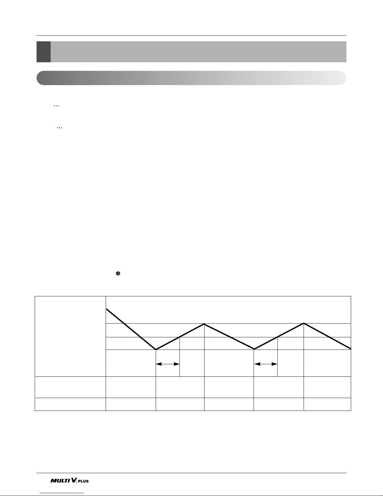
■ Cooling Mode Operation
• When selecting the Cooling( ) Mode Operation, the unit will operate according to the setting by the remote con-
troller and the operation diagram is as follows.
Intake Air Temperature
SET TEMPERATURE +0.5°C
(COMP. ON)
SET TEMPERATURE
SET TEMPERATURE -0.5°C
(COMP. OFF)
Selected Selected Selected
fan speed fan speed fan speed
COMPRESSOR ON OFF ON OFF ON
INDOOR FAN Low Low
More than
3 minutes
More than
3 minutes
(1) The function of main control
Service Manual 29
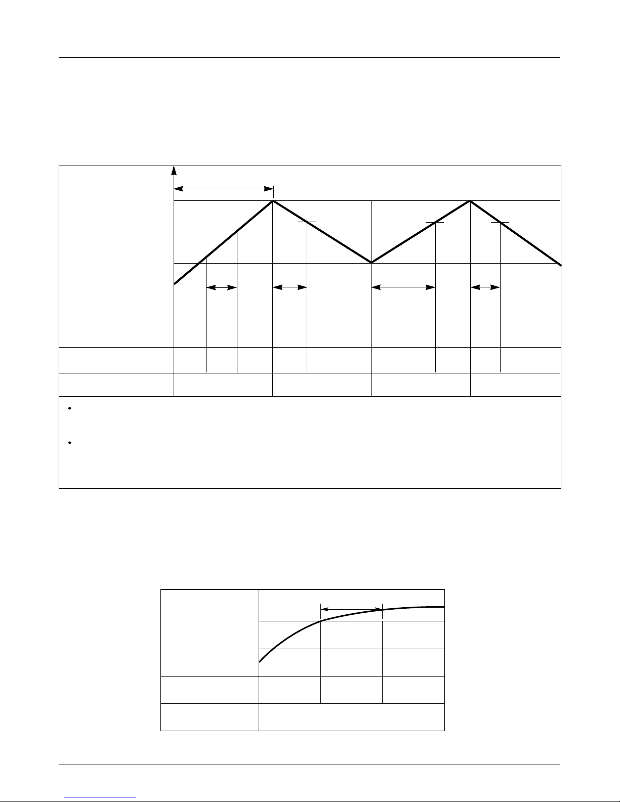
Operation Details
Intake Air Temperature.
Setting Temperature .+3°C
(Compressor OFF)
Setting Temperature
(Compressor ON)
INDOOR FAN
COMPRESSOR ON OFF ON OFF
A point; While the indoor Heat-Exchanger temperature is higher than 40°C fan operates at low speed,
when it becomes lower than 40˚C fan stops.
B point; When the indoor Heat-Exchanger temperature is higher than 42°C, fan operates at selected fan
speed, when it becomes lower than 39°C, the fan operates at low speed.
■ Heating Mode Operation
The unit will operate according to the setting by the remote controller and the operation diagram is shown as follows.
(Hot Start)
Low
OFF
Selected
Fan Speed
minimum 3min
Selecting fan
speed
LowLowLow OFF OFF
minimum
10sec.
1min
A
A
minimum
1min.
minimum
10sec.
B
■ Hot-Start Control
• The indoor fan sdoes not rotate until the evaporator piping temperature reaches to 25°C.
• If the evaporator piping temperature drops below 22°C, indoor fan stops again.
• The operation diagram is as follows.
PIPING
TEMPERATURE
1min
COMPRESSOR
INDOOR FAN
ON
OFF LOW
Selected
fan speed
22°C
25°C
30 Indoor Unit
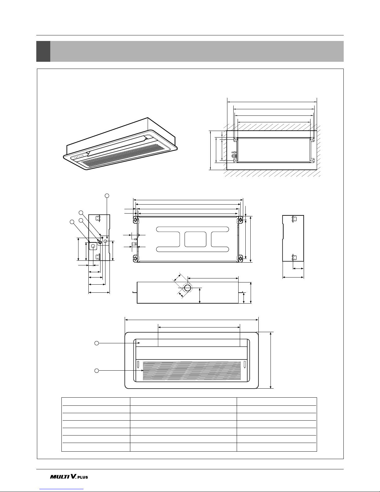
4. Dimensional Drawings
Dimensional Drawings
LRNV076TCA(C)0/LRNN076TCA(C)0/LRNV072TCA(C)0/LRNN072TCA(C)0
LRNV096TCA(C)0/LRNN096TCA(C)0/LRNV092TCA(C)0/LRNN092TCA(C)0
LRNV126TCA(C)0/LRNN126TCA(C)0/LRNV122TCA(C)0/LRNN122TCA(C)0
694.5
1050
480
846
860
328.430.8
390
893.4
931.6
16.7
50
42.7
7
155
97.7
37
116.3
141.8
180
164
194.4
91.6
180
430
130
Ø80
Ø55
180
91.6
1,000 (Ceiling opening)
931.6
893.4 (Hanging bolt)
328.4 (Hanging bolt)
860
390
30.8
430 (Ceiling opening)
4
5
6
3
2
1
(unit : mm)
Number Name Descripition
1 Liquid pipe connection ø6.35 flare
2 Gas pipe connection ø12.7 flare
3 Drain pipe connection
4 Power supply connection
5 Air discharge grill
6 Air suction grill
 Loading...