

Page 1

삼 흥
정 판
Microwave Oven
Service Manual
JVM1790BK/CK/SK/WK
CAUTION
BEFORE SERVICING THE UNIT, READ THE
SAFETY PRECAUTIONS IN THIS MANUAL.
Page 2

CAUTION
SAFETY PRECAUTIONS
PRECAUTIONS TO BE OBSERVED BEFORE AND
DURING SERVICING TO AVOID POSSIBLE EXPOSURE
TO EXCESSIVE MICROWAVE ENERGY
a. Do not operate or allow the oven to be operated with the door open.
b. Make the following safety checks on all ovens to be serviced before activating the
magnetron or other microwave source, and make repairs as necessary; (1) Interlock
operation, (2) proper door closing, (3) seal and sealing surfaces (arcing, wear, and
other damage), (4) damage to or loosening of hinges and latches, (5) evidence of
dropping or abuse.
c. Before turning on microwave power for any service test or inspection within the
microwave generating compartments, check the magnetron, wave guide or
transmission line, and cavity for proper alignment, integrity, and connections.
d. Any defective or misadjusted components in the interlock, monitor, door seal, and
microwave generation and transmission systems shall be repaired, replaced, or
adjusted by procedures described in this manual before the oven is released to the
owner.
e. A Microwave leakage check to verify compliance with the Federal performance standard should
be performed on each oven prior to release to the owner.
• Proper operation of the microwave ovens requires that the magnetron be assembled to the
wave guide and cavity. Never operate the magnetron unless it is properly installed.
• Be sure that the magnetron gasket is properly installed around the dome of the tube whenever
installing the magnetron.
• Routine service safety procedures should be exercised at all times.
• Untrained personnel should not attempt service without a thorough review of the test
procedures and safety information contained in this manual.
Page 3

FOREWORD
Read this Manual carefully. Failure to adhere to or observe the information in this Manual may result in exposing
yourself to the Microwave Energy normally contained within the oven cavity.
TABLE OF CONTENTS
(Page)
SAFETY PRECAUTIONS
SPECIFICATIONS
CAUTIONS
INSTALLATIONS
OPERATING INSTRUCTIONS
CONTROL PANEL
CONTROL PANEL INSTRUCTIONS
OVERALL CIRCUIT DIAGRAM
SCHEMATIC DIAGRAM
MATRIX CIRCUIT FOR TOUCH KEY BOARD
GENERAL INFORMATION FOR SERVICE
GENERAL PRECAUTIONS IN USE
TRIAL OPERATION
FEATURES AND SPECIFICATIONS FEATURES
SERVICE INFORMATION
PRECAUTIONS AND REPAIR SERVICE TIPS
MICROWAVE LEAKAGE TEST
------------------------------------------------------------------------------------------------------------------------------------------
----------------------------------------------------------------------------------------------------------------------------------
----------------------------------------------------------------------------------------------------
--------------------------------------------------------------------------------------------------------------------------------
----------------------------------------------------------------------------------------------------------------
-------------------------------------------------------------------------------------------------------------------------
------------------------------------------------------------------------------------------------
---------------------------------------------------------------------------------------------------------------
-----------------------------------------------------------------------------------------------------------------
-----------------------------------------------------------------------------------------------
-------------------------------------------------------------------------------------------------
-----------------------------------------------------------------------------------------------------------------------
----------------------------------------------------------------------------------------------------------------------
-------------------------------------------------------------------------------------------------------
Inside front page
1-1
2-1
3-1
4-1
4-1
4-2
5-1
5-1
-----------------------------------------------------------------------------------
-------------------------------------------------------------------------------
-----------------------------------------------------------------------------------
5-2
6-1
6-1
6-1
6-1
7-1
7-1
7-2
POWER OUTPUT MEASUREMENT
DISASSEMBLY INSTRUCTIONS
INTERLOCK SYSTEM
INTERLOCK CONTINUITY TEST
TEST AND CHECKOUT PROCEDURES AND TROUBLE SHOOTING
A. TEST PROCEDURES
B. CHECKOUT PROCEDURES
C. TROUBLE SHOOTING
EXPLODED VIEW
PART REFERENCE LIST
SCHEMATIC DIAGRAM OF PCB
PRINTED CIRCUIT BOARD
PCB PARTS LIST
--------------------------------------------------------------------------------------------------------------------------------
-------------------------------------------------------------------------------------------------------------------------------
------------------------------------------------------------------------------------------------------------------
----------------------------------------------------------------------------------------------------------------------
----------------------------------------------------------------------------------------------------------
------------------------------------------------------------------------------------------------
-----------------------------------------------------------------------------------------------------
---------------------------------------------------------------------------------------------------
--------------------------------------------------------------------------------------------------------
----------------------------------------------------------------------------------------------
------------------------------------------------------------------------------------------------------
----------------------------------------------------------------------------------------------------
7-3
7-4
7-12
7-14
-------------------------------------------------
7-15
7-15
7-19
7-24
8-1
9-1
10-1
10-2
11-1
Page 4

SPECIFICATIONS
Rated Power Consumption
Microwave Output
Frequency
Power Supply
Rated Current
Magnetron Cooling
Rectification
Door Sealing
Safety Devices
Magnetron
High Voltage Capacitor
High Voltage Diode
Cook top Lamp
Cavity Lamp
Timer
Tray
Overall Dimensions
Effective Capacity of Oven Cavity
Accessories
---------------------------------------------------------------
-----------------------------------------------------------------
------------------------------------------------
---------------------------------------------------------
---------------------------------------------------
---------------------------------------------------
--------------------------------------------
------------------------------------------------------
-----------------------------------------------------
--------------------------------------------------
--------------------------------------------------------
-------------------------------------------------
-----------------------------------------------------
------------------------------------------------------
----------------------------------
--------------------------------------
-------------------------------------------
-------------------------------------------
-----------------------
1600W (Microwave oven only) 1650W (Convection only)
1000W (IEC60705)
Adjustable 100W through 1000W, 10 steps
2450 MHz ± 50 MHz
120 VAC, 60 Hz
13.5 Amp. (Microwave oven+Cook top lamp+Ventilation fan)
Forced Air Cooling
Rectification Voltage Double Half-Wave
Choke System
Magnetron Thermal Fuse:
Open at 150°C ± 6°C
Oven Cavity Thermostat:
Open at 145°C ± 6°C
Fuse(20A)
Primary Interlock Switch
Secondary Interlock Switch
Interlock Monitor
2M246-21CT
Capacitor: 0.95µF, 2.1 KV AC
Diode; 350mA, 9.0 KV
130 V, 50 W
130 V, 35 W
Digital, up to 95 mim. 00 sec. (in each cooking stage)
Tempered Safety Glass
2915/16"(W)x167/16"(H)x153/8"(D)
1.7 Cu.ft.
Owner’s Manual & Cooking Guide, Installation Manual,
Exhaust Adapter, Exhaust Damper, Mounting Kit and Two
Filters, Rotating Ring Assembly, Metal Racks.
1-1
Page 5
CAUTIONS
Unlike other appliances, the microwave oven is
high-voltage and high-current equipment.
Though it is free from danger in ordinary use,
extreme care should be taken during repair.
• DO NOT operate on a 2-wire extension cord during
repair and use.
• NEVER TOUCH any oven components or wiring during
operation.
• BEFORE TOUCHING any parts of the oven, always
remove the power plug from the outlet.
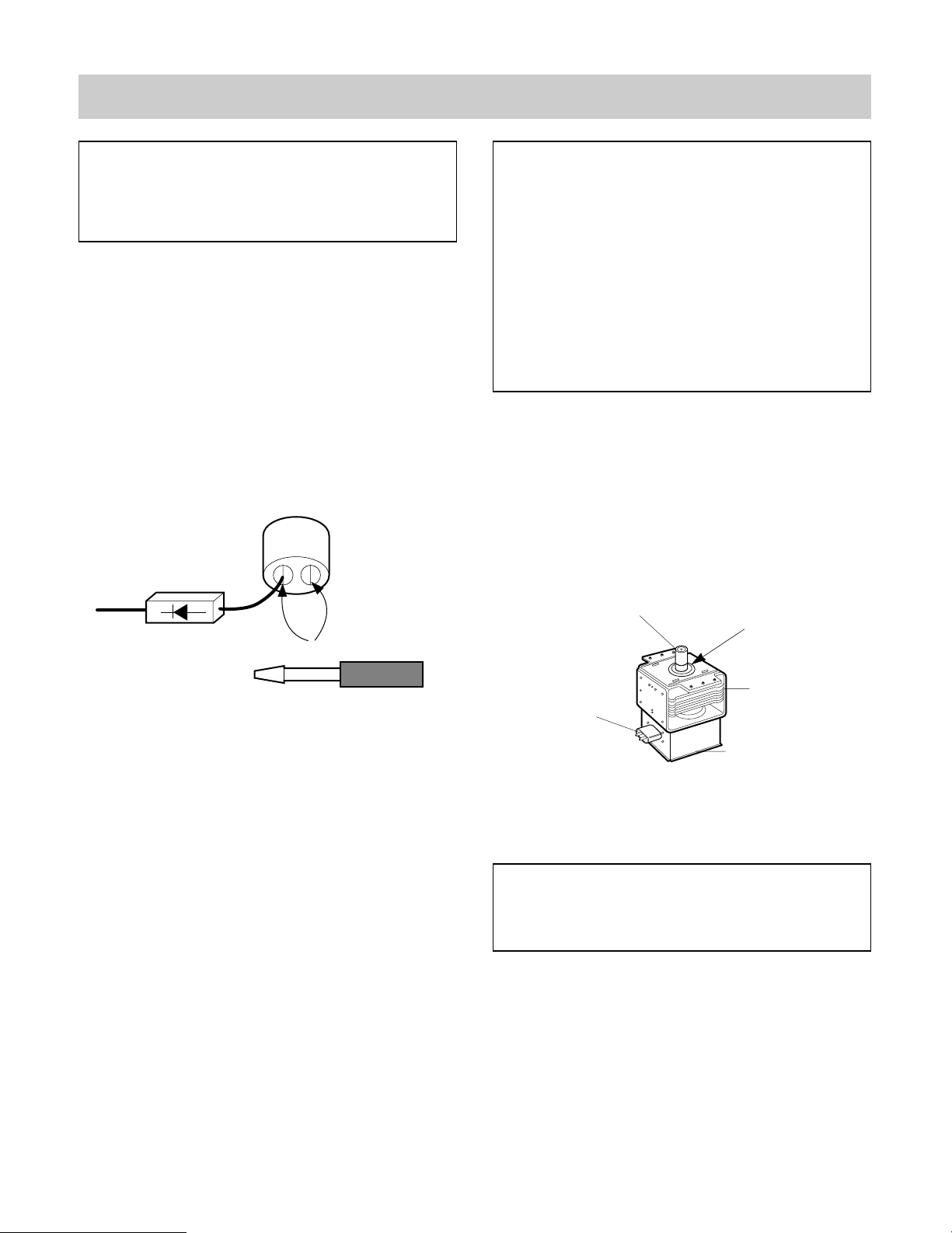
• For about 30 seconds after the oven stops, an electric
charge remains in the high voltage capacitor. When
replacing or checking, you must discharge the high
voltage capacitor by shorting across the two terminals
with an insulated screwdriver.
MICROWAVE RADIATION
Personnel should not be exposed to the
microwave energy which may radiate from the
magnetron or other microwave generating
device if it is improperly used or connection.
All input and output microwave connections,
waveguide, flange, and gasket must be secure
never operate the device without a microwave
energy absorbing load attached.
Never look into an open waveguide or antenna
while the device is energized.
• Proper operation of the microwave oven requires that
the magnetron be assembled to the waveguide and
cavity. Never operate the magnetron unless it is
properly installed.
• Be sure that the magnetron gasket is properly
installed around the dome of the tube whenever
installing the magnetron.
• Remove your watches whenever working close to or
replacing the Magnetron.
• DO NOT touch any parts of the control panel circuit. A
resulting static electric discharge may damage this
P.C.B.
• NEVER operate the oven with no load.
• NEVER injure the door seal and front plate of the oven
cavity.
• NEVER put iron tools on the magnetron.
• NEVER put anything into the latch hole and the interlock
switches area.
ANTENNA
Gasket
COOLING FIN
FILAMENT
TERMINALS
MAGNETRON
CHASSIS GROUND
MAGNETRON
THE OVEN IS TO BE SERVICED ONLY
BY PROPERLY QUALIFIED SERVICE
PERSONNEL.
2-1
Page 6
INSTALLATIONS
BEFORE YOU BEGIN, READ THE FOLLOWING INSTRUCTIONS COMPLETELY AND CAREFULLY.
PRECAUTIONS ON INSTALLATION
A. Plug the power supply cord into a 120V AC, 60Hz,
single-phase power source with a capacity of 15A
or 20A.
B. Avoid placing the unit in a location where there is
direct heat or splashing water.
C. Install the unit on the mounting plate firmly.
D. Place the unit as far away as possible from TV,
radio, etc. to prevent interference.
GROUNDING INSTRUCTIONS
For personal safety, this appliance must be fully
grounded at all times.
In the event of an electrical short circuit, grounding
reduces the risk of electrical shock.
The plug must be plugged into an outlet that is
properly installed and grounded.
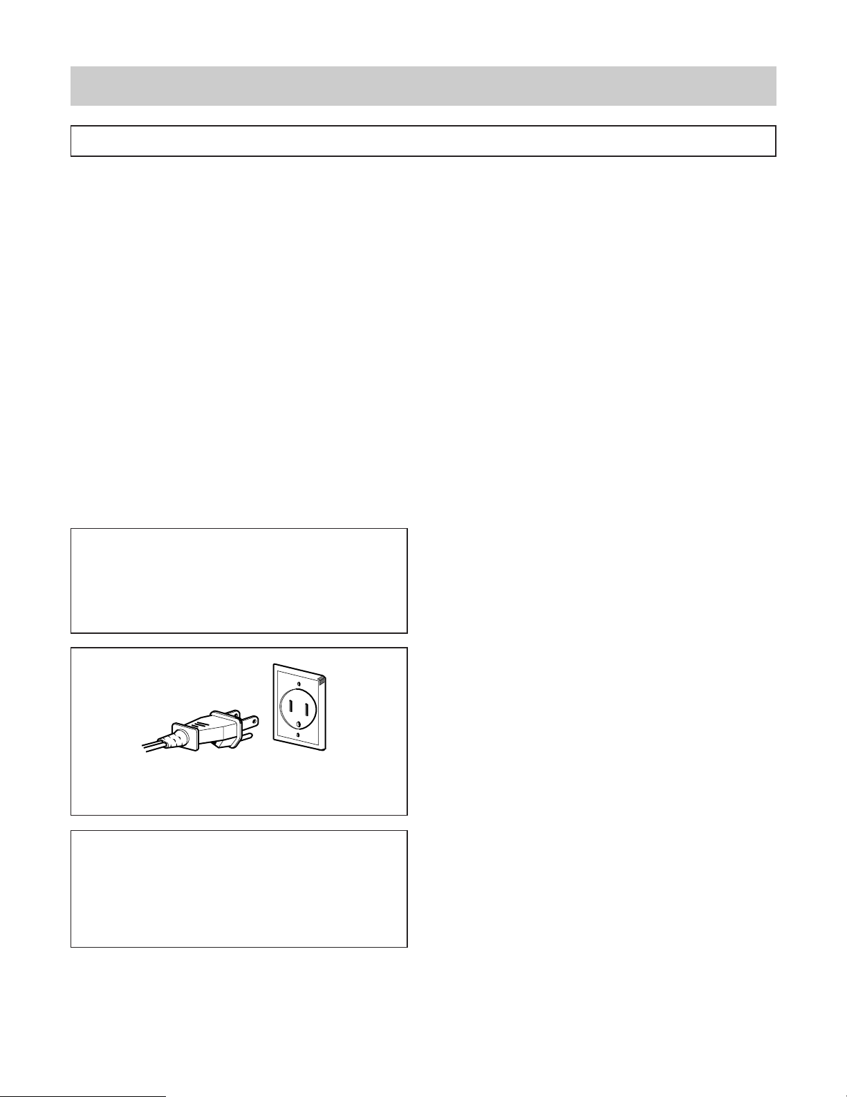
CAUTION
This unit is equipped with a 3-prong plug for your
safety. If the wall outlet is a grounded 3-hole type,
the unit will be grounded automatically.
Plug with Ground
Prong
Properly Polarized
and Grounded
Outlet
WARNING
Improper use of the grounding plug can result in a
risk of electric shock.
Do not, under any circumstances, cut or remove the
third ground prong from the power cord plug.
3-1
Page 7
CONTROL PANEL
OPERATING INSTRUCTIONS
For Model: JVM1790BK
JVM1790CK
JVM1790SK
JVM1790WK
4-1
Page 8

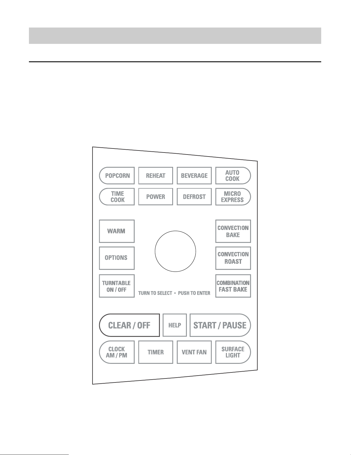
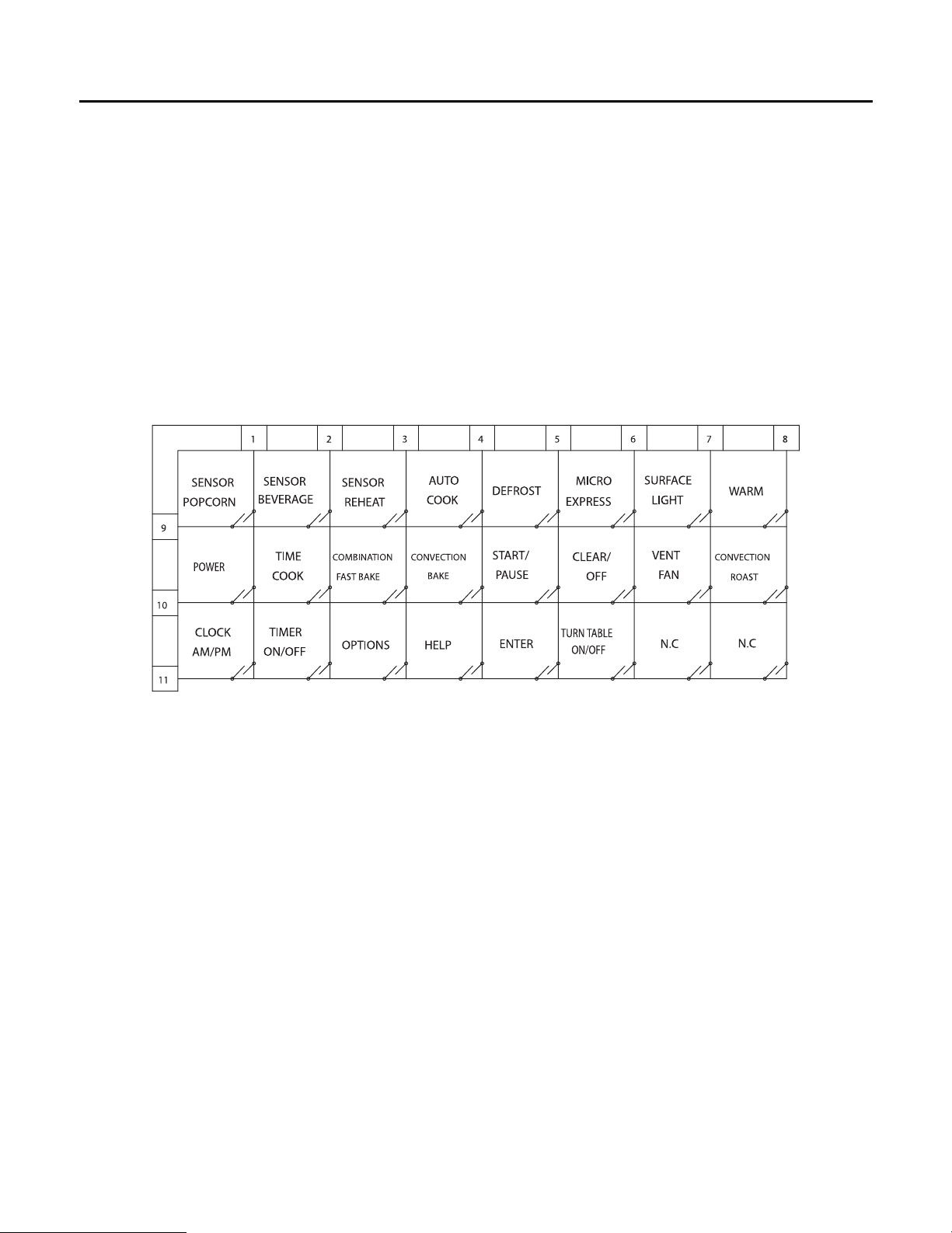
CONTROL PANEL INSTRUCTIONS
1. TIME COOK: Touch this pad when setting Microwave
cooking.
2. CONVECTION BAKE: Touch this pad when setting
Convection bake cooking.
3. CONVECTION ROAST: Touch this pad when setting
Convection roast cooking.
4. COMBINATION FAST BAKE: Touch this pad when setting
Combination cooking.
5. POPCORN: Touch this pad when popping
popcorn in your microwave oven. The oven’s sensor
will tell the oven how long to cook depending on the
amount of humidity it detects from the popcorn.
6. AUTO COOK: Touch this pad to cook chicken pieces, fish,
ground meat, potatoes, canned vegetables, fresh
vegetables, frozen vegetables. The oven’s
sensor will tell the oven how long to cook depending
on the amount of humidity coming from the food.
7. REHEAT: Touch this pad to reheat leftovers.
The oven’s sensor will tell the oven how long to
cook depending on the amount of humidity coming
from the food.
8. WARM: Touch this pad to warm.
10. TIMER: Touch this pad to set the timer.
11. CLOCK AM/FM: Touch this pad to enter the time of day.
12. OPTION: Touch this pad to change the oven’s default
settings.
13. POWER: Touch this pad to select a cooking power
level.
14. CLEAR/OFF: Touch this pad to stop the oven or
to clear all entries.
15. START/PAUSE: Touch this pad to start a function
or enter all entries. If you open the door after oven
begins to cook, touch START/PAUSE again.
16. TURNTABLE ON/OFF: Touch this pad to turn off
the turntable. OFF will appear in the display.
17. SURFACE LIGHT: Touch this pad to turn on the
cooktop/countertop light.
18. VENT FAN: Touch this pad to turn the fan
on/off.
9. DEFROST: Touch this pad to select food
type and defrost food by weight.
4-2
Page 9
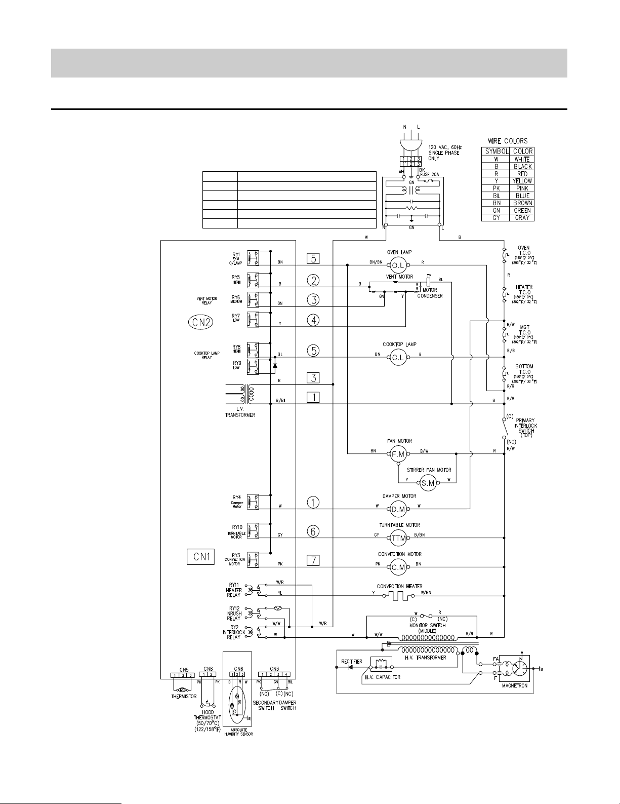
OVERALL CIRCUIT DIAGRAM
ERROR MODEDISPLAY
F1
F2
F3
F4
F5
THERMAL SENSOR OPEN
THERMAL SENSOR SHORT
KEYPANEL SHORTED FOR > 60 SECONDS
HUMIDITY SENSOR OPEN
HUMIDITY SENSOR SHORT
SCHEMATIC DIAGRAM
For Model: JVM1790BK
JVM1790CK
JVM1790SK
JVM1790WK
5-1
Page 10
MATRIX CIRCUIT FOR TOUCH KEY BOARD
For Model: JVM1790BK / JVM1790CK
JVM1790SK / JVM1790WK
5-2
Page 11

GENERAL INFORMATION FOR SERVICE
GENERAL PRECAUTIONS IN USE
A. Never operate the unit when it is empty.
Operating the oven with no load may shorten the
life of the magnetron. Whenever cooking dry foods
(dried fish, bread, etc.) or a small amount of food,
be sure to put a glass of water into the cooking
compartment. The glass turntable may become hot
after operating, be careful when touching it.
B. Aluminum foil should be avoided because it will
disrupt cooking and may cause arcing. However,
small pieces may be used to cover some parts of
food to slow the cooking. Any aluminum foil used
should never be closer than 2.5 cm to any side wall
of the oven.
TRIAL OPERATION
After installation, the following sequences and results
should be checked carefully.
A. Put a container filled with water (about 1 liter) into
the oven, and close the door tightly.
B. Set cooking time for 10 minutes by touching “1”
and then “0” three times. “1, 0, 0, 0” appears in
the display window.
C. Touch the START key.
Make sure the cavity light comes on. The unit will
begin cooking and the display window will show the
time counting down by seconds.
D. After about 5 minutes, make sure the primary
interlock switch, the secondary interlock switch and
the interlock monitor switch operate properly by
opening and closing the door several times. Touch
the START key each time the door is closed.
E. Continue operating the unit. Four long beep sound
signal is heard when the time is up. The unit will
shut off automatically.
F. Confirm the water is hot.
G. Finally, measure the output power according to
“POWER OUTPUT MEASUREMENT” on
page 7-3.
FEATURES AND SPECIFICATIONS
FEATURES
A. The safety systems incorporated in this model are:
(1) Primary interlock switch
(2) Secondary interlock switch
(3) Interlock monitor switch
(4) Choke system
(5) Magnetron thermostat
(6) Oven cavity thermostat
(Note: This thermostat located on the oven
cavity will open and stop the unit from operation
only if a high temperature is reached, such as,
a fire created by overcooking food.)
B. Any one of 10 power output levels ranging 100W to
1000W can be selected by the touch control and
electronic computer system.
STANDARD TEST LOAD
The standard test load is one liter (1000ml.) water with
starting temperature of 59°F ~ 75°F in a 1000ml
beaker.
(DO NOT USE ANY OTHER LOAD OR DISH AS
RESULTS WILL VARY FROM STANDARD.)
PERFORMANCE TEST FOR MICROWAVE
1. Use Glass Tray and the beaker WB64 x 0073.
2. Record initial water temperature.
3. Run at high power for 2:03.
4. Record end water temperature.
The minimum difference between the initial and
ending temperature should be: 38°F @ 120V
TO PREVENT ELECTRICAL SHOCK. USE EXTREME
CAUTION WHEN DIAGNOSING OVEN WITH OUTER
CASE REMOVED AND POWER “ON”. THE HIGH
VOLTAGE SECTION OF THE POWER SUPPLY
INCLUDING FILAMENT LEADS IS 4000 VOLTS
POTENTIAL WITH RESPECT TO GROUND.
6-1
Page 12

SERVICE INFORMATION
PRECAUTIONS AND REPAIR SERVICE TIPS
PRELIMINARY
A. SINCE NEARLY 2,100 VOLTS EXISTS IN SOME
CIRCUITS OF THIS UNIT REPAIRS SHOULD BE
CARRIED OUT WITH GREAT CARE.
The filament leads of magnetron carry High
Voltage with respect to ground. Extreme caution
must be exercised. Never plug the unit into a
power source to determine which component is
defective in high voltage section.
B. TO AVOID POSSIBLE EXPOSURE TO
MICROWAVE ENERGY LEAKAGE, THE
FOLLOWING PRECAUTIONS MUST BE TAKEN
BEFORE SERVICING.
(1) Before the power is applied:
(a) Make sure the primary interlock switch, the
secondary interlock switch and the interlock
monitor switch operate properly by opening
and closing the door several by opening and
closing the door several times.
(b) Make sure the perforated screen and the
dielectric choke of the door are correctly and
firmly mounted.
(2) After power is applied:
(a) Make sure the interlock switch mechanism
is operating properly by opening and closing
the door.
(b) Check microwave energy leakage must
be below
the limit of 5 mW/cm2.
(All service adjustments should be made for
minimum microwave energy leakage
readings).
(3) Do not operate the unit until it is completely
repaired, if any of the following conditions exist.
The unit must not be operated.
(a) The door does not close firmly.
(b) The hinge is broken.
(c) The door seal is damaged.
(d) The door is bent or warped, or there is any
other visible damage on the unit that may
cause microwave energy leakage.
NOTE: Always keep the seal clean.
(e) Make sure that there are no defective parts
in the interlock mechanism.
(f) Make sure that there are no detective parts
in the microwave generating and transmission
assembly (especially waveguide).
(4) The following items should be checked after the
unit is repaired:
(a) The interlock monitor switch is connected
correctly and firmly.
(b) The magnetron gasket is properly positioned
and mounted.
(c) The waveguide and the oven cavity are intact.
(no microwave energy leakage)
(d) The door can be properly closed and the
safety switches work properly.
(e) The unit must stop when the door is opened or
the time is up.
The unit must not be operated with any of the above
components removed or by-passed.
7-1
Page 13
MICROWAVE LEAKAGE TEST
CAUTIONS
• Be sure to check microwave leakage prior to
servicing the oven if the oven is operative prior to
servicing.
• The service personnel should inform the
manufacture importer, or assembler of any certified
oven unit found to have a microwave emission level
in excess of 5 mW/cm2and should repair any unit
found to have excessive emission levels at no cost to
the owner and should ascertain the cause of the
excessive leakage. The service personnel should
instruct the owner not to use the unit until the oven has
been brought into compliance.
• If the oven operates with the door open, the service
personnel should:
- Tell the user not to operate the oven.
• The service personnel should check all surface and
vent openings for microwave leakage.
• Check for microwave leakage after every servicing. The
power density of the microwave radiation leakage
emitted by the microwave oven should not exceed
4 mW/cm2. Always start measuring of an unknown field
to assure safety for operating personnel from radiation
leakage.
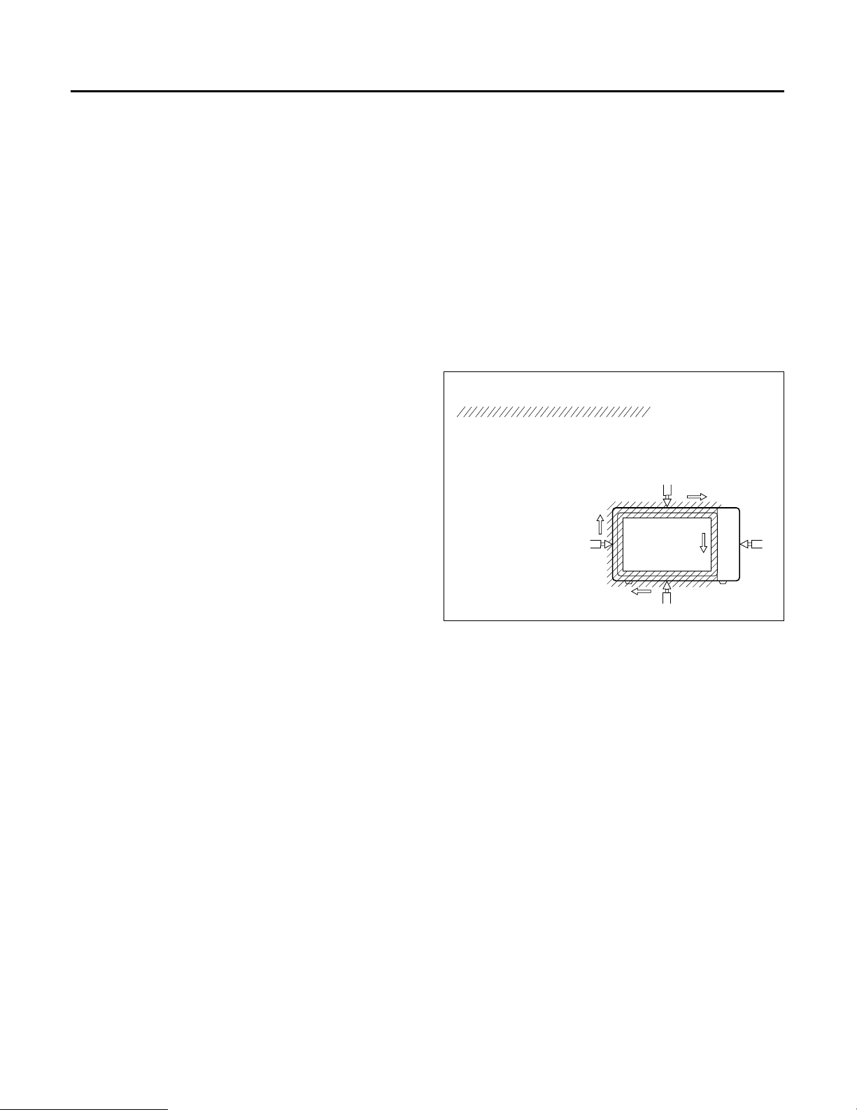
MEASURING MICROWAVE ENERGY
LEAKAGE
• Pour 275±15cc of 20±5°C(68±9°F) water in a beaker
which is graduated to 600 cc, and place the beaker
on the center of the turntable.
• Set the energy leakage monitor to 2,450 MHz and
use it following the manufacturer's recommended
test procedure to assure correct result.
• When measuring the leakage, always use the 2-inch
(5cm) spacer supplied with the probe.
• Operate the oven at its maximum output.
• Measure the microwave radiation using and
electromagnetic radiation monitor by holding the
probe perpendicular to the surface being measured.
Move probe along shaded area.
Probe scanning speed
Less than 2.5 cm/sec. ( 1 in/sec)
EQUIPMENT
•
TESTER (VOLTS-DC, AC, Ohmmeter)
• Microwave survey meter
- Holaday HI-1500
HI-1501
- Narda 8100
8200
• 600 cc non conductive material beaker (glass or
plastic), inside diameter: approx. 8.5 cm (31/2in.)
• Glass thermometer: 100°C or 212°F (1 deg scale)
• It should not exceed 4 mW/cm2.
7-2
Page 14

MEASUREMENT WITH THE OUTER CASE
REMOVED
(1) When you replace the magnetron, measure for
microwave energy leakage before the outer case
is installed and after all necessary components
are replaced or adjusted. Special care should be
taken in measuring the following parts.
- Around the magnetron
- The waveguide
WARNING: AVOID CONTACTING ANY HIGH
VOLTAGE PARTS.
MEASUREMENT WITH A FULLY
ASSEMBLED OVEN
(1) After all components, including the outer
panels, are fully assembled, measure for
microwave energy leakage around the door
viewing window, the exhaust opening and air
inlet openings.
(2) Microwave energy leakage must not exceed the
values prescribed below.
NOTES:
Leakage with the outer panels removed - less
than 5 mW/cm2.
Leakage for a fully assembled oven (“Before the
latch switch (primary) is interrupted”) with the door
in a slightly opened position - less than 2 mW/cm2.
NOTE WHEN MEASURING
(1) Do not exceed meter full scale deflection.
(2) The test probe must be removed no faster than
1 inch/sec (2.5cm/sec) along the shaded area,
otherwise a false reading may result.
(3) The test probe must be held with the grip portion
of the handle. A false reading may result if the
operator’s hand is between the handle and the
probe.
(4) When testing near a corner of the door, keep
the probe perpendicular to the surface making
sure the probe horizontally along the oven
surface, this may possibly cause probe damage.
RECORD KEEPING AND NOTIFICATION
AFTER MEASUREMENT
(1) After adjustment and repair of any microwave
energy interruption or microwave energy blocking
device, record the measured values for future
reference. Also enter the information on the
service invoice.
(2) Should the microwave energy leakage not be
more than 2 mW/cm2after determining that all
parts are in good condition, functioning properly
and genuine replacement parts which are listed in
this manual have been used.
(3) At least once a year, have the electromagnetic
energy leakage monitor checked for calibration
by its manufacturer.
7-3
Page 15
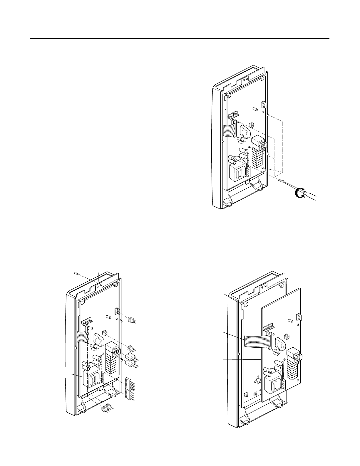
DISASSEMBLY INSTRUCTIONS
Figure 1
Control Panel
Screw
Power
Transformer
(CN2)
(CN1)
(Relay 2)
(CN6)
(Relay 11)
(CN5)
(CN3)
(CN8)
Circuit Board
Figure 2
FPC Connector(S1)
Control Bracket
Circuit Board
Figure 3
IMPORTANT NOTES:
UNIT MUST BE DISCONNECTED FROM ELECTRICAL OUTLET WHEN MAKING REPAIRS, REPLACEMENTS, ADJUSTMENTS AND CONTINUITY CHECKS. WAIT AT LEAST ONE MINUTE,
UNTIL THE HIGH VOLTAGE CAPACITOR IN THE
HIGH VOLTAGE POWER SUPPLY HAS FULLY
DISCHARGED.
THE CAPACITOR SHOULD BE DISCHARGED BY
USING INSULATED WIRE - I.E. TEST PROBE
CONNECTED TO 10K-OHM RESISTOR IN SERIES
TO GROUND.
WHEN RECONNECTING THE WIRE LEADS TO
ANY PART, MAKE SURE THE WIRING CONNECTIONS AND LEAD COLORS ARE CORRECTLY
MATCHED ACCORDING TO THE OVERALL CIRCUIT DIAGRAM. (ESPECIALLY SWITCHES AND
HIGH VOLTAGE CIRCUIT.)
A. REMOVING POWER AND CONTROL
CIRCUIT BOARD (Figures 1, 2 and 3)
(1) Disconnect power at the main fuse or circuit
breaken, or pull the plug. Remove the top grille by
removing the two screws that hold it in place.
(2) Remove a screw securing the control panel
assembly to the oven cavity.
(3) Remove the control panel with pushing it upward.
(4) Remove the six connectors (CN1, CN2, CN3, CN5,
CN6, CN8) and wire leads (Relay2, Relay11) from
the circuit board.
(5) Remove 7 screws securing the circuit board.
(6) Remove the FPC connector from the terminal
socket following “HOW TO REMOVE THE FPC
CONNECTOR” on the next page.
(7) Remove the knob.
(8) Remove the circuit board from the control bracket
carefully.
7-4
Page 16

HOW TO REMOVE THE F.P.C. CONNECTOR
HOW TO INSERT THE F.P.C. CONNECTOR
Follow the steps below as illustrated in Figures 4
and 5 to remove the F.P.C. connector.
(1) Hold the edges of the plastic fastener with
thumb and forefinger.
(Figure 4)
(2) Lift up the lever of the plastic fastener from
the terminal socket by lightly pressing the
lever end with forefinger.
(Figure 5)
(3) Remove the F.P.C. connector from the
terminal socket.
Follow the steps below as illustrated in Figures 6
and 7 to insert the F.P.C. connector.
(1) Insert the F.P.C. connector into the terminal
socket securely with the fingers.
(2) Hold the plastic fastener with thumb and
forefinger of the other hand, and push it
slowly into the terminal socket. (Figure 6)
NOTE: When reconnecting the F.P.C
connector make sure that the holes
on the F.P.C. connector are properly
engaged with the hooks on the plastic
fastener
(3) Lock the level of the plastic fastener into the
hook of the terminal socket securely by
releasing the fingers.
(Figure 7)
Figure 4
Figure 5
Figure 6
Figure 7
7-5
Page 17

B. REMOVING OVEN FROM WALL
Vent Grille
Controller
(3 screws)
Door
Mounting
Plate
(1 or 2 screws)
Out Case
Mount,All
Figure 8
(2 PERSONS REQUIRED)
Oven is hooked on metal tabs at bottom of wall
mounting plate and fastened to cabinet by (3) top
cabinet bolts.
CAUTION: Oven weights 77 lbs. Requires 2
persons for removal
1. Disconnect Power Cord, Top exhausted models
disconnect duct and remove damper assembly.
2. Remove (3) top cabinet bolts while supporting unit.
3. Lift off back hooks and pull unit forward slowly
providing adequate support to prevent dropping unit
during removal.
C. REMOVING THE OUT CASE(Figure 8)
(1) Remove the vent grille by removing two screws
securing it to the out case.
(2) Remove two screws securing it to the air duct.
(3) Remove the base plate by removing four screws
securing it to the out case. Remove the Mount,
All from the out case by removing two screws
securing it to the out case.
(4) Remove four screws from the rear section.
(5) Remove the outcase with pushing it back.
(6) Remove the outcase with disconnecting power
cord connector.
7-6
Page 18

D. REMOVING THE DOOR INTERLOCK
Latch Board
Primary
Interlock Switch
Interlock
Monitor Switch
Secondary
Interlock Switch
Latch Board
BK(CN1)
RD(Bottom TCO)
RD(H.V.Transformer)
WH(from Convection Heater)
Primary Interlock Switch
Monitor Interlock Switch
Secondary Interlock Switch
PK(from P.C.B)
GN
(
from P.C.B)
WH
(from H.V.Transformer)
RD
(from H.V.Transformer/
Figure 9
Figure 10
WIRE COLOR
SYMBOL COLOR
WH
BK
BR
RD
BL
PK
GY
GN
N.P.
WHITE
BLACK
BROWN
RED
BLUE
PINK
GREY
GREEN
Not Provided
SWITCHES (Figures 9, 10)
(1) Disconnect the wire leads from the interlock
switches.
(2) Remove two screws securing the Latch Board.
(3) Make necessary replacements and check
microwave energy leakage according to
“ADJUSTMENT PROCEDURE” on page 7-12.
7-7
Page 19

E. REMOVING MAGNETRON
Figure 11
Figure 13-a Figure 13-b
Figure 12
Vent Grille
Controller
(3 screws)
Door
Mounting
Plate
(1 or 2 screws)
Out Case
Mount,All
(Figures 11 Through 13)
(1) Remove the vent grille by loosening two screws.
(Figure 11)
(2) Remove the outcase. See Figure 13-b.
(3) Remove four tap tite screws securing the
magnetron to the wave guide.
(4) Remove the magnetron VERY CAREFULLY.
NOTES:
• When removing the magnetron, make sure that its
dome does not hit any adjacent parts, or it may be
damaged.
• When replacing the magnetron, be sure to install the
magnetron gasket in the correct position and be sure
that the gasket is in good condition.
• After replacing the magnetron, check for microwave
energy leakage with a survey meter Check
microwave energy leakage must be below the limit
of 5 mW/cm2. (All service adjustments should be
made for minimum microwave energy leakage
readings.)
7-8
Page 20

F. REMOVING STIRRER FAN
Figure 16
Figure 15
Figure 14
Door Screen
Figure 17
(Figures 14 and 15)
(1) Remove two screws securing it to the oven
upper plate by using drive screw.
(2) Rotate slightly and pull out the stirrer fan cover.
(3) Remove the stirrer fan.
G. REMOVING DOOR (Figure 16)
(1) Remove the vent grille by two screws securing it to
the outcase loosening.
(2) Lift up and draw the door.
NOTES:
• After replacing the door, be sure to check that the
primary interlock switch, the secondary interlock
switch and the interlock monitor switch is in good
operating normally.
• After replacing the door, check for microwave energy
leakage with a survey meter. Microwave energy
leakage must be below the limit of 5mW/cm2. (With a
275 ml water load)
H. DISASSEMBLING DOOR (Figure 17)
(1) Remove the dielectric choke by using knife
blade or small screw driver, etc.
(2) Remove two screws securing it to the door handle.
CAUTION: Be careful not to damage door seal
plate with the screwdriver.
7-9
Page 21

I. ASSEMBLING DOOR
Space
(1 or 2 screws)
MOUNT, ALL
Figure 18
Figure 19-a
Figure 19-b
Figure 19-c
(1) When mounting the door assembly to the oven
assembly, be sure to adjust the door assembly
parallel to the chassis. Also adjust so the door has no
play between the inner door surface and oven frame
assembly. If the door assembly is not mounted
properly, microwaves may leak from the clearance
between the door and the oven.
J. REMOVING THE VENTILATION MOTOR
(1) Disconnect Power Cord, Top exhausted models
disconnect duct and remove damper assembly.
(2) Remove top cabinet bolts while supporting unit.
(3) Lift off back hooks and pull unit forward slowly
providing adequate support to prevent dropping unit
during removal.
(4) Remove MOUNT ALL loosening one screw
loosening one screw securing the ventilation Motor
and back plate. (See Figure 19-a)
(5) Carefully pull the ventilation motor ASS'Y out of
the microwave oven. (See Figure 19-b)
K. REPLACING THE HUMIDITY SENSOR
(For sensor model only)
(1) Remove the sensor by removing two screws
securing it to the air duct. (See Figure 19-c)
(2) Mount the new humidity sensor to the air duct.
7-10
Page 22

L. REMOVING THE TURNTABLE MOTOR
Wire Leads
Turntable Motor
Figure 22-b
Figure 20
Figure 21-a
Figure 23
(1) Remove the turntable.
(2) Remove the turntable shaft VERY CAREFULLY
with a slotted screwdriver. (Figure 21)
(3) Remove the base plate by removing 7 screws
securing it to the oven cavity. (Figure 22-a)
(4) Disconnect the leadwire from the turntable motor
terminals.
(5) Remove the 2 screws securing the turntable motor
to the oven cavity ASS'Y. (Figure 22-b)
M. REMOVING CONVECTION HEATER,
THERMISTOR AND DAMPER MOTOR
(Figure 23)
(1) Remove the outer case.
(2) Remove the air duct by removing six screws
securing it to the oven front plate, guide air and
glasswool-L cover.
(3) Disconnect the wire leads of air duct.
(4) Remove the magnetron.
(5) Remove the latch board assembly.
(6) Remove the bottom plate by removing four screws.
(7) Remove the four net screws securing chamber
assembly.
(8) Lift the chamber assembly from the oven cavity.
(9) Remove three screws securing the heater of the
chamber assembly.
(10) Lift the convection heater from the chamber
assembly.
(11) Lift the damper motor from the chamber
assembly.
NOTES:
• Remove the leadwire from the turntable motor
VERY CAREFULLY.
• Be sure to grasp the connector not the wires when
removing.
• Warp the blade with tape to avoid scratching the
cavity.
7-11
Page 23

INTERLOCK SYSTEM
LATCH
LATCH BOARD
0-1/64"
0-1/64"
Latch Board
Primary
Interlock Switch
Monitor Switch
Interlock
Secondary
Interlock Switch
Figure 24-a
Figure 24-b
INTERLOCK MECHANISM
The door lock mechanism is a device which has been specially designed to eliminate completely microwave
activity when the door is opened during cooking and thus to prevent the danger resulting from the microwave
leakage.
ADJUSTMENT PROCEDURES
To avoid possible exposure to microwave energy
leakage, adjust the door latches and interlock
switches, using the following procedure.
The Interlock Monitor and Secondary Interlock Switch
act as the final safety switch protecting the user from
microwave energy. The terminals between “COM” and
“NC” of the Interlock Monitor must close when the door
is opened. After adjusting the Interlock Monitor Switch,
make sure that it is correctly connected.
Mounting of the primary/monitor/secondary switches to
the latch board.
CHECK THE DOOR LATCH AND SWITCH
CLOSING.
NOTE:
The outer cover of the microwave oven is
removed.
(1) Set the microwave oven on its side so that you can
see the latch board and the switches, as shown in
Figure 24-a.
(2) Close the door tightly and check gaps A and B to
be sure they are no more than 1/64" (0.5 mm).
See Figure 23 for close-up view of gaps A and B
(door latches). If all gaps are less than 1/64"
(0.5 mm), adjustment of the latch board may not
be necessary. Go to Steps 5 and 6 to check the
sequence of the switches.
NOTE:
To correct sequence of the Primary Interlock
Switch, Secondary Interlock Switch and the
Interlock Monitor Switch is very important.
If any gap is larger than 1/64" (0.5 mm), you will
need to adjust the latch board”. Go to step 3
and follow all steps in order.
ADJUST THE LATCH AND SWITCH CLOSING
(3) Loosen the two screws holding the plastic latch
board as shown.
(4) With the oven door closed tightly, move the latch
board upward toward the top of the oven and/or
away from the door latch until the gaps are less
than 1/64" (0.5 mm).
Hold the latch board tightly in this position until you
check the sequence of the switches in steps 5
and 6.
7-12
Page 24

TEST THE LATCH AND SWITCH SEQUENCE
(5) Open the oven door slowly. Watch the door latch,
the Secondary Switch. Release Rod and Lever
on the switches to make sure they are zero to the
body of the switches in the following sequence:
- Primary Interlock Switch
- Secondary Interlock Switch
- Interlock Monitor Switch
Adjust the latch board until the switches operate in
this sequence. See Steps 3 and 4.
(6) Close the oven door slowly and be sure it is tightly
closed. Watch the three switches to make sure
they are zero to the body of the switches in the
following sequence:
- Interlock Monitor Switch
- Secondary Interlock Switch
- Primary Interlock Switch
NOTE: The Interlock Monitor Switch is an added
safety check on the Primary and
Secondary Interlock Switches. If the
Primary and Secondary Interlock Switches
allow the oven to operate with the door
open, the Monitor Switch will blow the
fuse.
(7) When you achieve the proper sequence of
switches in Steps 5 and 6, tighten the latch board
screws at that point.
TEST THE MICROWAVE ENERGY LEAKAGE
Make sure the microwave energy leakage is below the
limit of 1mW/cm2(with a 275 ml water load) and
5mW/cm2(with a 275 ml water load without the
cabinet) when measured with a survey meter.
7-13
Page 25

INTERLOCK CONTINUITY TEST
A. PRIMARY INTERLOCK SWITCH TEST
When the door is opened slowly, an audible click
should be heard at the same time or successively
at intervals and the latches should activate the
switches with an audible click.
If the latches do not activate the switches when the
door is closed, the switches should be a adjusted
in accordance with the adjustment procedure.
Disconnect the wire lead from the primary switch.
Connect the ohmmeter leads to the common
(COM) and normally open (NO) terminal of the
switch. The meter should indicate an open circuit
in the door open condition.
When the door is closed, the meter should indicate
a closed circuit.
When the primary switch operation is abnormal,
make the necessary adjustment or replace the
switch only with the same type of switch.
B. SECONDARY INTERLOCK SWITCH TEST
Disconnect the wire lead from the secondary
switch.
Connect the ohmmeter leads to the common
(COM) and normally open (NO) terminals of the
switch. The meter should indicate a open circuit in
the door open condition. When the door is closed,
meter should indicate an closed circuit. When the
secondary switch operation is abnormal, make the
necessary adjustment or replace the switch only
with the same type of switch.
C. MONITOR SWITCH TEST
Disconnect the wire lead from the monitor switch.
Connect the ohmmeter leads to the common
(COM) and normally closed (NC) terminals of the
switch. The meter should indicate closed circuit in
the door open condition. When the door is closed,
meter should indicate an open circuit. When the
monitor switch operation is abnormal, replace with
the same type of switch.
NOTE: After repairing the door or the interlock
system, it is necessary to do this continuity
test before operating the oven.
COMPONENTS TEST PROCEDURE RESULTS
SWITCHES Check for continuity of the Door Door
(Wire leads removed) switch with an Ohm-meter open closed
Primary
Switch
Monitor
Switch
Secondary
Switch
COM
COM
NO
NC
COM
NO
NOTE: After checking for the continuity of switches, make sure that they are
connected correctly.
WARNING : FOR CONTINUED PROTECTION AGAINST EXCESSIVE RADIATION
EMISSION, REPLACE ONLY WITH IDENTICAL REPLACEMENT PARTS.
TYPE NO. SZM-V16-FA-63, VP-533A-OF OR V-5230Q FOR PRIMARY SWITCH
TYPE NO. SZM-V16-FA-62, VP-532A-OF OR V-5220Q FOR MONITOR SWITCH
TYPE NO. SZM-V16-FA-63, VP-533A-OF OR V-5230Q FOR SECONDARY SWITCH
7-14
Page 26

TEST AND CHECKOUT PRECEDURES AND TROUBLESHOOTING
Primary
Winding
Secondary
Winding
Filament
Winding
Figure 24
- CAUTIONS -
- DISCONNECT THE POWER SUPPLY CORD
FROM THE WALL OUTLET WHENEVER
REMOVINGING THE CABINET FROM THE UNIT.
PROCEED WITH THE TESTS ONLY AFTER
DISCHARGING THE HIGH VOLTAGE CAPACITOR
AND REMOVING THE WIRE LEADS FROM THE
PRIMARY WINDING OF THE HIGH VOLTAGE
TRANSFORMER. (SEE FIGURE 24)
- ALL OPERATIONAL CHECKS WITH MICROWAVE
ENERGY MUST BE DONE WITH A LOAD (1 LITER
OF WATER IN CONTAINER) IN THE OVEN.
A. TEST PROCEDURES
COMPONENTS TEST PROCEDURES RESULTS
MAGNETRON
(Wire leads are
removed)
HIGH-VOLTAGE
TRANSFORMER
(Wire leads are
removed)
1. Remove wire leads. Install the magnetron
seal in the correct position. Check that the
seal is in good condition.
2. Measure resistance. (ohm meter scale:Rx1)
• Filament terminal
3. Measure resistance. (ohm meter scale:Rx1000)
• Filament to chassis
1. Remove wire leads.
2. Measure resistance. (ohm meter scale: Rx1)
• Primary winding
• Secondary winding to ground
• Filament winding
3. Measure resistance. (ohm meter scale:
Rx1000)
• Primary winding to ground
• Filament winding to ground
Normal reading:
Less than 1 ohm.
Normal reading:
Infinite ohms.
NOTE: Replace the magnetron, if the
magnetron checks and all of the
high voltage component tests are
good, but the unit still does not heat
a load.
Normal(Approximately)
0.3 ~ 0.5 ohm
65 ~ 120 ohm
Less than 0.2 ohm
Normal readings:
Infinite ohms.
Infinite ohms.
NOTE: A MICROWAVE ENERGY LEAKAGE TEST MUST ALWAYS BE PERFORMED WHEN THE UNIT IS
SERVICED FOR ANY REASON.
7-15
Page 27

COMPONENTS TEST PROCEDURES RESULTS
Ohm-meter
Figure 25-a
Ohm-meter
Figure 25-b
Ohm-meter
Figure 26-a
Ohm-meter
Figure 26-b
HIGH-VOLTAGE
CAPACITOR
HIGH-VOLTAGE
DIODE
1. Remove wire leads.
2. Measure resistance. (ohm meter scale:
Rx1000)
(1) Terminal to terminal
(2) Terminal to case
1. Measure continuity. Forward.
(ohm meter scale: Rx1000)
Normal:
Momentarily indicates several ohm, and
then gradually returns to infinite
Normal: Infinite.
Normal:Continuity.
Abnormal: Infinite.
CONVECTION
HEATER
1. Measure continuity. Reverse.
(ohm meter scale: Rx1000)
1. Remove wire leads.
2. Measure resistance.
(ohm meter
scale:Rx1)
Normal: Infinite.
Abnormal: Continuity.
Normal readings
Resistance: Approx. 6 to 13 ohm
Current: Approx. 13A
Abnormal: Infinite or several.
7-16
Page 28

COMPONENTS TEST PROCEDURES RESULTS
1
2
3
Figure 27
Figure 29
Figure 28
11
1
TOUCH KEY
BOARD
Measure the resistance between terminal
pins of connector KEY CONNECTOR.
NOTE:
When reconnecting the FPC connector,
make sure that the holes on the FPC
connector are properly engaged with hooks
on the plastic fastener.
MATRIX CIRCUIT FOR
TOUCH KEY BOARD
CONNECTOR(KEY CON)
Resistance
value
FPC CONNECTOR
When
touched
Less than
400 ohms
Top
When not
touched
More than
1 mega ohm
SENSOR
(For sensor model only)
1. Remove the 3 pin connector from PCB.
2. Measure resistance across pins 1 & 2.
3. Across pins 2 & 3.
(ohm meter scale:Rx1)
Normal:
Approximately
1 & 2
3.1 Kohm
at 68 ± 35°F
Abnormal:
Infinite or several.
2 & 3
∞
7-17
Page 29

COMPONENTS TEST PROCEDURES RESULTS
FAN MOTOR
(F.M)
CIRCULATION
MOTOR
(C.M)
VENTILATION
MOTOR
DAMPER MOTOR
(D.M)
TURNTABLE
MOTOR (T.M)
1. Remove wire leads.
2. Measure resistance.
(ohm meter scale: Rx1)
1. Remove wire leads.
2. Measure resistance.
(ohm meter scale: Rx1)
1. Remove wire leads.
2. Measure resistance.
(ohm meter scale: Rx1000)
Normal:
Approximately
F.M
35-55
ohm
ohm
Abnormal:
Infinite or several.
High (Black-Blue)
Medium (White-Blue)
Slow (Gray-Blue)
Normal: Approximately
D.M
2.3-3.5
Kohm
C.M
20-35
ohm
T.M
2.6-3.5
Kohm
35-45 ohm
50-60 ohm
75-90 ohm
S.M
100-170
Kohm
STIRRER MOTOR
(S.M)
THERMISTOR
1. Remove the connector from PCB.
2. Measure resistance across pins 1 & 3.
(ohm meter scale: Rx1)
Abnormal:
Infinite or several.
Normal:
Approximately
250 to 350 Kohm at 68 ± 35°F
Abnormal:
Infinite or several.
7-18
Page 30

COMPONENTS TEST PROCEDURES RESULTS
RELAY 2
1. Measure continuity.
(ohm meter scale: Rx1)
2. Remove the lead wires and operate
oven at power level 1 through power
level 10.
POWER
LEVEL
1
2
3
4
5
6
7
8
9
10
4 sec
6 sec
8 sec
10 sec
12 sec
14 sec
16 sec
18 sec
20 sec
22 sec
18 sec
16 sec
14 sec
12 sec
10 sec
8 sec
6 sec
4 sec
2 sec
0
RELAY 11
NOTES:
• A MICROWAVE ENERGY TEST MUST ALWAYS BE PERFORMED WHEN THE UNIT IS SERVICED FOR
ANY REASON.
• MAKE SURE THE WIRE LEADS ARE IN THE CORRECT POSITION.
• WHEN REMOVING THE WIRE LEADS FROM THE PARTS, BE SURE TO GRASP THE CONNECTOR, NOT
THE WIRES.
1. Measure continuity.
(ohm meter scale: Rx1)
2. Remove the lead wires
and operate oven at
Convection Cooking.
Convection
Cooking Start
OFF
B. CHECKOUT PROCEDURES
(1) CHECKOUT PROCEDURES FOR FUSE BLOWING
CAUTION: REPLACE BLOWN FUSE WITH 20 AMPERE FUSE.
PROBLEMS CAUSES
Fuse blows immediately after
the door is closed.
Fuse blows immediately after
the door is opened.
Fuse blows when the door is closed and START
key is touched.
Improper operation of the primary interlock, secondary
interlock switches and/or the interlock monitor switch.
Malfunction of the high voltage transformer; the high
voltage capacitor including the diode, the magnetron,
the blower motor or the circuit board.
NOTES:
• If the fuse is blown by an improper switch operation, replace the all Interlock switches, PCB Ass’y and the
fuse at the same time. After replacing the the all Interlock switches, PCB Ass’y,Fuse with new ones, make
sure that they are correctly connected.
• Check for microwave energy leakage according to INTERLOCK ADJUSTMENT PROCEDURES on page 712 when the primary interlock, secondary interlock switches and/or the interlock monitor switches are
adjusted or replaced.
7-19
Page 31

(2) CHECKOUT PROCEDURES FOR RELAY.
- PROBLEM (A) -
FAN motor and oven lamp turn on without touching
START key when the door is closed.
NO
GOOD
YES
Remove the mate connector of I/O
CON from the circuit board.
Does the unit still operate?
NO
Replace the
circuit board
Defective
RELAY1
Replace
RELAY1
YES
- PROBLEM (B) -
FAN motor and oven lamp turn on When the door is
closed and START key is touched.
7-20
YES NO
GOOD
Replace the
circuit board
Page 32

(3) CHECKOUT PROCEDURES FOR CIRCUIT
BOARD
The following symptoms indicate a defective circuit
board.
1) The start function fails to operate but the high
voltage Systems, the interlock switches, the door
sensing and the relay check good.
2) The unit with a normal relay continuously operates.
3) Proper temperature measurement is not obtained.
4) The buzzer does not sound or continues to sound.
5) Some segments of one or more digits do not light
up, or they continue to light up, or segments light
when they should not.
NOTE: A MICROWAVE ENERGY LEAKAGE TEST MUST ALWAYS BE PERFORMED WHEN THE UNIT IS
SERVICED FOR ANY REASON.
(4) CHECKOUT PROCEDURES FOR CONVECTION
- PROBLEM (A) -
Convection or Combination does not operate.
6) Wrong figures appear.
7) The figures of all digits.
8) Some of the indicators do no flicker light up.
9) The clock does not keep time properly.
Convection
Cook
• Remove neon light
• Program bake cook
• 225
°F (use dial)
• Press start
• Display “PREHEAT OFFSET ON”
• Ready beep
• Cycle 225
• Do not clear
• Program cook time 1 min
• Press start
• Auto shut-off at set cook
time
Control
system
normal
°F
YES NO
YES
Replace
smart
board
Verity
control
xmfr
NO
Repair
or
Replace
Combination
Cook
• Program fast bake cook
• 225
°F (use dial)
• Press start
• Display “PREHEAT 225 DEG”
• Ready beep
• Cycle 225
• Cbserve neon light
• Press start
• Do not clear
• Program fast back cook
time 2 min.
• Press start
• Neon cycle
• MW “ON” 13 sec then
MW “OFF” & heater “ON”
17 sec
• Auto turn “OFF” (2 min)
Control
system
normal
YES
°F
NO
•Verify control
xfmr &
• Oven circuit
• All normal except
• MW power
High volt.
Section
7-21
Not
normal
Repair
or
Replace
Page 33

- PROBLEM (B) -
Actual oven temperature is not displayed.
Convection
Cook
• Remove neon light
• Program bake cook
• 225
°F (use dial)
• Press start
• Display “PREHEAT OFFSET ON”
• Ready beep
• Cycle 225
• Press Convection Bake
• Actual oven temperature
will be displayed.
Control
system
normal
YES
°F
YES
YES
NO
Replace
thermistor
NO
Combination
Cook
• Program fast bake cook
• 225
°F (use dial)
• Press start
• Display “PREHEAT 225 DEG”
• Ready beep
• Cycle 225
• Cbserve neon light
• Press start
• Press Fast Bake
• Actual oven temperature
will be displayed.
Control
system
normal
YES
°F
YES
NO
Replace
thermistor
NO
Control
system
normal
Replace
smart
board
7-22
Control
system
normal
Replace
smart
board
Page 34

- PROBLEM (C) -
Damper fail to operate.
Microwave
Cook
• Program time cook
30 min
Press start
• After a few seconds open
the door.
• Damper is open.
YES
Control
system
normal
YES
Control
system
normal
NO
Replace
Damper
motor
Replace
smart
board
NO
Convection
Cook
• Remove neon light
• Program bake cook
• 225
°F (use dial)
• Press start
• Display “PREHEAT OFFSET ON”
• Ready beep
• Cycle 225
• Open the door.
• Dampe is closed.
Control
system
normal
YES
°F
YES
Control
system
normal
NO
Replace
Damper
Motor
NO
Replace
smart
board
7-23
Page 35

LB/KB
DR
1 nip neewt
eb egat
lo
v erusae
M
.1NC rotcennoc fo 3
nip
dn
a
snuR
snuR
0
021
0
021
V021
ecalpeR
draob tiucric
lamroN
draob tiucric
lamroN
ecnatsiser
egatloV
tcerrocni
tcerroC
snoitcennoc
snuR
snuR
snuR
h
c
uot fo e
c
nat
sis
e
r
e
r
u
sae
M
gnivomer retfa draob yek
.1S
r
otc
enno
c
)71-7 d
n
a 4-7 eg
ap ee
S
(
lamro
N
ecnat
s
iser
ecnatsiseR
t
cerro
c
n
i
hcuot ecalpeR
.draob ye
k
hcuot lamroN
draob
yek
rooP
tcatnoc
t
c
e
rro
C
gnitaes
tcat
no
C
ko
e
cal
pe
R
drao
b t
iucri
c
la
mroN
drao
b
tiucri
c
l
a
mroN
tcatnoc
t
catnoc
k
ceh
C
1S
rotcenno
c f
o
C. TROUBLE SHOOTING
Before following this troubleshooting read TRIAL OPERATION on page 6- 1.
• DISPLAY Problems, A thru C
• HELP UP Problems, D thru E • BUZZER Problems, F
plugged into wall outlet.
2. FUSE (See CHECKOUT PROCEDURES FOR FUSE BLOWING: on page 7- 18)
3. OVEN CAVITY THERMOSTAT
Check: 1. POWER SUPPLY
PROBLEM - A: PLEASE ENTER TIME OF DAY does not appear in display window when power supply cord is
1
7-24
correct indications when programmed.
PROBLEM - B: Display does not show correct numbers and/ or
1
Page 36

rotcennoc fo
yt
iunitnoc
k
ceh
C
dna )NG
(
1
n
i
P neewt
eb 5
NC
si rood eht n
eh
w )K
P
(
3 n
ip
deso
l
c
yt
iun
itn
oC
K
O
fo t
c
atno
c k
ceh
C
1
S rot
c
enno
c
tcatnoC
KO
ec
a
lpe
R
draob tiucriC
tc
e
rroC
tcerroC
gni
t
aes
l
amro
N
draob tiucric
l
amroN
tcatno
c
r
oo
P
yra
dnoc
e
S
lamr
o
N
hc
ti
w
s
o
N
ytiunitnoc
rood e
c
alper ro tsujdA
.hctiws gnisnes
snuR
snuR
snuR
naf f
o no
itare
po kcehC
yek TRATS nehw rotom
.deh
cuo
t
s
i
e
cnat
si
ser eru
sae
M
roticapac.V.H fo
)
61
7 egap ees(
e
cn
ats
ise
R
tcer
r
ocni
ecnatsiser erusaeM
rotom naf fo
mho 06 ot
03 :C~A lanimreT
mho 02 ot 01
:
B~
A
lan
i
mre
T
ecna
t
siseR
tcerrocni
e
ca
lpeR
rotom naf
lamroN
drao
b t
iucric
ecalpeR
lamro
N
rotom naf
drao
b ti
ucri
c
lamroN
ecn
a
tsis
e
r
.
C.V.H ecalpeR
.C.V.H lamroN
lamroN
no
r
te
ngam
ecalpeR
la
mroN
noitarepo
oN
n
o
itarepo
snuR
snuR
snuR
snuR
3
3
lamroN
e:cnatsiser
Infinite
3
3
Check: 1. TOUCH KEY BOARD (START KEY FUNCTION)
PROBLEM - C: Display does not start countdown when START key is touched.
1
no heating is produced in oven load.
Check: 1. AIR VENTS
PROBLEM - D: Unit operation seems to be normal but
1
7-25
Page 37

sn
uR
s
nuR
snuR
tcatnoC
K
O
ON
yt
i
un
itnoc
e
ca
l
peR
draob tiucric
la
mro
N
draob
t
iu
cr
i
c
tcatnoc rooP
e
c
alpeR
draob tiucric
lamroN
draob tiucric
KO tcat
n
oC
la
m
r
oN
tcatnoc
tc
e
rro
C
gnitaes
fo tcatnoc kcehC
rot
c
enno
c
fo tcatnoc eht kce
h
C
)8
1
-7
egap e
e
s
(
1
1
,2
yaler
e
cnats
i
se
R
t
cerro
cn
i
fo ytiun
itno
c e
ht
kcehC
)61-7 egap ees( .C.V.H
.T.V.H lamroN
ecnatsiseR
tcerrocni
.C
.V.
H
lam
r
o
N
lamronbA
.D.V.H ecalpeR
l
a
mro
N
nortengaM
ecalpeR
norteng
a
M
lamroN
lamro
N
.
D.V.H
eht kcehC
.D.
V.
H fo ytiunitnoc
)61-7 egap ees(
.C.V.H ecalpeR
l
am
r
oN
ecnatsiser
.
T.
V.
H e
calpe
R
la
mroN
e
c
nat
si
s
e
r
snuR
snuR
snuR
snuR
fo ecnatsiser erusaeM
re
mrof
snarT.
V.H
)5
1
7 egap ees
(
START key is touched for HIGH POWER cooking.
2. THERMOSTAT
Check: 1. PRIMARY AND SECONDARY INTERLOCK SWITCHES
PROBLEM - E: Unit does not heat up even if display counts down when
1
2
7-26
Page 38

snuR
lamroN
draob tiucr
ic
l
amron kcehC
noit
a
re
p
o
draob tiucr
i
c
ecalpeR
drao
b tiucric
snuR
stages or at end of cooking
PROBLEM - F: No buzzing when touching the key, between
1
7-27
Page 39

snuR
s
nuR
snuR
tcatnoC
K
O
O
N
tcatnoc
eca
lpe
R
esuf lamreht nortengam
tatsomre
ht ne
vo
dna
tcatno
c roo
P
e
ca
lp
eR
draob t
i
ucric
l
a
mro
N
draob tiucric
KO t
cat
noC
lamro
N
tcatnoc
t
c
e
rro
C
gn
i
taes
tcatnoc kcehC
rot
ce
n
no
c fo
)4-7 egap e
e
s(
s
nuR
ecalpeR
noitalitnev
YSS
A
r
otom
snur ON
lamro
N
noitalitnev
YSS
A
rotom
fo t
catn
o
c eht k
ce
hC
l
amreht
nortenga
m
tatsomreht nevo dna esuf
snuR
snuR
t
c
atno
C
KO
O
N
tcatnoc
Check the contact of
hood thermostat
hood thermostat
e
ca
lpe
R
2. FUSE
Check: 1. POWER SUPPLY
PROBLEM - G: Ventilation fan does not operate when FAN HIGH/ MEDIUM/ LOW key is touched.
1
7-28
Page 40

#EV#
13581A
HARDWARE BAG
13581A
9383EA
13551A
13551A
13213A
WTP004
WTP004
13213A
13552A
13552A
14026A
14026A
13651A
14970A
WTT028
136502
136501
14970A
WSZ131
WWS016
WWS016
EXPLODED VIEW
DOOR PARTS
FOR MODEL: JVM1790BK
JVM1790CK
JVM1790WK
FOR MODEL: JVM1790SK
-8-1-
Page 41

#EV#
24781M
24781M
23572A
23551A
23551A
WTP013
WTP015
WTP013
24810P
23506A
24810P
268711
268711
249401
WTT029
WTT027
WTT027
249401
For Model
JVM1790BK
For Model
JVM1790WK
JVM1790CK
CONTROLLER PARTS
FOR MODEL: JVM1790BK
JVM1790CK
JVM1790WK
FOR MODEL: JVM1790SK
-8-2-
Page 42

#EV#
OVEN CAVITY PARTS
33530A
For Model
JVM1790BK
JVM1790SK
For Model
JVM1790WK
JVM1790CK
WTT027
WTT029
WTT027
WTT029
WTP013
36549S
34021A
WTT027
34960A
WTT027
33550P
WTT028
33112U
WTT021
34930R
For Model
JVM1790BK
JVM1790SK
For Model
JVM1790WK
JVM1790CK
33740B
WTT027
WTT029
35230A
63302A
948503
34810T
For Model
JVM1790WK
JVM1790CK
For Model
JVM1790BK
JVM1790SK
330341
WTT022
WTT020
34890C
WNH001
34931A
36912C
33740A
35230A
63303A
WMP004
53035B
WTT022
WTT020
33809A
For Model
JVM1790WK
JVM1790CK
For Model
JVM1790BK
JVM1790SK
-8-3-
Page 43

#EV#
WSZ084
43500A
43501A
466001
466003
466001
44510A
LATCH BOARD PARTS
-8-4-
Page 44

#EV#
INTERIOR PARTS (I)
33390G
34370T
35889A
WTT021
55893A
WTT028
WSZ002
56549B
569301
54974S
54810A
WTT028
55900A
WSZ002
56170D
WTT037
55238A
56549F
54810C
50CZZH
56851D
WSZ002
56324A
34930W
WTT028
55013L
WNH003
WTT011
WWS005
55900C
549801
55300S
56208A
53504A
WTT021
948502
53551S
948501
548101
WTP013
36549R
WTP013
WTP013
WTT022
56322A
466002
WTP004
55012A
WNH002
WTT022
548102
WTP013
WNH002
569301
569302
54810S
36549C
56930V
568772
35026G
53300B
WSZ002
-8-5-
Page 45

#EV#
INTERIOR PARTS (II)
WTT030
352641
Before
56501A
WTP004
4931W1A009E
56930G
WTP004
3550W1A264A
WTT028
WTT028
3034W1A004A
WTT028
352642
36549V
• Discord original for parts supplied.
• Change pieces simultaneously.
After
55262A
WTT030
53550L
53551F
WSZ002
50FZZA
WTP018
WTT028
WNH001
54980H
34931A
WMP004
56912E
WTT028
50CZZM
56201A
56411A
WTT028
55013U
568771
WSZ002
-8-6-
Page 46

#EV#
INSTALLATION PARTS
WTT028
63300M
65862B
65862D
63861A
USE
&
CARE
*01
INSTALLATION
MANUAL
*04
WALL
TEMPLATE
*06-1 *06-2
UPPER
TEMPLATE
-8-7-
MINI
MANUAL
VINYL
BAG
*07
Page 47

SCHEMATIC DIAGRAM OF P.C.B
10-1
Page 48

PRINTED CIRCUIT BOARD
10-2
Page 49

P/NO : 3828W5S4595
Printed in Korea
 Loading...