

LG DLEY1902, DLEY1901 User Manual

ENGLISH
OWNER’S MANUAL
DRYER
Read this owner’s manual thoroughly before operating the appliance
and keep it handy for reference at all times.
DLEY1901*E (Elec)
DLGY1902*E (Gas)
MFL69702004
www.lg.com

2
TABLE OF CONTENTS
TABLE OF CONTENTS
PRODUCT FEATURES
3
SAFETY INSTRUCTIONS
4
5 IMPORTANT SAFETY INSTRUCTIONS
7 GROUNDING INSTRUCTIONS
8 CALIFORNIA SAFE DRINKING WATER AND
TOXIC ENFORCEMENT ACT
PRODUCT OVERVIEW
9
9 Parts
9 Accessories
9 Safety Tether Kit
9 Two-Way Reversible Door (on some models)
INSTALLATION
10
10 Installation Overview
10 Product Specifications
11 Installation Location Requirements
11 Clearances
13 Leveling the Dryer
13 Reversing the Door
21 Installing the Side Vent Kit
22 Venting the Dryer
25 Connecting Gas Dryers
27 Connecting Electric Dryers
31 Final Installation Check
32 Installation Test (Duct Check)
SMART FUNCTIONS
44
44 Smart ThinQ Application
46 Smart Diagnosis™ Function
MAINTENANCE
47
47 Regular Cleaning
TROUBLESHOOTING
48
48 FAQs: Frequently Asked Questions
48 User Support Videos
49 Before Calling for Service
WARRANTY (USA)
57
OPERATION
34
34 Using the Dryer
35 Check the Lint Filter Before Every Load
35 Sorting Loads
35 Loading the Dryer
36 Using the LG EasyLoad
37 Control Panel
39 Cycle Guide
41 Cycle Settings and Options
43 Steam Functions (Steam Models)
TM
PRODUCT FEATURES
C
E
R
T
I
F
I
E
D
D
E
S
I
G
N
C
E
R
T
I
F
I
E
D
D
E
S
I
G
N
T
I
F
3
PRODUCT FEATURES
Easy-to-Use Control Panel
An entire selection of user-friendly functions make operating the dryer easy.
Two-Way Easy-Access Reversible Door
The LG EasyLoadTM can be tilted open from the top, hamper-style, allowing you to easily load the dryer without items falling
on the floor. The door still swings open to provide easy access for unloading or loading of bulkier items. The door hinge can
be reversed to adjust to the installation location.
Steam Functions (Steam Models)
LG's steam technology allows you to inject fabrics with a swirling jet of steam to refresh clothes, reduce static, and make
ironing easier. Simply select the Steam Fresh™ or Wrinkle Free cycle.
Flow SenseTM Duct Blockage Sensing System Indicator
The Flow SenseTM duct blockage sensing system detects and alerts you to restrictions in the installed household ductwork
that reduce exhaust airflow through the dryer. If you see the alert: Clean or repair the ducts to remove the restrictions. Keep
your ducts free of blockage to help increase efficiency and reduce long drying times caused by blocked ducts.
Smart Diagnosis™
Should you experience any technical difficulty with your dryer, it has the capability of transmitting data via your telephone
to the Customer Information Center. The call center agent records the data transmitted from your machine and uses it to
analyze the issue, providing a fast and effective diagnosis.
ENGLISH
Smart ThinQ™
Download the new LG smart phone app to set options, self-diagnose and troubleshoot problems with the appliance, and
other useful features. This function uses Wi-Fi.
I
G
S
N
E
D
Protocol P154
Sanitization Performance of
C
E
D
R
E
I
Residential Clothes dryer
4
SAFETY INSTRUCTIONS
SAFETY INSTRUCTIONS
READ ALL INSTRUCTIONS BEFORE USE
Your safety and the safety of others is very important.
We have provided many important safety messages in this manual and on your appliance. Always read and
obey all safety messages.
This is the safety alert symbol.
This symbol alerts you to potential hazards that can kill or hurt you and others.
All safety messages will follow the safety alert symbol and either the word DANGER, WARNING, or
CAUTION.
These words mean:
-
DANGER
You will be killed or seriously injured if you
do not
immediately follow instructions.
WARNING
CAUTION
All safety messages will tell you what the potential hazard is, tell you how to reduce the chance of injury,
and tell you what may happen if the instructions are not followed.
- You may be killed or seriously injured if you do not follow instructions.
- You may be slightly injured or cause damage to the product if you do not follow
instructions.
WARNING – Risk of Fire
Install the clothes dryer according to the manufacturer’s instructions and local codes.
•Do not install a clothes dryer with flexible plastic venting materials. If flexible metal (foil type) duct is installed,
it must be of a specific type identified by the appliance manufacturer as suitable for use with clothes dryers.
Flexible venting materials are known to collapse, be easily crushed, and trap lint. These conditions will obstruct
clothes dryer airflow and increase the risk of fire.
•To reduce the risk of severe injury or death, follow all installation instructions.
•Save these instructions.
WARNING
FIRE OR EXPLOSION HAZARD
Failure to follow safety warnings exactly could result in serious injury, death or property damage.
—Do not store or use gasoline or other flammable vapors and liquids in the vicinity of this or any other
appliance.
—WHAT TO DO IF YOU SMELL GAS
• Do not try to light any appliance.
• Do not touch any electrical switch; do not use any phone in your building.
• Clear the room, building or area of all occupants.
• Immediately call your gas supplier from a neighbor’s phone. Follow the gas supplier’s instructions.
• If you cannot reach your gas supplier, call the fire department.
—Installation and service must be performed by a qualified installer, service agency or the gas supplier.

SAFETY INSTRUCTIONS
5
IMPORTANT SAFETY INSTRUCTIONS
WARNING
To reduce the risk of fire, electric shock, or injury to persons when using your appliance, follow basic
precautions, including the following:
Installation
•Keep area around the exhaust opening and adjacent
surrounding areas free from the accumulation of lint,
dust, and dirt.
•Do not install or store this appliance where it will be
exposed to the weather.
•Do not place items exposed to cooking oils in
your dryer. Items contaminated with cooking oils may
contribute to a chemical reaction that could cause a
load to catch fire.
•Properly ground the dryer to conform with all
governing codes and ordinances. Follow the details
in the installation instructions. Electric shock may result
if the dryer is not properly grounded.
•Before use, the dryer must be properly installed as
described in this manual. Electric shock may result if
the dryer is not properly grounded.
•Install and store the dryer where it will not be exposed to
temperatures below freezing or exposed to the weather.
•All repairs and servicing must be performed by
authorized service personnel unless specifically
recommended in this Owner’s Manual. Use only
authorized factory parts. Failure to follow this warning
may result in serious injury, fire, electric shock, or death.
•To reduce the risk of electric shock, do not install
the dryer in humid spaces. Failure to follow this
warning may result in serious injury, fire, electric shock,
or death.
•Connect to a properly rated, protected, and sized
power circuit to avoid electrical overload. Improper
power circuits may melt, creating electric shock and/or
fire hazard.
•Remove all packing items and dispose of all
shipping materials properly. Failure to do so may
result in burns, fire, explosion, or death.
•Place the dryer at least 18 inches (45.7 cm) above
the floor for a garage installation. Failure to do so
may result in burns, fire, explosion, or death.
•Keep all packaging from children. Packaging material
can be dangerous for children. There is a risk of
suffocation.
•Do not install near another heat source such as a
stove, oven or heater. Failure to follow this warning
may result in product deformation, smoke, or fire.
•Do not place candles, smoking materials, or other
flammables on top of the product. Dripping wax, smoke,
or fire may result.
•Remove all protective vinyl film from the product.
Failure to do so may result in product damage, smoke,
or fire.
•Gas dryers MUST be exhausted to the outside.
Failure to follow these instructions may result in fire or
death.
•The dryer exhaust system must be exhausted to the
outside of the dwelling. If the dryer is not exhausted
outdoors, some fine lint and large amounts of moisture
will be expelled into the laundry area. An accumulation
of lint in any area of the home may create a health and
fire hazard.
•Use only rigid, semi-rigid or flexible metal 4-inch
(10.2 cm) diameter duct inside the dryer cabinet or
for exhausting to the outside. Use of plastic or other
combustible ductwork may cause a fire. Punctured
ductwork may cause a fire if it collapses or becomes
otherwise restricted in use or during installation.
•Ductwork is not provided with the dryer, and you
should obtain the necessary ductwork locally. The
end cap should have hinged dampers to prevent
backdraft when the dryer is not in use. Failure to
follow these instructions may result in fire or death.
•The exhaust duct must be 4 inches (10.2 cm) in
diameter with no obstructions. The exhaust duct
should be kept as short as possible. Make sure to
clean old ducts before installing your new dryer.
Failure to follow these instructions may result in fire or
death.
•Rigid, semi-rigid or flexible metal ducting is
recommended for use between the dryer and the
wall. All non-rigid metal transition duct must be
UL-listed. Use of other materials for transition
duct could affect drying time. Failure to follow these
instructions may result in fire or death.
•Do not use sheet metal screws or other fasteners
which extend into the duct that could catch lint and
reduce the efficiency of the exhaust system. Secure
all joints with duct tape. For complete details, follow
the Installation Instructions. Failure to follow these
instructions may result in fire or death.
•Certain internal parts are intentionally not grounded
and may present a risk of electronic shock only
during servicing.
Service personnel - do not contact the following
parts while the appliance is energized: CONTROL
BOARD
ENGLISH

6
SAFETY INSTRUCTIONS
Operation
•Read all instructions before using the appliance.
•Do not dry articles that have been previously
cleaned in, washed in, soaked in, or spotted with
gasoline, dry-cleaning solvents, or other flammable
or explosive substances, as they give off vapors
that could ignite or explode.
•Do not reach into the appliance if the drum is
moving.
•Do not allow children to play on or in the appliance.
Close supervision of children is necessary when
the appliance is used near children.
•Do not use fabric softeners or products to eliminate
static unless recommended by the manufacturer of
the fabric softener or product.
•Do not use heat to dry articles containing foam
rubber or similarly textured rubber-like materials.
•Do not tamper with controls.
•Always check the inside of the dryer for foreign
objects. Failure to follow these instructions may
result in fire or death.
•Do not store plastic, paper, or clothing that may
burn or melt on top of the dryer during operation.
Failure to follow these instructions may result in fire
or death.
•Be careful when opening and closing the door.
Fingers and hands can get caught in the door and
cause injury if the door drops forward unexpectedly.
•Do not place heavy items on or lean against the
top of the door when it is open.
•Do not attempt to pull the hamper door open
more than 40 degrees. The dryer could tip
forward, causing injury or damage.
•Do not place items on the top of the dryer.
Steam (steam models):
•Do not open the dryer door during steam
cycles. Failure to follow these instructions may
result in a burn hazard.
•Do not dry articles that have been previously
cleaned in, washed in, soaked in, or spotted
with gasoline, dry-cleaning solvents, or other
flammable or explosive substances as they give
off vapors that could ignite or explode. Failure to
follow these instructions may result in fire or death.
•Do not fill the steam feeder with gasoline,
dry cleaning solvents, or other flammable or
explosive substances. Failure to follow these
instructions may result in fire or death.
•Do not touch the steam nozzle in the drum
during or after the steam cycles. Failure to follow
these instructions may result in a burn hazard.
•Do not fill the steam feeder with hot water (over
86 °F/30 °C). Failure to follow these instructions
may result in a burn hazard.
Maintenance
•Do not repair or replace any part of the appliance
or attempt any servicing unless specifically
recommended in the user maintenance instructions
or in published user-repair instructions that you
understand and have the skills to carry out.
•Clean the lint filter before or after each load.
•The interior of the appliance and exhaust duct
should be cleaned periodically by qualified service
personnel.
•Before the appliance is removed from service
or discarded, remove the door to the drying
compartment.
•Certain internal parts are intentionally not grounded
and may present a risk of electronic shock only
during servicing.
Service personnel - do not contact the following
parts while the appliance is energized: CONTROL
BOARD
WARNING
Fire Hazard
Failure to follow safety warnings exactly could
result in serious injury, death or property damage.
Do not install a booster fan in the exhaust duct.
Install all clothes dryers in accordance with the
installation instructions of the manufacturer of the
dryer.
SAVE THESE INSTRUCTIONS

SAFETY INSTRUCTIONS
7
GROUNDING INSTRUCTIONS
WARNING
Improper connection of the equipment-grounding conductor may result in a risk of electric shock.
Check with a qualified electrician or service person if you are in doubt that the appliance is properly
grounded.
•This appliance must be grounded. In the event
of malfunction or breakdown, grounding will reduce
the risk of electric shock by providing a path of least
resistance for electric current.
•This appliance must be equipped with a cord
having an equipment-grounding conductor and
a grounding plug. The plug must be plugged into
an appropriate outlet that is properly installed and
grounded in accordance with all local codes and
ordinances.
•Do not modify the plug. If it will not fit the outlet,
have a proper outlet installed by a qualified
electrician.
•This appliance must be connected to a
grounded metal, permanent wiring system or
an equipment-grounding conductor must be
run with the circuit conductors and connected
to the equipment-grounding terminal or lead
on the appliance. Electric shock may result if the
dryer is not properly grounded.
•The dryer should always be plugged into its
own individual electrical outlet which has a
voltage rating that matches the rating plate. This
provides the best performance and also prevents
overloading house wiring circuits which can cause
a fire hazard from overheated wires.
•Never unplug the dryer by pulling on the power
cord. Always grip the plug firmly and pull
straight out from the outlet. The power cord may
be damaged, resulting in a risk of fire and electric
shock.
•Repair or replace immediately all power
cords that have become frayed or otherwise
damaged. Do not use a cord that shows cracks
or abrasion damage along its length or at either
end. The power cord may melt, creating electric
shock and/or fire hazard.
•When installing or moving the dryer, be careful
not to pinch, crush, or damage the power cord.
This will prevent injury and damage to the dryer
from fire and electric shock.
•Do not, under any circumstances, cut or
remove the ground prong from the power cord.
To prevent personal injury or damage to the dryer,
the electrical power cord must be plugged into a
properly grounded outlet.
•For personal safety, this dryer must be properly
grounded. Failure to do so may result in electric
shock or injury.
•Refer to the installation instructions in this
manual for specific electrical requirements for
your model. Failure to follow these instructions
may create an electric shock hazard and/or a fire
hazard.
•This dryer must be plugged into a properly
grounded outlet. Electrical shock may result if
the dryer is not properly grounded. Have the
wall outlet and circuit checked by a qualified
electrician to make sure the outlet is properly
grounded. Failure to follow these instructions
may create an electric shock hazard and/or a fire
hazard.
ENGLISH

8
SAFETY INSTRUCTIONS
CALIFORNIA SAFE DRINKING WATER AND TOXIC
ENFORCEMENT ACT
•This act requires the Governor of California to publish a list of substances known to the state to cause cancer,
birth defects, or other reproductive harm and requires businesses to warn customers of potential exposure to
such substances.
•Gas appliances can cause minor exposure to four of these substances, namely benzene, carbon monoxide,
formaldehyde, and soot, caused primarily by the incomplete combustion of natural gas or LP fuels.
•Properly adjusted dryers will minimize incomplete combustion. Exposure to these substances can be
minimized further by properly venting the dryer to the outdoors.
WARNING
This product contains chemicals known to the State of California to cause cancer and birth defects or other
reproductive harm.
Wash hands after handling
.
PRODUCT OVERVIEW
9
PRODUCT OVERVIEW
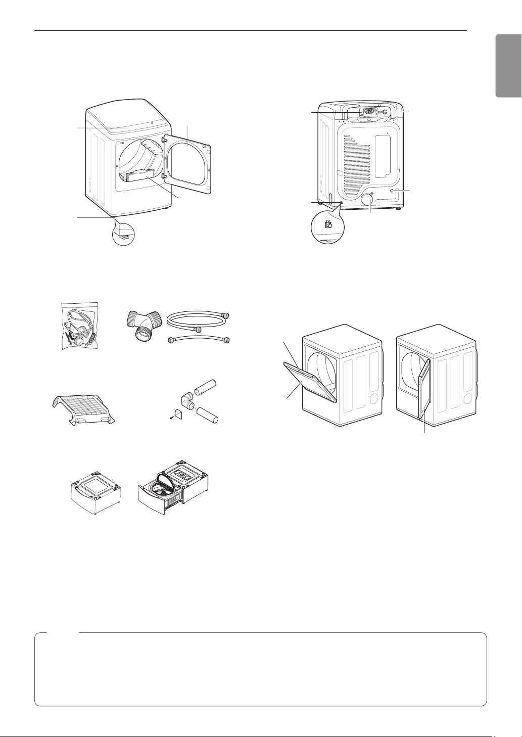
Parts
Reversible
Control
panel
Leveling
feet
Accessories
Included Accessories
door
Lintlter
Terminal block
access panel
(electric models)
Gas connection
location
(gas models)
Exhaust duct
outlet
Power cord
location
(gas models)
Water inlet valve
(on some models)
Two-Way Reversible Door
(on some models)
Release
ENGLISH
Safety Tether Kit
(on some models)
Optional Accessories
Drying rack
(sold separately)
No. 3750EL0001C
(steam models)
Pedestal or Pedestal Washer
(sold separately)
Y connector
(sold separately)
Kit No. 383EEL9001B
Hoses
(steam models)
Side vent kit
Hamper
door
Swing door
The LG EasyLoad™ feature allows you to open the
dryer door from the top, hamper-style, when loading the
dryer to help guide clothes into the drum and prevent
them from falling onto the floor. When unloading the
dryer or loading bulkier items, use the swing door for
easy access to the drum.
Safety Tether Kit
This optional kit helps prevent the dryer tipping if children climb on the door or if someone should fall onto the
door. It is recommended that you install this kit, depending on your situation, but it is not required. Follow the
customer installation instructions included with the kit to properly install the kit. If you do not install the kit, store it
out of reach of children.
NOTE
•For your safety and for extended product life, use only authorized components. The manufacturer is not
responsible for product malfunction or accidents caused by the use of separately purchased unauthorized
components or parts.
•The images in this guide may be different from the actual components and accessories, which are subject
to change by the manufacturer without prior notice for product improvement purposes.
10
INSTALLATION
INSTALLATION
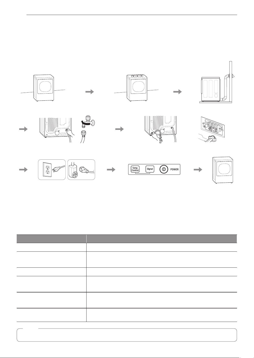
Installation Overview
Please read the following installation instructions first after purchasing this product or transporting it to another
location.
Check and choose
the proper location
Connect the inlet hose
(steam models)
Gas dryer Electric dryer
Plug in the power cord Installation test Test run
Level the dryer
Connect gas dryers
Vent the dryer
Connect electric dryers
Product Specifications
The appearance and specifications listed in this manual may vary due to constant product improvements.
Dryer Models DLEY1901*E, DLGY1902*E
Electrical requirements Please refer to the rating label regarding detailed information.
Gas requirements
Max. water pressure 20–120 psi (138–827 kPa)
Dimensions
Net weight
Drying capacity
- Normal cycle IEC 7.3 cu.ft. (22.5 lb/10.2 kg)
NOTE
Model numbers can be found on the cabinet inside the door.
NG: 4–10.5-inch WC
LP: 8–13-inch WC
27” (W) X 28 15/16” (D) X 40 3/16” (H), 50 1/4” (D with door open)
68.6 cm (W) X 73.4 cm (D) X 102 cm (H), 127.5 cm (D with door open)
Gas dryer : 136 lb (61.7 kg) –138 lb (62.6 kg)
Electric dryer : 133.5 lb (60.6 kg) –134.5 lb (61.0 kg)

INSTALLATION
11
Installation Location Requirements
WARNING
Read all installation instructions completely before installing and operating the dryer! It is important that you
review this entire manual before installing and using the dryer. Detailed instructions concerning electrical
connections, gas connections, and exhaust requirements are provided on the following pages.
The installation requires:
•A location that allows for proper exhaust installation. A gas dryer must be exhausted to the outdoors. See
Venting the Dryer.
•A grounded electrical outlet located within 2 ft. (61 cm) of either side of the dryer. See Connecting Electric
Dryers .
•A sturdy floor to support the total dryer weight of 200 lb (90.7 kg). The combined weight of a companion
appliance should also be considered.
•No other fuel-burning appliance can be installed in the same closet as a dryer.
Do not operate the dryer at temperatures below 45 °F (7 °C). At lower temperatures, the dryer might not shut off
at the end of an automatic cycle. This can result in longer drying times. The dryer must not be installed or stored
in an area where it will be exposed to water and/or weather. Check code requirements. Some codes limit, or do
not permit, installation of the dryer in garages, closets, mobile homes or sleeping quarters. Contact your local
building inspector.
NOTE
•The floor must be level, with a maximum slope of 1 inch (2.5 cm) under the entire dryer.
Clothes may not tumble properly, and automatic sensor cycles may not operate correctly if dryer is not
level.
•For a garage installation, you will need to place the dryer at least 18 inches (46 cm) above the floor. The
standard pedestal is 15 inches (38.1 cm). You will need 18 inches (46 cm) from the garage floor to the
bottom of the dryer.
ENGLISH
Clearances
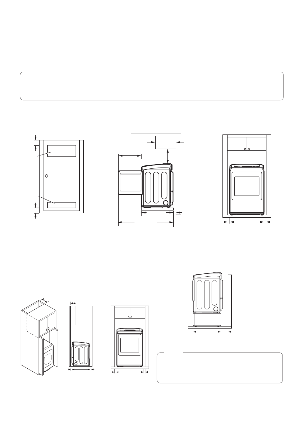
Installation Spacing for Recessed Area or Closet Installation
The following spacing dimensions are recommended for this dryer. This dryer has been tested for clearances of
1 inch (2.5 cm) on the sides and rear. Recommended clearances should be considered for the following reasons:
•Additional clearances should be considered for ease of installation and servicing.
•Additional clearances might be required for wall, door and floor moldings.
•Additional clearances should be considered on all sides of the dryer to reduce noise transfer.
For closet installation, with a door, minimum ventilation openings in the top and bottom of the door are
required. Louvered doors with equivalent ventilation openings are acceptable.
•Companion appliance spacing should also be considered.
12
INSTALLATION
Closet Ventilation Requirements
Closets with doors must have both an upper and lower vent to prevent heat and moisture buildup in the closet.
One upper vent opening with a minimum opening of 48 sq. in. (310 cm
2
) must be installed no lower than 6 feet
above the floor. One lower vent opening with a minimum opening of 24 sq. in. (155 cm2) must be installed no
more than one foot above the floor. Install vent grills in the door or cut down the door at the top and bottom to
form openings. Louvered doors with equivalent ventilation openings are also acceptable.
NOTE
There should be at least a little space around the dryer (or any other appliance) to eliminate the transfer of
vibration from one appliance to another. If there is enough vibration, it could cause appliances to make noise
or come into contact, causing paint damage and further increasing noise.
Installation Spacing for Recessed Area or Closet
3"
(7.6 cm)
14" max.*
(35.6 cm)
18" min.
(45.7 cm)
48 in.
(310 cm2)
1
21
/4"
2
(54 cm)
2
24 in.
(155 cm2)
15
/16"
28
(73.4 cm)
1
/4"
50
(127.5 cm)
1"
(2.5 cm)
3"
(7.6 cm)
Closet Door Vent
Requirements
* Required spacing
Installation Spacing for Cabinet Installing on a pedestal
For cabinet installation with a door, minimum ventilation
openings in the top of the cabinet are required.
* Required spacing
7"* (17.8 cm)
(12.7 cm)
7"* (17.8 cm)
5"
*
15
/16"
28
(73.4 cm)
1"
*
(2.5 cm)
1"
(2.5 cm)
27"
(68.6 cm)
1"
(2.5 cm)
2815/16"
(73.4 cm)
NOTE
Refer to the instructions packaged with the
optional pedestal kit before installing with a
pedestal kit.
27"
(68.6 cm)
5"
(12.7 cm)
1"
(2.5 cm)
INSTALLATION
13
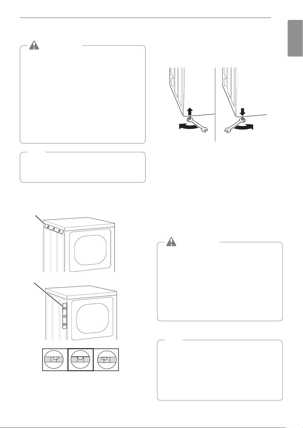
Leveling the Dryer
WARNING
To reduce the risk of injury to persons, adhere
to all industry recommended safety procedures
including the use of long-sleeved gloves and
safety glasses. Failure to follow this warning may
result in serious injury or death.
•The appliance is heavy. Two or more people
are required when installing the dryer. Failure to
follow this warning may result in serious injury
or death.
•To ensure that the dryer provides optimal drying
performance, it must be level. To minimize
vibration, noise, and unwanted movement, the
floor must be a perfectly level, solid surface.
NOTE
Adjust the leveling feet only as far as necessary
to level the dryer. Extending the leveling feet more
than necessary may cause the dryer to vibrate.
Position the dryer in the final location. Check
1
levelness of dryer from side to side. Repeat from
front to back.
Place level here
Use an adjustable wrench to turn the leveling
2
feet. Unscrew the legs to raise the dryer or
screw in the legs to lower it. Raise or lower with
the leveling feet until the dryer is level from side
to side and front to back. Make sure that all four
leveling feet are in firm contact with the floor.
If you are installing the dryer on the optional pedestal,
you must use the leveling feet on the pedestal to level the
dryer. The dryer leveling feet should be fully retracted.
Reversing the Door
Tools Required
Phillips or large flat-blade screwdriver (for hinge screws)
Small flat-blade screwdriver (for lifting out parts)
ENGLISH
Place level here
Not Level Not LevelLevel
WARNING
The dryer door is very large and heavy.
Failure to follow the instructions below can result
in damage to the dryer, property damage or
personal injury.
•To avoid damage to the dryer or the door,
support the door with a stool or box that fits
under the door, or have an assistant support
the weight of the door.
•Avoid dropping the door to prevent damage to
the door or the floor.
•Unplug the dryer or turn off power at the main
circuit breaker before beginning door reversal.
Door Reversal Instructions
NOTE
The instructions here are for changing the door
swing from a right to a left side hinge. If the
door has been reversed, and it is necessary to
change it back, use care when following these
instructions.
Some of the illustrations and the left/right
references will be reversed, and you will need to
read the instructions carefully.
14
INSTALLATION
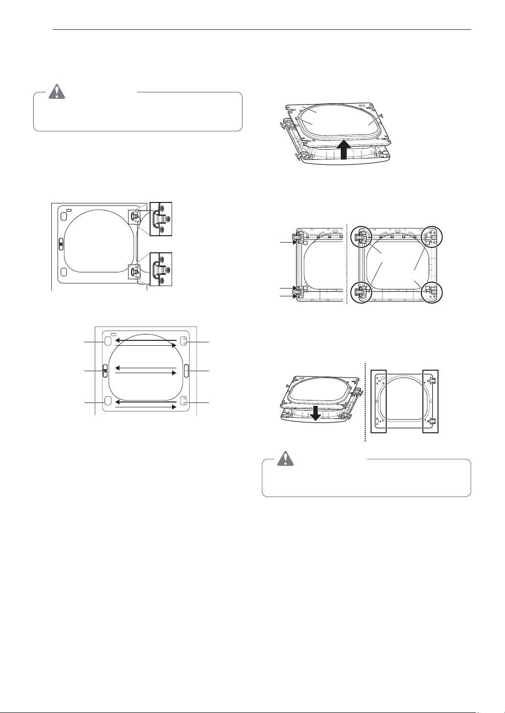
Swing door
Open the door from the side so that the hinge
1
screws are accessible.
WARNING
Be sure to support the weight of the door before
removing the hinge screws.
Remove the four hinge screws.
2
While supporting the door, remove the four hinge
screws, two from each hinge. Set the door aside
face down on a protected surface to prevent
damage to the door or the work surface.
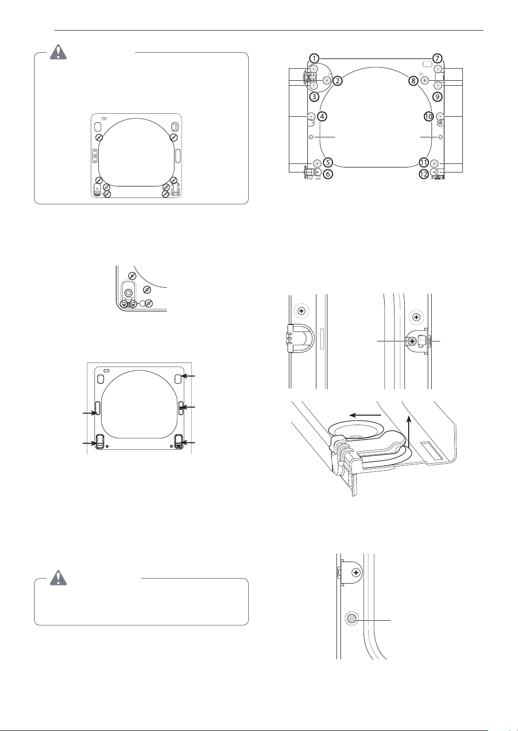
Reverse the components on the cabinet.
3
hinge
cover
latch
mechanism
hinge
latch
hole
cover
With the door on a protected surface, remove
4
the 16 screws on the sides of the door and
lift off the inner door frame using a flat blade
screwdriver. Remove the latch hook and blank
and install them on the opposite side.
Inner door
frame
Latch hookBlank
Remove the 4 screws securing the hinges to
5
the door frame. Remove the two plastic cover
caps. Reinstall the hinges and cover caps on the
opposite sides from which they were removed.
Hinge
assembly
Cover cap
With the hinges and cover caps in the new
6
locations, remount the inner door frame onto the
outer door frame with the screws removed in
step 4 above.
hinge
cover
a. Use a Phillips screwdriver to remove the two
screws and the latch mechanism on the front
panel of the cabinet.
b. Remove the latch hole cover by gently prying it
up with a flat blade screwdriver, being careful
not to scratch the paint. Install the latch hole
cover on the opposite side, where the latch
mechanism was removed. Install the latch
mechanism in the position from which you
removed the latch hole cover, using the two
screws removed in step a.
c. Remove the hinge cover by gently prying it up
with a flat blade screwdriver, being careful not
to scratch the paint. Rotate the hinge cover
180 degrees and install it on the opposite side,
where the hinge was attached.
hinge
WARNING
Be sure to support the weight of the door before
installing the hinge screws.
INSTALLATION
15
Reinstall the door.
7
While supporting the door, install the four hinge
screws removed in step 2. Test the swing of
the door to make sure the hinges and latch are
properly aligned and that the door opens, closes
and latches properly.
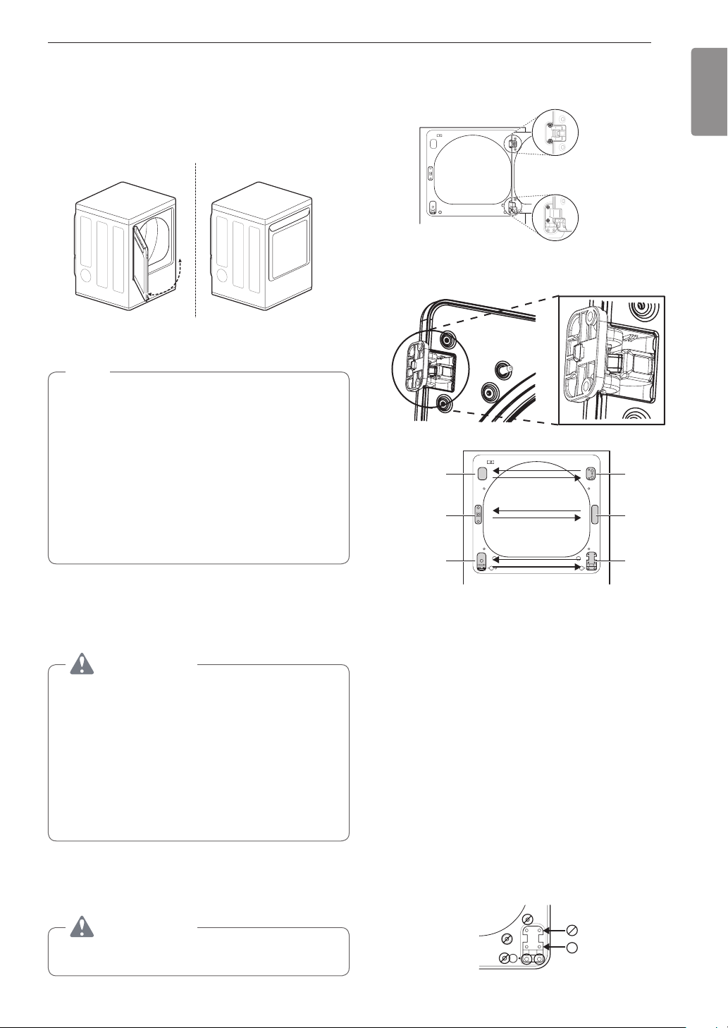
Swing
Door
LG EasyLoad™ Door (on some models)
NOTE
The door reversal procedure for the Easy Load
door is far more complex than for a conventional
swing door. Read through these instructions in
their entirety before beginning the process, to
judge whether you prefer to have the procedure
done by a professional installer or service person.
The instructions here are for changing the door
swing from a right to a left side hinge. If the door
has been reversed, and it is necessary to change
it back, use care when following these instructions.
Some of the illustrations and the left/right
references will be reversed, and you will need to
read the instructions carefully.
Remove the door from cabinet.
2
a. While supporting the door, remove the four
hinge screws.
Two large
screws
Two small
screws
b. Lift the door slightly to disengage the hinge
support and remove the door from the cabinet.
Set the door aside face down on a protected
work surface.
Reverse the components on the cabinet.
3
Hinge
cover
latch
mechanism
Hinge
Upper
hinge
Latch
hole
cover
Hinge
bracket
ENGLISH
Tools Required
Phillips or large flat-blade screwdriver (for hinge screws)
Small flat-blade screwdriver (for lifting out parts)
WARNING
The dryer door is very large and heavy.
Failure to follow the instructions below can result
in damage to the dryer, property damage or
personal injury.
•To avoid damage to the dryer or the door,
support the door with a stool or box that fits
under the door, or have an assistant support
the weight of the door.
•Avoid dropping the door to prevent damage to
the door or the floor.
•Unplug the dryer or turn off power at the main
circuit breaker before beginning door reversal.
ON THE CABINET :
Open the door from the side so that the hinge
1
screws are accessible.
WARNING
Be sure to support the weight of the door before
installing the hinge screws.
a. Use a Phillips screwdriver to remove the two
screws and the latch mechanism on the front
panel of the cabinet.
b. Remove the latch hole cover by gently prying it
up with a flat blade screwdriver, being careful
not to scratch the paint. Install the latch hole
cover on the opposite side, where the latch
mechanism was removed. Install the latch
mechanism in the position from which you
removed the latch hole cover, using the two
screws removed in step a.
c. Remove the hinge cover by gently prying it up
with a flat blade screwdriver, being careful not
to scratch the paint. Rotate the hinge cover
180 degrees and install it on the opposite side,
where the upper hinge was attached.
d. Reverse the hinge and the hinge bracket at
the bottom of the cabinet. Remove the two
screws from the hinge bracket at the bottom
right and remove the hinge bracket. Remove
the lower of the two screws behind the hinge
bracket. Do NOT remove the upper screw
behind the hinge bracket. Set the parts aside.
16
INSTALLATION
CAUTION
Do NOT remove any of the eight screws on the
face of the cabinet (marked below). Doing so
could result in damage to the dryer and the need
for a service call to repair the dryer.
e. Remove the three screws on the hinge at the
bottom left. Remove the hinge and reinstall it
on the right side. The top screw will occupy
the hole where you removed the screw behind
the hinge bracket in step d.
f. Install the hinge bracket removed in step d on
the bottom left side, first installing one screw
behind the hinge bracket.
Cabinet Reversal complete
Twelve screws
Hole
plug
Switch the door strike and the blank cover.
5
Remove the two screws on the door cover that
Side
Interlock
button
secure the door strike.
Switch the door strike and the blank cover,
installing them on the opposite sides from which
they were removed.
It may be difficult to insert the two screws in the
door strike on the opposite side. Use a cordless
screwdriver if necessary.
Short
screws
Long
screw
hinge
cover
latch hole
cover
hinge
bracket
latch
mechanism
hinge
ON THE DOOR:
Lift off the door cover.
4
With the door laid inside facing up on a
protected surface, remove the twelve screws on
the inside of the door. (The two bottom screws
will be different from the rest.) Carefully lift off
the door cover with the help of a small flat blade
screwdriver inserted in the upper left corner.
WARNING
The edges of the door cover may be sharp. Take
care when handling, or wear gloves to avoid
injury.
Blank cover Door strike
Pull
Raise
Remove blank cover
Gently pry out the hole plug on the side of
the door cover and install it in the hole on the
opposite side.
Hole
plug
Set the door cover aside.
INSTALLATION
17
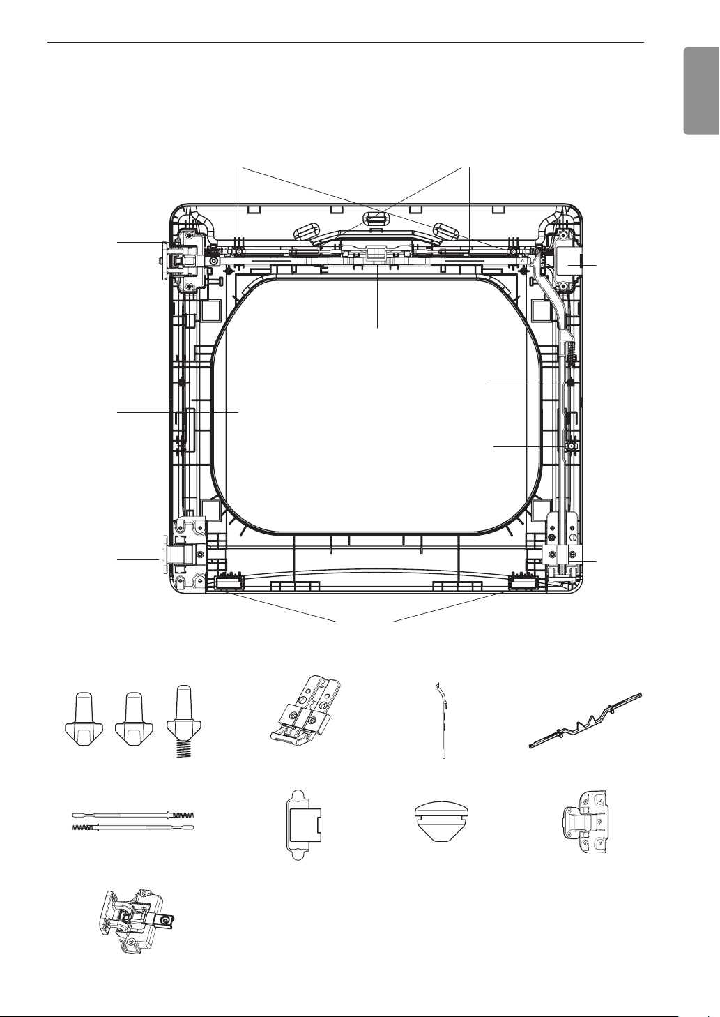
Reverse the components inside the door.
6
You will now be removing and reversing various components inside the door. See below for a detailed
diagram and identification of the inner structure and parts of the door. (The diagram shows the “before view”
of the door, with the default set-up for a right side hinge swing. After following these instructions, the door
should be a mirror image of the illustration.)
Inner lock rodsTop interlock buttons
Upper
hinge
assembly
Top lock rod
Side lock rod
Glass
Side Interlock button
Upper
hingeller
ENGLISH
Lower
hinge
assembly
Interlock buttons
Inner lock rods
Bumpers
Lower hinge bracket
Upperhingeller
Side lock rod
Hole plug
Lower
hinge
bracket
Top lock rod
Lower hinge assembly
Upper hinge assembly
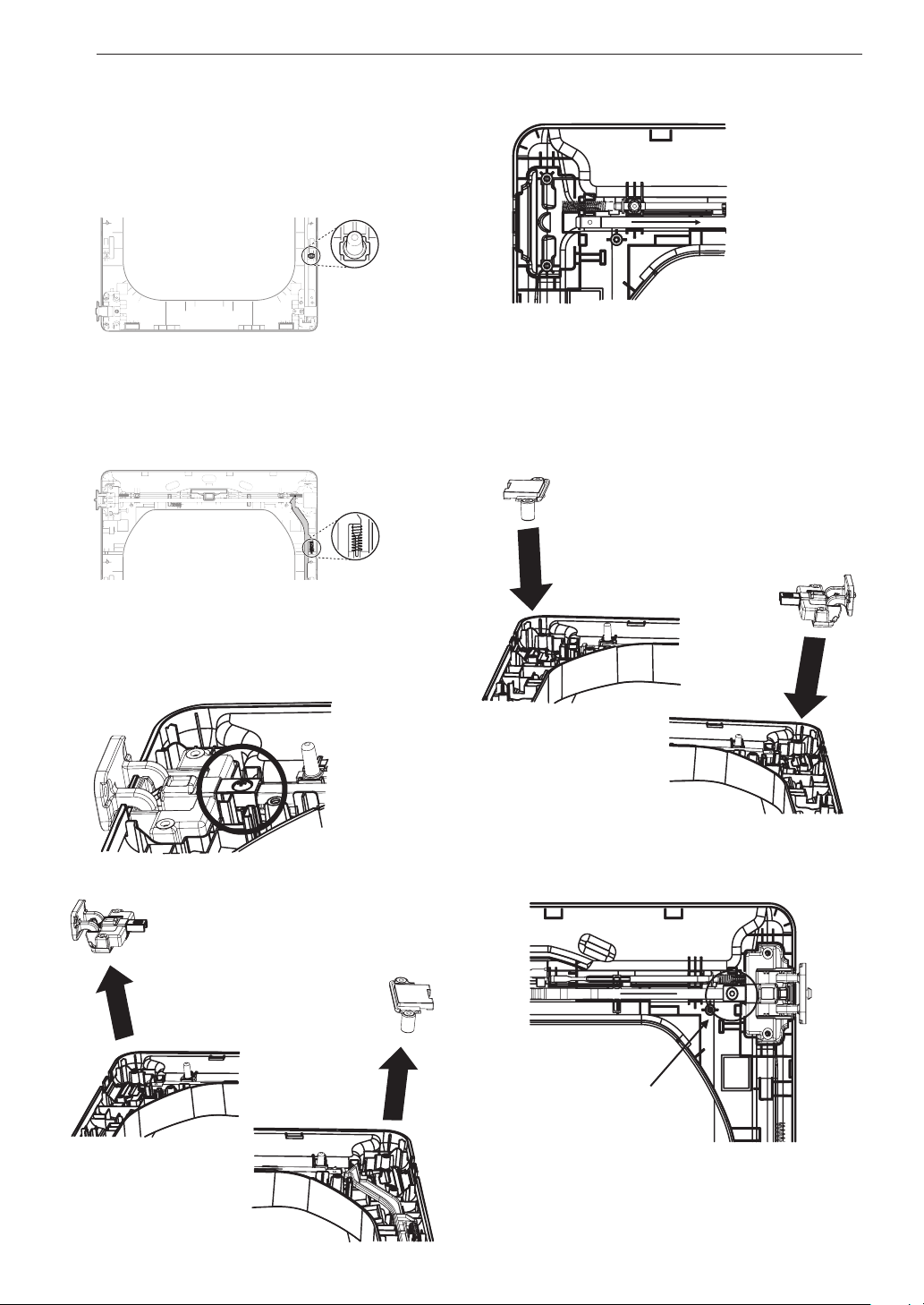
18
INSTALLATION
Lift out the gray interlock button in the side
7
of the door.
Make sure to remove the spring with the
interlock button and to keep the two together.
Set the interlock button aside. Do not confuse
this with the interlock buttons from the top of the
outer door.
Remove the side lock rod.
8
Remove the side lock rod from the lower hinge
bracket by lifting the top end of the rod and
sliding it toward the top of the door. The spring
should remain attached to the lock rod. Set the
lock rod aside.
Spring
c. Lift out the upper hinge assembly (on the left).
d. Slide the upper lock rod to the right. Rotate
the upper hinge assembly 180 degrees, and
install it over the lock rod on the right, where
youremovedtheupperhingeller.Press
rmlytofullyseatthehingeassembly.
e.Rotatethehingeller180degreesandinstall
it on the upper left side of the door.
Reverse the upper hinge assembly and hinge
9
filler.
a. Remove the screw connecting the upper
hinge assembly to the top lock rod and set it
aside.
b. Lift out the upper hinge filler (on the right) and
set it aside.
f. Insert and tighten the screw connecting the
upper hinge assembly to the top lock rod,
removed in step a.
Assemble screw
 Loading...