

LG DLEX5680VE/00 Owner’s Manual
ESPAÑOL ENGLISH
OWNER’S MANUAL
DRYER
Please read this owner’s manual thoroughly before operating and keep it handy for reference at all times.
DLEX5680*E DLGX5681*E
MFL67731020 |
www.lg.com |

2TABLE OF CONTENTS
TABLE OF CONTENTS
3 |
IMPORTANT SAFETY INSTRUCTIONS |
39 |
Custom Program |
|
39 |
Steam Functions |
|||
|
|
|||
|
|
3 WHAT TO DO IF YOU SMELL GAS
4BASIC SAFETY PRECAUTIONS
4CALIFORNIA SAFE DRINKING WATER AND
TOXIC ENFORCEMENT ACT
5GROUNDING INSTRUCTIONS
5SAFETY INSTRUCTIONS FOR INSTALLATION
7SAFETY INSTRUCTIONS FOR CONNECTING ELECTRICITY
8PRODUCT FEATURES
9INTRODUCING YOUR DRYER
9Parts and Accessories
92-Way Reversible Door
10Control Panel Features
11Display
41Steam Cycle Guide
42MAINTENANCE
42Regular Cleaning
43TROUBLESHOOTING
43 Before Calling for Service
46SPECIFICATIONS
47USING SMART DIAGNOSIS™
48WARRANTY
12 INSTALLATION INSTRUCTIONS
12Preview Installation Order
13Installation Location Requirements
13Clearances
14Leveling the Dryer
15Reversing the Door
21Installing the Side Vent Kit
22Venting the Dryer
24 Connecting Gas Dryers
26 Connecting Electric Dryers
31 Special Requirements for Manufactured or Mobile Homes
31Final Installation Check
32Installation Test (Duct Check)
34 HOW TO USE
34Operating the Dryer
35Sorting Loads
35Check the Lint Filter Before Every Load
35Loading the Dryer
36Using the LG EasyLoad™
37Cycle Guide
38Cycle Settings and Options
38 Special Functions

IMPORTANT SAFETY INSTRUCTIONS |
3 |
IMPORTANT SAFETY INSTRUCTIONS
READ ALL INSTRUCTIONS BEFORE USE
WWARNING
For your safety, the information in this manual must be followed to minimize the risk of fire or explosion, electric shock, or to prevent property damage, injury to persons, or death.
Your safety and the safety of others is very important.
We have provided many important safety messages in this manual and on your appliance. Always read and obey all safety messages.
W |
This is the safety alert symbol. |
This symbol alerts you to potential hazards that can kill or hurt you and others. |
All safety messages will follow the safety alert symbol and either the word DANGER, WARNING, or CAUTION.
These words mean:
WDANGER
You will be killed or seriously injured if you don’t immediately follow instructions.
WWARNING
You can be killed or seriously injured if you don’t follow instructions.
WCAUTION
You may be slightly injured or cause damage to the product if you do not follow instructions.
All safety messages will tell you what the potential hazard is, tell you how to reduce the chance of injury, and tell you what can happen if the instructions are not followed.
t %P OPU JOTUBMM B DMPUIFT ESZFS XJUI GMFYJCMF QMBTUJD WFOUJOH NBUFSJBMT *G GMFYJCMF NFUBM GPJM UZQF EVDU JT JOTUBMMFE JU NVTU CF PG B TQFDJGJD UZQF JEFOUJGJFE CZ UIF BQQMJBODF NBOVGBDUVSFS BT TVJUBCMF GPS VTF XJUI DMPUIFT ESZFST 'MFYJCMF WFOUJOH NBUFSJBMT BSF LOPXO UP DPMMBQTF CF FBTJMZ DSVTIFE BOE USBQ MJOU 5IFTF DPOEJUJPOT XJMM PCTUSVDU DMPUIFT ESZFS BJSGMPX BOE JODSFBTF UIF SJTL PG GJSF
t %P OPU TUPSF PS VTF HBTPMJOF PS PUIFS GMBNNBCMF WBQPST BOE MJRVJET JO UIF WJDJOJUZ PG UIJT BQQMJBODF PS BOZ PUIFS BQQMJBODFT
t *OTUBMMBUJPO BOE TFSWJDF NVTU CF QFSGPSNFE CZ B RVBMJGJFE JOTUBMMFS TFSWJDF BHFODZ PS UIF HBT TVQQMJFS t *OTUBMM UIF DMPUIFT ESZFS BDDPSEJOH UP UIF NBOVGBDUVSFST JOTUSVDUJPOT BOE MPDBM DPEFT t 4BWF UIFTF JOTUSVDUJPOT
8)"550 %0 *':06 4.&-- ("4
%P OPU USZ UP MJHIU B NBUDI PS DJHBSFUUF PS UVSO PO BOZ HBT PS FMFDUSJDBM BQQMJBODF%P OPU UPVDI BOZ FMFDUSJDBM TXJUDIFT %P OPU VTF BOZ QIPOF JO ZPVS CVJMEJOH$MFBS UIF SPPN CVJMEJOH PS BSFB PG BMM PDDVQBOUT*NNFEJBUFMZ DBMM ZPVS HBT TVQQMJFS GSPN B OFJHICPST QIPOF 'PMMPX UIF HBT TVQQMJFST JOTUSVDUJPOT DBSFGVMMZ*G ZPV DBOOPU SFBDI ZPVS HBT TVQQMJFS DBMM UIF GJSF EFQBSUNFOU
WWARNING:This product contains chemicals known to the State of California to cause cancer and birth defects or other reproductive harm. Wash hands after handling.
ENGLISH

4IMPORTANT SAFETY INSTRUCTIONS
IMPORTANT SAFETY INSTRUCTIONS
READ ALL INSTRUCTIONS BEFORE USE
WWARNING
For your safety, the information in this manual must be followed to minimize the risk of fire or explosion, electric shock, or to prevent property damage, injury to persons, or death.
#"4*$ 4"'&5: 13&$"65*0/4
WWARNING
To reduce the risk of fire, electric shock, or injury to persons when using this appliance, follow basic precautions, including the following:
t 3FBE BMM JOTUSVDUJPOT CFGPSF VTJOH UIF ESZFS
t #FGPSF VTF UIF ESZFS NVTU CF QSPQFSMZ JOTUBMMFE BT described in this manual.
t %P OPU QMBDF JUFNT FYQPTFE UP DPPLJOH PJMT JO ZPVS dryer. Items contaminated with cooking oils may contribute to a chemical reaction that could cause a load to catch fire.
t %P OPU ESZ BSUJDMFT UIBU IBWF CFFO QSFWJPVTMZ DMFBOFE in, washed in, soaked in, or spotted with gasoline, drycleaning solvents, or other flammable or explosive substances as they give off vapors that could ignite or explode.
t %P OPU SFBDI JOUP UIF ESZFS JG UIF ESVN PS BOZ PUIFS part is moving.
t %P OPU SFQBJS PS SFQMBDF BOZ QBSU PG UIF ESZFS or attempt any servicing unless specifically
recommended in this owner’s manual or in published user-repair instructions that you understand and have the skills to carry out.
t %P OPU UBNQFS XJUI DPOUSPMT
t #FGPSF UIF ESZFS JT SFNPWFE GSPN TFSWJDF PS EJTDBSEFE remove the door to the drying compartment.
t %P OPU BMMPX DIJMESFO UP QMBZ PO PS JO UIF ESZFS $MPTF supervision of children is necessary when the dryer is used near children.
t %P OPU VTF GBCSJD TPGUFOFST PS QSPEVDUT UP FMJNJOBUF static unless recommended by the manufacturer of the fabric softener or product.
t %P OPU VTF IFBU UP ESZ BSUJDMFT DPOUBJOJOH GPBN SVCCFS or similarly textured rubber-like materials.
t ,FFQ BSFB BSPVOE UIF FYIBVTU PQFOJOH BOE BEKBDFOU surrounding areas free from the accumulation of lint, dust, and dirt.
t5IF JOUFSJPS PG UIF ESZFS BOE FYIBVTU WFOU TIPVME CF cleaned periodically by qualified service personnel.
t %P OPU JOTUBMM PS TUPSF UIF ESZFS XIFSF JU XJMM CF exposed to the weather.
t "MXBZT DIFDL UIF JOTJEF PG UIF ESZFS GPS GPSFJHO objects.
t $MFBO MJOU TDSFFO CFGPSF PS BGUFS FBDI MPBE
t %P OPU TUPSF QMBTUJD QBQFS PS DMPUIJOH UIBU NBZ
CVSO PS NFMU PO UPQ PG UIF ESZFS EVSJOH PQFSBUJPO
t #F DBSFGVM XIFO PQFOJOH BOE DMPTJOH UIF EPPS'JOHFST and hands can get caught in the door and cause injury if the door drops forward unexpectedly.
t %P OPU QMBDF IFBWZ JUFNT PO PS MFBO BHBJOTU UIF UPQ
PG UIF EPPS XIFO JU JT PQFO
t %P OPU BUUFNQU UP QVMM UIF IBNQFS EPPS PQFO NPSF
UIBO EFHSFFT
t5IF ESZFS DPVME UJQ GPSXBSE DBVTJOH JOKVSZ PS EBNBHF
$"-*'03/*" 4"'& %3*/,*/( 8"5&3 "/% 509*$ &/'03$&.&/5 "$5
This act requires the governor of California to publish a list of substances known to the state to cause cancer, birth defects, or other reproductive harm and requires businesses to warn customers of potential exposure to such substances.
Gas appliances can cause minor exposure to four of these substances, namely benzene, carbon monoxide, formaldehyde, and soot, caused primarily by the incomplete combustion of natural gas or LP fuels.
Properly adjusted dryers will minimize incomplete combustion. Exposure to these substances can be minimized further by properly venting the dryer to the outdoors.

IMPORTANT SAFETY INSTRUCTIONS |
5 |
IMPORTANT SAFETY INSTRUCTIONS
READ ALL INSTRUCTIONS BEFORE USE
WWARNING
For your safety, the information in this manual must be followed to minimize the risk of fire or explosion, electric shock, or to prevent property damage, injury to persons, or death.
(306/%*/( */4536$5*0/4
This appliance must be grounded. In the event of malfunction or breakdown, grounding will reduce the risk of electric shock by providing a path of least resistance for electric current. This appliance must be
equipped with a cord having an equipment-grounding conductor and a grounding plug. The plug must be plugged into an appropriate outlet that is properly installed and grounded in accordance with all local codes and ordinances.
Do not modify the plug provided with the appliance. If it will not fit the outlet, have a proper outlet installed by a qualified electrician.
This appliance must be connected to a grounded metal, permanent wiring system or an equipment-grounding conductor must be run with the circuit conductors and connected to the equipment-grounding terminal or lead on the appliance.
Electric shock can result if the dryer is not properly grounded.
WWARNING
Improper connection of the equipment-grounding conductor can result in a risk of electric shock. Check with a qualified electrician or service person if you are in doubt that the appliance is properly grounded.
4"'&5: */4536$5*0/4 '03 */45"--"5*0/
WWARNING
To reduce the risk of fire, electric shock, or injury to persons when using this appliance, follow basic precautions, including the following:
t1SPQFSMZ HSPVOE ESZFS UP DPOGPSN XJUI BMM HPWFSOJOH DPEFT BOE PSEJOBODFT Follow details in the installation instructions. Electric shock can result if the dryer is not properly grounded.
t#FGPSF VTF UIF ESZFS NVTU CF QSPQFSMZ JOTUBMMFE as described in this manual. Electric shock can result if the dryer is not properly grounded.
t*OTUBMM BOE TUPSF UIF ESZFS XIFSF JU XJMM OPU CF
FYQPTFE UP UFNQFSBUVSFT CFMPX GSFF[JOH PS FYQPTFE UP UIF XFBUIFS
t"MM SFQBJST BOE TFSWJDJOH NVTU CF QFSGPSNFE
CZ BO BVUIPSJ[FE TFSWJDFS VOMFTT TQFDJGJDBMMZ SFDPNNFOEFE JO UIJT PXOFST NBOVBM 6TF POMZ BVUIPSJ[FE GBDUPSZ QBSUT Failure to follow this warning can cause serious injury, fire, electric shock, or death.
t5P SFEVDF UIF SJTL PG FMFDUSJD TIPDL EP OPU JOTUBMM UIF ESZFS JO IVNJE TQBDFT Failure to follow this warning can cause serious injury, fire, electric shock, or death.
t$POOFDU UP B QSPQFSMZ SBUFE QSPUFDUFE BOE TJ[FE QPXFS DJSDVJU UP BWPJE FMFDUSJDBM PWFSMPBE Improper power circuit can melt, creating electric shock and/or fire hazard.
t3FNPWF BMM QBDLJOH JUFNT BOE EJTQPTF PG BMM TIJQQJOH NBUFSJBMT QSPQFSMZ Failure to do so can result in death, explosion, fire, or burns.
t1MBDF ESZFS BU MFBTU JODIFT BCPWF UIF GMPPS GPS B HBSBHF JOTUBMMBUJPO Failure to do so can result in death, explosion, fire, or burns.
t,FFQ BMM QBDLBHJOH GSPN DIJMESFO Packaging material can be dangerous for children. There is a risk of suffocation.
t%P OPU JOTUBMM OFBS BOPUIFS TPVSDF PG IFBU TVDI BT B TUPWF DPPLJOH PWFO Failure to do so can cause deform, smoke and fire.
t%P OPU QMBDF DBOEMFT TNPLJOH NBUFSJBMT PS PUIFS GMBNNBCMFT PO UPQ PG UIF QSPEVDU Dripping wax, smoke, or fire can result.
t3FNPWF BMM QSPUFDUJWF WJOZM GJMN GSPN UIF QSPEVDU
Failure to do so can cause product damage, smoke or fire.
ENGLISH

6IMPORTANT SAFETY INSTRUCTIONS
IMPORTANT SAFETY INSTRUCTIONS
READ ALL INSTRUCTIONS BEFORE USE
WWARNING
For your safety, the information in this manual must be followed to minimize the risk of fire or explosion, electric shock, or to prevent property damage, injury to persons, or death.
4"'&5: */4536$5*0/4 '03 */45"--"5*0/
WWARNING
To reduce the risk of injury to persons, follow all industry recommended safety procedures including the use of long sleeved gloves and safety glasses. Failure to follow all of the safety warnings in this manual could result in property damage, injury to persons, or death.
Exhaust/Ducting:
t(BT ESZFST .645 CF FYIBVTUFE UP UIF PVUTJEF
Failure to follow these instructions can result in fire or death.
t5IF ESZFS FYIBVTU TZTUFN NVTU CF FYIBVTUFE
UP UIF PVUTJEF PG UIF EXFMMJOH *G UIF ESZFS JT OPU FYIBVTUFE PVUEPPST TPNF GJOF MJOU BOE MBSHF BNPVOUT PG NPJTUVSF XJMM CF FYQFMMFE JOUP UIF MBVOESZ BSFB. An accumulation of lint in any area of the home can create a health and fire hazard.
t6TF POMZ SJHJE NFUBM PS GMFYJCMF NFUBM JODI
EJBNFUFS EVDUXPSL JOTJEF UIF ESZFS DBCJOFU PS GPS FYIBVTUJOH UP UIF PVUTJEF 6TF PG QMBTUJD PS PUIFS DPNCVTUJCMF EVDUXPSL DBO DBVTF B GJSF Punctured ductwork can cause a fire if it collapses or becomes otherwise restricted in use or during installation.
t%VDUXPSL JT OPU QSPWJEFE XJUI UIF ESZFS BOE ZPV
TIPVME PCUBJO UIF OFDFTTBSZ EVDUXPSL MPDBMMZ 5IF FOE DBQ TIPVME IBWF IJOHFE EBNQFST UP QSFWFOU CBDLESBGU XIFO UIF ESZFS JT OPU JO VTF Failure to follow these instructions can result in fire or death.
t5IF FYIBVTU EVDU NVTU CF JODIFT DN JO
EJBNFUFS XJUI OP PCTUSVDUJPOT 5IF FYIBVTU EVDU TIPVME CF LFQU BT TIPSU BT QPTTJCMF .BLF TVSF UP DMFBO BOZ PME EVDUT CFGPSF JOTUBMMJOH ZPVS OFX dryer. Failure to follow these instructions can result in fire or death.
t3JHJE PS TFNJ SJHJE NFUBM EVDUJOH JT SFDPNNFOEFE
GPS VTF CFUXFFO UIF ESZFS BOE UIF XBMM *O TQFDJBM JOTUBMMBUJPOT XIFO JU JT JNQPTTJCMF UP NBLF B DPOOFDUJPO XJUI UIF BCPWF SFDPNNFOEBUJPOT B 6- MJTUFE GMFYJCMF NFUBM USBOTJUJPO EVDU NBZ CF VTFE CFUXFFO UIF ESZFS BOE XBMM DPOOFDUJPO POMZ 5IF VTF PG UIJT EVDUJOH XJMM BGGFDU ESZJOH UJNF Failure to follow these instructions can result in fire or death.
t%0 /05 VTF TIFFU NFUBM TDSFXT PS PUIFS GBTUFOFST
XIJDI FYUFOE JOUP UIF EVDU UIBU DPVME DBUDI MJOU BOE SFEVDF UIF FGGJDJFODZ PG UIF FYIBVTU TZTUFN Secure all joints with duct tape. For complete details, follow the Installation Instructions. Failure to follow these instructions can result in fire or death.

IMPORTANT SAFETY INSTRUCTIONS |
7 |
IMPORTANT SAFETY INSTRUCTIONS
READ ALL INSTRUCTIONS BEFORE USE
WWARNING
For your safety, the information in this manual must be followed to minimize the risk of fire or explosion, electric shock, or to prevent property damage, injury to persons, or death.
4"'&5: */4536$5*0/4 '03 $0//&$5*/( &-&$53*$*5:
WWARNING
To reduce the risk of fire, electric shock, or injury to persons when using this appliance, follow basic precautions, including the following:
t%P OPU VOEFS BOZ DJSDVNTUBODFT DVU PS SFNPWF UIF HSPVOE QSPOH GSPN UIF QPXFS DPSE To prevent injury to persons or damage to the dryer, the electrical power cord must be plugged into a properly grounded outlet.
t'PS QFSTPOBM TBGFUZ UIJT ESZFS NVTU CF QSPQFSMZ HSPVOEFE Failure to do so can result in electric shock or injury.
t3FGFS UP UIF JOTUBMMBUJPO JOTUSVDUJPOT JO UIJT NBOVBM
GPS TQFDJGJD FMFDUSJDBM SFRVJSFNFOUT GPS ZPVS NPEFM
Failure to follow these instructions can create an electric shock hazard and/or a fire hazard.
t5IJT ESZFS NVTU CF QMVHHFE JOUP B QSPQFSMZ
HSPVOEFE PVUMFU &MFDUSJD TIPDL DBO SFTVMU JG UIF ESZFS JT OPU QSPQFSMZ HSPVOEFE )BWF UIF XBMM PVUMFU BOE DJSDVJU DIFDLFE CZ B RVBMJGJFE FMFDUSJDJBO UP NBLF TVSF UIF PVUMFU JT QSPQFSMZ HSPVOEFE
Failure to follow these instructions can create an electric shock hazard and/or a fire hazard.
t5IF ESZFS TIPVME BMXBZT CF QMVHHFE JOUP JUT PXO
JOEJWJEVBM FMFDUSJDBM PVUMFU XIJDI IBT B WPMUBHF SBUJOH UIBU NBUDIFT UIF SBUJOH QMBUF This provides sparkling performance and also prevents overloading house wiring circuits which could cause a fire hazard from overheated wires.
t/FWFS VOQMVH ZPVS ESZFS CZ QVMMJOH PO UIF QPXFS
DPSE "MXBZT HSJQ QMVH GJSNMZ BOE QVMM TUSBJHIU PVU GSPN UIF PVUMFU The power cord can be damaged, resulting in a risk of fire and electric shock.
t3FQBJS PS SFQMBDF JNNFEJBUFMZ BMM QPXFS DPSET UIBU
IBWF CFDPNF GSBZFE PS PUIFSXJTF EBNBHFE %P OPU VTF B DPSE UIBU TIPXT DSBDLT PS BCSBTJPO EBNBHF BMPOH JUT MFOHUI PS BU FJUIFS FOE The power cord can melt, creating an electric shock and/or fire hazard.
t8IFO JOTUBMMJOH PS NPWJOH UIF ESZFS CF DBSFGVM OPU UP QJODI DSVTI PS EBNBHF UIF QPXFS DPSE This will prevent injury and prevent damage to the dryer from fire and electric shock.
ENGLISH
4"7&5)&4& */4536$5*0/4

8PRODUCT FEATURES
PRODUCT FEATURES
EASY-TO-USE CONTROL PANEL
Rotate the cycle selector knob to select the desired dry cycle. Add cycle options or adjust settings with the touch of a button.
2-WAY EASY-ACCESS REVERSIBLE DOOR
The LG EasyLoad™ can be tilted open from the top, hamper-style, allowing you to easily load the dryer without items falling on the floor. The door still swings open to provide easy access for unloading or loading of bulkier items. The door hinge can be reversed to adjust for installation location.
STEAM FUNCTIONS
LG’s steam technology allows you to inject fabrics with a swirling jet of hot steam to refresh clothes, reduce static, and make ironing easier. Simply select the Steam Fresh™ cycle, or you can add a Steam option to selected cycles.
Flow Sense™ DUCT BLOCKAGE SENSING SYSTEM INDICATOR
The Flow Sense™ duct blockage sensing system detects and alerts you to restrictions in the installed household ductwork that reduce exhaust airflow through the dryer. If you see the alert: Clean or repair the ducts to remove
UIF SFTUSJDUJPOT ,FFQ ZPVS EVDUT DMFBO UP IFMQ JODSFBTF FGGJDJFODZ BOE SFEVDF MPOH ESZJOH UJNFT DBVTFE CZ CMPDLFE ducts.
Smart Diagnosis™
Should you experience any technical difficulty with your washing machine, it has the capability of transmitting data by phone to the Customer Information Center. The call center agent records the data transmitted from your machine and uses it to analyze the issue, providing a fast and effective diagnosis.
D
E
S
I
G
N
C E
R
T
I
|
D |
E |
|
FI |
|
Protocol P154
Sanitization Performance of Residential Clothes dryer
INTRODUCING YOUR DRYER |
9 |
INTRODUCING YOUR DRYER
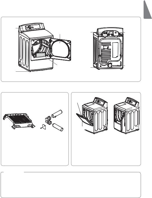
Parts and Accessories
Parts
Control |
Reversible |
|
panel |
||
door |
||
|
Lint filter
Leveling feet
Terminal |
Power cord |
block |
location |
access panel |
(Gas |
(Electric |
models) |
models) |
|
Gas |
Exhaust |
|
duct |
||
connection |
||
outlet |
||
location |
||
|
||
(Gas models) |
|
Accessories |
2-Way Reversible Door |
*ODMVEFE "DDFTTPSJFT 0QUJPOBM "DDFTTPSJFT
Release
ENGLISH
Drying rack |
Side vent kit |
Part No. |
(sold separately) |
3750EL0001C |
Kit No. |
|
383EEL9001B |
Hamper door 


 Swing door


The LG EasyLoad™ feature allows you to open the dryer door from the top, hamper-style, when loading the dryer to help guide clothes into the drum and prevent them from falling onto the floor. When unloading the dryer or loading bulkier items, use the swing door for easy access to the drum. For more details on using the
EPPS TFF QBHF 'PS JOGPSNBUJPO PO SFWFSTJOH UIF EPPS TXJOH TFF QBHF
 NOTE
NOTE
t $POUBDU -( $VTUPNFS 4FSWJDF BU JO $BOBEB JG BOZ BDDFTTPSJFT BSF NJTTJOH
t 'PS ZPVS TBGFUZ BOE GPS FYUFOEFE QSPEVDU MJGF VTF POMZ BVUIPSJ[FE DPNQPOFOUT 5IF NBOVGBDUVSFS JT OPU responsible for product malfunction or accidents caused by the use of separately purchased unauthorized components or parts.
t5IF JNBHFT JO UIJT PXOFST NBOVBM NBZ CF EJGGFSFOU GSPN UIF BDUVBM DPNQPOFOUT BOE BDDFTTPSJFT BOE BSF subject to change by the manufacturer without prior notice for product improvement purposes.

10 INTRODUCING YOUR DRYER
Control Panel Features
Following are instructions for starting and using your new dryer. Please refer to specific sections of this manual for more detailed information.
WWARNING
To reduce the risk of fire, electric shock, or injury to persons, read this entire manual, including the Important Safety Instructions, before operating this dryer.
Operation
|
|
Button |
%FTDSJQUJPO |
|
|
|
|
|
ü 1PXFS 0O 0GG #VUUPO |
|
|
|
|
- Press to turn the dryer On. Press again to turn the dryer Off. |
|
|
|
|
/05& Pressing the On/Off button during a cycle will cancel that cycle and any |
|
|
|
|
|
|
|
|
|
load settings will be lost. |
|
|
|
|
|
|
|
|
|
ü $ZDMF 4FMFDUPS ,OPC |
|
|
|
|
- Turn this knob to select the desired cycle. Once the desired cycle has been |
|
|
|
|
selected, the standard presets will be shown in the display. On Manual Dry |
|
|
|
|
cycles, these settings can be adjusted using the cycle setting buttons anytime |
|
|
|
|
before starting the cycle. |
ü4UBSU 1BVTF #VUUPO
- Press this button to Start the selected cycle. If the dryer is running, use this
button to Pause the cycle without losing the current settings.
/05& *G ZPV EP OPU QSFTT UIF 4UBSU 1BVTF CVUUPO UP SFTVNF B DZDMF XJUIJO minutes, the dryer turns off automatically.
ü .PSF5JNF -FTT5JNF #VUUPOT
- To adjust the drying time, use these buttons with Manual Dry, Time Dry, and Steam Fresh™ cycles, as well as the Reduce Static and Easy Iron options. Press the More Time button to increase the selected manual cycle time by a minute; press Less Time to decrease the cycle time by a minute.
ü $ZDMF 4FUUJOH #VUUPOT
- Use these buttons to select the desired cycle settings for the selected cycle. The current settings are shown in the display. Press the button for that option to view and select other settings.
ü 0QUJPO #VUUPOT
- The Option buttons allow you to select additional cycle options. Certain buttons also allow you to activate special functions by pressing and holding
UIF CVUUPO GPS TFDPOET
ü 4UFBN 'VODUJPOT
- LG’s steam technology allows you to inject fabrics with a swirling jet of hot steam to refresh clothes, reduce static, and make ironing easier. Simply select the Steam Fresh™ cycle, or you can add a Steam option to selected cycles.
INTRODUCING YOUR DRYER 11
Display
The display shows the settings, estimated time remaining, options, and status messages for your dryer. When the dryer is turned on, the light in the display will illuminate.
WWARNING
To reduce the risk of fire, electric shock, or injury to persons, read this entire manual, including the Important Safety Instructions, before operating this dryer.
ENGLISH
|
Button |
%FTDSJQUJPO |
|
|
ü &TUJNBUFE5JNF 3FNBJOJOH |
|
|
- When the Start/Pause button is pressed, the dryer will display the estimated |
|
|
4FOTPS %SZ PS TFU UJNF 5JNF %SZ SFNBJOJOH BOE CFHJO UVNCMJOH |
|
|
/05& The cycle time on Sensor Dry cycles may fluctuate as the dryer |
|
|
recalculates drying time for optimal results |
|
|
|
|
|
ü $ZDMF $PNQMFUJPO *OEJDBUPS8JUI $IFDL 'JMUFS 3FNJOEFS |
|
|
- This portion of the display shows which stage of the drying cycle is currently |
|
|
VOEFSXBZ $MFBO 'JMUFS %SZJOH PS $PPMJOH |
|
|
|
|
|
|
|
|
|
ü $IJME -PDL *OEJDBUPS
-When Child Lock is set, the Child Lock indicator will appear and all buttons are disabled except the Power button. This prevents children from changing settings while the dryer is operating
ü $MFBO 'JMUFS 3FNJOEFS
- The display will show Clean Filter when the dryer is turned on as a reminder to check the filter. It turns off when the Start/Pause button is pressed.
ü$VTUPN 1SPHSBN
-If you have a special combination of settings that you use frequently, you can save these settings as a Custom Program.
ü'MPX 4FOTF %VDU #MPDLBHF 4FOTJOH 4ZTUFN *OEJDBUPS
- The Flow Sense™ duct blockage sensing system detects and alerts you to blockages in the ductwork that reduce exhaust flow from the dryer. This improves operating efficiency and helps minimize service calls, saving your money.
12 INSTALLATION INSTRUCTIONS
INSTALLATION INSTRUCTIONS
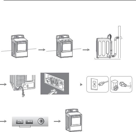
Preview Installation Order
Checking and choosing the |
Leveling the dryer |
Venting the dryer |
proper location |
|
|

 120V
120V  240V
240V
Connecting gas dryers |
Connecting electric dryers |
Plugging in the power cord |
|
|
and grounding |
Press and hold |
|
Installation test |
Test run |
(Refer to page 32.) |
|
INSTALLATION INSTRUCTIONS 13
Installation Location Requirements
WWARNING
3FBE BMM JOTUBMMBUJPO JOTUSVDUJPOT DPNQMFUFMZ CFGPSF JOTUBMMJOH BOE PQFSBUJOH ZPVS ESZFS It is important that you review this entire manual before installing and using your dryer. Detailed instructions concerning electrical connections, gas connections, and exhaust requirements are provided on the following pages.
t " MPDBUJPO UIBU BMMPXT GPS QSPQFS FYIBVTU JOTUBMMBUJPO " |
t " TUVSEZ GMPPS UP TVQQPSU UIF UPUBM ESZFS XFJHIU PG |
gas dryer must be exhausted to the outdoors. |
MCT LH 5IF DPNCJOFE XFJHIU PG B DPNQBOJPO |
See 7FOUJOH UIF ESZFS |
appliance should also be considered. |
t " HSPVOEFE FMFDUSJDBM PVUMFU MPDBUFE XJUIJO GU |
t No other fuel-burning appliance can be installed in the |
DN PG FJUIFS TJEF PG UIF ESZFS 4FF $POOFDUJOH |
same closet as a dryer. |
FMFDUSJD ESZFST |
|
%P OPU PQFSBUF ZPVS ESZFS BU UFNQFSBUVSFT CFMPX ¡' ¡$ "U MPXFS UFNQFSBUVSFT UIF ESZFS NJHIU OPU TIVU PGG at the end of an automatic cycle. This can result in longer drying times. The dryer must not be installed or stored in an area where it will be exposed to water and/or weather. Check code requirements. Some codes limit, or do not permit, installation of the dryer in garages, closets, mobile homes or sleeping quarters. Contact your local building inspector.
 NOTE
NOTE
t " MFWFM GMPPS XJUI B NBYJNVN TMPQF PG JODI DN VOEFS FOUJSF ESZFS *G TMPQF JT HSFBUFS UIBO JODI DN JOTUBMM UIF &YUFOEFE %SZFS 'FFU ,JU $MPUIFT NBZ OPU UVNCMF QSPQFSMZ BOE BVUPNBUJD TFOTPS DZDMFT NBZ OPU operate correctly if dryer is not level.
t 'PS B HBSBHF JOTUBMMBUJPO ZPV XJMM OFFE UP QMBDF UIF ESZFS BU MFBTU JODIFT DN BCPWF UIF GMPPS *G VTJOH B QFEFTUBM ZPV XJMM OFFE JODIFT DN UP UIF CPUUPN PG UIF ESZFS
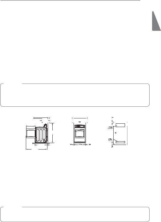
Clearances
14" max.* |
|
|
|
(7.6 cm) |
|
(35.6 cm) |
|
|
|
|
|
21 1⁄4" |
|
|
|
|
|
(54 cm) |
|
|
|
|
|
|
45 7 |
" |
|
|
|
|
|
⁄16 |
|
|
|
|
(115.3 cm) |
|
|
|
|
28 15⁄16" |
5"** |
(2.54 cm) |
(68.6 cm) |
(2.54 cm) |
|
(73.4 cm) |
(12.7 cm) |
Closet Door Vent |
|||
50 1⁄4" |
|
|
|
(7.6 cm) |
Requirements |
(127.5 cm) |
|
|
|
|
|
Installation Spacing For Recessed Area Or Closet Installation
The following spacing dimensions are recommended for this dryer. This dryer has been tested for spacing of
JODIFT DN DMFBSBODF PO UIF TJEFT BOE SFBS 3FDPNNFOEFE TQBDJOH TIPVME CF DPOTJEFSFE GPS UIF GPMMPXJOH reasons:
t "EEJUJPOBM TQBDJOH TIPVME CF DPOTJEFSFE GPS FBTF PG |
t "EEJUJPOBM TQBDJOH TIPVME CF DPOTJEFSFE PO BMM TJEFT |
installation and servicing. |
of the dryer to reduce noise transfer. |
t "EEJUJPOBM DMFBSBODFT NJHIU CF SFRVJSFE GPS XBMM EPPS |
For closet installation, with a door, minimum |
and floor moldings. |
ventilation openings in the top and bottom of the |
|
door are required. Louvered doors with equivalent |
|
ventilation openings are acceptable. |
|
t $PNQBOJPO BQQMJBODF TQBDJOH TIPVME BMTP CF |
|
considered. |
 NOTE
NOTE
ENGLISH
5IFSF TIPVME CF BU MFBTU B MJUUMF TQBDF BSPVOE UIF ESZFS PS BOZ PUIFS BQQMJBODF UP FMJNJOBUF UIF USBOTGFS PG vibration from one to the other. Too much vibration, it could cause them to make noise or touch each other causing paint damage and making even more noise.
14 INSTALLATION INSTRUCTIONS
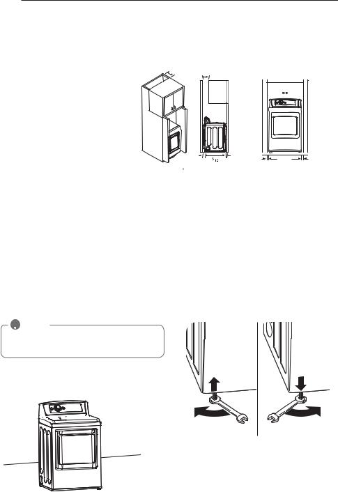
Clearances (cont.)
Recommended Installation Spacing For Cabinet Installation
t For cabinet installation with a door, minimum ventilation openings in the top of the cabinet are required.
*Required spacing
**For side or bottom venting,
JODIFT DN TQBDJOH JT BMMPXFE
Leveling the Dryer
7"* (17.8 cm) |
7"* (17.8 cm) |
|
5"* |
28 |
1"* |
(12.7 cm) (73.4 cm) (2.5 cm) |
||
1" |
27" |
1" |
(2.54 cm) (68.6 cm) |
(2.54 cm) |
WWARNING
t 5P SFEVDF UIF SJTL PG JOKVSZ UP QFSTPOT BEIFSF UP BMM JOEVTUSZ SFDPNNFOEFE TBGFUZ QSPDFEVSFT JODMVEJOH UIF VTF PG MPOH TMFFWFE HMPWFT BOE TBGFUZ HMBTTFT
Failure to follow this warning can cause serious injury or death.
t 5IF BQQMJBODFT BSF IFBWZ 5XP PS NPSF QFPQMF BSF SFRVJSFE XIFO JOTUBMMJOH UIF ESZFS Failure to follow this warning can cause serious injury or death.
To ensure that the dryer provides optimal drying performance, it must be level. To minimize vibration, noise, and unwanted movement, the floor must be a perfectly level, solid surface.
t "MM GPVS MFWFMJOH GFFU NVTU SFTU TPMJEMZ PO UIF GMPPS
Gently push on the top corners of the dryer to make sure that the dryer does not rock from corner to corner.
If you are installing the dryer on the optional pedestal, you must use the leveling feet on the pedestal to level the dryer. The dryer leveling feet should be fully retracted.
6TF BO BEKVTUBCMF XSFODI UP UVSO UIF MFWFMJOH GFFU
Turn clockwise to raise the dryer or counterclockwise to lower it. Raise or lower the leveling feet until dryer is level from side to side and front to back.
.BLF TVSF UIBU BMM MFWFMJOH GFFU BSF JO GJSN DPOUBDU XJUI the floor.
 NOTE
NOTE
Adjust the leveling feet only as far as necessary to level the dryer. Extending the leveling feet more than necessary can cause the dryer to vibrate.
1PTJUJPO UIF ESZFS JO UIF GJOBM MPDBUJPO 1MBDF B MFWFM across the top of the dryer.


 Level
Level
 Leveling Feet
INSTALLATION INSTRUCTIONS 15
Reversing the Door
#FGPSF ZPV CFHJO
 NOTE
NOTE
The door reversal procedure for the two-way door is far more complex than for a conventional dryer
door. It is recommended that you read through these instructions in their entirety before beginning the process, in order to gauge whether you prefer to have the procedure done by a professional installer or service person.
The door reversal procedure consists of four main parts:
3FNPWJOH BOE SFJOTUBMMJOH UIF EPPS BOE IJOHFT TUFQTBOE3FNPWJOH BOE SFWFSTJOH DPNQPOFOUT PO UIF ESZFS DBCJOFU TUFQ3FNPWJOH BOE SFWFSTJOH DPNQPOFOUT PO UIF door DPWFS TUFQT BOE3FNPWJOH BOE SFWFSTJOH DPNQPOFOUT inside the door
TUFQT UISPVHI
5PPMT 3FRVJSFE t 1IJMMJQT TDSFXESJWFS
t -BSHF GMBU CMBEF TDSFXESJWFS SFDPNNFOEFE GPS IJOHF screws if they are tight or your Phillips screwdriver is
XPSO
t 4NBMM GMBU CMBEF TDSFXESJWFS GPS MJGUJOH PVU QBSUT
WWARNING
t5P BWPJE EBNBHF UP UIF ESZFS PS UIF EPPS TVQQPSU UIF EPPS XJUI B TUPPM PS CPY UIBU GJUT VOEFS UIF EPPS PS IBWF BO BTTJTUBOU TVQQPSU UIF XFJHIU PG UIF EPPS
t "WPJE ESPQQJOH UIF EPPS UP BWPJE EBNBHF UP UIF EPPS PS UIF GMPPS
t 6OQMVH UIF ESZFS PS UVSO PGG QPXFS BU UIF NBJO DJSDVJU CSFBLFS CFGPSF CFHJOOJOH EPPS SFWFSTBM
t5)& %3:&3 %003 *47&3: -"3(& "/% )&"7: 'BJMVSF UP GPMMPX UIF JOTUSVDUJPOT CFMPX DBO SFTVMU JO EBNBHF UP UIF ESZFS QSPQFSUZ EBNBHF PS QFSTPOBM JOKVSZ
*OTUSVDUJPOT
 NOTE
NOTE
The instructions here are for changing the door swing from a right to a left side hinge. If the door has been reversed, and it is necessary to change it back, use care when following these instructions. Some of
the illustrations and the left/right references will be reversed, and you will need to read the instructions carefully.
WWARNING
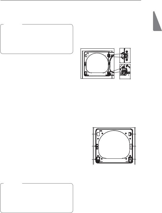
#F TVSF UP TVQQPSU UIF XFJHIU PG UIF EPPS CFGPSF removing the hinge screws.
0QFO UIF EPPS GSPN UIF TJEF TP UIBU UIF IJOHF TDSFXT BSF BDDFTTJCMF
Two large screws
Two small screws
3FNPWF UIF GPVS IJOHF TDSFXT
While supporting the door, remove the four hinge screws, two from each hinge. Set the door aside face down on a protected surface to prevent damage to the door or the work surface.
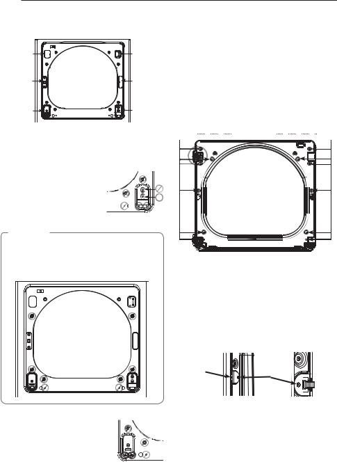
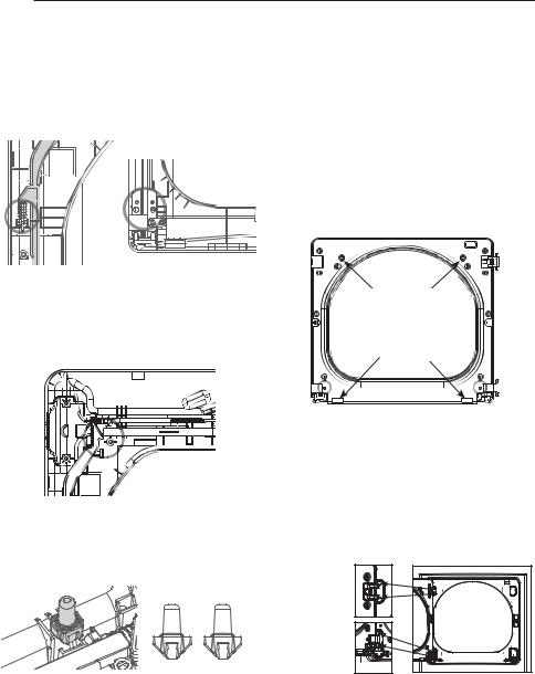
3FWFSTF UIF DPNQPOFOUT PO UIF DBCJOFU
a.Use a Phillips screwdriver to remove the two screws and the latch mechanism on the front panel of the cabinet.
hinge |
upper |
|
cover |
hinge |
|
latch |
latch hole |
|
mechanism |
cover |
|
hinge |
hinge |
|
bracket |
||
|
b.Remove the latch hole cover by gently prying it up with a flat blade screwdriver, being careful not to scratch the paint. Install the latch hole cover on the opposite side, where the latch mechanism was
removed. Install the latch mechanism in the position from which you removed the latch hole cover, using the two screws removed in step a.
c.Remove the hinge cover by gently prying it up with a flat blade screwdriver, being careful not to scratch
UIF QBJOU 3PUBUF UIF IJOHF DPWFS EFHSFFT BOE install it on the opposite side, where the upper hinge was attached.
ENGLISH
16 INSTALLATION INSTRUCTIONS
Reversing the Door (continued)
hinge |
upper |
|
cover |
hinge |
|
latch |
latch hole |
|
mechanism |
cover |
|
hinge |
hinge |
|
bracket |
||
|
d.Reverse the hinge and the hinge bracket at the bottom of the cabinet. Remove the two screws from the hinge bracket at bottom right and remove the hinge bracket.
Remove the lower of the two screws behind the hinge bracket. Do NOT remove the upper screw behind the hinge bracket. Set the parts aside.
 NOTE
NOTE
Do /05 remove any of the eight screws on the face of
UIF DBCJOFU NBSLFE XJUI CFMPX %PJOH TP DPVME result in damage to the dryer and the need for a service call to repair the dryer.
e. Remove the three screws on the hinge at bottom left. Remove the hinge and reinstall it on the right side. The top screw occupies the hole where you removed the screw behind the hinge bracket in step d.
f.Install the hinge bracket removed in step d on the bottom left side, first installing one screw behind the hinge bracket.
ON THE DOOR:
-JGU PGG UIF EPPS DPWFS
With the door laid inside facing up on a protected
TVSGBDF SFNPWF UIF TDSFXT PO UIF JOTJEF PG UIF door. Carefully lift off the door cover with the help of a small flat blade screwdriver inserted in the upper
DPSOFS DJSDMFE CFMPX
WWARNING
The edges of the door cover may be sharp. Take care when handling, or wear gloves to avoid injury.
twelve screws
4XJUDI UIF EPPS TUSJLF BOE UIF CMBOL DPWFS
Remove the four screws on the door cover that secure the door strike and the blank cover.
Switch the door strike and the blank cover, installing them on the opposite sides from which they were removed.
Set the door cover aside.
long screw |
short |
|
screws |
||
|
||
blank cover |
door strike |
3FWFSTF UIF DPNQPOFOUT JOTJEF UIF EPPS
You will now be removing and reversing various
DPNQPOFOUT JOTJEF UIF EPPS 3FGFS UP QBHF GPS a detailed diagram and identification of the inner
TUSVDUVSF BOE QBSUT PG UIF EPPS 5IF EJBHSBN TIPXT the “before view” of the door, with the default setup for a right side hinge swing. After following these instructions, your door should be a mirror image of
UIF JMMVTUSBUJPO
INSTALLATION INSTRUCTIONS 17
Reversing the Door (continued)
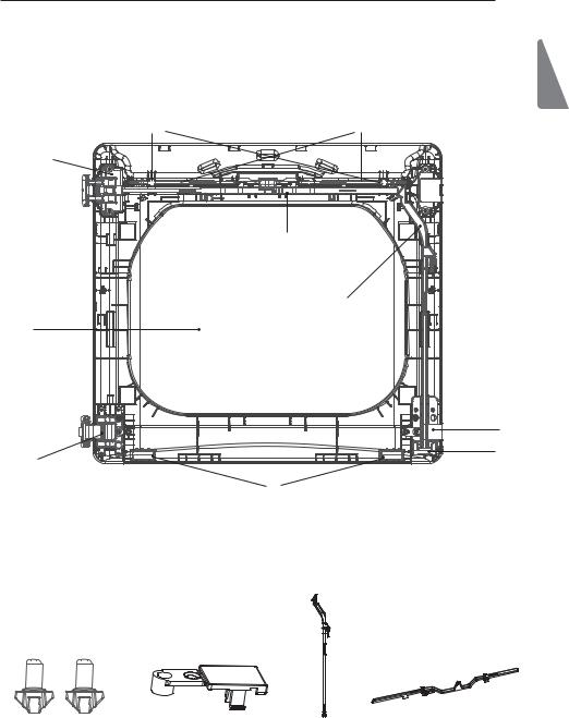
Inner Structure of Door (before reversing - right hinge swing)
interlock buttons |
inner lock rods |
upper hinge assembly


 upper hinge upper hinge


 filler pivot


top lock rod
side lock rod
glass
|
lower hinge |
|
filler |
lower |
lower |
hinge |
hinge |
assembly |
bracket |
|
bumpers |
ENGLISH
interlock buttons |
lower hinge filler |
side lock rod |
top lock rod |
18 INSTALLATION INSTRUCTIONS
Reversing the Door (continued)
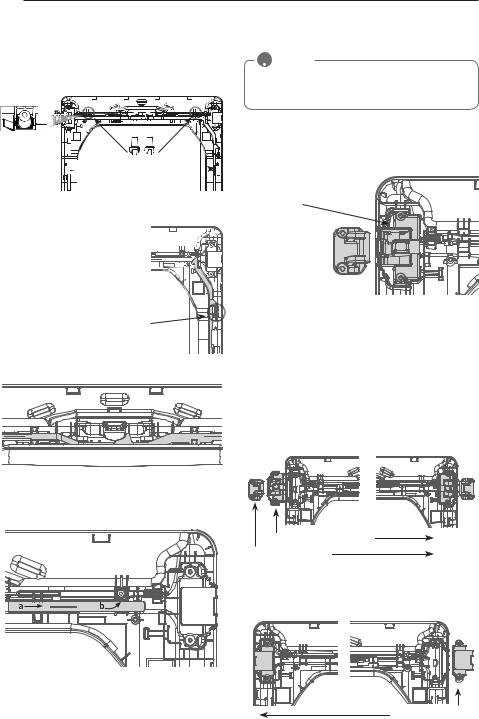
-JGU PVU UIF UXP HSFZ JOUFSMPDL CVUUPOT
Lift out the two grey interlock buttons from the top of the outer door and set them aside for later use.
interlock buttons
side lock rod 
3FNPWF UIF TJEF MPDL SPE
Remove the side lock rod from the lower hinge bracket by lifting the top end of the rod and sliding it toward the top of the door. The spring should remain attached to the lock rod. Set the lock rod aside.
Spring
3FNPWF UIF UPQ MPDL SPE
a.Slide the lock rod to the right to remove it from the hinge assembly on the left side.
 NOTE
NOTE
%P OPU SFNPWF UIF UXP JOOFS MPDL SPET TFF QBHF located underneath the top lock rod. They do NOT need to be reversed
3FNPWF UIF VQQFS IJOHF QJWPU
Once the top lock rod has been removed, the hinge pivot can easily be removed from the hinge assembly on the upper left and set aside.
upper hinge assembly
upper hinge  pivot
pivot
3FWFSTF UIF VQQFS IJOHF BTTFNCMZ BOE IJOHF GJMMFS
-JGU PVU UIF VQQFS IJOHF GJMMFS PO UIF SJHIU BOE TFU JU aside.
$BSFGVMMZ MJGU UIF VQQFS IJOHF BTTFNCMZ PO UIF MFGU out of the outer door frame, using a small flat blade screwdriver if necessary. Rotate the hinge assembly
EFHSFFT BOE JOTUBMM JU PO UIF VQQFS SJHIU TJEF PG the outer door. You will need to press firmly to install the hinge assembly.
5IF IJOHF QJWPU SFNPWFE JO TUFQ XJMM CF JOTUBMMFE later.
upper hinge assembly
upper hinge pivot
/PX SPUBUF UIF IJOHF GJMMFS EFHSFFT BOE JOTUBMM JU on the upper left side of the door.
b.While sliding the lock rod right, lift the right end up and out of the guides.
upper hinge filler

INSTALLATION INSTRUCTIONS 19
Reversing the Door (continued)
3FJOTUBMM UIF UPQ MPDL SPE
3PUBUF UIF UPQ MPDL SPE SFNPWFE JO TUFQ degrees end for end from its original position and reinstall it. The longer leg will now be to the right of center.
a.Insert the right end of the lock rod into the right hinge assembly. Make sure the rod is aligned with the guides in the door panel.
b.Lower the rod into position, sliding it to bypass the center handle, making sure to align the lock rod with the guides all the way across the door panel. When released, the lock rod should slide completely into the hinge assembly on the right. Slide the
lock rod back and forth to make sure it is correctly positioned in the guides and slides easily.
*OTUBMM UIF UPQ SJHIU IJOHF QJWPU
Slide the upper lock rod left and place the top right hinge pivot in the hinge assembly. When the rod is released, it should lock the hinge pivot in place.
3FWFSTF UIF MPXFS IJOHF CSBDLFU BOE IJOHF BTTFNCMZ
a.3FNPWF UIF TDSFX GSPN UIF MPXFS IJOHF CSBDLFU PO UIF SJHIU BOE MJGU UIF IJOHF CSBDLFU PVU 4FU JU BTJEF
Remove the two screws from the lower hinge assembly on the bottom left and lift the hinge assembly out.
C 3PUBUF UIF MPXFS IJOHF BTTFNCMZ EFHSFFT BOE install it on the right side using the two screws removed in step a.
screws |
lower hinge assembly
c.Flip over the lower hinge bracket and release the tabs on the back locking the hinge filler to the hinge bracket.
taps 


E 3PUBUF UIF IJOHF GJMMFS EFHSFFT BOE TOBQ JU CBDL onto the FRONT of the hinge bracket facing in the opposite direction.
e.Mount the lower hinge bracket and the filler on the left side of the door with the screw removed in step a.
screw
ENGLISH
20 INSTALLATION INSTRUCTIONS
Reversing the Door (continued)
*OTUBMM UIF TJEF MPDL SPE
Flip the side lock rod over and install it on the opposite side. Insert the lower end into the left hinge and lower the rod into the guides on the door while compressing the spring inside the recess.
3FJOTUBMMUIFEPPSDPWFS
Clean the glass on the door and door cover, if necessary. Make sure the two gray interlock buttons are properly installed and that the top and side lock rods are properly aligned where they meet. Carefully lower the door cover into place, aligning the holes in the cover with the interlock buttons on the top and the bumpers on the bottom. Take care not to dislodge the lock rods while mounting the door cover. Once the door cover is
JO QMBDF TFDVSF JU XJUI UIF TDSFXT SFNPWFE JO TUFQ
The ten similar screws go around the top and sides of the door cover. Make sure to install the two different screws on the bottom edge, in the locations marked below
Make sure the top of the side lock rod is beside the top lock rod and the two do not overlap each other, so the two rods can interact correctly. If they are not aligned properly, the door will not operate properly.
interlock buttons
bumpers
3FJOTUBMM UIF JOUFSMPDL CVUUPOT
Reinstall the two gray interlock buttons removed in
TUFQ POF PO FBDI TJEF PG UIF PVUFS EPPS QBOFM
WWARNING
#F TVSF UP TVQQPSU UIF XFJHIU PG UIF EPPS CFGPSF JOTUBMMJOH the hinge screws.
3FJOTUBMMUIFEPPS
While supporting the door, install the four hinge screws
SFNPWFE JO TUFQ 5FTU UIF TXJOH PG UIF EPPS UP NBLF sure the hinges and latch are properly aligned and that the door opens, closes and latches properly in both directions.
Two large screws
Two small screws
If the door doesn’t operate smoothly, remove the door and then the door cover to check that the lock rods and interlock buttons are properly mounted and aligned.
The interlock buttons should be oriented correctly and operating smoothly. The interlock rods should be in the proper position and should not overlap at the contact
QPJOU 4FF TUFQT
If the door is damaged, or if the door does not work after
SFBTTFNCMZ DPOUBDU UIF DBMM DFOUFS BU
Installing the Side Vent Kit
WWARNING
t 6TF B IFBWZ NFUBM WFOU t %P OPU VTF QMBTUJD PS UIJO GPJM EVDU t $MFBO PME EVDUT CFGPSF JOTUBMMJOH UIJT ESZFS
t5P SFEVDF UIF SJTL PG JOKVSZ UP QFSTPOT BEIFSF UP BMM JOEVTUSZ SFDPNNFOEFE TBGFUZ QSPDFEVSFT JODMVEJOH UIF VTF PG MPOH TMFFWFE HMPWFT BOE TBGFUZ HMBTTFT
t Failure to follow all of the safety warnings in this manual could result in property damage, injury to persons, or death.
Your new dryer is shipped to vent to the rear. It can also
CF DPOGJ HVSFE UP WFOU UP UIF CPUUPN PS TJEF SJHIU TJEF WFOUJOH JT OPU BWBJMBCMF PO HBT NPEFMT
"O BEBQUFS LJU QBSU OVNCFS &&- # NBZ CF purchased from your LG retailer. This kit contains the necessary duct components to change the dryer vent location.
3FNPWF UIF SFBS FYIBVTU EVDU SFUBJOJOH TDSFX 1VMM out the exhaust duct.
Retaining
Screw
Rear 
Exhaust Duct
015*0/ 4*%&7&/5*/(
1SFTT UIF UBCT PO UIF LOPDLPVU BOE DBSFGVMMZ SFNPWF UIF LOPDLPVU GPS UIF EFTJSFE WFOU PQFOJOH SJHIU TJEF WFOUJOH JT OPU BWBJMBCMF PO HBT NPEFMT 1SFTT UIF adapter duct onto the blower housing and secure to the base of the dryer as shown.
Adapter
Duct
#SBDLFU 
 ,OPDLPVU
INSTALLATION INSTRUCTIONS 21
1SFBTTFNCMF B JODIFT DN FMCPX UP UIF OFYUJODIFT DN EVDU TFDUJPO BOE TFDVSF BMM KPJOUT XJUI EVDU UBQF #F TVSF UIBU UIF NBMF FOE PG UIF elbow faces AWAY from the dryer. Insert the elbow/ duct assembly through the side opening and press it onto the adapter duct. Secure in place with duct tape.
#F TVSF UIBU UIF NBMF FOE PG UIF EVDU QSPUSVEFT JODIFT DN UP DPOOFDU UIF SFNBJOJOH EVDUXPSL
Attach cover plate to the back of the dryer with included screw.
Cover
Plate
Elbow |
” |
|
DN |
015*0/ #0550.7&/5*/(
1SFTT UIF BEBQUFS EVDU POUP UIF CMPXFS IPVTJOH BOE secure to the base of the dryer as shown.
Adapter
Duct
#SBDLFU
*OTFSU UIF JODIFT DN FMCPX UISPVHI UIF SFBS PQFOJOH BOE QSFTT JU POUP UIF BEBQUFS EVDU #F TVSF that the male end of the elbow faces down through hole in the bottom of the dryer. Secure in place with duct tape. Attach the cover plate to the back of the dryer with included screw.
Cover
Plate
Elbow
ENGLISH

22 INSTALLATION INSTRUCTIONS
Venting the Dryer
WWARNING
To reduce the risk of fire, electric shock, or injury to persons when using this appliance, follow basic precautions, including the following:
t %P OPU DSVTI PS DPMMBQTF EVDUXPSL Failure to follow these instructions can result in fire or death.
t %P OPU BMMPX EVDUXPSL UP SFTU PO PS DPOUBDU TIBSQ PCKFDUT Failure to follow these instructions can result in fire or death.
t *G DPOOFDUJOH UP FYJTUJOH EVDUXPSL NBLF TVSF JU JT TVJUBCMF BOE DMFBO CFGPSF JOTUBMMJOH UIF ESZFS
Failure to follow these instructions can result in fire or death.
t 7FOUJOH NVTU DPOGPSN UP MPDBM CVJMEJOH DPEFT
Failure to follow these instructions can result in fire or death.
t (BT ESZFST .645 FYIBVTU UP UIF PVUEPPST Failure to follow these instructions can result in fire or death.
t 6TF POMZ JODI DN SJHJE PS GMFYJCMF NFUBM EVDUXPSL JOTJEF UIF ESZFS DBCJOFU BOE GPS WFOUJOH PVUTJEF Failure to follow these instructions can result in fire or death.
t 5P SFEVDF UIF SJTL PG GJSF DPNCVTUJPO PS BDDVNVMBUJPO PG DPNCVTUJCMF HBTFT %0 /05 FYIBVTU ESZFS BJS JOUP BO FODMPTFE BOE VOWFOUJMBUFE BSFB TVDI BT BO BUUJD XBMM DFJMJOH DSBXM TQBDF DIJNOFZ HBT WFOU PS DPODFBMFE TQBDF PG B CVJMEJOH
Failure to follow these instructions can result in fire or death.
t 5P SFEVDF UIF SJTL PG GJSF %0 /05 FYIBVTU UIF ESZFS XJUI QMBTUJD PS UIJO GPJM EVDUJOH Failure to follow these instructions can result in fire or death.
t 5IF FYIBVTU EVDU NVTU CF JODIFT DN JO EJBNFUFS XJUI OP PCTUSVDUJPOT 5IF FYIBVTU EVDU TIPVME CF LFQU BT TIPSU BT QPTTJCMF .BLF TVSF UP DMFBO BOZ PME EVDUT CFGPSF JOTUBMMJOH ZPVS OFX ESZFS Failure to follow these instructions can result in fire or death.
t 3JHJE PS TFNJSJHJE NFUBM EVDUJOH JT SFDPNNFOEFE GPS VTF CFUXFFO UIF ESZFS BOE UIF XBMM *O TQFDJBM JOTUBMMBUJPOT XIFO JU JT JNQPTTJCMF UP NBLF B DPOOFDUJPO XJUI UIF BCPWF SFDPNNFOEBUJPOT B 6- MJTUFE GMFYJCMF NFUBM USBOTJUJPO EVDU NBZ CF VTFE CFUXFFO UIF ESZFS BOE XBMM DPOOFDUJPO POMZ 5IF VTF PG UIJT EVDUJOH XJMM BGGFDU ESZJOH UJNF Failure to follow these instructions can result in fire or death.
t %0 /05 VTF TIFFU NFUBM TDSFXT PS PUIFS GBTUFOFST XIJDI FYUFOE JOUP UIF EVDU UIBU DPVME DBUDI MJOU BOE SFEVDF UIF FGGJ DJFODZ PG UIF FYIBVTU TZTUFN 4FDVSF BMM KPJOUT XJUI EVDU UBQF Failure to follow these instructions can result in fire or death.
t %VDUXPSL JT OPU QSPWJEFE XJUI UIF ESZFS :PV TIPVME PCUBJO UIF OFDFTTBSZ EVDUXPSL MPDBMMZ 5IF FOE DBQ TIPVME IBWF IJOHFE EBNQFST UP QSFWFOU CBDLESBGU XIFO UIF ESZFS JT OPU JO VTF Failure to follow these instructions can result in fire or death.
t 5IF UPUBM MFOHUI PG GMFYJCMF NFUBM EVDU TIBMM OPU FYDFFE GU N
t *O $BOBEB POMZ UIPTF GPJM UZQF GMFYJCMF EVDUT JG BOZ TQFDJGJDBMMZ JEFOUJGJFE GPS VTF XJUI UIF BQQMJBODF CZ UIF NBOVGBDUVSFS TIBMM CF VTFE In the United States, only those foil-type flexible ducts, if any, specifically identified for use with the appliance by the manufacturer and that comply with the Outline for Clothes Dryer Transition Duct, Subject 2158A, shall be used.
|
|
|
INSTALLATION INSTRUCTIONS |
23 |
Venting the Dryer (cont.) |
|
ENGLISH |
||
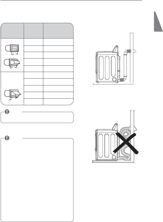
Ductwork |
/VNCFS 0G |
.BYJNVN-FOHUI 0G |
$PSSFDU 7FOUJOH |
|
|
|
|
|
|
8BMM $BQ 5ZQF |
¡ &MCPXT |
JODI%JBNFUFS |
|
|
|
|
3JHJE .FUBM%VDU |
|
|
Recommended |
|
GU N |
|
|
|
|
GU N |
|
|
w |
|
GU N |
|
|
DN |
|
|
||
|
|
GU N |
|
|
w |
|
GU N |
|
|
DN |
|
|
||
Use only for |
|
GU N |
|
|
short run |
|
GU N |
|
|
installations |
|
|
||
|
|
GU N |
|
|
|
|
GU N |
|
|
/ ” |
|
|
|
|
DN |
GU N |
|
|
|
|
*ODPSSFDU 7FOUJOH |
|
||
|
|
|
|
|
NOTE |
|
|
|
|
%FEVDU GU N GPS FBDI BEEJUJPOBM FMCPX *U JT OPU |
|
|
||
SFDPNNFOEFE UP VTF NPSF UIBO GPVS ¡ FMCPXT |
|
|
||
Routing and Connecting Ductwork |
|
|
||
NOTE |
|
|
|
|
Follow the guidelines below to maximize drying |
|
|
||
performance and reduce lint buildup and |
|
|
||
condensation in the ductwork. |
|
|
|
|
Ductwork and fittings are NOT included and must be |
|
|
||
purchased separately. |
|
|
|
|
t 6TF JODI DN EJBNFUFS SJHJE PS TFNJSJHJE |
|
|
||
metal ductwork. |
|
|
|
|
t 5IF FYIBVTU EVDU SVO TIPVME CF BT TIPSU BT QPTTJCMF t 6TF BT GFX FMCPX KPJOUT BT QPTTJCMF
t 5IF NBMF FOE PG FBDI TFDUJPO PG FYIBVTU EVDU NVTU point away from the dryer.
t 6TF EVDU UBQF PO BMM EVDU KPJOUT
t *OTVMBUF EVDUXPSL UIBU SVOT UISPVHI VOIFBUFE BSFBT in order to reduce condensation and lint buildup on duct surfaces.
t *ODPSSFDU PS JOBEFRVBUF FYIBVTU TZTUFNT BSF OPU covered by the dryer warranty. Failures or poor performance caused by such exhaust systems will not be covered by the dryer warranty.

24 INSTALLATION INSTRUCTIONS
Connecting Gas Dryers
WWARNING
To reduce the risk of fire, electric shock, or injury to persons when using this appliance, follow basic precautions, including the following:
t(BT TVQQMZ SFRVJSFNFOUT
"T TIJQQFE GSPN UIF GBDUPSZ UIJT ESZFS JT DPOGJHVSFE GPS VTF XJUI OBUVSBM HBT *U DBO CF DPOWFSUFE GPS VTF XJUI -1 -JRVFGJFE 1SPQBOF HBT (BT QSFTTVSF NVTU OPU FYDFFE JODIFT PG XBUFS DPMVNO
t" RVBMJGJFE TFSWJDF PS HBT DPNQBOZ UFDIOJDJBO NVTU
DPOOFDU UIF ESZFS UP UIF HBT TFSWJDF
Failure to do so can result in fire, explosion, or death.
t*TPMBUF UIF ESZFS GSPN UIF HBT TVQQMZ TZTUFN CZ
DMPTJOH JUT JOEJWJEVBM NBOVBM TIVUPGG WBMWF EVSJOH BOZ QSFTTVSF UFTUJOH PG UIF HBT TVQQMZ Failure to do so can result in fire, explosion, or death.
t4VQQMZ MJOF SFRVJSFNFOUT
:PVS MBVOESZ SPPN NVTU IBWF B SJHJE HBT TVQQMZ MJOF UP ZPVS ESZFS *O UIF 6OJUFE 4UBUFT BO JOEJWJEVBM NBOVBM TIVUPGG WBMWF .645 CF JOTUBMMFE XJUIJO BU MFBTU GU N PG UIF ESZFS JO BDDPSEBODF XJUI UIF /BUJPOBM 'VFM (BT $PEF "/4* ; PS $BOBEJBO HBT JOTUBMMBUJPO DPEF $4" B149.1. A 1cľ JODI /15 QJQF QMVH NVTU CF JOTUBMMFE
Failure to do so can result in fire, explosion, death.
t*G VTJOH B SJHJE QJQF UIF SJHJE QJQF TIPVME CF
JODI *14 *G BDDFQUBCMF VOEFS MPDBM DPEFT BOE PSEJOBODFT BOE XIFO BDDFQUBCMF UP ZPVS HBT TVQQMJFS 3cľ JODI BQQSPWFE UVCJOH NBZ CF VTFE XIFSF MFOHUIT BSF MFTT UIBO GU N -BSHFS UVCJOH TIPVME CF VTFE GPS MFOHUIT JO FYDFTT PG GUN Failure to do so can result in fire, explosion, or death.
Electrical requirements for gas models only
WWARNING
t$POOFDU UIF ESZFS UP UIF UZQF PG HBT TIPXO PO UIF OBNFQMBUF Failure to do so can result in fire, explosion, or death.
t5P QSFWFOU DPOUBNJOBUJPO PG UIF HBT WBMWF
QVSHF UIF HBT TVQQMZ PG BJS BOE TFEJNFOU CFGPSF DPOOFDUJOH UIF HBT TVQQMZ UP UIF ESZFS #FGPSF UJHIUFOJOH UIF DPOOFDUJPO CFUXFFO UIF HBT TVQQMZ BOE UIF ESZFS QVSHF SFNBJOJOH BJS VOUJM UIF PEPS PG HBT JT EFUFDUFE Failure to do so can result in fire, explosion, or death.
t%0 /05 VTF BO PQFO GMBNF UP JOTQFDU GPS HBT MFBLT 6TF B OPODPSSPTJWF MFBL EFUFDUJPO GMVJE Failure to do so can result in fire, explosion, or death.
t6TF POMZ B OFX "(" PS $4" DFSUJGJFE HBT TVQQMZ MJOF XJUI GMFYJCMF TUBJOMFTT TUFFM DPOOFDUPST Failure to do so can result in fire, explosion, or death.
t4FDVSFMZ UJHIUFO BMM HBT DPOOFDUJPOT Failure to do so can result in fire, explosion, or death.
t%0 /05 BUUFNQU BOZ EJTBTTFNCMZ PG UIF ESZFS
BOZ EJTBTTFNCMZ SFRVJSFT UIF BUUFOUJPO BOE UPPMT PG BO BVUIPSJ[FE BOE RVBMJGJFE TFSWJDF QFSTPO PS DPNQBOZ Failure to do so can result in fire, explosion, or death.
t6TF B QJQF KPJOU DPNQPVOE UIBU JT JOTPMVCMF JO
-JRVFGJFE 1FUSPMFVN -1 HBT PO BMM QJQF UISFBET
Failure to do so can result in fire, explosion, or death.
To reduce the risk of fire, electric shock, or injury to persons when using this appliance, follow basic precautions, including the following:
t%P OPU VOEFS BOZ DJSDVNTUBODFT DVU PS SFNPWF UIF UIJSE HSPVOE QSPOH GSPN UIF QPXFS DPSE Failure to follow this warning can result in fire, explosion, or death.
t'PS QFSTPOBM TBGFUZ UIJT ESZFS NVTU CF QSPQFSMZ HSPVOEFE Failure to follow this warning can result in fire, explosion, or death.
t5IF QPXFS DPSE PG UIJT ESZFS JT FRVJQQFE XJUI
B QSPOH HSPVOEJOH QMVH XIJDI NBUFT XJUI B TUBOEBSE QSPOH HSPVOEJOH XBMM PVUMFU UP NJOJNJ[F UIF QPTTJCJMJUZ PG FMFDUSJD TIPDL IB[BSE GSPN UIJT BQQMJBODF Failure to follow this warning can result in fire, explosion, or death.
t5IJT ESZFS NVTU CF QMVHHFE JOUP B )[ 7"$
HSPVOEFE PVUMFU QSPUFDUFE CZ B BNQFSF GVTF PS DJSDVJU CSFBLFS Failure to follow this warning can result in fire, explosion, or death.
t8IFSF B TUBOEBSE QSPOH XBMM PVUMFU JT
FODPVOUFSFE JU JT ZPVS QFSTPOBM SFTQPOTJCJMJUZ BOE PCMJHBUJPO UP IBWF JU SFQMBDFE XJUI B QSPQFSMZ HSPVOEFE QSPOH XBMM PVUMFU Failure to follow this warning can result in fire, explosion, or death.
INSTALLATION INSTRUCTIONS 25
Connecting Gas Dryers (cont.)
WWARNING
To reduce the risk of fire, electric shock, or injury to persons when using this appliance, follow basic precautions, including the following:
t *OTUBMMBUJPO BOE TFSWJDF NVTU CF QFSGPSNFE CZ
B RVBMJGJFE JOTUBMMFS TFSWJDF BHFODZ PS UIF HBT TVQQMJFS Failure to do so can result in fire, explosion, or death.
t 6TF POMZ B OFX TUBJOMFTT TUFFM GMFYJCMF DPOOFDUPS BOE B OFX "(" DFSUJGJFE DPOOFDUPS Failure to do so can result in fire, explosion, or death.
t " HBT TIVUPGG WBMWF NVTU CF JOTUBMMFE XJUIJO GUN PG UIF ESZFS Failure to do so can result in fire, explosion, or death.
t 5IF ESZFS JT DPOGJHVSFE GPS /BUVSBM (BT XIFO
TIJQQFE GSPN UIF GBDUPSZ .BLF TVSF UIBU UIF ESZFS JT FRVJQQFE XJUI UIF DPSSFDU CVSOFS PSJGJDF GPS UIF UZQF PG HBT CFJOH VTFE /BUVSBM (BT PS -JRVFGJFE 1FUSPMFVN Failure to do so can result in fire, explosion, or death.
t *G OFDFTTBSZ UIF DPSSFDU PSJGJDF 'PS UIF -1 PSJGJDF
LJU PSEFS QBSU OVNCFS &&- % TIPVME CF JOTUBMMFE CZ B RVBMJGJFE UFDIOJDJBO BOE UIF DIBOHF TIPVME CF OPUFE PO UIF ESZFS Failure to do so can result in fire, explosion, or death.
t "MM DPOOFDUJPOT NVTU CF JO BDDPSEBODF XJUI MPDBM DPEFT BOE SFHVMBUJPOT. Failure to do so can result in fire, explosion, or death.
t (BT ESZFST .645 FYIBVTU UP UIF PVUEPPST Failure to do so can result in fire, explosion, or death.
Connecting the gas supply
.BLF TVSF UIBU UIF HBT TVQQMZ UP UIF MBVOESZ SPPN JT turned OFF. Confirm that the type of gas available in your laundry room is appropriate for the dryer. The dryer is prepared for Natural Gas with a ⁄8 - inch NPT gas connection.
3FNPWF UIF TIJQQJOH DBQ GSPN UIF HBT DPOOFDUJPO BU UIF CBDL PG UIF ESZFS #F DBSFGVM OPU UP EBNBHF the threads of the gas connector when removing the shipping cap.
$POOFDU UIF ESZFS UP ZPVS MBVOESZ SPPN T HBT TVQQMZ using a new flexible stainless steel connector with a ⁄8 - inch NPT fitting.
4FDVSFMZ UJHIUFO BMM DPOOFDUJPOT CFUXFFO UIF dryer and your laundry room’s gas supply. Turn on your laundry room’s gas supply and check all pipe
DPOOFDUJPOT CPUI JOUFSOBM BOE FYUFSOBM GPS HBT MFBLT with a noncorrosive leak-detection fluid.
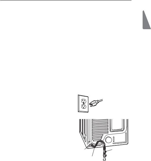
Electrical connection
w /15 (BT
Connection
AGA/CSA-Certified
Stainless Steel Flexible
Connector
Plug dryer into a 7"$)[ HSPVOEFE QSPOH outlet.
w /15 1JQF
Plug

 Gas Supply Shutoff Valve
High-altitude installations
5IF #56 SBUJOH PG UIJT ESZFS JT "(" DFSUJGJFE GPS FMFWBUJPOT CFMPX GFFU
If your gas dryer is being installed at an elevation above
GFFU JU NVTU CF EFSBUFE CZ B RVBMJGJFE UFDIOJDJBO or gas supplier.
ENGLISH

26 INSTALLATION INSTRUCTIONS
Connecting Electric Dryers
WWARNING
To help prevent fire, electric shock, serious injury, or death, the wiring and grounding must conform to the latest edition of the National Electrical Code,
"/4* /'1" BOE BMM BQQMJDBCMF MPDBM SFHVMBUJPOT
Please contact a qualified electrician to check your home’s wiring and fuses to ensure that your home has adequate electrical power to operate the dryer.
Electrical requirements for electric models only
WWARNING
To reduce the risk of fire, electric shock, or injury to persons when using this appliance, follow basic precautions, including the following:
t 5IJT ESZFS NVTU CF DPOOFDUFE UP B HSPVOEFE
NFUBM QFSNBOFOU XJSJOH TZTUFN PS BO FRVJQNFOU HSPVOEJOH DPOEVDUPS NVTU CF SVO XJUI UIF DJSDVJU DPOEVDUPST BOE DPOOFDUFE UP UIF FRVJQNFOU HSPVOEJOH UFSNJOBM PS MFBE PO UIF ESZFS Failure to do so can result in fire, explosion, or death.
t 5IF ESZFS IBT JUT PXO UFSNJOBM CMPDL UIBU NVTU
CF DPOOFDUFE UP B TFQBSBUF 7"$ )FSU[ TJOHMF QIBTF DJSDVJU GVTFE BU BNQFSFT UIF DJSDVJU NVTU CF GVTFE PO CPUI TJEFT PG UIF MJOF &-&$53*$"- 4&37*$& '03 5)& %3:&3 4)06-% #& 0' 5)& ."9*.6. 3"5& 70-5"(& -*45&% 0/ 5)& /".&1-"5& %0 /05 $0//&$5 %3:&3 5003 70-5 $*3$6*5 Failure to follow these instructions can result in fire, explosion, or death.
t *G CSBODI DJSDVJU UP ESZFS JT GU N PS MFTT JO
MFOHUI VTF 6- 6OEFSXSJUFST -BCPSBUPSJFT MJTUFE /P "8( XJSF DPQQFS XJSF POMZ PS BT SFRVJSFE CZ MPDBM DPEFT *G PWFS GU N VTF 6- MJTUFE /P "8( XJSF DPQQFS XJSF POMZ PS BT SFRVJSFE CZ MPDBM DPEFT "MMPX TVGGJDJFOU TMBDL JO XJSJOH TP ESZFS DBO CF NPWFE GSPN JUT OPSNBM MPDBUJPO XIFO OFDFTTBSZ Failure to do so can result in fire, explosion, or death.
t 5IF QPXFS DPSE QJHUBJM DPOOFDUJPO CFUXFFO
XBMM SFDFQUBDMF BOE ESZFS UFSNJOBM CMPDL *4 /05 TVQQMJFE XJUI ESZFS 5ZQF PG QJHUBJM BOE HBVHF PG XJSF NVTU DPOGPSN UP MPDBM DPEFT BOE XJUI JOTUSVDUJPOT PO UIF GPMMPXJOH QBHFT Failure to follow these instructions can result in fire, explosion, or death.
t " XJSF DPOOFDUJPO JT SFRVJSFE GPS BMM NPCJMF BOE
NBOVGBDUVSFE IPNF JOTUBMMBUJPOT BT XFMM BT BMM OFX DPOTUSVDUJPO BGUFS +BOVBSZ " XJSF DPOOFDUJPO NVTU CF VTFE XIFSF MPDBM DPEFT EP OPU QFSNJU HSPVOEJOH UISPVHI UIF OFVUSBM XJSF Failure to do so can result in fire, explosion, or death.
WWARNING
To reduce the risk of fire, electric shock, or injury to persons when using this appliance, follow basic precautions, including the following:
t %P OPU NPEJGZ UIF QMVH BOE JOUFSOBM XJSF QSPWJEFE XJUI UIF ESZFS
t 5IF ESZFS TIPVME CF DPOOFDUFE UP IPMF PVUMFU
t *G JU EPFT OPU GJU UIF PVUMFU B QSPQFS PVUMFU XJMM OFFE UP CF JOTUBMMFE CZ B RVBMJGJFE FMFDUSJDJBO
WWARNING
To reduce the risk of fire, electric shock, or injury to persons when using this appliance, follow basic precautions, including the following:
t "OZ JOTUBMMBUJPO JO B NBOVGBDUVSFE PS NPCJMF
IPNF NVTU DPNQMZ XJUI UIF .BOVGBDUVSFE )PNF $POTUSVDUJPO BOE 4BGFUZ 4UBOEBSET 5JUMF $'3 1BSU PS 4UBOEBSE $"/ $4" ; .) BOE MPDBM DPEFT BOE PSEJOBODFT
t " XJSF DPOOFDUJPO JT SFRVJSFE GPS BMM NPCJMF BOE
NBOVGBDUVSFE IPNF JOTUBMMBUJPOT BT XFMM BT BMM OFX DPOTUSVDUJPO BGUFS +BOVBSZ Failure to do so can result in fire, explosion, or death.
INSTALLATION INSTRUCTIONS 27
Connecting Electric Dryers (cont.)
USA only
WWARNING
t $POOFDU UIF QPXFS DPSE UP UIF UFSNJOBM CMPDL $POOFD UFBDI QPXFS DPSE XJSF UP UIF UFSNJOBM CMPDL TDSFX UIBU IBT UIF TBNF DPMPSFE XJSF 'PS FYBNQMF DPOOFDU UIF CMBDL QPXFS DPSE XJSF UP UIF UFSNJOBM CMPDL TDSFX XJUI UIF CMBDL XJSF 'BJMVSF UP GPMMPX UIFTF JOTUSVDUJPOT NBZ SFTVMU JO B TIPSU PWFSMPBE fire or death.
t (SPVOEJOH UISPVHI UIF OFVUSBM DPOEVDUPS JT
QSPIJCJUFE GPS OFX CSBODI DJSDVJU JOTUBMMBUJPOTNPCJMF IPNFT SFDSFBUJPOBM WFIJDMFT BOEBSFBT XIFSF MPDBM DPEFT QSPIJCJU HSPVOEJOH UISPVHI UIF OFVUSBM DPOEVDUPS
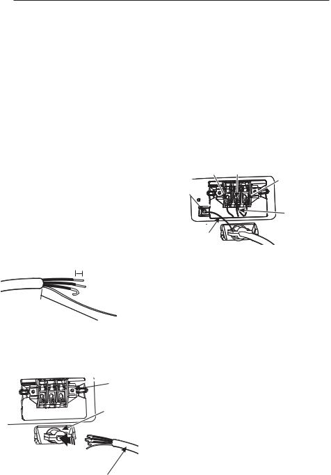
Four-wire connection for electric dryers:
Power cord
t " XJSF DPOOFDUJPO JT SFRVJSFE GPS BMM NPCJMF BOE manufactured home installations, as well as all new
DPOTUSVDUJPO BGUFS +BOVBSZ
t " 6- MJTUFE TUSBJO SFMJFG JT SFRVJSFE
3FNPWF UIF UFSNJOBM CMPDL BDDFTT DPWFS PO UIF VQQFS back of the dryer. Install a UL-listed strain relief into the power cord through-hole; then thread a UL-listed,
" 7 XJSF "8( NJOJNVN DPQQFS conductor power cord through the strain relief.
Terminal
#MPDL
UL-Listed
Strain Relief
UL-Listed
8JSF 1PXFS
Cord
t 6TF B " 7 6- MJTUFE QPXFS DPSE XJUI "8( NJOJNVN DPQQFS conductor and closed loop or forked terminals with upturned ends.
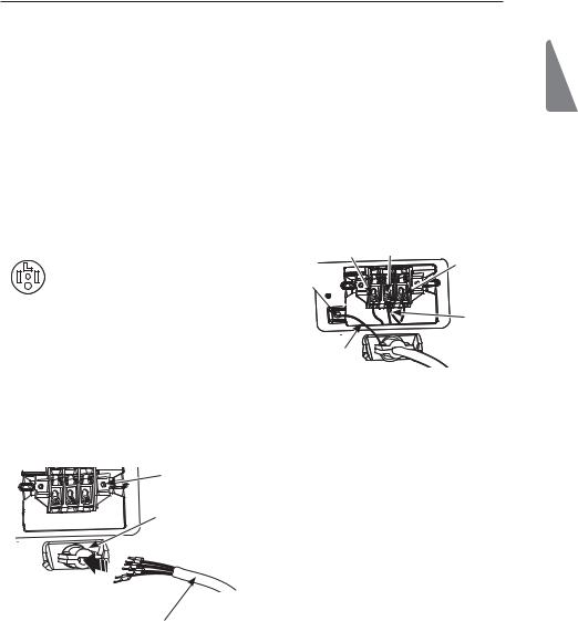
5SBOTGFS UIF ESZFS T HSPVOE XJSF GSPN CFIJOE UIF green ground screw to the center screw of the terminal block. Attach the two hot leads of the power cord to the outer terminal block screws. Attach the white neutral wire to the center terminal block screw. Attach the power cord ground wire to the green ground screw. 5*()5&/ "-- 4$3&84 4&$63&-:. Reinstall the terminal block access cover.
Hot |
Neutral |
|
#MBDL |
8IJUF |
|
Ground |
Hot |
|
3FE |
||
Screw |
||
|
||
|
White Wire |
|
|
moved from |
|
Power Cord |
Ground Screw |
|
|
||
Ground Wire |
|
ENGLISH
28 INSTALLATION INSTRUCTIONS
Connecting Electric Dryers (cont.) USA only
WWARNING
t $POOFDU UIF QPXFS DPSE UP UIF UFSNJOBM CMPDL $POOFDU FBDI QPXFS DPSE XJSF UP UIF UFSNJOBM CMPDL TDSFX UIBU IBT UIF TBNF DPMPSFE XJSF 'PS FYBNQMF DPOOFDU UIF CMBDL QPXFS DPSE XJSF UP UIF UFSNJOBM CMPDL TDSFX XJUI UIF CMBDL XJSF 'BJMVSF UP GPMMPX UIFTF JOTUSVDUJPOT NBZ SFTVMU JO B TIPSU PWFSMPBE GJSF PS EFBUI
t (SPVOEJOH UISPVHI UIF OFVUSBM DPOEVDUPS JT
QSPIJCJUFE GPS OFX CSBODI DJSDVJU JOTUBMMBUJPOTNPCJMF IPNFT SFDSFBUJPOBM WFIJDMFT BOEBSFBT XIFSF MPDBM DPEFT QSPIJCJU HSPVOEJOH UISPVHI UIF OFVUSBM DPOEVDUPS
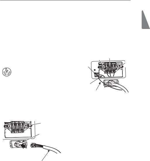
Four-wire connection for electric dryers: Direct wire
t " XJSF DPOOFDUJPO JT SFRVJSFE GPS BMM NPCJMF BOE manufactured home installations, as well as all new
DPOTUSVDUJPO BGUFS +BOVBSZ
t " 6- MJTUFE TUSBJO SFMJFG JT SFRVJSFE
3FNPWF JODIFT DN PG UIF PVUFS DPWFSJOH GSPN UIF XJSF 3FNPWF JODIFT PG JOTVMBUJPO GSPN UIF HSPVOE XJSF $VU PGG BQQSPYJNBUFMZ cĸ JODIFT DN GSPN UIF PUIFS UISFF XJSFT BOE TUSJQ JODI DN JOTVMBUJPO GSPN FBDI XJSF #FOE UIF FOET PG UIF UISFF shorter wires into a hook shape.
DN
Ground Wire
DN
3FNPWF UIF UFSNJOBM CMPDL BDDFTT DPWFS PO UIF VQQFS back of the dryer. Install a UL-listed strain relief into the power cord through-hole; then thread the power
DBCMF QSFQBSFE JO 4UFQ UISPVHI UIF TUSBJO SFMJFG
Terminal
#MPDL
UL-Listed
Strain Relief
t 6TF 6- MJTUFE XJSF "8( NJOJNVN DPQQFS conductor cable.
t "MMPX BU MFBTU GU N MFOHUI UP BMMPX GPS SFNPWBM and reinstallation of the dryer.
5SBOTGFS UIF ESZFS T HSPVOE XJSF GSPN CFIJOE UIF green ground screw to the center screw of the terminal block. Attach the two hot leads of the power cable to the outer terminal block screws. Attach the white neutral wire to the center terminal block screw. Attach the power cable ground wire to the green ground screw. 5*()5&/ "-- 4$3&84 4&$63&-:. Reinstall the terminal block access cover.
Hot |
Neutral |
|
#MBDL |
8IJUF |
|
Ground |
Hot |
|
3FE |
||
Screw |
||
|
||
|
White Wire |
|
|
moved from |
|
Power Cord |
Ground Screw |
|
|
||
Ground Wire |
|
6- -JTUFE 8JSF
Power Cord
INSTALLATION INSTRUCTIONS 29
Connecting Electric Dryers (cont.)
USA only
WWARNING
t $POOFDU UIF QPXFS DPSE UP UIF UFSNJOBM CMPDL $POOFDU FBDI QPXFS DPSE XJSF UP UIF UFSNJOBM CMPDL TDSFX UIBU IBT UIF TBNF DPMPSFE XJSF 'PS FYBNQMF DPOOFDU UIF CMBDL QPXFS DPSE XJSF UP UIF UFSNJOBM CMPDL TDSFX XJUI UIF CMBDL XJSF 'BJMVSF UP GPMMPX UIFTF JOTUSVDUJPOT NBZ SFTVMU JO B TIPSU PWFSMPBE GJSF PS EFBUI
t (SPVOEJOH UISPVHI UIF OFVUSBM DPOEVDUPS JT
QSPIJCJUFE GPS OFX CSBODI DJSDVJU JOTUBMMBUJPOTNPCJMF IPNFT SFDSFBUJPOBM WFIJDMFT BOEBSFBT XIFSF MPDBM DPEFT QSPIJCJU HSPVOEJOH UISPVHI UIF OFVUSBM DPOEVDUPS
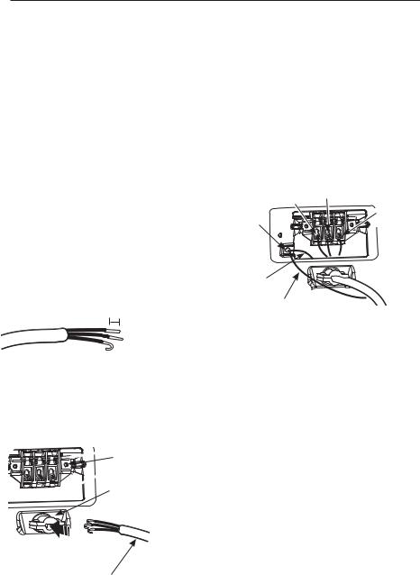
Three-wire connection for electric dryers: Power cord
t 6TF B " 7 6- MJTUFE QPXFS DPSE XJUI "8( NJOJNVN DPQQFS conductor and closed loop or forked terminals with upturned ends.
"UUBDI UIF UXP IPU MFBET PG UIF QPXFS DPSE UP UIF outer terminal block screws. Attach the neutral wire to the center terminal block screw. Connect the external
HSPVOE JG SFRVJSFE CZ MPDBM DPEFT UP UIF HSFFO ground screw. 5*()5&/ "-- 4$3&84 4&$63&-:. Reinstall the terminal block access cover.
|
Hot |
Neutral |
|
8IJUF |
|
|
#MBDL |
|
|
|
|
Ground |
|
Hot |
Screw |
|
3FE |
t " XJSF DPOOFDUJPO JT /05 QFSNJUUFE PO OFX DPOTUSVDUJPO BGUFS +BOVBSZ
t " 6- MJTUFE TUSBJO SFMJFG JT SFRVJSFE
3FNPWF UIF UFSNJOBM CMPDL BDDFTT DPWFS PO UIF upper back of the dryer. Install a UL-listed strain relief into the power cord through-hole; then thread a ULlisted, " 7 XJSF "8( NJOJNVN DPQQFS conductor power cord through the strain relief.
Terminal
#MPDL
UL-Listed
Strain Relief
UL-Listed
8JSF 1PXFS
Cord
White Wire from Dryer harness
External Ground
8JSF *G SFRVJSFE CZ MPDBM DPEFT
ENGLISH
30 INSTALLATION INSTRUCTIONS
Connecting Electric Dryers (cont.) USA only
WWARNING
t $POOFDU UIF QPXFS DPSE UP UIF UFSNJOBM CMPDL $POOFDU FBDI QPXFS DPSE XJSF UP UIF UFSNJOBM CMPDL TDSFX UIBU IBT UIF TBNF DPMPSFE XJSF 'PS FYBNQMF DPOOFDU UIF CMBDL QPXFS DPSE XJSF UP UIF UFSNJOBM CMPDL TDSFX XJUI UIF CMBDL XJSF 'BJMVSF UP GPMMPX UIFTF JOTUSVDUJPOT NBZ SFTVMU JO B TIPSU PWFSMPBE fire or death.
t (SPVOEJOH UISPVHI UIF OFVUSBM DPOEVDUPS JT
QSPIJCJUFE GPS OFX CSBODI DJSDVJU JOTUBMMBUJPOTNPCJMF IPNFT SFDSFBUJPOBM WFIJDMFT BOEBSFBT XIFSF MPDBM DPEFT QSPIJCJU HSPVOEJOH UISPVHI UIF OFVUSBM DPOEVDUPS
Three-wire connection for electric dryers: Direct wire
t " XJSF DPOOFDUJPO JT /05 QFSNJUUFE PO OFX DPOTUSVDUJPO BGUFS +BOVBSZ
t " 6- MJTUFE TUSBJO SFMJFG JT SFRVJSFE
3FNPWF cĸ JODIFT DN PG UIF PVUFS DPWFSJOH GSPN UIF XJSF 4USJQ JODI DN JOTVMBUJPO GSPN FBDI XJSF #FOE UIF FOET PG UIF UISFF XJSFT JOUP B IPPL
shape.
DN
3FNPWF UIF UFSNJOBM CMPDL BDDFTT DPWFS PO UIF VQQFS back of the dryer. Install a UL-listed strain relief into the power cord through-hole; then thread the power
DBCMF QSFQBSFE JO 4UFQ UISPVHI UIF TUSBJO SFMJFG
Terminal
#MPDL
UL-Listed
Strain Relief
t 6TF 6- MJTUFE XJSF "8( NJOJNVN DPQQFS conductor cable.
t "MMPX BU MFBTU GU N MFOHUI UP BMMPX GPS SFNPWBM and reinstallation of the dryer.
"UUBDI UIF UXP IPU MFBET PG UIF QPXFS DPSE UP UIF outer terminal block screws. Attach the neutral wire to the center terminal block screw. Connect the external
HSPVOE JG SFRVJSFE CZ MPDBM DPEFT UP UIF HSFFO ground screw. 5*()5&/ "-- 4$3&84 4&$63&-:. Reinstall the terminal block access cover.
|
Hot |
Neutral |
|
8IJUF |
|
|
#MBDL |
|
|
|
|
Ground |
|
Hot |
Screw |
|
3FE |
White Wire from Dryer harness
External Ground
8JSF *G SFRVJSFE CZ MPDBM DPEFT
6- -JTUFE 8JSF
Power Cord
 Loading...