

LG DLEX3370V User Manual

OWNER'S MANUAL
DRYER
ENGLISH
FRANÇAIS
Read this owner's manual thoroughly before operating the appliance
and keep it handy for reference at all times.
DLE3170*, DLG3171*
DLEX3370*, DLGX3371*
DLEX3570*, DLGX3571*
DLE3075*, DLE3180*
MFL67731029
Rev.12_071117
Copyright © 2014 - 2017 LG Electronics Inc. All Rights Reserved.
www.lg.com

2
TABLE OF CONTENTS
3 PRODUCT FEATURES
4 SAFETY INSTRUCTIONS
5 IMPORTANT SAFETY INSTRUCTIONS
9 PRODUCT OVERVIEW
9 Parts
9 Accessories
10 INSTALLATION
10 Installation Overview
10 Product Specifications
11 Installation Location Requirements
12 Clearances
14 Leveling the Dryer
15 Reversing the Door
16 Installing the Side Vent Kit
17 Stacking the Dryer
18 Venting the Dryer
19 Connecting Gas Dryers
21 Connecting Electric Dryers
22 Special Electrical Requirements
22 Final Installation Check
23 Installation Test (Duct Check)
40 SMART FUNCTIONS
40 Smart ThinQ Application
41 Smart Diagnosis™ Function
42 MAINTENANCE
42 Regular Cleaning
43 TROUBLESHOOTING
43 FAQs: Frequently Asked Questions
44 Before Calling for Service
51 WARRANTY
26 OPERATION
26 Using the Dryer
27 Check the Lint Filter Before Every Load
27 Sorting Laundry
27 Loading the Dryer
28 Control Panel
31 Cycle Guide
35 Cycle Modifier Buttons
35 Option Buttons
36 Special Functions
37 Steam Functions (Steam Models)
PRODUCT FEATURES
T
I
F
S
I
G
3PRODUCT FEATURES
Easy-to-Use Control Panel
Rotate the cycle selector knob to select the desired dry cycle. Add cycle options or adjust settings with the
touch of a button.
Easy-Access Reversible Door
The wide-opening door provides easy access for loading and unloading. The door hinge can be reversed to
adjust for installation location.
Steam Functions (Steam Models)
LG’s steam technology allows you to inject fabrics with a swirling jet of hot steam to refresh clothes, reduce
static, and make ironing easier. Simply select the Steam Fresh™ cycle, or you can add a Steam option to
selected cycles.
Flow Sense™ Duct Blockage Sensing System Indicator
The Flow Sense™ duct blockage sensing system detects and alerts you to restrictions in the installed
household ductwork that reduce exhaust airow through the dryer. If you see the alert: Clean or repair the
ducts to remove the restrictions. Keep your ducts clean to help increase efciency and reduce long drying
times caused by blocked ducts.
Smart Diagnosis™
Should you experience any technical difculty with your dryer, it has the capability of transmitting data via your
telephone to the Customer Information Center. The call center agent records the data transmitted from your
machine and uses it to analyze the issue, providing a fast and effective diagnosis.
ENGLISH
Tag On (On Some Models)
The Tag On feature works on most NFC equipped smartphones by communicating with a Tag On equipped LG
appliance. Using the LG Smart ThinQ application, the Tag On feature will allow you to diagnose your appliance,
download new cycles, and see the status of your appliance by simply touching the smartphone to the Tag On
logo of the appliance.
N
E
D
C
E
Protocol P154 Sanitization
Performance of Residential Clothes
dryer
D
R
E
I
4 SAFETY INSTRUCTIONS
SAFETY INSTRUCTIONS
READ ALL INSTRUCTIONS BEFORE USE
Your safety and the safety of others are very important.
We have provided many important safety messages in this manual and on your appliance. Always read and
follow all safety messages.
This is the safety alert symbol.
This symbol alerts you to potential hazards that can kill or injure you and others.
All safety messages will follow the safety alert symbol and either the word WARNING or CAUTION.
These words mean:
WARNING
You may be killed or seriously injured if you do not follow instructions.
CAUTION
You may be slightly injured or cause damage to the product if you do not follow instructions.
All safety messages will tell you what the potential hazard is, tell you how to reduce the chance of injury, and
tell you what may happen if the instructions are not followed.
WARNING- Risk of Fire
Install the clothes dryer according to the manufacturer’s instructions and local codes.
• Clothes dryer installation must be performed by a qualied installer.
• Do not install a clothes dryer with exible plastic venting materials. If exible metal (foil type) duct is installed,
it must be of a specic type identied by the appliance manufacturer as suitable for use with clothes dryers.
Flexible venting materials are known to collapse, be easily crushed, and trap lint. These conditions will obstruct
clothes dryer airow and increase the risk of re.
• To reduce the risk of severe injury or death, follow all installation instructions.
• Save these instructions.
WARNING
FIRE OR EXPLOSION HAZARD
Failure to follow safety warnings exactly could result in serious injury, death or property damage.
• Do not store or use gasoline or other ammable vapors and liquids in the vicinity of this or any other
appliance.
• WHAT TO DO IF YOU SMELL GAS
- Do not try to light any appliance.
- Do not touch any electrical switch; do not use any phone in your building.
- Clear the room, building or area of all occupants.
- Immediately call your gas supplier from a neighbor’s phone. Follow the gas supplier’s instructions.
- If you cannot reach your gas supplier, call the re department.
• Installation and service must be performed by a qualied installer, service agency or your gas supplier.
IMPORTANT SAFETY INSTRUCTIONS
5SAFETY INSTRUCTIONS
WARNING
To reduce the risk of explosion, re, death, electric shock, scalding or injury
to persons when using this product, follow basic precautions, including the
following:
INSTALLATION
• Before use, the appliance must be properly installed as described in this manual.
• Connect to a properly rated, protected, and sized power circuit to avoid electrical overload.
• To reduce the risk of severe injury or death, follow all installation instructions.
• The appliance must be installed and electrically grounded by qualied service personnel in accordance with
local codes.
• Disconnect the power cord, house fuse or circuit breaker before installing or servicing the appliance.
• When moving or installing the product in a different location, call qualied service personnel for installation
and service.
• Keep packing materials out of the reach of children. Packaging material can be dangerous for children.
There is a risk of suffocation.
• Moving or installation of the appliance requires two or more people.
• This appliance is not designed for maritime use or for mobile installations such as in RVs, trailers, or aircraft.
• Store and install the appliance where it will not be exposed to temperatures below freezing or exposed to
outdoor weather conditions.
• This appliance must be positioned near to an electrical power supply.
• Do not, under any circumstances, cut or remove the third (ground) prong from the power cord.
• When installing or moving the appliance, be careful not to pinch, crush, or damage the power cord.
• Do not install the appliance in humid spaces.
• Destroy the carton, plastic bag, and other packing materials after the appliance is unpacked. Children might
use them for play. Cartons covered with rugs, bedspreads, or plastic sheets can become airtight chambers.
• Adhere to all industry recommended safety procedures including the use of long sleeved gloves and safety
glasses.
• Never attempt to operate this appliance if it is damaged, malfunctioning, partially disassembled, or has
missing or broken parts, including a damaged cord or plug.
• Do not install a clothes dryer with exible plastic venting materials. If exible metal (foil type) duct is
installed, it must be of a specic type identied by the appliance manufacturer as suitable for use with
clothes dryers. Flexible venting materials are known to collapse, be easily crushed, and trap lint. These
conditions will obstruct clothes dryer airow and increase the risk of re.
ENGLISH

6 SAFETY INSTRUCTIONS
• Place the dryer at least 18 inches above the oor for a garage installation.
• Do not use sheet metal screws or other fasteners which extend into the duct that could catch lint and reduce
the efciency of the exhaust system. Secure all joints with duct tape.
• Use only rigid, semi-rigid or exible metal 4-inch diameter duct inside the dryer cabinet or for exhausting to
the outside. Use of plastic or other combustible ductwork may cause re. Punctured ductwork may cause
re if it collapses or becomes otherwise restricted in use or during installation.
• The exhaust duct must be 4 inches (10.2 cm) in diameter with no obstructions. The exhaust duct should be
kept as short as possible. Make sure to clean any old ducts before installing your new dryer.
• Rigid, semi-rigid or exible metal ducting is recommended for use between the dryer and the wall. All non-
rigid metal transition duct must be UL-listed. Use of other materials for transition duct could affect drying
time.
• Ductwork is not provided with the dryer, and you should obtain the necessary ductwork locally. The end cap
should have hinged dampers to prevent backdraft when the dryer is not in use.
• Gas dryers MUST be exhausted to the outside.
• The dryer exhaust system must be exhausted to the outside of the dwelling. If the dryer is not exhausted
outdoors, some ne lint and large amounts of moisture will be expelled into the laundry area. An
accumulation of lint in any area of the home may create a health and re hazard.
• Do not install near another heat source such as a stove, oven or heater.
• Keep area around the exhaust opening and adjacent surrounding areas free from the accumulation of lint,
dust, and dirt.
OPERATION
• Repair or immediately replace all power cords that have become frayed or otherwise damaged. Do not use
a cord that shows cracks or abrasion damage along its length or at either end.
• If you detect a strange sound, a chemical or burning smell, or smoke coming from the appliance, unplug it
immediately, and contact an LG Electronics customer information center.
• Never unplug the appliance by pulling on the power cord. Always grip the plug rmly and pull straight out
from the outlet.
• Do not use an extension cord or adapter with this appliance.
• Do not grasp the power cord or touch the appliance controls with wet hands.
• Do not modify or extend the power cord.
• If the product has been submerged, contact an LG Electronics customer information center for instructions
before resuming use.
• Do not store or use gasoline or other ammable vapors and liquids in the vicinity of this or any other
appliance.
• Keep the area underneath and around your appliances free of combustible materials (lint, paper, rags, etc.),
gasoline, chemicals and other ammable vapors and liquids.
• This appliance is not intended for use by persons (including children) with reduced physical, sensory or
mental capabilities, or lack of experience and knowledge, unless they have been given supervision or
instruction concerning the use of the appliance by a person responsible for their safety.

• Read all instructions before using the appliance and save these instructions.
• Use this appliance only for its intended purpose.
• Do not abuse, sit on, or stand on the door of the appliance.
• Do not allow children to play on, in or with the appliance. Close supervision of children is necessary when
the appliance is used near children.
• Do not tamper with controls.
• In the event of a gas leak (propane gas, LP gas, etc.) do not operate this or any other appliance. Open a
window or door to ventilate the area immediately.
• Under certain conditions, hydrogen gas may be produced in a hot-water system that has not been used
for two weeks or more. HYDROGEN GAS IS EXPLOSIVE. If the hot-water system has not been used for
such a period, before using the appliance turn on all hot water faucets and let the water ow from each for
several minutes. This will release any accumulated hydrogen gas. As the gas is ammable, do not smoke or
use an open ame during this time.
• Fix the drain hose securely in place.
• Do not put oily or greasy clothing, candles or ammable materials on top of the appliance.
• Do not use fabric softeners or products to eliminate static unless recommended by the manufacturer of the
fabric softener or product.
• Do not reach into the appliance if the drum is moving.
• Do not dry articles that have been previously cleaned in, washed in, soaked in, soiled with or spotted with
gasoline, dry cleaning solvents, vegetable oil, cooking oil or other ammable or explosive substances, as
they give off vapors that could ignite or explode.
• Do not use heat to dry articles containing foam rubber or similarly textured rubber-like materials.
• Do not store plastic, paper, or clothing that may burn or melt on top of the dryer during operation.
• Always check the inside of the appliance for foreign objects.
• Gas appliances can cause minor exposure to four of these substances, namely benzene, carbon monoxide,
formaldehyde, and soot, caused primarily by the incomplete combustion of natural gas or LP fuels.
• Properly adjusted dryers will minimize incomplete combustion. Exposure to these substances can be
minimized further by properly venting the dryer to the outdoors.
7SAFETY INSTRUCTIONS
ENGLISH
STEAM (Steam models)
• Do not open the dryer door during STEAM CYCLE.
• Do not touch the steam nozzle in the drum during or after the STEAM CYCLE.
• Do not ll the steam feeder with hot water (over 86 °F/ 30 °C), gasoline, dry cleaning solvents, or other
ammable or explosive substances.
8 SAFETY INSTRUCTIONS
MAINTENANCE
• Do not repair or replace any part of the appliance. All repairs and servicing must be performed by qualied
service personnel unless specically recommended in this Owner’s Manual. Use only authorized factory
parts.
• Do not disassemble or repair the appliance by yourself.
• Remove any dust or foreign matter from the power plug pins.
• Disconnect this appliance from the power supply before cleaning and attempting any user maintenance.
Turning the controls to the OFF position does not disconnect this appliance from the power supply.
• Remove the door before the appliance is removed from service or discarded to avoid the danger of children
or small animals getting trapped inside.
• Unplug the appliance before cleaning to avoid the risk of electric shock.
• Clean the lint lter before or after each load.
• The interior of the appliance and exhaust duct should be cleaned periodically by qualied service personnel.
GROUNDING INSTRUCTIONS
• Improper connection of the equipment-grounding conductor can result in a risk of electric shock. Check with
a qualied electrician or service personnel if you are in doubt whether the appliance is properly grounded.
Do not modify the plug provided with the appliance; if it will not t the outlet, have a proper outlet installed by
a qualied electrician.
• The appliance must be grounded. In the event of a malfunction or breakdown, grounding will reduce the risk
of electric shock by providing a path of least resistance for electric current. The appliance is equipped with
a cord having an equipment-grounding conductor and a grounding plug. The plug must be plugged into an
appropriate outlet that is installed and grounded in accordance with all local codes and ordinances.
• This dryer must be plugged into a properly grounded outlet. Electrical shock may result if the dryer is not
properly grounded. Have the wall outlet and circuit checked by a qualied electrician to make sure the outlet
is properly grounded. Failure to follow these instructions may create an electric shock hazard and/or a re
hazard.
WARNING
Fire Hazard
Failure to follow safety warnings exactly could result in serious injury, death or
property damage.
• Do not install a booster fan in the exhaust duct.
• Install all clothes dryers in accordance with the installation instructions of the manufacturer of the dryer.
SAVE THESE INSTRUCTIONS
PRODUCT OVERVIEW
9PRODUCT OVERVIEW
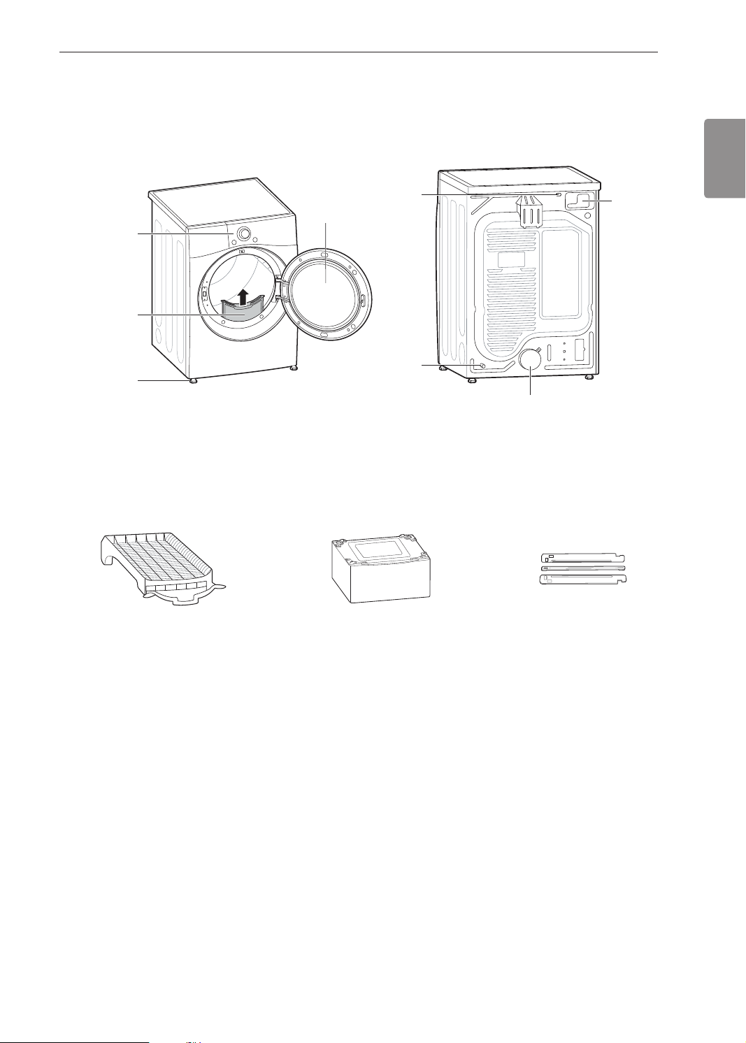
Parts
Control panel
Lint lter
Leveling feet
Accessories
Included Accessories
Reversible
door
Power Cord
(gas models)
Gas connection
(gas models)
Optional Accessories
ENGLISH
Terminal Block
Access Panel
(electric models)
Exhaust Duct Outlet
Drying Rack
Pedestal (sold separately) Stacking kit (sold separately)
(on some models)
NOTE
• For your safety and extended product life, use only authorized components. The manufacturer is not
responsible for product malfunction or accidents caused by the use of unauthorized components or parts.
• The images in this manual may be different from the actual components and accessories that are subject to
change by the manufacturer without prior notice for product improvement purposes.
10 INSTALLATION
INSTALLATION
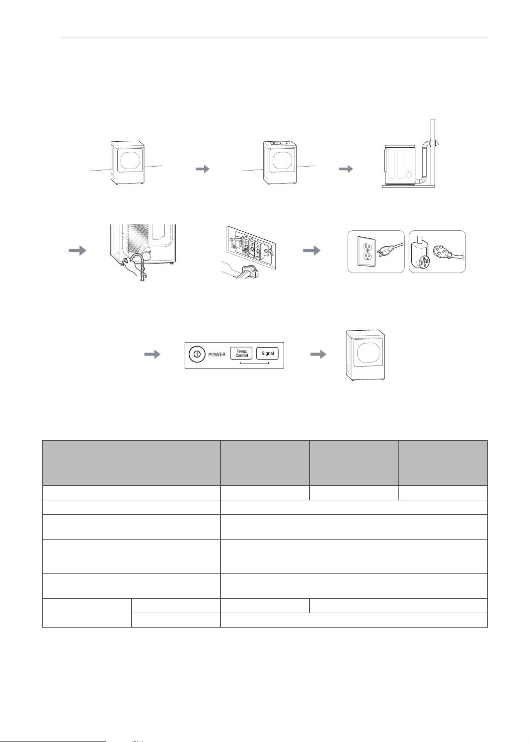
Installation Overview
Please read the following installation instructions rst after purchasing this product or transporting it to another
location.
Check and choose the
proper location
Connect the Gas dryer Connect the Electric dryer Gas dryer Electric dryer
Installation test Test run
Level the dryer Vent the dryer
Plug in the power cord
Product Specications
The appearance and specications listed in this manual may vary due to constant product improvements.
DLE3170*/
Dryer Models
Description Non-steam Dryer Steam Dryer Steam Dryer
Electrical requirements Please refer to the rating label for detailed information.
Gas requirements
Dimensions
Net weight
Drying capacity
Steam Cycle - IEC 7.4 cu.ft. (8 lb/3.6 kg)
Normal Cycle IEC 7.4 cu.ft. (22.5 lb/10.2 kg)
DLG3171*/
DLE3075*/
DLE3180*
NG: 4 - 10.5-inch (10.2 - 26.7 cm) WC
LP: 8 - 13-inch (20.4 - 33.1 cm) WC
27” (W) X 30” (D) X 38.7” (H), 51.4” (D with door open)
68.6 cm (W) X 76.1 cm (D) X 98.3 cm (H), 130.5 cm (D with door
open)
Gas : 124.7 lb (56.6 kg) - 137.5 lb (62.4 kg)
Electric : 122.0 lb (55.3 kg) - 134.1 lb (60.8 kg)
DLEX3370*/
DLGX3371*
DLEX3570*/
DLGX3571*

Installation Location Requirements
11INSTALLATION
WARNING
• Read all installation instructions completely before installing and operating your dryer! It is important that
you review this entire manual before installing and using your dryer. Detailed instructions concerning
electrical connections, gas connections, and exhaust requirements are provided on the following pages.
The installation requires:
• A location that allows for proper exhaust installation. A gas dryer must be exhausted to the outdoors. See
Venting the Dryer.
• A grounded electrical outlet located within 2 ft. (61 cm) of either side of the dryer. See Connecting Electric
Dryers.
• A sturdy oor to support the total dryer weight of 200 lb (90.7 kg). The combined weight of a companion
appliance should also be considered.
• No other fuel-burning appliance can be installed in the same closet as a dryer.
• Additional clearances might be required for wall, door and oor moldings.
• Companion appliance spacing should also be considered.
NOTE
• The oor must be level, with a maximum slope of 1 inch (2.5 cm) under the entire dryer. Clothes may not
tumble properly, and automatic sensor cycles may not operate correctly if the dryer is not level.
• For garage installation, you will need to place the dryer at least 18-inch (46 cm) above the oor. The standard
pedestal is 15-inch (38 cm). You will need 18-inch (46 cm) from the garage oor to the bottom of the dryer.
• Do not operate your dryer at temperatures below 45 °F (7 °C). At lower temperatures, the dryer might not shut
off at the end of an automatic cycle. This can result in longer drying times.
• The dryer must not be installed or stored in an area where it will be exposed to water and/or weather.
• Check code requirements that limit, or do not permit, installation of the dryer in garages, closets, mobile homes
or sleeping quarters. Contact your local building inspector.
ENGLISH
12 INSTALLATION
(25 mm)
(761mm)
(127 mm)
(155 cm
(25 mm)
(25 mm)
(686 mm)
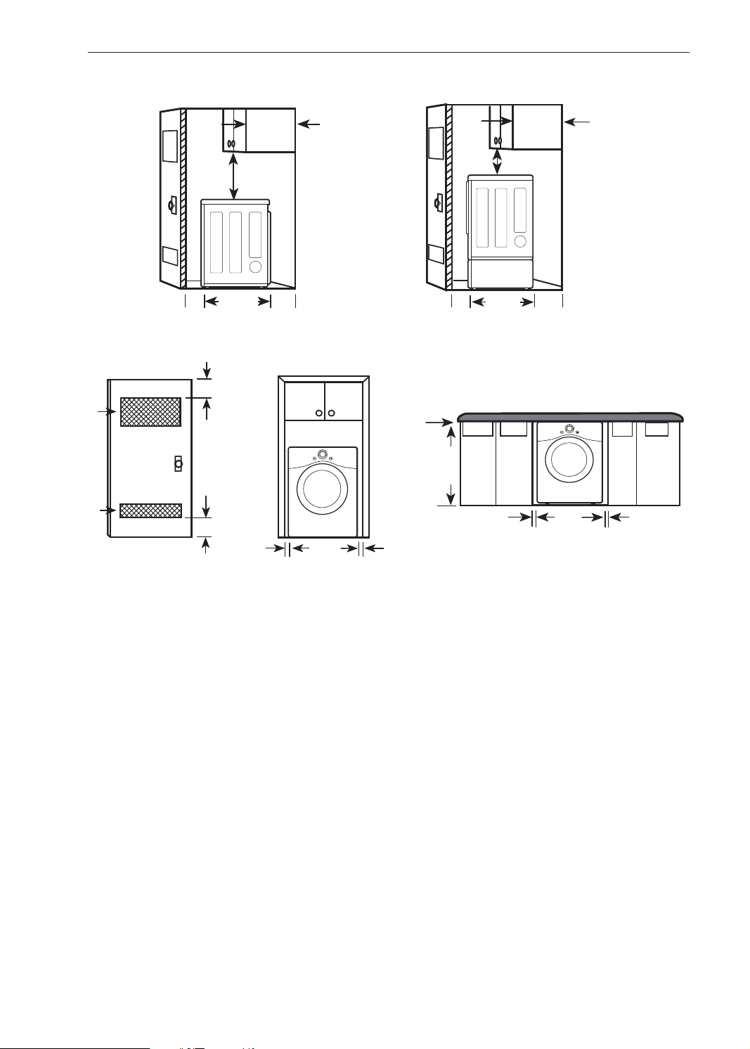
Clearances
18" min.*
(457 mm)
30"
(761mm)
1"
(25 mm)
14" max.*
(356 mm)
5"**
(127 mm)
27"
(686 mm)
1"
(25 mm)
2*
48 in.
2
(310 cm
)
2*
24 in.
2
)
Closet Door
Vent Requirements
1"*
3"
(76 mm)
3"
(76 mm)
*
*
30"
14" max.*
(356 mm)
18" min.*
(457 mm)
5"**
1"
27"
1"
0"
(0 mm)
39"
(991 mm)
1"*
(25 mm)
Installation Spacing for Recessed Area or Closet Installation
The following spacing dimensions are recommended for this dryer. This dryer has been tested for clearances
of 1 inch (2.5 cm) on the sides and rear. Recommended clearances should be considered for the following
reasons:
• Additional clearances should be considered for ease of installation and servicing.
• Additional clearances should be considered on all sides of the dryer to reduce noise transfer. For closet
installation, with a door, minimum ventilation openings in the top and bottom of the door are required. Louvered
doors with equivalent ventilation openings are acceptable.
Closet Ventilation Requirements
Closets with doors must have both an upper and lower vent to prevent heat and moisture buildup in the closet.
One upper vent opening with a minimum opening of 48 sq. in. (310 cm
above the oor. One lower vent opening with a minimum opening of 24 sq. in. (155 cm
2
) must be installed no lower than 6 feet
2
) must be installed no
more than one foot above the oor. Install vent grills in the door or cut down the door at the top and bottom to
form openings. Louvered doors with equivalent ventilation openings are also acceptable.
NOTE
• There should be at least a little space around the dryer (or any other appliance) to eliminate the transfer of
vibration from one appliance to another. If there is enough vibration, it could cause appliances to make noise or
come into contact, causing paint damage and further increasing noise.
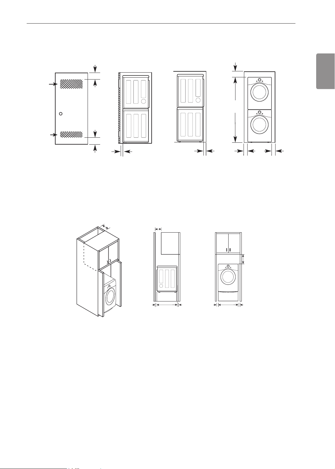
Installation Spacing for Recessed Area or Closet, with Stacked Washer and
(155 cm
(310 cm
(25 mm)
(25 mm)
(686 mm)
7" *
7" *
(229 mm)
Dryer
6"
(152 mm)
77 ½"
(1968 mm)
1"
*
27"
1"
48 in.
24 in.
3"
*
2*
2
)
2*
2
)
(76 mm)
3"
*
(76 mm)
1"*
(25 mm)
5 ½"
**
(140 mm)
* Required spacing
** For side or bottom venting, 2-inch (5.1 cm) of spacing is allowed.
Installation Spacing for Cabinet
For cabinet installation with a door, minimum ventilation openings in the top of the cabinet are required.
* Required spacing
13INSTALLATION
ENGLISH
(178 mm)
(178 mm)
5"*
(127 mm)
30"
(761 mm)
1"*
(25 mm)
1"
(25 mm)
27"
(686 mm)
9" **
1"
(25 mm)
14 INSTALLATION
Leveling the Dryer
WARNING
To reduce the risk of serious injury or death,
follow basic precautions, including the
following:
• Use long-sleeved gloves and safety glasses.
• The appliance is heavy. Two or more people are
required when installing the dryer.
NOTE
• Adjust the leveling feet only as far as necessary
to level the dryer. Extending the leveling feet more
than necessary may cause the dryer to vibrate.
• To ensure that the dryer provides optimal drying
performance, it must be level. To minimize vibration,
noise, and unwanted movement, the oor must be a
perfectly level, solid surface.
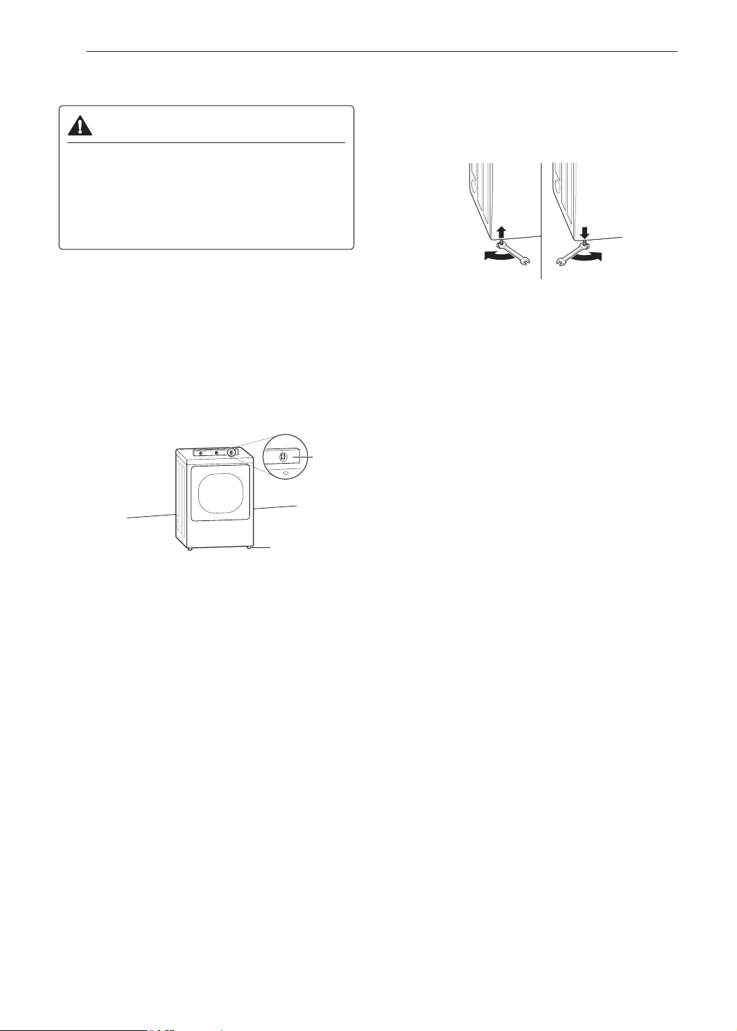
Position the dryer in the nal location. Place a
1
level across the top of the dryer.
Level
Use an adjustable wrench to turn the leveling
2
feet. Unscrew the legs to raise the dryer or
screw the legs to lower it. Raise or lower with
the leveling feet until the dryer is level from side
to side and front to back. Make sure that all four
leveling feet are in rm contact with the oor.
Leveling Feet
• All four leveling feet must rest solidly on the
oor. Gently push on the top corners of the
dryer to make sure that the dryer does not rock
from corner to corner.
NOTE
• If you are installing the dryer on the optional
pedestal, you must use the leveling feet on the
pedestal to level the dryer. The dryer leveling feet
should be fully retracted.
15INSTALLATION
Reversing the Door
Tools Required
• Phillips screwdriver
• Large at blade screwdriver (recommended for
hinge screws if they are tight or your Phillips
screwdriver is worn)
• Small at blade screwdriver (for lifting out parts)
WARNING
To reduce the risk of damage to the dryer,
property damage or personal injury, follow
basic precautions, including the following:
• Support the door with a stool or box that ts
under the door, or have an assistant support the
weight of the door.
• Avoid dropping the door.
• Unplug the dryer or turn off power at the main
circuit breaker before beginning door reversal.
• Always reverse the door BEFORE stacking the
dryer on top of the washer.
While supporting the door, remove the 2 screws
2
on the door hinge. Remove the door.
Turn the door upside down and line up the
3
holes in the hinge with the holes in the cabinet.
Reinstall the door with the screws removed in
step 2.
ENGLISH
Door Reversal Instructions
The instructions here are for changing the door swing
from a right to a left side hinge. If the door has been
reversed, and it is necessary to change it back, use
care when following these instructions. Some of
the illustrations and the left/right references will be
reversed, and you will need to read the instructions
carefully.
WARNING
• Be sure to support the weight of the door before
removing the hinge screws.
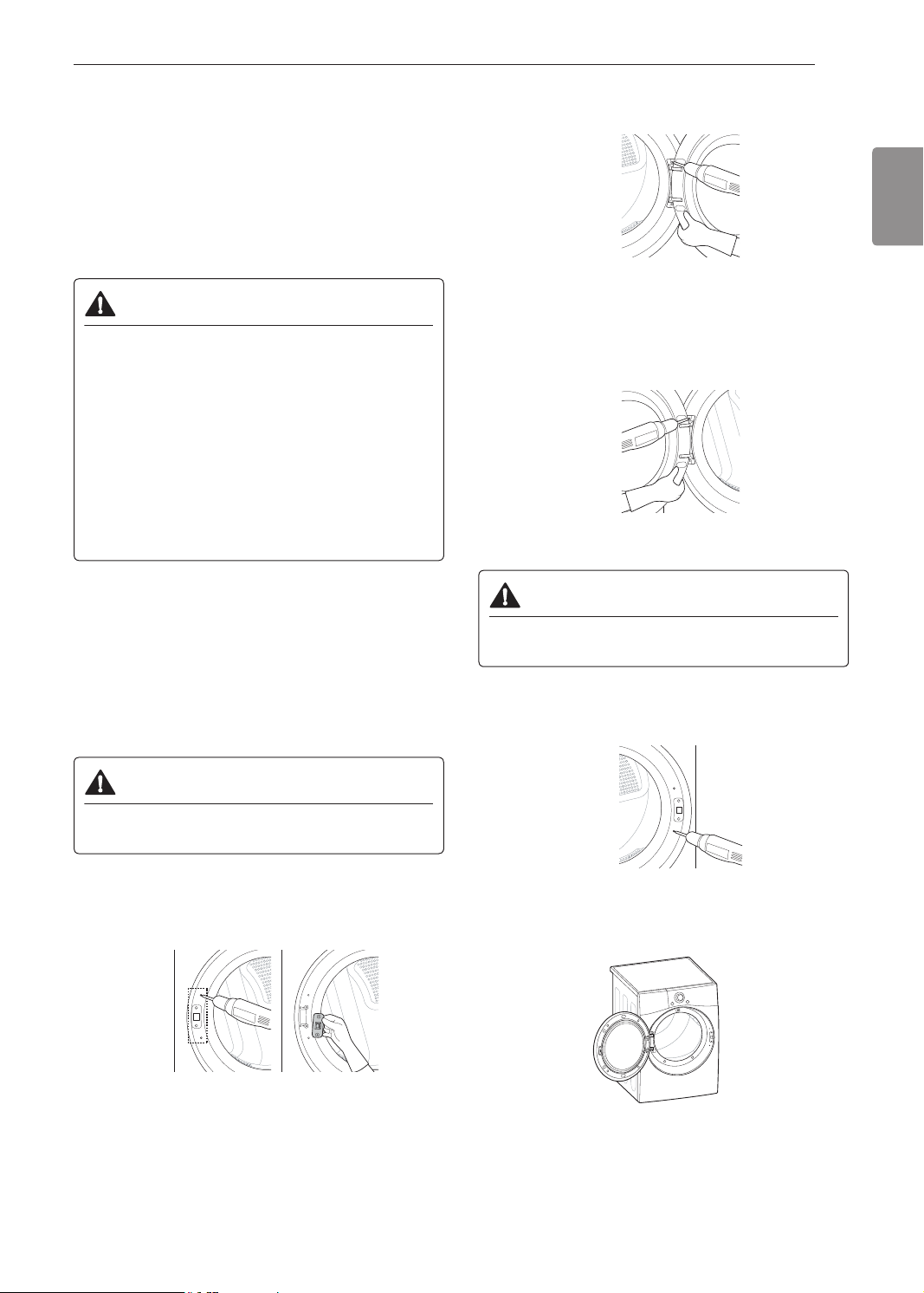
Open the door and remove the two decorative
1
screws, two latch screws, and the latch on the
catch side with a screwdriver. Save these for
step 4.
WARNING
• Be sure to support the weight of the door before
installing the hinge screws.
Install the two decorative screws, the latch,
4
and two latch screws removed in step 1 on the
opposite side from which they were removed.
Check that the door closes properly.
5
16 INSTALLATION
Installing the Side Vent Kit
WARNING
To reduce the risk of serious injury, death or
property damage, follow basic precautions,
including the following:
• Use long-sleeved gloves and safety glasses.
• Use a heavy metal vent.
• Do not use plastic or thin foil ducts.
• Clean old ducts before installing this dryer.
Your new dryer is congured to vent to the rear. It can
also vent to the bottom or side (right-side venting is
not available on gas models).
An adapter kit, part number 383EEL9001B, may be
purchased from your LG retailer. This kit contains
duct components necessary to change the dryer vent
location.
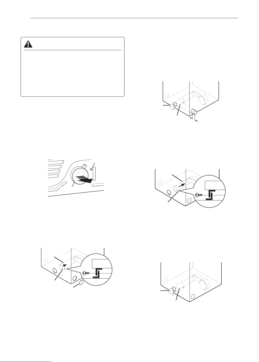
Remove the rear exhaust duct retaining screw.
1
Pull out the exhaust duct.
Retaining Screw
Preassemble a 4-inch (10.2 cm) elbow to the
3
next 4-inch (10.2 cm) duct section, and secure
all joints with duct tape. Be sure that the male
end of the elbow faces AWAY from the dryer.
Insert the elbow/duct assembly through the
side opening and press it onto the adapter duct.
Secure it in place with duct tape. Be sure that
the male end of the duct protrudes 1.5-inch (3.8
cm) to connect the remaining ductwork. Attach
the cover plate to the back of the dryer with the
included screw.
Cover Plate
Elbow
1½" (38 mm)
Option 2: Bottom Venting
Press the adapter duct onto the blower housing
2
and secure it to the base of the dryer as shown.
Rear Exhaust Duct
Option 1: Side Venting
Press the tabs on the knockout and carefully
2
remove the knockout for the desired vent
opening (right-side venting is not available on
gas models). Press the adapter duct onto the
blower housing and secure to the base of the
dryer as shown.
Adapter Duct
Bracket
Knockout
Adapter Duct
Bracket
Insert the 4-inch (10.2 cm) elbow through the
3
rear opening and press it onto the adapter duct.
Be sure that the male end of the elbow faces
down through the hole in the bottom of the
dryer. Secure it in place with duct tape. Attach
the cover plate to the back of the dryer with the
included screw.
Cover Plate
Elbow
17INSTALLATION
Stacking the Dryer
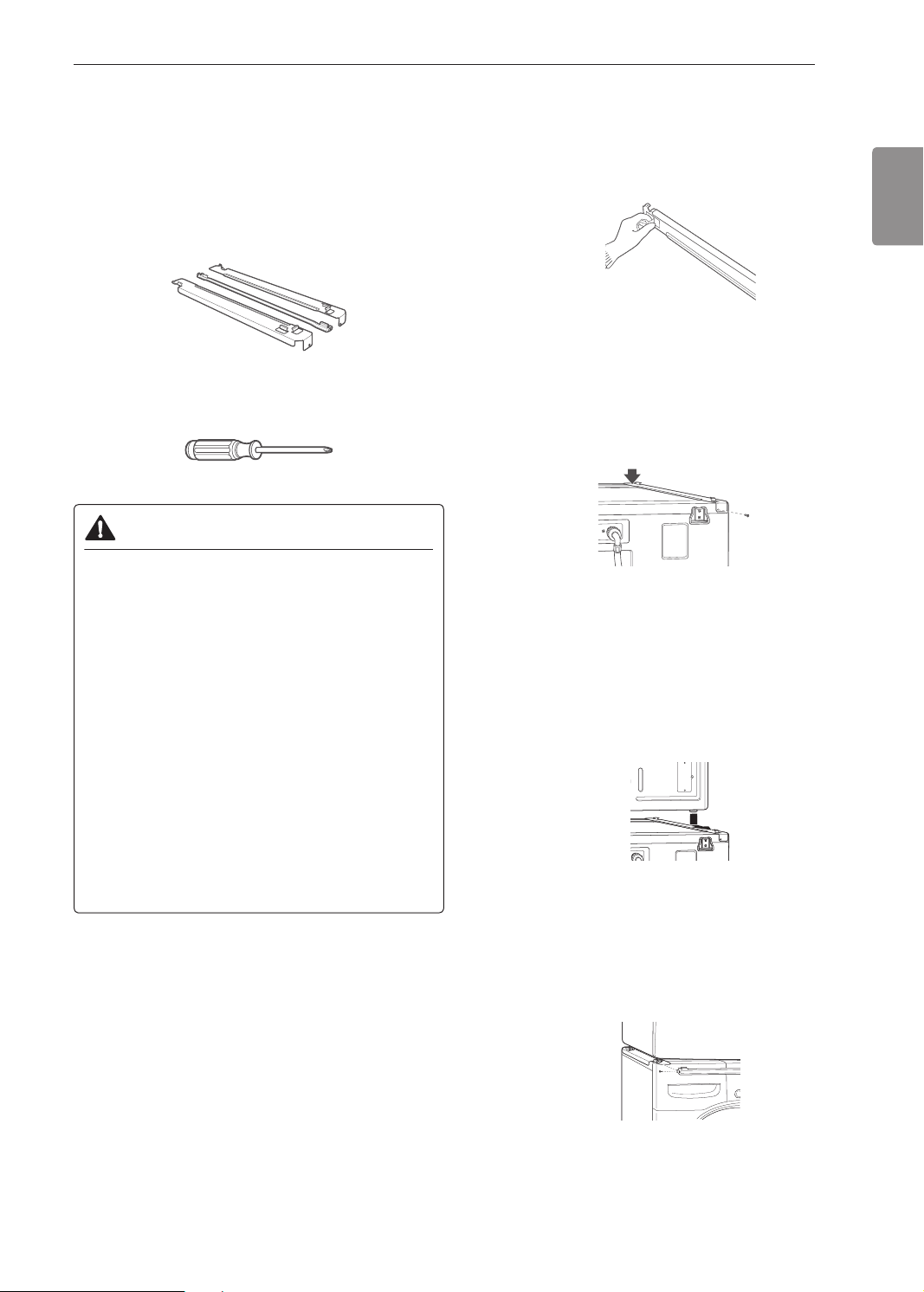
Stacking Kit Installation
This stacking kit includes:
• Two (2) side rails
• One (1) front rail
• Four (4) screws
Tools Needed for Installation:
• Phillips screwdriver
WARNING
To reduce the risk of electrical shock, re,
explosion, property damage, serious injury or
death, follow basic precautions, including the
following:
• The weight of the dryer and the height of
installation make this stacking procedure too
risky for one person. Two or more people are
required when installing the stacking kit.
• Do not use the stacking kit with a gas dryer in
potentially unstable conditions such as a mobile
home.
• Place the washer on a solid, stable, level
oor capable of supporting the weight of both
appliances.
• Do not stack the washer on top of the dryer.
• If appliances are already installed, disconnect
them from all power, water, or gas lines and from
draining or venting connections.
To ensure safe and secure installation, please
observe the following instructions.
Make sure the surface of the washer is clean
1
and dry. Remove paper backing from the tape
on one of the stacking kit side brackets.
Fit the side bracket to the side of the washer top
2
as shown in the above illustration. Firmly press
the adhesive area of the bracket to the washer
surface. Secure the side bracket to the washer
with a screw on the back side of the bracket.
Repeat steps 1 and 2 to attach the other side
bracket.
Place the dryer on top of the washer by
3
tting the dryer feet into the side brackets as
illustrated. Avoid nger injuries; do not allow
ngers to be pinched between the washer and
dryer.
Slowly slide the dryer toward the back of the
washer until the side bracket stoppers catch the
dryer feet.
Insert the front rail between the bottom of the
4
dryer and the top of the washer. Push the front
rail toward the back of the washer until it comes
in contact with the side rail stoppers.
Install the two remaining screws to secure the
front rail to the side rails.
ENGLISH
18 INSTALLATION
a
a
b
Venting the Dryer
WARNING
To reduce the risk of re or explosion, electric
shock, property damage, injury to persons or
death when using this appliance, follow basic
safety precautions, including the following:
• Do not crush or collapse ductwork.
• Do not allow ductwork to rest on or contact sharp
objects.
• If connecting to existing ductwork, make sure it is
suitable and clean before installing the dryer.
• Venting must conform to local building codes.
• Gas dryers MUST exhaust to the outdoors.
• Use only 4-inch (10.2 cm) rigid, semi-rigid or
exible metal ductwork inside the dryer cabinet
and for venting outside.
• To reduce the risk of re, combustion, or
accumulation of combustible gases, DO
NOT exhaust dryer air into an enclosed and
unventilated area, such as an attic, wall, ceiling,
crawl space, chimney, gas vent, or concealed
space of a building.
• To reduce the risk of re, DO NOT exhaust the
dryer with plastic or thin foil ducting.
• The exhaust duct must be 4-inch (10.2 cm) in
diameter with no obstructions. The exhaust duct
should be kept as short as possible. Make sure
to clean any old ducts before installing your new
dryer.
• Rigid, semi-rigid or exible metal ducting is
recommended for use between the dryer and
the wall. All non-rigid metal transition duct must
be UL-listed. Use of other materials for transition
duct could affect drying time.
• DO NOT use sheet metal screws or other
fasteners which extend into the duct that could
catch lint and reduce the efciency of the
exhaust system. Secure all joints with duct tape.
• Do not exceed the recommended duct length
limitations noted in the chart. Failure to follow
these instructions may result in extended drying
times, re or death.
WARNING
• Ductwork is not provided with the dryer. You
should obtain the necessary ductwork locally.
The vent hood should have hinged dampers to
prevent backdraft when the dryer is not in use.
• The total length of exible metal duct must not
exceed 8 ft. (2.4 m).
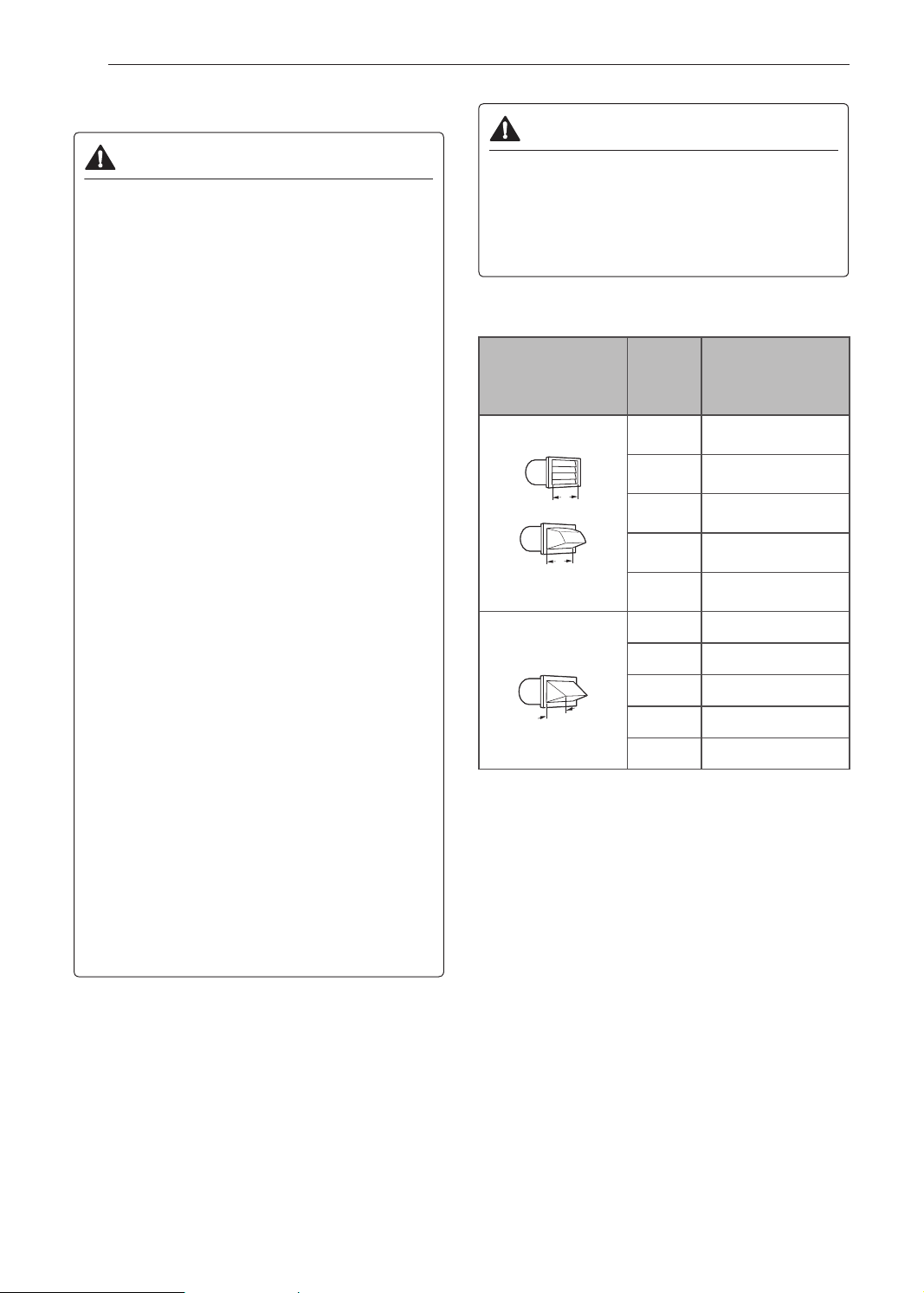
Ductwork
Wall Cap Type
of 90°
Elbows
Number
Recommended
a: 4" (10.2 cm)
Use only for short
run installations
b: 2.5" (6.35 cm)
0 65 ft.(19.8 m)
1 55 ft.(16.8 m)
2 47 ft.(14.3 m)
3 36 ft.(11.0 m)
4 28 ft.(8.5 m)
0 55 ft.(16.8 m)
1 47 ft.(14.3 m)
2 41 ft.(12.5 m)
3 30 ft.(9.1 m)
4 22 ft.(6.7 m)
NOTE
• Deduct 6 ft. (1.8 m) for each additional elbow. Do
not use more than four 90° elbows.
• In Canada, only those foil-type exible ducts, if any,
specically identied for use with the appliance by
the manufacturer should be used. In the United
States, only those foil-type exible ducts, if any,
specically identied for use with the appliance by
the manufacturer and that comply with the Outline
for Clothes Dryer Transition Duct, Subject 2158A,
should be used.
Maximum
length of 4-inch
diameter rigid
metal duct
19INSTALLATION
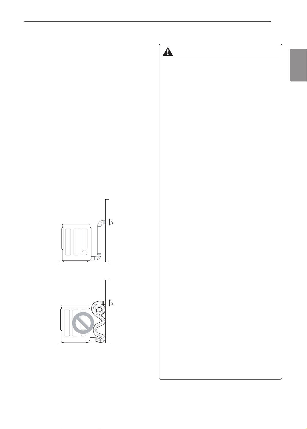
Routing and Connecting Ductwork
NOTE
Follow the guidelines below to maximize drying
performance and reduce lint buildup and
condensation in the ductwork. Ductwork and
ttings are NOT included and must be purchased
separately.
• Use 4-inch (10.2 cm) diameter rigid, semi-rigid or
exible metal ductwork.
• The exhaust duct run should be as short as
possible.
• Use as few elbow joints as possible.
• The male end of each section of exhaust duct must
point away from the dryer.
• Use duct tape on all duct joints.
• Insulate ductwork that runs through unheated areas
in order to reduce condensation and lint buildup on
duct surfaces.
• Incorrect or inadequate exhaust systems are not
covered by the dryer warranty. Dryer failures or
service required because of such exhaust systems
will not be covered by the dryer warranty.
Correct Venting
Connecting Gas Dryers
WARNING
To reduce the risk of re or explosion, electric
shock, property damage, injury to persons,
or death when using this appliance, follow
requirements including the following:
Electrical Requirements for Gas
Models Only
• Do not, under any circumstances, cut or remove
the third (ground) prong from the power cord.
• For personal safety, this dryer must be properly
grounded.
• This dryer must be plugged into a 120-VAC, 60-
Hz. grounded outlet protected by a 15-ampere
fuse or circuit breaker.
• Where a standard 2-prong wall outlet is
encountered, it is your personal responsibility
and obligation to have it replaced with a properly
grounded 3-prong wall outlet.
ELECTRIC SHOCK HAZARD
Failure to follow safety warnings could result
in serious injury
• This dryer is equipped with a three-prong
grounding plug for protection against shock
hazard and should be plugged directly into a
properly grounded three-prong receptacle. Do
not cut or remove the grounding prong from this
plug.
ENGLISH
Incorrect Venting
Gas Supply Requirements
• As shipped from the factory, this dryer is
congured for use with natural gas (NG). It can
be converted for use with propane (LP) gas.
Gas pressure must not exceed 8-inch (20.4 cm)
water column for NG, or 13-inch (33.1 cm) water
column for LP.
• A qualied service or gas company technician
must connect the dryer to the gas service.
• Isolate the dryer from the gas supply system by
closing its individual manual shutoff valve during
any pressure testing of the gas supply.
• DO NOT attempt any disassembly of the dryer;
disassembly requires the attention and tools of
an authorized and qualied service technician or
company.
• Securely tighten all gas connections.
• Connect the dryer to the type of gas shown on
the nameplate.
20 INSTALLATION
WARNING
Gas Supply Requirements (continued)
• Supply line requirements: Your laundry room
must have a rigid gas supply line to your dryer.
In the United States, an individual manual shutoff
valve MUST be installed within at least 6 ft. (1.8
m) of the dryer, in accordance with the National
Fuel Gas Code ANSI Z223.1 or Canadian gas
installation code CSA B149.1. A 1/8-inch NPT
pipe plug must be installed.
• If using a rigid pipe, the rigid pipe should be
0.5-inch IPS. If acceptable under local codes and
ordinances and when acceptable to your gas
supplier, 3/8-inch approved tubing may be used
where lengths are less than 20 ft. (6.1 m). Larger
tubing should be used for lengths in excess of 20
ft. (6.1 m).
• To prevent contamination of the gas valve,
purge the gas supply of air and sediment before
connecting the gas supply to the dryer. Before
tightening the connection between the gas
supply and the dryer, purge remaining air until
the odor of gas is detected.
• DO NOT use an open ame to inspect for gas
leaks. Use a noncorrosive leak detection uid.
• Use only a new AGA- or CSA-certied
gas supply line with exible stainless steel
connectors.
• Use Teon tape or a pipe-joint compound that is
insoluble in propane (LP) gas on all pipe threads.
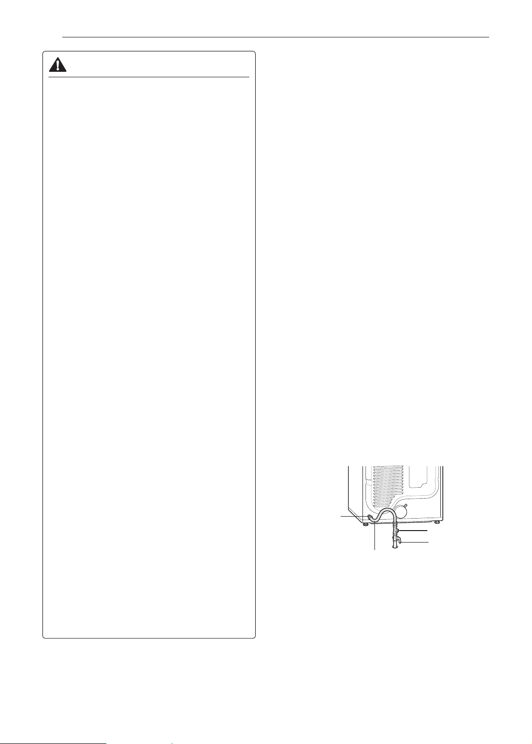
Connecting the Gas Supply
• Installation and service must be performed by
a qualied installer, service agency, or the gas
supplier.
• Use only a new stainless steel exible connector
and a new AGA-certied connector.
• A gas shutoff valve must be installed within 6 ft.
(1.8 m) of the dryer.
• The dryer is congured for natural gas when
shipped from the factory. Make sure that the
dryer is equipped with the correct burner nozzle
for the type of gas being used (natural gas or
propane gas).
• If necessary, the correct nozzle (for the LP
nozzle kit, order part number 383EEL3002D)
should be installed by a qualied technician and
the change should be noted on the dryer.
• All connections must be in accordance with
local codes and regulations. Gas dryers MUST
exhaust to the outdoors.
NOTE
• In the Commonwealth of Massachusetts: This
product must be installed by a licensed plumber
or gas tter. When using ball-type gas shut off
valves, they shall be T-handle-type. A exible gas
connector, when used, must not exceed 3 feet.
This dryer is congured from the factory for natural
gas (NG). If the dryer is to be used with propane
(LP) gas, it must be converted by a qualied service
technician.
Make sure that the gas supply to the laundry
1
room is turned OFF and the dryer is unplugged.
Conrm that the type of gas available in your
laundry room is appropriate for the dryer.
Remove the shipping cap from the gas tting at
2
the back of the dryer. Be careful not to damage
the threads of the gas connector when removing
the shipping cap.
Connect the dryer to your laundry room’s gas
3
supply using a new exible stainless steel
connector with a 3/8-inch NPT tting.
NOTE
• DO NOT use old connectors.
Securely tighten all connections between the
4
dryer and your laundry room’s gas supply.
Turn on your laundry room’s gas supply.
5
Check all pipe connections (both internal and
6
external) for gas leaks with a noncorrosive leak-
detection uid.
Proceed to Venting the Dryer.
7
3/8" NPT gas
Connection
1/8" NPT Pipe Plug
AGA/CSA-Certied
Stainless Steel Flexible
Connector
Gas Supply Shutoff
Valve
High-Altitude Installations
The BTU rating of this dryer is AGA-certied for
elevations below 10,000 feet.
If your gas dryer is being installed at an elevation
above 10,000 feet, it must be derated by a qualied
technician or gas supplier.

Connecting Electric Dryers
WARNING
To reduce the risk of re or explosion, electric
shock, property damage, injury to persons,
or death when using this appliance, follow
requirements including the following:
Electrical Requirements for
Electric Models Only
• The wiring and grounding must conform to
the latest edition of the National Electrical
Code, ANSI/NFPA 70 and all applicable local
regulations. Please contact a qualied electrician
to check your home’s wiring and fuses to ensure
that your home has adequate electrical power to
operate the dryer.
• This dryer must be connected to a grounded
metal, permanent wiring system, or an
equipment-grounding conductor must be run
with the circuit conductors and connected to the
equipment-grounding terminal or lead on the
dryer.
• The dryer has its own terminal block that must
be connected to a separate 240 VAC, 60-Hertz,
single-phase circuit, fused at 30 amperes (the
circuit must be fused on both sides of the line).
ELECTRICAL SERVICE FOR THE DRYER
SHOULD BE OF THE MAXIMUM RATE
VOLTAGE LISTED ON THE NAMEPLATE. DO
NOT CONNECT THE DRYER TO 110-, 115-, OR
120-VOLT CIRCUIT.
• If the branch circuit to dryer is 15 ft. (4.5
m) or less in length, use UL (Underwriters
Laboratories) listed No.-10 AWG wire (copper
wire only), or as required by local codes. If over
15 ft. (4.5 m), use UL-listed No.-8 AWG wire
(copper wire only), or as required by local codes.
Allow sufcient slack in wiring so the dryer
can be moved from its normal location when
necessary.
• The power cord (pigtail) connection between the
wall receptacle and the dryer terminal block IS
NOT supplied with the dryer. Type of pigtail and
gauge of wire must conform to local codes and
with instructions on the following pages.
WARNING
• A 4-wire connection is required for all mobile and
manufactured home installations, as well as all
new construction after January 1, 1996. A 4-wire
connection must be used where local codes do
not permit grounding through the neutral wire.
• Do not modify the plug and internal wire provided
with the dryer.
• The dryer should be connected to a 4-hole outlet.
• If the plug does not t the outlet, a proper outlet
will need to be installed by a qualied electrician.
• Connect the power cord to the terminal block.
Each colored wire should be connected to
the same color screw. Wire color indicated on
manual is connected to the same color screw in
the block.
• Grounding through the neutral conductor is
prohibited for: (1) new branch-circuit installations,
(2) mobile homes, (3) recreational vehicles, and
(4) areas where local codes prohibit grounding
through the neutral conductor.
• This dryer is supplied with the neutral wire
grounded. This white ground wire MUST BE
MOVED to the neutral terminal when a 4-wire
cord is to be used, or where grounding through
the neutral conductor is prohibited.
NOTE
• For electrical requirements for mobile or
manufactured homes, see Special Electrical
requirements.
21INSTALLATION
ENGLISH

22 INSTALLATION
Special Electrical Requirements
(For Mobile or Manufactured Homes)
• Any installation in a manufactured or mobile
home must comply with the Manufactured Home
Construction and Safety Standards Title 24 CFR,
Part 3280 or Standard CAN/ CSA Z240 MH and
local codes and ordinances. If you are uncertain
whether your proposed installation will comply with
these standards, please contact a service and
installation professional for assistance.
• A 4-wire connection is required for all mobile and
manufactured home installations, as well as all new
construction after January 1, 1996.
• A gas dryer must be permanently attached to the
oor.
• The electrical connection for an electric dryer must
be a 4-wire connection. More detailed information
concerning the electrical connection is provided in
the section Connecting Electric Dryers.
• To reduce the risk of combustion and re, the dryer
must be vented to the outside.
• DO NOT vent the dryer under a manufactured home
or mobile home.
• Electric dryers may be vented to the outside using
the back, left, right, or bottom panel.
• Gas dryers may be vented to the outside using the
back, left, or bottom panel. Gas dryers may not
be vented to the outside using the right side panel
because of the burner housing.
• The dryer exhaust duct must be afxed securely to
the manufactured or mobile home structure, and the
exhaust duct must be made of a material that will
resist re and combustion. It is recommended that
you use a rigid, semi-rigid or exible metal duct.
• DO NOT connect the dryer exhaust duct to any
other duct, vent, chimney, or other exhaust duct.
• Make sure the dryer has adequate access to
outside fresh air to ensure proper operation. The
opening for outside fresh air must be at least 25 sq.
in (163 cm²).
• It is important that the clearance of the duct from
any combustible construction be at least 2-inch (5
cm), and when venting the dryer to the outdoors,
the dryer should be installed with a clearance of at
least 1 inch (2.5 cm) at the sides and back of the
dryer.
• Please be aware that venting materials are not
supplied with the dryer. You must obtain the venting
materials necessary for proper installation.
Final Installation Check
Once you have completed the installation of the dryer
and it is in its nal location, conrm proper operation
with the following tests and Installation Test (Duct
Check).
Testing Dryer Heating
GAS MODELS
Close the dryer door and press the Power button
to turn the dryer on. Press the Time Dry and Start/
Pause buttons to start the test. When the dryer starts,
the igniter should ignite the main burner.
NOTE
• If all air is not purged from the gas line, the gas
igniter may turn off before the main burner ignites. If
this happens, the igniter will reattempt gas ignition
after approximately two minutes.
ELECTRIC MODELS
Close the dryer door and press the Power button
to turn the dryer on. Press the Time Dry and Start/
Pause buttons to start the test. The exhaust air
should be warm after the dryer has been operating
for 3 minutes.
Checking Airow
Effective dryer operation requires proper airow.
The adequacy of the airow can be measured by
evaluating the static pressure. Static pressure in the
exhaust duct can be measured with a manometer,
placed on the exhaust duct approximately 2 ft. (60.9
cm) from the dryer. Static pressure in the exhaust
duct should not exceed 0.6-inch (1.5 cm). The dryer
should be checked while the dryer is running with no
load.
Checking Levelness
Once the dryer is in its nal location, recheck the
dryer to be sure it is level. Make sure it is level front
to back and side to side, and that all four leveling feet
are in rm contact with the oor.
23INSTALLATION
Installation Test (Duct Check)
Once you have completed the installation of the
dryer, use this test to make sure the condition of the
exhaust system is adequate for proper operation of
the dryer. This test should be performed to alert you
to any serious problems in the exhaust system of
your home.
• Your dryer features Flow Sense™, an innovative
sensing system that automatically detects
blockages and restrictions in dryer ductwork.
Keeping ductwork clean of lint buildup and free of
restrictions allows clothes to dry faster and reduces
energy use.
NOTE
• The dryer should be cool before starting this test.
If the dryer was warmed up during installation, run
the AIR DRY cycle for a few minutes to reduce the
interior temperature.
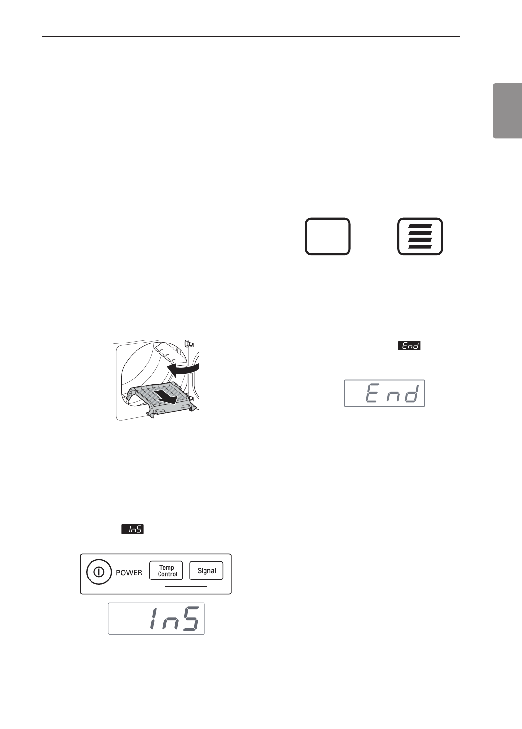
Activating the Installation Test
Remove the drying rack and literature, and
1
then close the door.
Do not load anything in the drum for this test, as
it may affect the accuracy of the results.
Press the Start/Pause button.
3
The dryer will start the test, which will last about
a few minutes. The heat will be turned on and
the temperatures in the drum will be measured.
Check the display for results.
4
During the test cycle, monitor the Flow Sense™
display on the control panel. If no bars are
displayed when the cycle ends, the exhaust
system is adequate. If the exhaust system is
severely restricted, the display will show four
bars. Have the system checked immediately, as
performance will be poor. Other problems may
also be shown with error codes. Refer to the the
Error Code table for details and solutions.
NO BARS: OK FOUR BARS:
End of cycle.
5
At the end of the test cycle,
The test cycle will end and the dryer will shut off
automatically after a short delay.
RESTRICTED
will display.
ENGLISH
Press and hold the Signal and Temp. Control
2
buttons and then press the Power button.
(On models with a glass touch control panel,
press the Power button then IMMEDIATELY
press and hold the Temp. Control and Signal
buttons.)
This button sequence activates the installation
test. The code
is successful.
will display if the activation

24 INSTALLATION
Check the Duct Condition
If the Flow Sense™ LED is turned on, check the
exhaust system for restrictions and damage. Repair
or replace the exhaust system as needed.
NOTE
• When the dryer is rst installed, this test should be
performed to alert you to any existing problems with
the exhaust duct in your home. However, since the
test performed during normal operation provides
more accurate information on the condition of the
exhaust duct than the installation test, the number
of bars displayed during the two tests may not be
the same.
• Do not interrupt the test cycle, as this could result in
inaccurate results.
• Even if no bars are displayed during the test cycle,
some restrictions may still be present in the exhaust
system. Refer to the Venting the Dryer section
of this manual for complete exhaust system and
venting requirements.
• Your dryer features Flow Sense™, an innovative
sensing system that automatically detects
blockages and restrictions in the dryer ductwork.
Keeping ductwork clean of lint buildup and free of
restrictions allows clothes to dry faster and reduces
energy use.
Error code
Check the error code before you call for service.
Error
Code
tE1 or
tE2
HS
PS,
PF, or
nP
Possible
Causes
Temperature
sensor failure.
Humidity sensor
failure.
Electric dryer
power cord is
not connected
correctly, or
house power
supply is
incorrect.
House fuse is
blown, circuit
breaker has
tripped, or
power outage
has occurred.
Solutions
Turn off the dryer and call
for service.
Turn off the dryer and call
for service.
Check the power supply
or the connection of
the power cord to the
terminal block. Refer to
the Connecting Electric
Dryers section of this
manual for complete
instructions.
Reset circuit breaker
or replace fuse. Do
not increase the fuse
capacity.
If the problem is a
circuit overload, have it
corrected by a qualied
electrician.
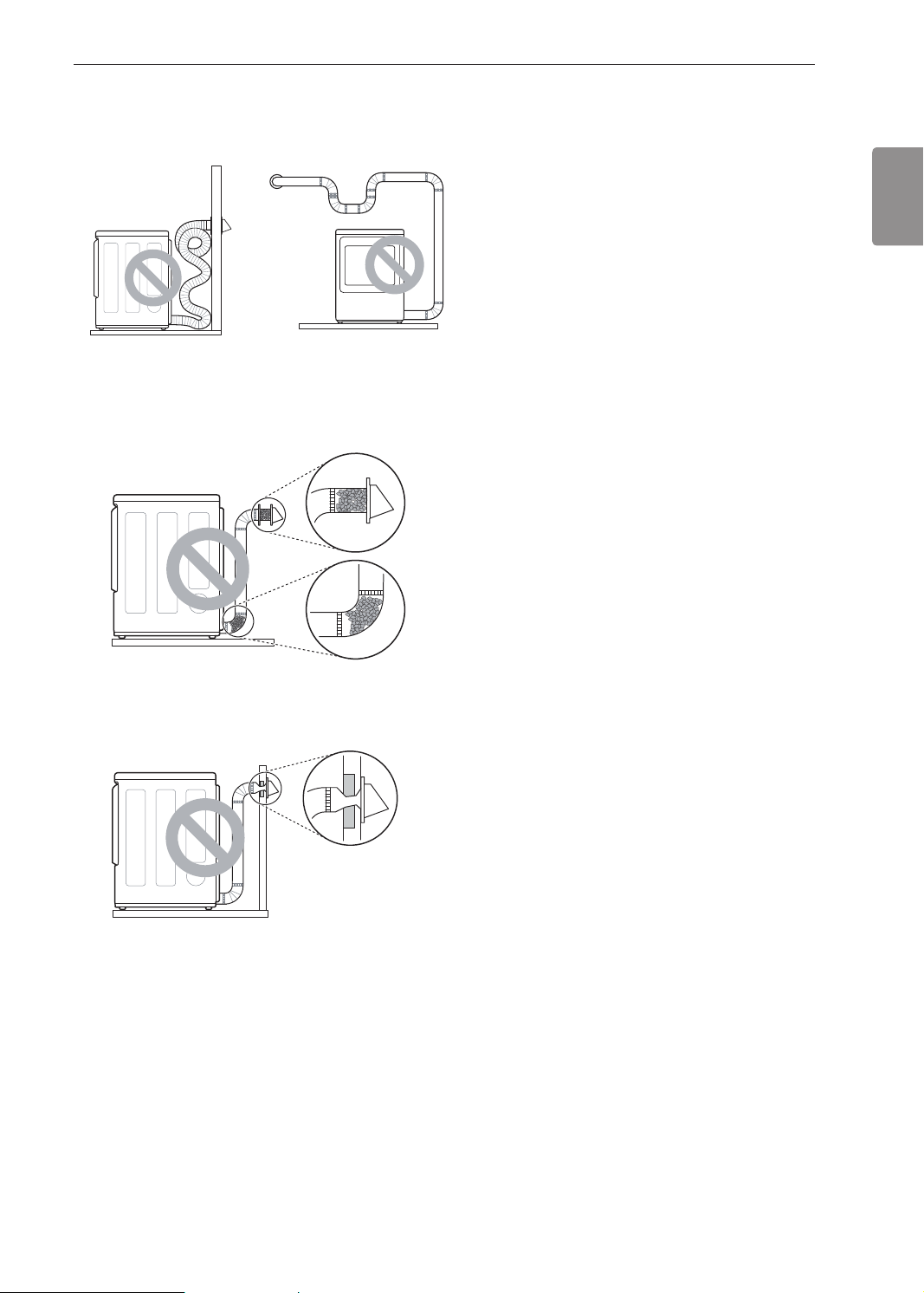
Restricted or Blocked Airow
Avoid long runs or runs with multiple elbows or
bends.
25INSTALLATION
ENGLISH
Excess or crushed
transition duct
Too many elbows or
exhaust too long
Check for blockages and lint buildup.
Lint buildup or blockage
Make sure the ductwork is not crushed or restricted.
Crushed or damaged
exhaust
26 OPERATION
OPERATION
WARNING
• To reduce the risk of re, electric shock, or injury to persons, read the SAFETY INSTRUCTIONS before
operating this appliance.
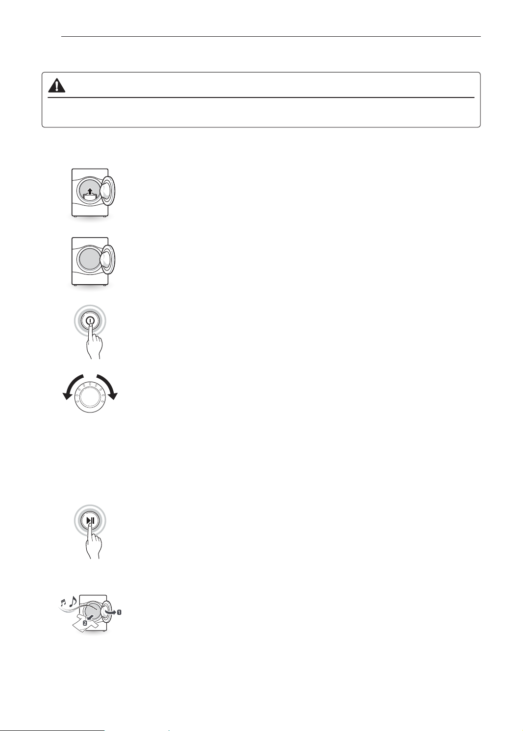
Using the Dryer
1
2
3
4
Clean the Lint Filter
If the lint lter has not already been cleaned, lift out the lter and remove the
lint from the last load. This will help ensure the fastest and most efcient drying
performance. Make sure to reinstall the lter, pressing down until it clicks rmly
into place.
Load the Dryer
Load the dryer with the wet laundry from the washer. If the load is extra large,
you may need to divide it into smaller loads for proper performance and fabric
care.
Turn on the Dryer
Press the Power button to turn ON the dryer. The cycle LEDs will illuminate and
a chime will sound.
Select a Cycle
Turn the cycle selector knob either direction until the LED for the desired cycle
is on. The preset temperature, dry level, and option settings for that cycle will be
shown. Default settings for the selected cycle can now be changed if desired.
Refer to the Cycle Setting and Options page for details.
NOTE
• Not all options or modiers are available on all cycles. Refer to the Cycle
Guide page for default settings and available options. A different chime will
sound and the LED will not come on if the selection is not available.
5
6
Begin Cycle
Press the Start/Pause button to begin the cycle. The cycle can be paused at
any time either by opening the door or by pressing the Start/Pause button. If
the cycle is not restarted within 4 minutes of being paused, the dryer will shut
off and the settings will be lost.
End of Cycle
When the cycle is nished, the chime will sound. Immediately remove your
clothing from the dryer to reduce wrinkling. If Wrinkle Care is selected, the dryer
will tumble briey every few minutes to help prevent wrinkles from setting in the
clothes.
27OPERATION
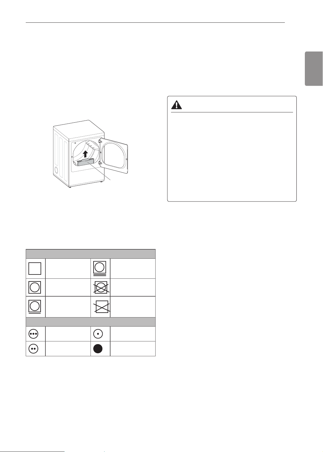
Check the Lint Filter Before Every Load
Always make sure the lint lter is clean before
starting a new load; a clogged lint lter will increase
drying time. To clean, pull the lint lter straight up and
roll any lint off the lter with your ngers. Push the lint
lter rmly back into place. See Regular Cleaning
for more information.
Always ensure the lint lter is properly installed
before running the dryer. Running the dryer with a
loose or missing lint lter will damage the dryer and
articles in the dryer.
Lint Filter
Sorting Laundry
Fabric Care Labels
Many articles of clothing include a fabric care label.
Using the chart below, adjust the cycle and option
selections to care for your clothing according to the
manufacturer’s recommendations.
Tumble dry
Dry Gentle/delicate
Grouping Similar Items
For best results, sort clothes into loads that can be
dried with the same drying cycle.
Different fabrics have different care requirements,
and some fabrics will dry more quickly than others.
Loading the Dryer
WARNING
To reduce the risk of re, explosion, electric
shock, injury to persons, and death when
using this appliance, follow basic precautions,
including the following:
• Check all pockets to make sure that they are
empty. Items such as clips, pens, coins, and
keys can damage both your dryer and your
clothes. Flammable objects such as lighters or
matches could ignite, causing a re.
• Never dry clothes that have been exposed to
oil, gasoline, or other ammable substances.
Washing clothes will not completely remove oil
residues.
NOTE
Loading Tips
• Combine large and small items in the same load.
• Damp clothes will expand as they dry. Do not
overload the dryer; clothes require room to tumble
and dry properly.
• Close zippers, hooks, and drawstrings to prevent
these items from snagging or tangling on other
clothes.
ENGLISH
Normal
Permanent
Press/ wrinkle
resistant
Heat setting
High Low
Medium No heat/air
Do not tumble
dry
Do not dry (used
with do not wash)
28 OPERATION
7
32
5
6
41
78
32
5
6
41
78
32
5
6
41
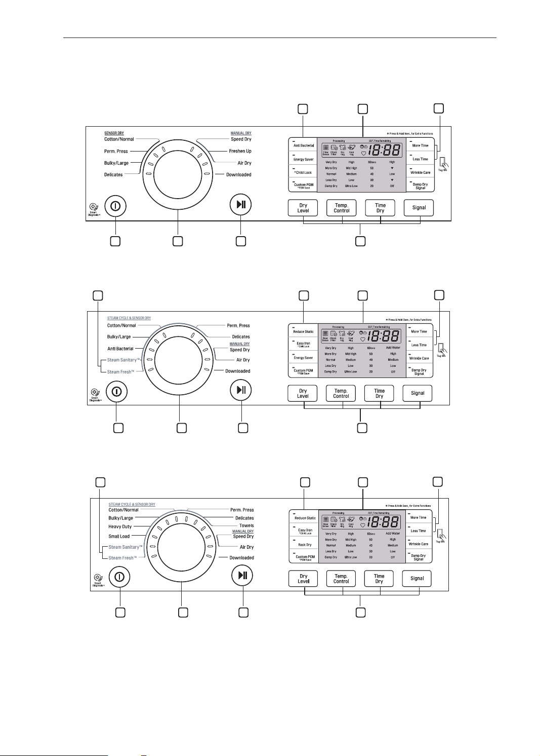
Control Panel
Non-Steam Models (DLE3170*, DLG3171*, DLE3075*, DLE3180*)
Steam Models (DLEX3370*, DLGX3371*)
Steam Models (DLEX3570*,DLGX3571*)
NOTE
• Model numbers can be found on the cabinet inside the door.

29OPERATION
3
4
1
Power Button
Press the button to turn the dryer ON. Press again to
turn the dryer OFF.
NOTE
• Pressing the Power button during a cycle will
cancel that cycle and any load settings will be lost.
2
Cycle Selector Knob
Turn this knob to select the desired cycle. Once
the desired cycle has been selected, the standard
presets will be shown in the display. On Manual Dry
cycles, these settings can be adjusted using the cycle
setting buttons anytime before starting the cycle.
Start/Pause Button
Press this button to start the selected cycle. If the
dryer is running, use this button to pause the cycle
without losing the current settings.
NOTE
• If you do not press the Start/Pause button to
resume a cycle within 4 minutes, the dryer turns off
automatically and all cycle settings are lost.
6
Time and Status Display
The display shows the settings, estimated time
remaining, options, and status messages for the
dryer.
7
Cycle Option Buttons
Press each of these buttons to select additional
cycle options. And press and hold any button marked
with an asterisk for 3 seconds to activate a special
function.
8
Steam Functions
LG’s steam technology allows you to inject fabrics
with a swirling jet of steam to refresh clothes, reduce
static, and make ironing easier. Simply select the
Steam Fresh™ cycle or you can add a Steam option
to selected cycles.
ENGLISH
Cycle Modier Buttons
Use these buttons to select the desired cycle settings
for the selected cycle. The current settings are shown
in the display. Press the button for that option to view
and select other settings.
5
More Time/Less Time Buttons
Use these buttons with the Time Dry and other
Manual Dry cycles to adjust the drying time. Press
the More Time button to increase the selected
manual cycle time by 1 minute; press the Less Time
button to decrease the cycle time by 1 minute.
30 OPERATION
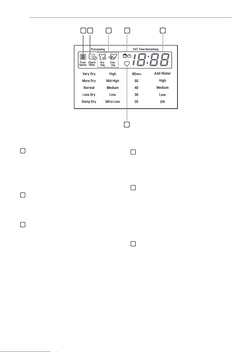
9 10 11 12 13
14
11
Flow Sense™ Duct Blockage Sensing System
9
Indicator
The Flow Sense™ duct blockage sensing system
detects and alerts you to blockages in the ductwork
that reduce exhaust ow from the dryer. Maintaining
a clean exhaust system improves operating efciency
and helps minimize service calls, saving you money.
10
Check Filter Reminder
The display will show Check lter when the dryer is
turned on as a reminder to check the lter. It turns off
when the Start/Pause button is pressed.
Cycle Completion Indicator with Check Filter
Reminder
This portion of the display shows which stage of
the drying cycle is currently underway (Check Filter,
Drying, Cooling).
12
Child Lock Indicator
When Child Lock is set, the Child Lock indicator
appears and all buttons are disabled except the
Power button. This prevents children from changing
settings while the dryer is operating.
13
Estimated Time Remaining
This display shows the estimated time remaining for
Sensor Dry cycles or the actual time remaining for
Time Dry or Manual Dry cycles.
NOTE
• The cycle time on Sensor Dry cycles may uctuate
as the dryer recalculates drying time for optimal
results.
14
Custom PGM
If you have a special combination of settings that
you use frequently, you can save these settings as a
Custom Program.
 Loading...