

Page 1

INSTALLATION MANUAL
AIR
CONDITIONER
ENGLISH
FRANÇAIS
ESPAÑOL
Please read this installation manual completely before installing the product.
Installation work must be performed in accordance with the national wiring
standards by authorized personnel only.
Please retain this installation manual for future reference after reading it thoroughly.
CEILING CONCEALED DUCT
Original instruction
www.lghvac.com
MFL68821907
Rev.04_012220
Copyright © 2018 - 2020 LG Electronics Inc. All Rights Reserved.
www.lg.com
Page 2
IMPORTANT!
Please read this instruction sheet completely before installing the product.
This air conditioning system meets strict safety and operating standards. As the installer or service
person, it is an important part of your job to install or service the system so it operates safely and
efficiently.
!
WARNING
• The information contained in the manual is intended for use by a qualified service technician
familiar with safety procedures and equipped with the proper tools and test instruments.
• Failure to carefully read and follow all instructions in this manual can result in equipment
malfunction, property damage, personal injury and/or death.
Caution: Improper installation, adjustment, alteration, service or maintenance can void the warranty.The
Safety Precautions
Note to installing dealer: The Owners Instructions and Warranty are to be given to the owner or
prominently displayed near the indoor Furnace/Air Handler Unit.
weight of the condensing unit requires caution and proper handling procedures when lifting or
moving to avoid personal injury. Use care to avoid contact with sharp or pointed edges.
• Always wear safety eye wear and work gloves when installing equipment.
• Never assume electrical power is disconnected. Check with meter and equipment.
• Keep hands out of fan areas when power is connected to equipment.
• R-410A causes frostbite burns.
• R-410A is toxic when burned.
!
WARNING
When wiring:
Electrical shock can cause severe personal injury or death. Only a qualified, experienced electrician
should attempt to wire this system.
• Do not supply power to the unit until all wiring and tubing are completed or reconnected and checked.
• Highly dangerous electrical voltages are used in this system. Carefully refer to the wiring diagram and these
instructions when wiring. Improper connections and inadequate grounding can cause accidental injury or death.
• Ground the unit following local electrical codes.
• Connect all wiring tightly. Loose wiring may cause overheating at connection points and a possible fire hazard.
When transporting:
Be careful when picking up and moving the indoor and outdoor units. Get a partner to help, and bend your knees
when lifting to reduce strain on your back. Sharp edges or thin aluminum fins on the air conditioner can cut your
finger.
When installing...
... in a wall: Make sure the wall is strong enough to hold the unit's weight. It may be necessary to construct a
... in a room: Properly insulate any tubing run inside a room to prevent "sweating" that can cause dripping and
... in moist or uneven locatinons: Use a raised concrete pad or concrete blocks provide a solid, level foundation
... in an area with high winds: Securely anchor the outdoor unit down with bolts and a metal frame. Provide a
... in a snowy area(for Heat Pump Model): Install the outdoor unit on a raised platform that is higher than drifting
When connecting refrigerant tubing:
• Keep all tubing runs as short as possible.
• Use the flare method for connecting tubing.
• Check carefully for leaks before starting the test run.
When servicing:
• Turn the power OFF at the main power box(mains) before opening the unit to check or repair electrical parts and
wiring.
• Keep your fingers and clothing away from any moving parts.
• Clean up the site after you finish, remembering to check that no metal scraps or bits of wiring have been left
inside the unit being serviced.
strong wood or metal frame to provide added support.
water damage to wall and floors.
for the outdoor unit. This prevents water damage and abnormal vibration.
suitable air baffle.
snow. Provide snow vents.
2 Indoor Unit
Page 3

TABLE OF CONTENTS
4 FEATURES
5 SAFETY INSTRUCTIONS
8 INSTALLATION
8 Selection of the best location
9 Ceiling dimension and hanging bolt location
10 Indoor Unit Installation
10 Wiring Connection
14 Flaring work
14 Checking the Drainage
15 Indoor Unit Drain Piping
17 DIP Switch Setting
18 Group Control Setting
22 Airborne Noise Emission
22 Limiting concentration
Table of contents
ENGLISH
23 HOW TO SET E.S.P?
Installation Manual 3
Page 4
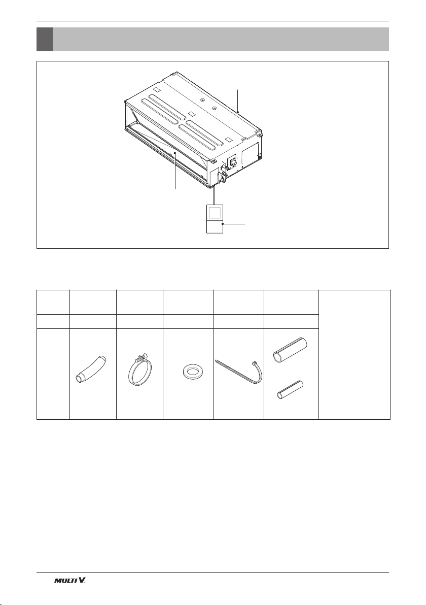
Features
Features
Installation Tool
Name Drain hose Clamp metal
Quantity
1 EA 2 EA 8 EA 4 EA 1 SET
Air outlet vents
Washer for
hanging bracket
Air inlet vents
Remote Controller
(Accessory)
Clamp
(Tie Wrap)
Insulation for
fitting
(Other)
• Owner's manual
Installation manual
•
Shape
4 Indoor Unit
for gas pipe
for liquid pipe
Page 5
Safety Instructions
Safety Instructions
The following safety guidelines are intended to prevent unforeseen risks or damage from
unsafe or incorrect operation of the appliance.
The guidelines are separated into ‘WARNING’ and ‘CAUTION’ as described below.
This symbol is displayed to indicate matters and operations that can cause risk.
!
Read the part with this symbol carefully and follow the instructions in order to avoid risk.
!
WARNING
This indicates that the failure to follow the instructions can cause serious injury or death.
!
CAUTION
This indicates that the failure to follow the instructions can cause the minor injury or
damage to the product.
!
WARNING
ENGLISH
Installation
• Do not use a defective or underrated circuit
breaker. Use this appliance on a dedicated
circuit.
- There is risk of fire or electric shock.
• For electrical work, contact the dealer, seller, a
qualified electrician, or an Authorized Service
Center.
- Do not disassemble or repair the product.
There is risk of fire or electric shock.
• Always ground the product.
-There is risk of fire or electric shock.
• Install the panel and the cover of control box
securely.
- There is risk of fire or electric shock.
• Always install a dedicated circuit and breaker.
- Improper wiring or installation may cause fire
or electric shock.
• Use the correctly rated breaker or fuse.
- There is risk of fire or electric shock.
• Do not modify or extend the power cable.
- There is risk of fire or electric shock.
• Do not install, remove, or re-install the unit by
yourself (customer).
- There is risk of fire, electric shock, explosion,
or injury.
• Be cautious when unpacking and installing the
product.
- Sharp edges could cause injury. Be especially
careful of the case edges and the fins on the
condenser and evaporator.
• For installation, always contact the dealer or an
Authorized Service Center.
- There is risk of fire, electric shock, explosion,
or injury.
• Do not install the product on a defective
installation stand.
- It may cause injury, accident, or damage to the
product.
• Be sure the installation area does not
deteriorate with age.
- If the base collapses, the air conditioner could
fall with it, causing property damage, product
failure, and personal injury.
• Do not turn on the breaker or power under
condition that front panel, cabinet, top cover,
control box cover are removed or opened.
- Otherwise, it may cause fire, electric shock,
explosion or death.
• Use a vacuum pump or Inert (nitrogen) gas
when doing leakage test or air purge. Do not
compress air or Oxygen and Do not use
Flammable gases. Otherwise, it may cause fire
Installation Manual 5
Page 6

Safety Instructions
or explosion.
- There is the risk of death, injury, fire or
explosion.
Operation
• Do not let the air conditioner run for a long time
when the humidity is very high and a door or a
window is left open.
- Moisture may condense and wet or damage
furniture.
• Take care to ensure that power cable could not
be pulled out or damaged during operation.
- There is risk of fire or electric shock.
• Do not place anything on the power cable.
- There is risk of fire or electric shock.
• Do not plug or unplug the power supply plug
during operation.
- There is risk of fire or electric shock.
• Do not touch(operate) the product with wet
hands.
- There is risk of fire or electrical shock.
• Do not place a heater or other appliances near
the power cable.
- There is risk of fire and electric shock.
• Do not allow water to run into electric parts.
- It may cause There is risk of fire, failure of the
product, or electric shock.
• Do not store or use flammable gas or
combustibles near the product.
- There is risk of fire or failure of product.
• Do not use the product in a tightly closed space
for a long time.
- Oxygen deficiency could occur.
• When flammable gas leaks, turn off the gas and
open a window for ventilation before turn the
product on.
- Do not use the telephone or turn switches on
or off. There is risk of explosion or fire.
• If strange sounds, or smell or smoke comes
from product. Turn the breaker off or disconnect
the power supply cable.
- There is risk of electric shock or fire.
• Stop operation and close the window in storm or
hurricane.
If possible, remove the product from the window
before the hurricane arrives.
- There is risk of property damage, failure of
product, or electric shock.
• Do not open the inlet grill of the product during
operation.
(Do not touch the electrostatic filter, if the unit is
so equipped.)
- There is risk of physical injury, electric shock,
or product failure.
• When the product is soaked (flooded or
submerged), contact an Authorized Service
Center.
- There is risk of fire or electric shock.
• Be cautious that water could not enter the
product.
- There is risk of fire, electric shock, or product
damage.
• Ventilate the product from time to time when
operating it together with a stove, etc.
- There is risk of fire or electric shock.
• Turn the main power off when cleaning or
maintaining the product.
- There is risk of electric shock.
• When the product is not be used for a long time,
disconnect the power supply plug or turn off the
breaker.
- There is risk of product damage or failure, or
unintended operation.
• Take care to ensure that nobody could step on
or ™fall onto the outdoor unit.
- This could result in personal injury and product
damage.
6 Indoor Unit
Page 7
!
CAUTION
Safety Instructions
ENGLISH
Installation
• Always check for gas (refrigerant) leakage after
installation or repair of product.
- Low refrigerant levels may cause failure of
product.
• Install the drain hose to ensure that water is
drained away properly.
- A bad connection may cause water leakage.
• Keep level even when installing the product.
- To avoid vibration or water leakage.
• Do not install the product where the noise or hot
air from the outdoor unit could damage the
neighborhoods.
- It may cause a problem for your neighbors.
• Use two or more people to lift and transport the
product.
- Avoid personal injury.
• Do not install the product where it will be
exposed to sea wind (salt spray) directly.
- It may cause corrosion on the product.
Corrosion, particularly on the condenser and
evaporator fins, could cause product
malfunction or inefficient operation.
Operation
• Do not expose the skin directly to cool air for
long periods of time. (Don't sit in the draft.)
- This could harm to your health.
• Do not use the product for special purposes,
such as preserving foods, works of art, etc. It is
a consumer air conditioner, not a precision
refrigeration system.
- There is risk of damage or loss of property.
• Do not block the inlet or outlet of air flow.
- It may cause product failure.
• Use a soft cloth to clean. Do not use harsh
detergents, solvents, etc.
- There is risk of fire, electric shock, or damage
to the plastic parts of the product.
• Do not touch the metal parts of the product
when removing the air filter. They are very
sharp!
- There is risk of personal injury.
• Do not step on or put anything on the product.
(outdoor units)
- There is risk of personal injury and failure of
product.
• Always insert the filter securely. Clean the filter
every two weeks or more often if necessary.
- A dirty filter reduces the efficiency of the air
conditioner and could cause product
malfunction or damage.
• Do not insert hands or other objects through the
air inlet or outlet while the product is operated.
- There are sharp and moving parts that could
cause personal injury.
• Do not drink the water drained from the product.
- It is not sanitary and could cause serious
health issues.
• Use a firm stool or ladder when cleaning or
maintaining the product.
- Be careful and avoid personal injury.
• Replace the all batteries in the remote control
with new ones of the same type. Do not mix old
and new batteries or different types of batteries.
- There is risk of fire or explosion.
• Do not recharge or disassemble the batteries.
Do not dispose of batteries in a fire.
- They may burn or explode.
• If the liquid from the batteries gets onto your
skin or clothes, wash it well with clean water. Do
not use the remote if the batteries have leaked.
- The chemicals in batteries could cause burns
or other health hazards.
• If you eat the liquid from the batteries, brush
your teeth and see doctor. Do not use the
remote if the batteries have leaked.
- The chemicals in batteries could cause burns
or other health hazards.
Installation Manual 7
Page 8
Installation
Installation
Read completely, then follow step by step.
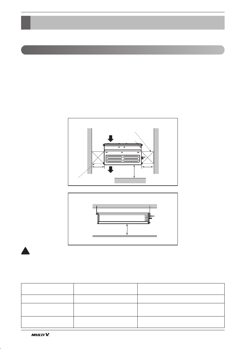
Selection of the best location
Install the air conditioner in the location that satisfies the following conditions.
• The place shall easily bear a load exceeding four times the indoor unit’s weight.
• The place shall be able to inspect the unit as the figure.
• The place where the unit shall be leveled.
•
The place shall allow easy water drainage.
• The place shall easily connect with the outdoor unit.
• The place where the unit is not affected by an electrical noise.
• The place where air circulation in the room will be good .
• There should not be any heat source or steam near the unit.
Top view
[Unit: mm(inch)]
Air inlet vents
Inspection hole(1)
600(23-5/8) x 600(23-5/8)
Control box
1 000
(39-3/8)
Front
600
(23-5/8)
More than 20(25/32)
!
CAUTION
600
(23-5/8)
Air outlet
Inspection hole(2)
600(23-5/8) x 600(23-5/8)
Front view [Unit: mm(inch)]
vents
In case that the unit is installed near the sea, the installation parts may be corroded by
salt, The installation parts (and the unit) should be taken appropriate anti-corrosion
measures.
[Inspection Hole Standard]
Number of
inspection hole
Distance between
false ceiling & actual ceiling
Remarks
1 More than 100 cm (39-3/8 inch) Sufficient space in the ceiling for servicing.
2
Hole size should be more
than the size of IDU.
20 cm (7-7/8 inch) to
100 cm (39-3/8 inch)
Insufficient space. Difficult for servicing
Less than 20 cm (7-7/8 inch) Minimum height for motor replacement.
8 Indoor Unit
Page 9
NOTICE
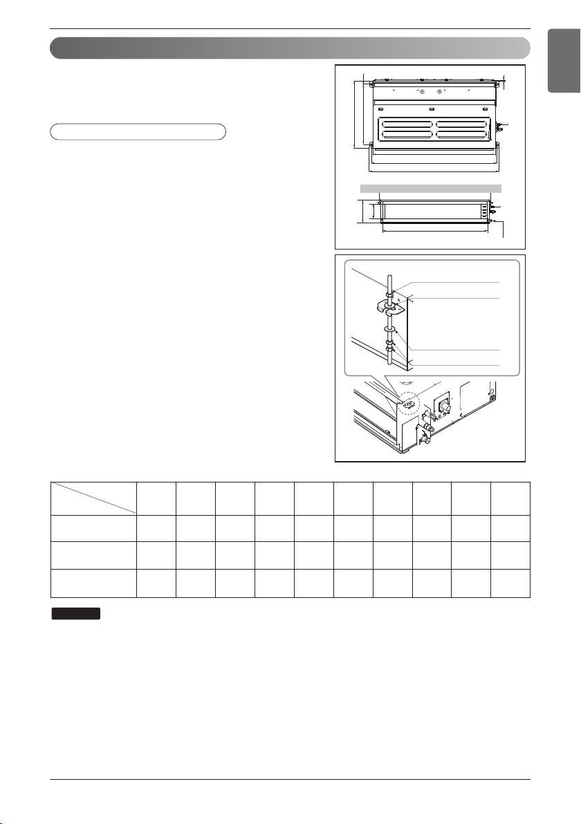
Ceiling dimension and hanging bolt location
n Installation of Unit
Install the unit above the ceiling correctly.
POSITION OF SUSPENSION BOLT
• Apply a joint-canvas between the unit and duct
to absorb unnecessary vibration.
• Install the unit leaning to a drainage hole side
as a figure for easy water drainage.
• A place where the unit will be leveled and that
can support the weight of the unit.
A place where the unit can withstand its vibration.
•
• A place where service can be easily performed.
E
C
D
I
F
J
A
B
H
Installation
ENGLISH
G
Drain hole
Dimension
Chassis name
M1
M2
M3
W3/8 or M10 Nut
W3/8 or M10 washer
W3/8 or M10 washer
W3/8 or M10 Nut
A B C D E F G H I J
933.4
(36-3/4)
1 283.4
(50-17/32)
(52-1/32)
1 283.4
(50-17/32)
(52-1/32)
971.69
(38-1/4)
1 321.6
1 321.6
619.2
(24-3/8)
619.2
(24-3/8)
619.2
(24-3/8)
719.6
(28-11/32)
45.2
(1-3/4)
700
(27-9/16)30(1-3/16)
700
(27-9/16)30(1-3/16)
269.3
(10-19/32)
270
(10-5/8)
360
(14-3/16)
15.2
(19/32)
15.2
(19/32)
15.2
(19/32)
856.4
(33-23/32)
1 208
(47-9/16)
1 208
(47-9/16)
X 4
X 4
X 4
X 8
Unit:mm(inch)
168.8
(6-21/32)
201.4
(7-15/16)
291.4
(11-15/32)
901.6
(35-1/2)
1 250
(49-7/32)
1 250
(49-7/32)
• Throughly study the following installation locations:
1.
In such places as restaurants and kitchens, considerable amount of oil steam and flour adhere to the fan, the fin of the heat
exchanger, resulting in heat exchange reduction, spraying, dispersing of water drops, etc. In these cases, take the following
actions:
• Make sure that the ventilation fan for smoke-collecting hood on a cooking table has sufficient capacity so that it draws oily
steam which should not flow into the suction of the air conditioner.
Make enough distance from a cooking room to install the air conditioner in such a place where it may not suck in oil steam.
•
2. Avoid installing air conditioner in such circumstances where cutting oil mist or iron powder is in suspension in factories, etc.
3. Avoid places where inflammable gas is generated, flows in, is stored or vented.
4. Avoid places where sulfurous acid gas or corrosive gas is generated.
5. Avoid places near high frequency generators.
Installation Manual 9
Page 10

Installation
Indoor Unit Installation
• Select and mark the position for fixing bolts.
Drill the hole for set anchor on the face of ceiling.
•
• Insert the set anchor and washer onto the
suspension bolts for locking the suspension
bolts on the ceiling.
Mount the suspension bolts to the set anchor firmly.
•
• Secure the installation plates onto the
suspension bolts (adjust level roughly) using
nuts, washers and spring washers.
Old building New building
1 Set anchor
2 Plate washer
3 Spring washer
!
CAUTION
Tighten the nut and bolt to prevent unit
4 Nut
5 Suspension
bolts
falling.
Wiring Connection
Connect the wires to the terminals on the control board individually according to the outdoor unit connection.
• Ensure that the color of the wires of outdoor unit and the terminal No. are the same as those of indoor
unit respectively.
Outdoor UnitIndoor Unit
GND 12V
Terminal Block Indoor
L(L1) N(L2)
GN/YL
Indoor Power Input
Terminal Block Indoor
YL RD BK A B
Wired Remote
Controller
INTERNETIDUODU
- -----ABAB
DRY2DRY1
!
WARNING
Make sure that the screws of the terminal are free from looseness.
Clamping of cables
1) Arrange 2 power cables on the control panel.
2) First, fasten the steel clamp with a screw to the inner boss of control panel.
3) For the cooling model, fix the other side of the clamp with a screw strongly. For the heat pump
model, put the 0.75 mm
2
(AWG18) cable(thinner cable) on the clamp and tighten it with a plastic
clamp to the other boss of the control panel.
!
CAUTION
The Power cord connected to the unit should be selected according to the following
specifications.
10 Indoor Unit
Page 11

Installation
Connection method of the connecting cable
• Open the control box cover and connect the remote controller cables, transmission cables and indoor
power cables.
• Control box cover is consist of one panel.
ENGLISH
Control box cover can be separated from main body
• Separate whole cover(when access from bottom of the product).
Remove screws on the bottom panel and grab the both panel with two hands and pull down the whole
cover.
Installation Manual 11
Page 12

Installation
Power Supply
High Voltage
(208/230V)
TransmissionWired Remote
Controller
YL RD BK A B
L(L1) N(L2)
GN/YL
Conduit Hole
Conduit
Conduit panel
Lock nut
Indoor power cable
Remote controller cable and
transmission cable between the
indoor unit and the outdoor unit
After remove the control box cover, insert cables onto the bush and conduit and then connect at
terminal block.
INSULATION, OTHERS
THERMAL INSULATION
INDOOR UNIT
Liquid pipe
Union for gas pipe
12 Indoor Unit
Insulate the joint and tubes completely.
All thermal insulation must comply with local requirement.
Refrigerant pipe and thermal
insulation(Local supply)
Clamp for insulation
(Local supply)
Insulation
(Local supply)
Thermal insulator for refrigerant pipe
(Local supply)
Hose clip for thermal insulator(Local supply)
Make sure that there is no clearance here.
Thermal insulator for
piping(Local supply)
Overlap with thermal
insulator for piping.
Page 13

Installation
Round pressure terminal
Power wire(Ground wire)
ENGLISH
!
CAUTION
The connecting cable connected to the indoor and outdoor unit should be complied with the
following specifications (This equipment shall be provided with a cord set complying with the
national regulation).
Unit: mm (inch)
10(3/8) ± 3(1/8)
30(1-3/8) ± 5(3/16)
GN/YL
20(25/32)
AWG18
If the supply cord is damaged, it must be replaced by a special cord or assembly available from
the manufacturer of its service agent.
u Precautions when laying power and ground wiring
Use round pressure terminals for connections to the power terminal block.
When laying ground wiring, you must use round pressure terminals.
When none are available, follow the instructions below.
• Do not connect wiring of different thicknesses to the power terminal block. (Slack in the power wiring
may cause abnormal heat.)
• When connecting wiring which is the same thickness, do as shown in the figure below.
• For wiring, use the designated power wire and connect firmly, then secure to prevent outside pressure
being exerted on the terminal block.
• Use an appropriate screwdriver for tightening the terminal screws. A screwdriver with a small head will
strip the head and make proper tightening impossible.
• Over-tightening the terminal screws may break them.
Installation Manual 13
Page 14

Installation
Air filters
Air outlet vents
Flaring work
• Firmly hold copper pipe in a bar with the dimension shown in below table table below.
• Carry out flaring work with the flaring tool.
Pipe diameter
Inch (mm)
A Inch (mm)
Wing nut type
Clutch type
Ø 1/4 (Ø 6.35) 0.04~0.05 (1.1~1.3)
Ø 3/8 (Ø 9.52) 0.06~0.07 (1.5~1.7)
Ø 1/2 (Ø 12.7) 0.06~0.07 (1.6~1.8)
Ø 5/8 (Ø 15.88) 0.06~0.07 (1.6~1.8)
0~0.02
(0~0.5)
Ø 3/4 (Ø 19.05) 0.07~0.08 (1.9~2.1)
Thickness
Inch (mm)
0.03 (0.7)
0.03 (0.8)
0.03 (0.8)
0.04 (1.0)
0.04 (1.0)
<Wing nut type>
Bar
"A"
Copper pipe
Checking the Drainage
1. Remove the Air Filter.
2. Check the drainage.
• Spray one or two glasses of water upon the
evaporator.
• Ensure that water flows drain hose of
indoor unit without any leakage.
<Clutch type>
14 Indoor Unit
!
CAUTION
1. Install declination of the indoor unit is very important for the drain of the duct type air
conditioner.
2. Minimum thickness of the insulation for the connecting pipe shall be 5 mm(3/16 inch).
Front of view
• The unit must be horizontal or declined to the drain hose connected when finished installation.
Ceiling
1 mm (1/32 inch) ~ 3 mm (1/8 inch)
Drainage hole
Page 15

Indoor Unit Drain Piping
Maintenance
drain port
Upward
routing
not allowed
Pipe clamp
Indoor unit
1/50~1/100
Max 700mm
(27-9/16 inch)
Feed water
Drain Pump
Drain pan
Flexible drain hose
(accessory)
Main
drain pipe
Glue the joint
Drain
port
Drain hose connection
Use the clip (accessory)
1/50~1/100 slope
Hanger distance
1 m (39-3/8 inch)~15 m (590-9/16 inch)
Hanger Bracket
Max 700 mm
(27-9/16 inch)
Flexible drain hose
Insulation
Metal
clamp
Max 300 mm (11-13/16 inch)Max 300 mm (11-13/16 inch)Max 300 mm (11-13/16 inch)
•
Drain piping must have down-slope (1/50 to 1/100): be sure
not to provide up-and-down slope to prevent reversal flow.
• During drain piping connection, be careful not to exert
extra force on the drain port on the indoor unit.
• The outside diameter of the drain connection on the
indoor unit is 32 mm (1-1/8 inch).
Piping material: Polyvinyl chloride pipe inner
diometes Ø 25 mm (31/32 inch) and pipe fittings
• Be sure to install heat insulation on the drain piping.
Heat insulation material: Polyethylene foam with
thickness more than 8 mm (5/16 inch).
Drain test
The air conditioner uses a drain pump to drain water.
Use the following procedure to test the drain pump operation:
• Connect the main drain pipe to the
exterior and leave it provisionally until the
test comes to an end.
• Feed water to the flexible drain hose and
check the piping for leakage.
• Be sure to check the drain pump for
normal operation and noise when
electrical wiring is complete.
• When the test is complete, connect the
flexible drain hose to the drain port on the
indoor unit.
Installation
ENGLISH
!
CAUTION
The supplied flexible drain hose should not be strained. A strained hose may cause
leakage of water.
Installation Manual 15
Page 16

Installation
!
CAUTION
After the confirmation of the above conditions, prepare the wiring as follows:
1) Never fail to have an individual power specialized for the air conditioner. As for the
method of wiring, be guided by the circuit diagram posted on the inside of control
box cover.
2) Provide a circuit breaker switch between power source and the unit.
3) The screws which fasten the wiring in the casing of electrical fittings are liable to
come loose from vibrations to which the unit is subjected during the course of
transportation. Check them and make sure that they are all tightly fastened. (If they
are loose, it could give rise to burn-out of the wires.)
4) Specification of power source
5) Confirm that electrical capacity is sufficient.
6) Be sure that the starting voltage is maintained at more than 90 percent of the rated
voltage marked on the name plate.
7) Confirm that the cable thickness is as specified in the power sources specification.
(Particularly note the relation between cable length and thickness.)
8) Never fail to equip a leakage breaker where it is wet or moist.
9) The following troubles would be caused by voltage drop-down.
• Vibration of a magnetic switch, damage on the contact point, fuse breaking, disturbance
by the normal function of an overload protection device.
• Proper starting power is not given to the compressor.
HAND OVER
Teach the customer the operation and maintenance procedures, using the operation manual.
(air filter cleaning, temperature control, etc.)
16 Indoor Unit
Page 17

Installation
DIP Switch Setting
1. Indoor Unit
Function Description Setting Off Setting On Default
SW1 Communication N/A (Default) - - Off
SW2 Cycle N/A (Default) - - Off
SW3 Group Control
Dry Contact
SW4
Mode
SW5 Installation
SW6 Heater linkage N/A - - Off
Ventilator
linkage
Vane selection
SW7
(Console)
Region
selection
SW8 Etc. Spare - - Off
Selection of Master or
Slave
Selection of Dry
Contact Mode
Fan continuous
operation
Selection of Ventilator
linkage
Selection of up/down
side Vane
Selection tropical
region
Master Slave Off
Wired/Wireless remote
controller
selection of Manual or Auto
operation Mode
Continuous operation
Removal
Linkage Removal Working
Up side + Down side Vane
General model
Auto Off
- Off
Up side Vane
Only
Tropical
model
ENGLISH
Off
!
CAUTION
For Multi V Models, DIP switch 1, 2, 6, 8 must be set OFF.
2. Outdoor Unit
In case that the products meet specific conditions, “Auto addressing” function can start automatically
with the improved speed by turning the DIP switch #3 of the outdoor unit and resetting the power.
※ Specific conditions:
- All names of the indoor units are ARNU****4.
- The serial number of Multi V super IV (outdoor units) is after October 2013.
DIP switch 7 segment
Outdoor Unit PCB Outdoor Unit DIP Switch
Installation Manual 17
Page 18

Installation
Group Control Setting
!
CAUTION
If you want to use the two setpoint function, you should be installed the both new thermostat and
4 series products.
* Model name of wired remote controller called New thermostat : PREMTC00U
1. Group Control 1
n Wired remote controller 1 + Standard Indoor Units
LGAP Network System
or
GND
Master Slave Slave Slave
Signal
12 V
Display Error Message
Master
Only connect serial signal and
GND lines between indoor units.
n DIP Switch in PCB
¿ Master Setting
- No. 3 Off
¡ Slave Setting
- No. 3 On
Indoor Unit DIP Switch
Some products have no DIP switch on PCB. It is possible to set indoor units to Master or Slave by
using the wireless remote controller instead of DIP switch.
For the details of the setting, please refer to the manual of the wireless remote controller.
18 Indoor Unit
Page 19

Installation
1. It is possible to 16 indoor units(Max.) by one wired remote controller.
ENGLISH
Set only one indoor unit to Master, set the others to Slave.
2. It is possible to connect with every type of indoor units.
3. It is possible to use wireless remote controller at the same time.
4. It is possible to connect with Dry Contact and Central controller at the same time.
- The Master indoor unit is possible to recognize Dry Contact and Central Controller only.
5. In case that any error occurs at indoor unit, the error code is displayed on the wired remote
controller.
It is possible to control the other indoor units except the error units.
h It is possible to connect indoor units since Feb. 2009.
h It can be the cause of malfuctions when there is no setting of master and slave.
h In case of Group Control, it is possible to use following functions.
- Selection of operation, stop or mode
- Temperature setting and room temperature check
- Current time change
- Control of flow rate (High/Middle/Low)
- Reservation settings
It is not possible to use some functions.
2. Group Control 2
n Wired remote controllers + Standard Indoor Units
LGAP Network System
Slave
GND
Signal
12 V
Master
Master
Donʼt connect serial 12 V line
Display Error Message
MasterMaster
or
Slave
h It is possible to control 16 indoor units(Max.) with the master wired remote control.
h Other than those, it is same with the Group Control 1.
Installation Manual 19
Page 20

Installation
3. Group Control 3
n Mixture connection with indoor units and Fresh Air Intake Unit
LGAP Network System
Slave
Display Error Message
GND
Signal
12 V
M
FAU
Master
Master
FAU
Slave
Display Error Message
or
Master
N
Master
h In case of connecting with standard indoor unit and Fresh Air Intake Unit, separate Fresh
Air Intake Unit with standard units. (N, M ≤ 16) (Because setting temperature are different.)
h Other than those, it is same with Group Control 1.
FAU
Standard Standard
FAU FAU
FAU
Standard Standard
20 Indoor Unit
* FAU : Fresh Air Intake Unit
Standard: Standard Indoor Unit
Page 21

4. 2 Remote Control
n Wired remote controller 2 + Indoor unit 1
Installation
ENGLISH
LGAP Network System
Slave
GND
Signal
12 V
Master
Master
Display Error Message
Slave
Slave
or
Slave
1. It is possible to connect two wired remote controllers (Max.) with one indoor unit.
Set only one indoor unit to Master, set the others to Slave.
Set only one wired remote controller to Master, set the others to Slave.
2. Every types of indoor unit is possible to connect two remote controller.
3. It is possible to use wireless remote controller at the same time.
4. It is possible to connect with Dry Contact and Central controller at the same time.
5. In case that any error occurs at indoor unit, the error code is displayed on the wired
remote controller.
6. There isnʼt limits of indoor unit function.
5. Accessories for group control setting
It is possible to set group control by using below accessories.
Indoor unit 2 EA +Wired remote controller 1 EA
h
PZCWRCG3 cable used for connection
Master
Slave
PZCWRCG3
Master
Indoor unit 1 EA +Wired remote controller 2 EA
h
PZCWRC2 cable used for connection
PZCWRC2
Master Slave
Installation Manual 21
Page 22

Installation
Airborne Noise Emission
The A-weighted sound pressure emitted by this product is below 70 dB.
** The noise level can vary depending on the site.
The figures quoted are emission level and are not necessarily safe working levels. Whilst there is a
correlation between the emission and exposure levels, this cannot be used reliably to determine
whether or not further precautions are required. Factor that influence the actual level of exposure of the
workforce include the characteristics of the work room and the other sources of noise, i.e. the number
of equipment and other adjacent processes and the length of time for which an operator exposed to the
noise. Also, the permissible exposure level can vary from country to country. This information, however,
will enable the user of the equipment to make a better evaluation of the hazard and risk.
Limiting concentration
Limiting concentration is the limit of Freon gas concentration where immediate measures can be
taken without hurting human body when refrigerant leaks in the air. The limiting concentration shall
be described in the unit of kg/m3(lbs/ft3) (Freon gas weight per unit air volume) for facilitating
calculation
Limiting concentration: 0.44 kg/m3(0.028 lbs/ft3)(R410A)
n Calculate refrigerant concentration
Refrigerant concentration =
Total amount of replenished refrigerant in refrigerant facility (kg(lb(s)))
Capacity of smallest room where indoor unit is installed (m
3
(ft3))
22 Indoor Unit
Page 23

How to Set E.S.P?
How to Set E.S.P?
ENGLISH
M1 Chassis : 7, 9, 12, 15, 18 k
Setting
value
100 20.9(737) 19.3(681) 16.9(598) 14.4(509) 9.7(344)
105 23.1(816) 21.4(755) 18.9(666) 16.1(570) 12.0(423) 7.4(260)
110 24.4(860) 22.9(809) 20.7(731) 18.5(652) 15.2(538) 9.9(351)
115 24.3(858) 22.3(786) 20.2(715) 17.6(621) 14.3(506) 9.5(334)
120 23.8(841) 21.9(775) 19.5(687) 16.5(581) 12.8(452) 10.0(352)
125 23.6(833) 21.5(761) 19.1(675) 16.1(569) 14.2(501)
130 25.7(906) 23.4(828) 21.0(742) 18.2(644) 16.7(590)
135 25.2(890) 23.2(819) 20.8(735) 19.4(684)
140 25.1(888) 23.2(820) 21.8(770)
2.5(0.10) 4(0.16) 6(0.24) 8(0.31) 10(0.39) 12(0.47) 14(0.55) 15(0.59)
60 6.6(233)
65 8.9(315)
70 11.3(400) 8.1(285)
75 12.9(455) 10.4(368) 6.1(216)
80 14.7(520) 12.5(440) 8.4(296)
85 16.4(580) 14.3(504) 10.4(366)
90 18.1(640) 16.1(569) 12.9(454) 8.9(314)
95 19.7(696) 17.9(631) 15.0(530) 11.7(413)
Static Pressure (mmAq(in wg))
M1 Chassis : 24 k
Setting
value
100 25.9(916) 24.3(858) 22.6(798) 20.5(723) 17.9(631) 14.3(504) 11.8(418)
105 25.5(900) 24.0(848) 22.2(784) 20.1(710) 17.5(618) 15.9(560)
110 25.3(894) 23.9(844) 22.3(786) 20.2(713) 18.8(664)
115 25.0(884) 23.5(830) 21.6(764) 20.6(728)
Note: 1. The above table shows the correlation between the air rates and E.S.P.
2.5(0.10) 4(0.16) 6(0.24) 8(0.31) 10(0.39) 12(0.47) 14(0.55) 15(0.59)
60 16.2(572) 14.4(510)
65 17.7(625) 15.8(558)
70 18.9(667) 17.4(615) 14.6(515)
75 20.3(717) 18.9(668) 16.7(588) 14.0(494)
80 21.8(770) 20.1(710) 17.9(633) 15.7(554) 12.5(440)
85 23.2(819) 21.8(769) 19.6(692) 17.4(616) 14.3(506)
90 24.7(872) 23.4(825) 21.4(755) 19.5(687) 16.9(598) 13.8(487)
95 25.8(911) 24.6(868) 22.8(805) 21.0(742) 18.6(658) 15.7(553) 10.7(378)
2. Make sure to check and adjust E.S.P (external static pressure) value after the
installation of the product. Otherwise, there is a risk of weak cooling/heating and
condensed water discharge/drop.
Static Pressure (mmAq(in wg))
(Unit: CMM)
(Unit: CMM)
Installation Manual 23
Page 24

How to Set E.S.P?
M2 (7k~24k)
(Unit: CMM(CFM))
Setting
Value
100 33.1(1 168) 28.7(1 013) 20.8(734) 9.2(325) 3.8(135)
105 35.9(1 267) 31.7(1 119) 24.1(851) 17.5(618) 6.7(238)
110 38.6(1 363) 34.7(1 225) 30.5(1 077) 22.2(784) 11.5(406) 5.5(195)
115 40.1(1 416) 37.8(1 334) 33.8(1 193) 27.9(985) 20.2(713) 9.1(321)
120 39.1(1 380) 37.1(1 310) 31.4(1 108) 24.6(868) 17.9(632) 7.5(263)
125 38.5(1 358) 35.0(1 236) 30.1(1 063) 21.2(748) 11.0(389) 6.8(235)
130 37.1(1 310) 32.0(1 130) 27.6(974) 15.6(551) 10.0(353)
135 36.8(1 298) 31.5(1 113) 24.3(857) 16.2(572)
140 40.5(1 431) 35.9(1 267) 29.8(1 052) 22.4(792)
145 39.9(1 407) 34.9(1 233) 27.8(980)
150 39.4(1 391) 34.2(1 207)
155 37.1(1 309)
4(0.16) 6(0.24) 8(0.31) 10(0.39) 12(0.47) 14(0.55) 16(0.59) 18(0.71)
75 15.0(530)
80 19.0(672) 7.5(267)
85 24.9(879) 13.7(486) 4.9(173)
90 27.6(974) 20.4(720) 7.8(276)
95 30.4(1 073) 24.4(861) 15.7(554) 5.2(182)
Static Pressure (mmAq(in wg))
M2 (28k~42k)
(Unit: CMM(CFM))
Setting
Value
100 28.6(1 010) 23.3(823)
105 31.4(1 110) 26.4(931) 19.6(691)
110 34.2(1 208) 29.9(1 056) 24.1(854)
115 36.6(1 292) 32.7(1 153) 28.8(1 016) 21.8(765)
120 39.2(1 383) 35.7(1 260) 31.8(1 121) 26.2(926) 19.6(692)
125 41.7(1 473) 38.5(1 358) 34.8(1 227) 30.8(1 087) 24.3(857)
130 44.0(1 554) 41.2(1 456) 37.7(1 332) 34.1(1 203) 29.0(1 023) 22.3(787)
135 43.8(1 545) 40.7(1 437) 37.3(1 318) 32.6(1 150) 27.5(971) 20.5(723)
140 43.5(1 534) 40.4(1 426) 37.2(1 313) 32.6(1 151) 25.8(909) 19.9(701)
145 43.4(1 533) 41.6(1 468) 37.4(1320) 30.7(1 084) 24.6(868)
150 43.4(1 532) 42.3(1 493) 35.4(1 249) 29.4(1 036)
155 43.7(1 543) 37.5(1 324) 32.7(1 155)
Note: 1. The above table shows the correlation between the air rates and E.S.P.
4(0.16) 6(0.24) 8(0.31) 10(0.39) 12(0.47) 14(0.55) 16(0.59) 18(0.71)
90 23.0(812)
95 25.9(914) 19.1(676)
2. Make sure to check and adjust E.S.P (external static pressure) value after the
installation of the product. Otherwise, there is a risk of weak cooling/heating and
condensed water discharge/drop.
Static Pressure (mmAq(in wg))
24 Indoor Unit
Page 25

How to Set E.S.P?
M3 (28k~54k)
(Unit: CMM(CFM))
Setting
Value
Note: 1. The above table shows the correlation between the air rates and E.S.P.
4(0.16) 6(0.24) 8(0.31) 10(0.39) 12(0.47) 14(0.55) 16(0.59) 18(0.71) 20(0.79)
70 25.2(891)
75 30.4(1 074) 21.4(756)
80 35.0(1 235) 27.1(959) 18.5(654)
85 39.8(1 404) 35.4(1 250) 24.6(869)
90 44.3(1 562) 40.1(1 416) 31.5(1 111) 22.7(800)
95 49.3(1 741) 44.8(1 581) 36.8(1 300) 28.8(1 017) 21.4(754)
100 53.0(1 872) 49.4(1 744) 44.6(1 574) 35.4(1 251) 27.7(978)
105 57.2(2 020) 54.1(1 910) 49.2(1 737) 43.0(1 518) 35.0(1 234) 26.5(935)
110 58.8(2 076) 53.9(1 903) 47.9(1 691) 42.4(1 497) 33.8(1 193) 24.3(858) 14.8(522)
115 58.6(2 069) 52.9(1 867) 47.8(1 687) 42.5(1 500) 31.4(1 108) 20.3(717) 18.3(646)
120 57.8(2 040) 53.1(1 874) 48.2(1 701) 39.2(1 384) 30.2(1 066) 24.6(868)
125 54.2(1 913) 49.4(1 744) 43.1(1 520) 36.7(1 296) 33.1(1 168)
130 54.6(1 927) 52.7(1 860) 48.6(1 714) 44.4(1 567) 39.6(1 398)
135 50.2(1 772) 45.2(1 596)
2. Make sure to check and adjust E.S.P (external static pressure) value after the
installation of the product. Otherwise, there is a risk of weak cooling/heating and
condensed water discharge/drop.
Static Pressure (mmAq(in wg))
ENGLISH
Installation Manual 25
Page 26

26 Indoor Unit
Page 27

US
CANADA
Please call the installing contractor of your product, as warranty service will be provided
by them.
Service call Number # : (888) LG Canada, (888) 542-2623
Numéro pour les appels de service : LG Canada, 1-888-542-2623
 Loading...