


LG AR-DR12-07A, AR-DR12-12A, AR-DR12-10A, AR-DR22-15A, AR-DR22-20A Installation And Operation Manual
...
ROOFTOP DEDICATED
OUTDOOR AIR SYSTEM (DOAS)
VX MODELS
INSTALLATION AND OPERATION MANUAL
Base Rooftop DOAS
800 to 5750 CFM
Energy Recovery Wheel Rooftop DOAS
900 to 9550 CFM
PROPRIETARY DATA NOTICE
This document, as well as all reports, illustrations, data, information,
and other materials are the property of LG Electronics U.S.A., Inc., and are
disclosed by LG Electronics U.S.A., Inc. only in confidence.
Do not throw away, destroy, or lose this manual.
Please read carefully and store in a safe place for future reference.
Content familiarity is required for proper installation.
The instructions included in this manual must be followed to prevent product malfunction, property damage, injury, or death to the user or
other people. Incorrect operation due to ignoring any instructions will cause harm or damage. The level of seriousness is classified by the
symbols described by the summary list of safety precautions on page 4.
For more technical materials such as submittals, catalogs, engineering
manuals, and forms, visit www.lghvac.com.
For continual product development, LG Electronics U.S.A., Inc. reserves the right to change specifications without notice.
© LG Electronics U.S.A., Inc.

TABLE OF CONTENTS
SAFETY PRECAUTIONS ....................................................................... 4
Unit Nomenclature ................................................................................. 8
GENERAL DATA ..................................................................................... 9
Base Rooftop DOAS ............................................................................ 9
Energy Recovery Wheel Rooftop DOAS ............................................11
Refrigerant Safety ................................................................................ 13
Receiving Guidelines .......................................................................... 14
Inspection and Maintenance .............................................................. 15
Subassemblies .................................................................................... 17
Installation ............................................................................................ 19
Outdoor Air Hood Assembly .............................................................. 25
Piping Installation ................................................................................ 32
Electrical Information .......................................................................... 34
Control Center Components .............................................................. 35
Component Operation ......................................................................... 36
Optional Component Operation ......................................................... 37
Factory-Installed Refrigeration System Components ...................... 41
Start Up Unit ......................................................................................... 43
Start Up Checklist ................................................................................ 46
Indirect Gas Fired Furnaces ............................................................... 64
Typical Furnace, Electrical, and Control Components ....................... 69
Gas Fired Burner Turndown .............................................................. 70
Installation of Venting for Outdoor Units ............................................ 71
Installation of Venting for Indoor Units ............................................... 72
Venting Methods ................................................................................ 73
Standard Indoor Venting Installation .................................................. 74
Concentric Venting Installation .......................................................... 75
Two Pipe Venting Installation - Horizontal ......................................... 78
Two Pipe Venting Installation - Vertical .............................................. 79
Sequence of Operation ...................................................................... 82
Performance Data ............................................................................. 83
Furnace Start Up ............................................................................... 84
Troubleshooting - Ignition Controller .................................................. 87
Troubleshooting - 4:1 Modulating Furnace ........................................ 89
Troubleshooting - 4:1 or High Turndown Modulating Furnace 94
Reference - Controls ......................................................................... 98
Maintenance ...................................................................................... 99
Maintenance Log ............................................................................. 100
CONTROLLER .................................................................................... 102
Overview .......................................................................................... 102
AC Smart Setup ................................................................................114
Sequences of Operation ...................................................................117
Set-Points Data Tables .................................................................... 129
Network Settings Data Tables .......................................................... 136
Alarm Data ....................................................................................... 141
BACnet and MODBUS Points ......................................................... 145
Unit Status Modes ........................................................................... 157
LonTalk Points ................................................................................. 158
Start Up Components .......................................................................... 47
Optional Energy Wheel ....................................................................... 50
Troubleshooting - Alarms ................................................................... 53
Troubleshooting - Unit ........................................................................ 54
Troubleshooting - Refrigeration Circuit ............................................ 55
Routine Maintenance .......................................................................... 59
Reference - Venting Connection Locations ...................................... 62
AHRI Rating Conditions ...................................................................... 63
Due to our policy of continuous product innovation, some specifications may change without notification.
©LG Electronics U.S.A., Inc., Englewood Cliffs, NJ. All rights reserved. “LG” is a registered trademark of LG Corp.
3
WARNING
DANGER
DANGER
WARNING
CAUTION
SAFETY PRECAUTIONS
The instructions below must be followed to prevent product malfunction, property damage, injury or death to the user or other people. Incorrect operation due to ignoring any instructions will cause harm or damage. The level of seriousness is classified by the symbols below.
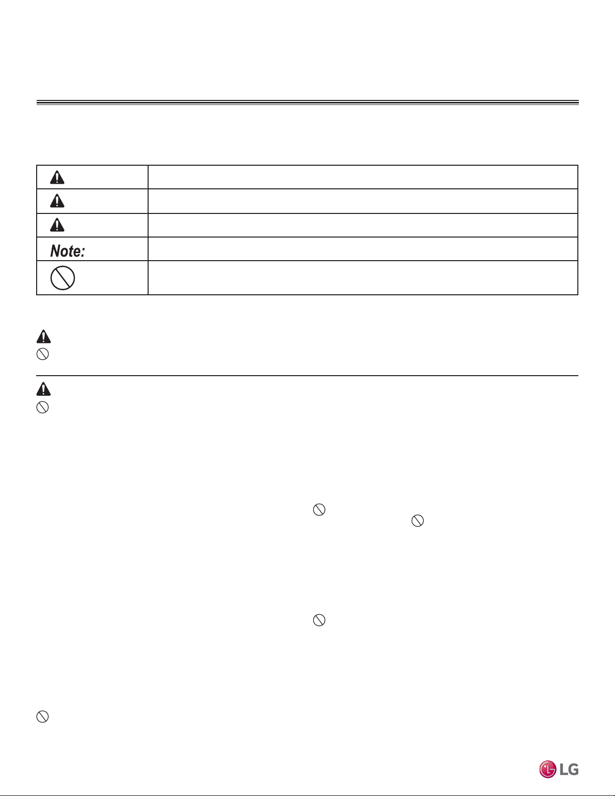
TABLE OF SYMBOLS
This symbol indicates an imminently hazardous situation which, if not avoided, will result in death or serious injury.
This symbol indicates a potentially hazardous situation which, if not avoided, could result in death or serious injury.
This symbol indicates a potentially hazardous situation which, if not avoided, may result in minor or moderate injury.
This symbol indicates situations that may result in equipment or property damage accidents only.
This symbol indicates an action that should not be performed.
INSTALLATION
Don’t use or store ammable gas or combustibles near the unit.
There is risk of re, explosion, and physical injury or death.
Do not install or remove the unit by yourself
(end-user). Ask the dealer or an LG trained technician to
install the unit.
Improper installation by the user may result in water leakage, re,
explosion, electric shock, physical injury or death.
Installation, startup, and service must be performed by a
qualied installer, service agency, or gas supplier.
Improper installation, adjustment, service, maintenance, or alteration
can cause personal injury or loss of life.
For replacement of an installed unit, always contact a
trained service provider.
There is risk of re, electric shock, explosion, and physical injury or
death.
Rooftop Dedicated Outdoor Air System Installation Manual
Periodically check that the unit is not damaged.
There is risk of explosion, physical injury, or death.
Replace all control box and panel covers.
If cover panels are not installed securely, dust, water and animals may
enter the unit, causing re, electric shock, and physical injury or death.
Always check for system refrigerant leaks after the unit has
been installed or serviced.
Exposure to high concentration levels of refrigerant gas may lead to
illness or death.
Do not install the unit using defective hanging, attaching,
or mounting hardware.
There is risk of physical injury or death.
Wear protective gloves when handling equipment.
Sharp edges may cause personal injury.
Dispose of the packing materials safely.
• Packing materials, such as nails and other metal or wooden parts
may cause puncture wounds or other injuries.
• Tear apart and throw away plastic packaging bags so that children
may not play with them and risk suffocation and death.
Do not install the unit in any location exposed to open
ame or extreme heat. Do not touch the unit with wet
hands.
There is risk of re, electric shock, explosion, and physical injury or
death.
Install the unit considering the potential for earthquakes.
Improper installation may cause the unit to fall, resulting in physical
injury or death.
Do not change the settings of the protection devices.
If the pressure switch, thermal switch, or other protection device is
shorted and forced to operate improperly, or parts other than those spec-
ied by LG are used, there is risk of re, electric shock, explosion, and
physical injury or death.
If the unit is installed in a small space, take measures to
prevent the refrigerant concentration from exceeding safety
limits in the event of a refrigerant leak.
Consult the latest edition of ASHRAE (American Society of Heating,
Refrigerating, and Air Conditioning Engineers) Standard 15. If the refrigerant leaks and safety limits are exceeded, it could result in personal
injuries or death from oxygen depletion.
4
Due to our policy of continuous product innovation, some specifications may change without notification.
©LG Electronics U.S.A., Inc., Englewood Cliffs, NJ. All rights reserved. “LG” is a registered trademark of LG Corp.
CAUTION
SAFETY PRECAUTIONS
INSTALLATION – CONTINUED
Be very careful when transporting the product.
• Do not attempt to carry the product without assistance.
• Unit must be lifted by all lifting lugs provided at top of unit.
• Spreader bars are required to prevent damage to the cabinet, failure to do so can result in damage that is the installer’s responsibility.
• Failure to follow these directions may result in minor or moderate physical injury.
Installation, startup, and service must be performed by a
qualied installer, service agency, or gas supplier.
Improper installation, adjustment, service, maintenance, or alteration can
cause property damage.
Properly insulate all cold surfaces to prevent “sweating.”
Cold surfaces such as uninsulated pipe can generate condensate that
may drip and cause a slippery oor condition and/or water damage to
walls.
Do not use the product for special purposes such as preserving foods, works of art, wine coolers, or other precision
air conditioning applications.
There is risk of property damage.
Do not make refrigerant substitutions. Use R410A only.
If a different refrigerant is used, or air mixes with original refrigerant, the
unit will malfunction and become damaged.
Do not install the unit in a noise sensitive area.
Take appropriate actions at the end of HVAC equipment life
to recover, recycle, reclaim or destroy R410A refrigerant according to applicable U.S. Environmental Protection Agency
(EPA) rules.
Install the unit in a safe location where no one can step on or
fall onto it.
There is risk of unit and property damage.
Install the drain trap to ensure adequate drainage.
There is a risk of water leakage and property damage.
Don’t store or use ammable gas / combustibles near the
unit.
There is risk of product failure.
Always check for system refrigerant leaks after the unit has
been installed or serviced.
Low refrigerant levels may cause product failure.
Ductwork and other installed airow restriction devices such
as lters shall not exceed the rated maximum static pressure
limits of the DOAS fan assembly.
Doing so may cause product malfunction.
Safety Precautions
Due to our policy of continuous product innovation, some specifications may change without notification.
©LG Electronics U.S.A., Inc., Englewood Cliffs, NJ. All rights reserved. “LG” is a registered trademark of LG Corp.
5
DANGER
WARNING
SAFETY PRECAUTIONS
WIRING
High voltage electricity is required to operate this system.
Adhere to the National Electrical Codes and these
instructions when wiring.
Improper connections and inadequate grounding can cause accidental
injury or death.
Always ground the unit following local, state, and National
Electrical Codes.
The information contained in this manual is intended for use
by an experienced, trained electrician familiar with the U.S.
National Electric Code (NEC) who is equipped with the proper
tools and test instruments.
Failure to carefully read and follow all instructions in this manual can
result in injury or death.
Ensure the unit is connected to a dedicated power source
that provides adequate power.
If the power source capacity is inadequate or the electric work is not
performed properly, it may result in re, electric shock, physical injury or
death.
Turn the power o at the nearest disconnect before servicing
the equipment.
Electric shock can cause physical injury or death.
Properly size all circuit breakers or fuses.
There is risk of re, electric shock, explosion, physical injury or death.
Refer to local, state, and federal codes, and use power wires
of sucient current capacity and rating.
Wires that are too small may generate heat and cause a re and physical injury or death.
Secure all eld wiring connections with appropriate wire
strain relief.
Improperly securing wires will create undue stress on equipment power
lugs. Inadequate connections may generate heat, cause a re and
physical injury or death.
Properly tighten all power connections.
Loose wiring may overheat at connection points, causing a re, physical
injury or death.
The information contained in this manual is intended for use by an experienced, trained electrician familiar with the U.S.
National Electric Code (NEC) who is equipped with the proper tools and test instruments.
Failure to carefully read and follow all instructions in this manual can result in equipment malfunction or property damage.
Rooftop Dedicated Outdoor Air System Installation Manual
6
Due to our policy of continuous product innovation, some specifications may change without notification.
©LG Electronics U.S.A., Inc., Englewood Cliffs, NJ. All rights reserved. “LG” is a registered trademark of LG Corp.
OPERATION
DANGER
WARNING
CAUTION
SAFETY PRECAUTIONS
Do not provide power to or operate the unit if it is ooded
or submerged.
There is risk of re, electric shock, physical injury or death.
Use a dedicated power source for this product.
There is risk of re, electric shock, physical injury or death.
Do not allow water, dirt, or animals to enter the unit.
There is risk of re, electric shock, physical injury or death.
Do not touch refrigerant piping during or after operation.
It can cause burns or frostbite.
Do not operate the unit with the panel(s) or protective
cover(s) removed; keep ngers and clothing away from
moving parts.
The rotating, hot, cold, and high-voltage parts of the unit can cause
physical injury or death.
Do not operate the disconnect switch with wet hands.
There is risk of re, electric shock, physical injury or death.
If refrigerant gas leaks out, ventilate the area before operating the unit.
If the unit is mounted in an enclosed, low-lying, or poorly ventilated area
and the system develops a refrigerant leak, it may cause re, electric
shock, explosion, physical injury or death.
Periodically check power cable and connection for damage.
Cable must be replaced by the manufacturer, its service agent, or similar
qualied persons in order to avoid physical injury and / or electric shock.
Securely attach the electrical cover to the unit.
Non-secured electrical covers can result in burns or electric shock due to
dust or water in the service panel.
Ensure no power is connected to the unit other than as
directed in this manual. Remove power from the unit before
removing or servicing the unit.
There is risk of unit failure, re, electric shock, physical injury or death.
Safety Precautions
To avoid physical injury, use caution when cleaning or servicing the air conditioner.
Clean up the site after installation is nished, and check
that no metal scraps, screws, or bits of wiring have been left
inside or surrounding the unit.
Do not use this equipment in mission critical or specialpurpose applications such as preserving foods, works of art,
wine coolers or refrigeration.
Provide power to the compressor crankcase heaters at least
twenty-four (24) hours before operation begins.
Starting operation with a cold compressor sump(s) may result in severe
Do not block the inlet or outlet.
Unit may malfunction.
Securely attach the electrical cover to the indoor unit.
Non-secured covers can result in re due to dust or water in the service
panel.
Periodically verify the equipment mounting hardware has not
deteriorated.
If the base collapses, the unit could fall and cause property damage or
product failure.
bearing damage to the compressor(s). Keep the power switch on during
the operational season.
Do not allow water, dirt, or animals to enter the unit.
There is risk of unit failure.
Due to our policy of continuous product innovation, some specifications may change without notification.
©LG Electronics U.S.A., Inc., Englewood Cliffs, NJ. All rights reserved. “LG” is a registered trademark of LG Corp.
7
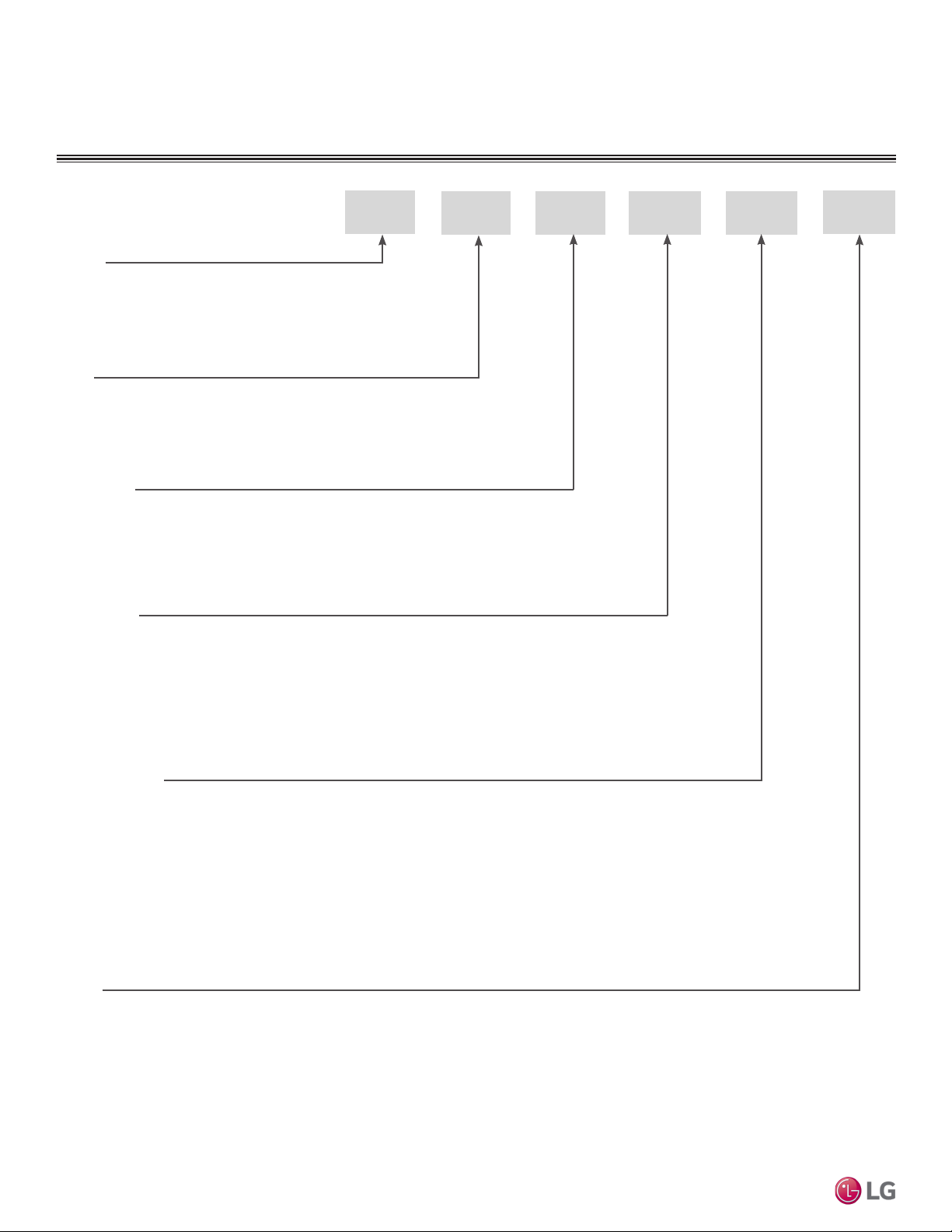
UNIT NOMENCLATURE
Family
AR = Air-Source Packaged Rooftop Unit,
R410A Refrigerant
Type
D = Dedicated Outdoor Air System (DOAS)
ERV Option
R = Base Unit
E = Energy Recovery Wheel
Chassis Size
12 = 112
22 = 212
AR
D R 11 05
A
Cooling Capacity
05 = 5 Tons
07 = 7.5 Tons
10 = 10 Tons
12 = 12.5 Tons
15 = 15 Tons
Rooftop Dedicated Outdoor Air System Installation Manual
17 = 17.5 Tons
Series
A = First Series
8
20 = 20 Tons
25 = 25 Tons
30 = 30 Tons
Due to our policy of continuous product innovation, some specifications may change without notification.
©LG Electronics U.S.A., Inc., Englewood Cliffs, NJ. All rights reserved. “LG” is a registered trademark of LG Corp.
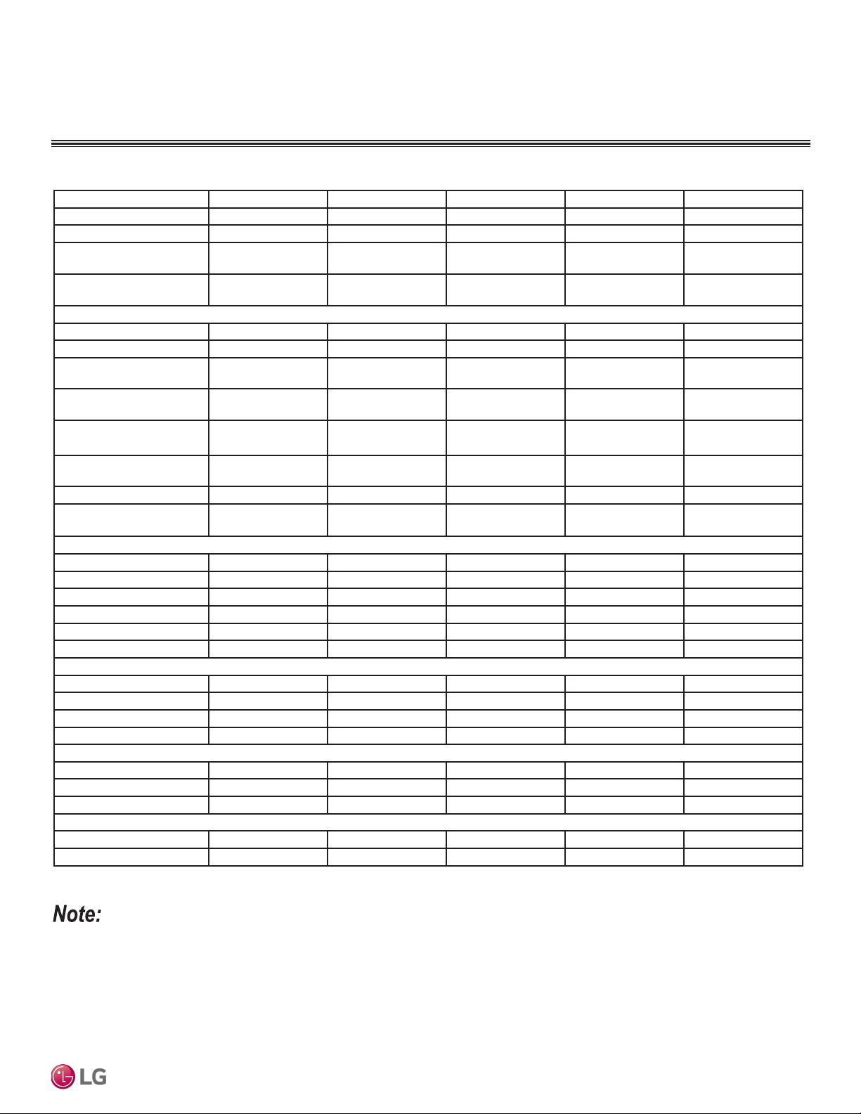
GENERAL DATA
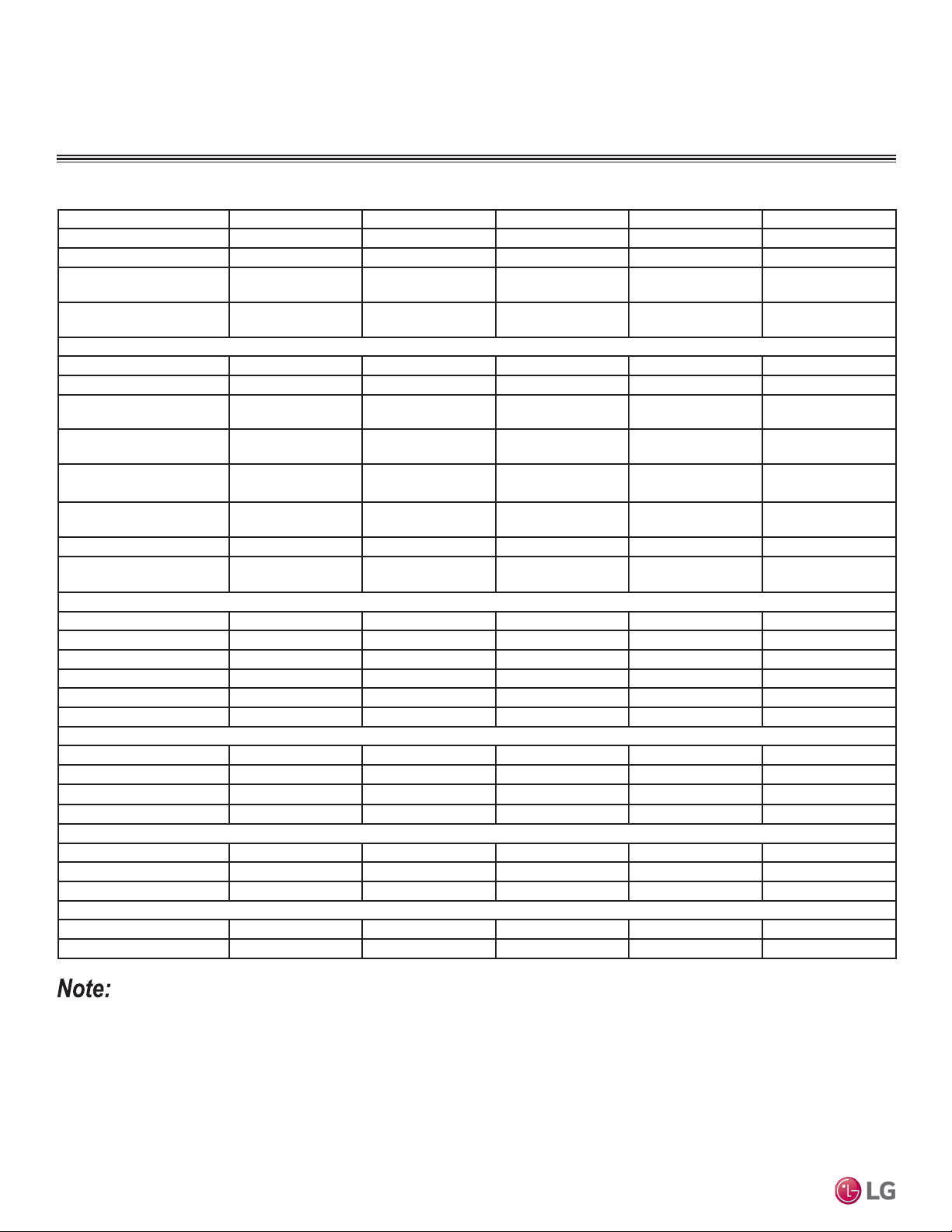
Base Rooftop DOAS
Table 1: Base Rooftop DOAS.
Model No. AR-DR12-05A AR-DR12-07A AR-DR12-10A AR-DR12-12A AR-DR12-15A
Design Airflow (CFM) 980 1500 1800 2250 2900
ESP (in. wg) 2 2 2 2 2
Entering Air Summer
DB / WB (°F)
Entering Air Winter
DB (°F)
Cooling Performance
Coil LAT DB / WB (°F) 54.8/54.7 54.5/54.4 54.5/54 54.9/54.8 54.7/54.5
Unit LAT DB / WB (°F) 93.8 87.2 82.1 81.9 79.9
Total Cooling
Capacity (MBH)
Sensible Cooling
Capacity (MBH)
Hot Gas Reheat Coil
Capacity (MBH)
Evaporator Coil
Depth(Rows)
No. of Compressors 1 1 2 2 2
Compressor Type(s) Digital scroll Digital scroll
Heating
Fuel Natural Gas Natural Gas Natural Gas Natural Gas Natural Gas
Capacity Input (MBH) 100 200 200 250 300
Capacity Output (MBH) 80 160 160 200 240
LAT (°F) 75.6 98.8 82.3 82.3 76.6
Turndown Type Modulating Modulating Modulating Modulating Modulating
Turndown Ratio 4:1 4:1 4:1 4:1 4:1
Supply Fan Data
Fan Quantity 1 1 1 1 1
Wheel Diameter (in.) 14 14 14 14 18
Wheel Speed (RPM) 1809 1996 2133 2376 1716
Motor HP 1 1 1.5 1.5 3
Configuration
Outdoor Air Intake End End End End End
Supply Air Discharge Bottom Bottom Bottom Bottom Bottom
Weight (lbs.) 2253 2325 2384 2487 2646
Filtration
Hood None None None None None
Supply 2" MERV 8 2" MERV 8 2" MERV 8 2" MERV 8 2" MERV 8
95/75 95/75 95/75 95/75 95/75
0 0 0 0 0
68.2 105.4 128.3 155.6 202.9
43.3 66.8 80.3 99.2 128.6
41.3 52.8 53.7 65.6 78.8
4 5 4 6 6
Digital scroll /
Standard scroll
Digital scroll /
Standard scroll
Digital scroll /
Standard scroll
Product Data
• Capacity data above will change if entering air temperatures, leaving air temperatures (LAT), or airflow rates are varied.
• Take appropriate actions at the end of HVAC equipment life to recover, recycle, reclaim or destroy R410A refrigerant according to applicable
regulations (40 CFR Part 82, Subpart F) under section 608 of CAA.
Due to our policy of continuous product innovation, some specifications may change without notification.
©LG Electronics U.S.A., Inc., Englewood Cliffs, NJ. All rights reserved. “LG” is a registered trademark of LG Corp.
9
GENERAL DATA
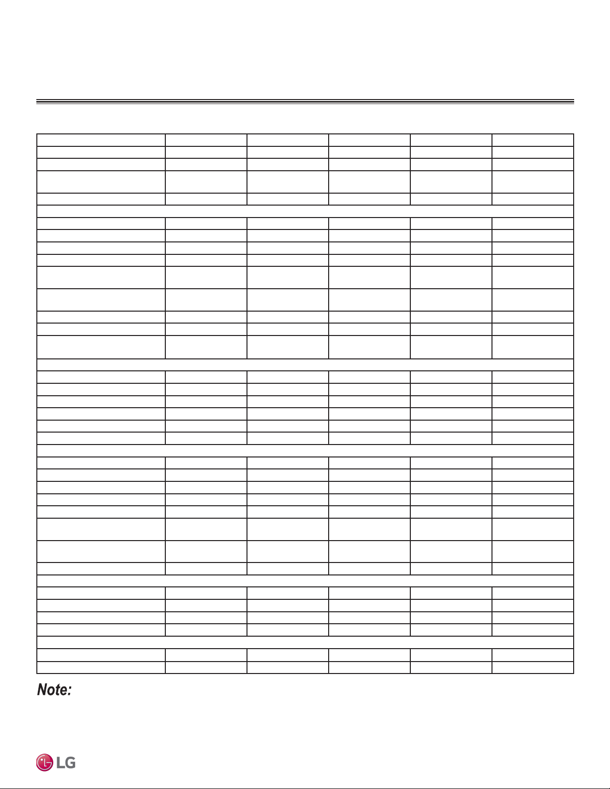
Base Rooftop DOAS
Table 2: Base Rooftop DOAS.
Model No.
Design Airflow (CFM) 2900 3200 3700 4600 5100
ESP (in. wg) 3 3 3 3 3
Entering Air Summer
DB / WB (°F)
Entering Air Winter
DB (°F)
Cooling Performance
Coil LAT DB / WB (°F) 54.8/54.6 54.7/54.5 54.3/54.2 54.6/54.4 54.6/54.3
Unit LAT DB / WB (°F) 84.7 83.4 82.3 82.3 81.9
Total Cooling
Capacity (MBH)
Sensible Cooling
Capacity (MBH)
Hot Gas Reheat Coil
Capacity (MBH)
Evaporator Coil
Depth(Rows)
No. of Compressors 2 2 2 2 2
Compressor Type(s)
Heating
Fuel Natural Gas Natural Gas Natural Gas Natural Gas Natural Gas
Capacity Input (MBH) 300 400 400 500 500
Capacity Output (MBH) 240 320 320 400 400
LAT (°F) 76.6 92.6 80.1 80.5 72.6
Turndown Type Modulating Modulating Modulating Modulating Modulating
Turndown Ratio 4:1 4:1 4:1 4:1 4:1
Supply Fan Data
Fan Quantity 1 1 1 1 1
Wheel Diameter (in.) 20 20 20 20 22
Wheel Speed (RPM) 1591 1622 1702 1671 1777
Motor HP 3 3 3 5 5
Configuration
Outdoor Air Intake End End End End End
Supply Air Discharge Bottom Bottom Bottom Bottom Bottom
Weight (lbs.) 3412 3487 3633 3697 3796
Rooftop Dedicated Outdoor Air System Installation Manual
Filtration
Hood None None None None None
Supply 2" MERV 8 2" MERV 8 2" MERV 8 2" MERV 8 2" MERV 8
AR-DR22-15A AR-DR22-17A AR-DR22-20A AR-DR22-25A AR-DR22-30A
95/75 95/75 95/75 95/75 95/75
0 0 0 0 0
202.2 223.8 262.2 323.1 359.6
128.4 141.8 165.7 204.5 227
93.6 99.1 111. 9 137.6 150.8
5 5 6 6 6
Digital scroll /
Standard scroll
Digital scroll /
Standard scroll
Digital scroll /
Standard scroll
Digital scroll /
Standard scroll
Digital scroll /
Standard scroll
• Capacity data above will change if entering air temperatures, leaving air temperatures (LAT), or airflow rates are varied.
• Take appropriate actions at the end of HVAC equipment life to recover, recycle, reclaim or destroy R410A refrigerant according to applicable
regulations (40 CFR Part 82, Subpart F) under section 608 of CAA.
10
Due to our policy of continuous product innovation, some specifications may change without notification.
©LG Electronics U.S.A., Inc., Englewood Cliffs, NJ. All rights reserved. “LG” is a registered trademark of LG Corp.
GENERAL DATA
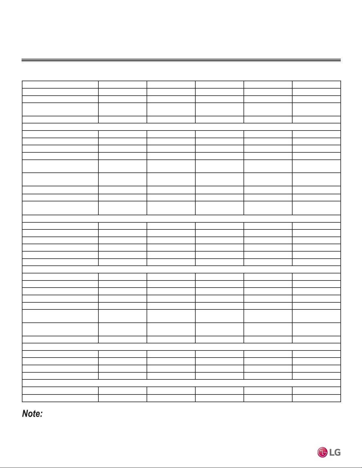
Energy Recovery Wheel Rooftop DOAS
Table 3: Energy Recovery Wheel Rooftop DOAS.
Model No.
Design Airflow (CFM) 1700 2600 2950 3700 4150
ESP (in. wg) 2 2 2 2 2
Entering Air Summer DB / WB
(°F)
Entering Air Winter DB (°F) 0 0 0 0 0
Cooling Performance
Coil EAT DB / WB (°F) 81.4/67.1 81.6/67.3 82.2/67.6 82.3/67.7 83/68.1
Coil LAT DB / WB (°F) 54.8/54.4 54.7/54.3 54.6/53.8 54.7/54.4 53.1/52.7
Unit LAT DB / WB (°F) 79.9 78.3 74.7 74.5 73.3
Total Cooling Capacity (MBH) 67 104 126.6 153.1 196.5
Sensible Cooling Capacity
(MBH)
Hot Gas Reheat Coil Capacity
(MBH)
Evaporator Coil Depth (Rows) 4 5 4 6 6
Number of Compressors 1 1 2 2 2
Compressor Type(s) Digital scroll Digital scroll
Heating
Fuel Natural Gas Natural Gas Natural Gas Natural Gas Natural Gas
Capacity Input (MBH) 100 100 150 200 200
Capacity Output (MBH) 80 80 120 160 160
LAT (°F) 92.9 76.9 83.7 85.7 78.9
Turndown Type Modulating Modulating Modulating Modulating Modulating
Turndown Ratio 4:1 4:1 4:1 4:1 4:1
Fan Data
Supply Fan Quantity 1 1 1 1 1
Supply Fan Wheel Diameter (in.) 14 18 14 18 18
Supply Fan Wheel Speed (RPM) 2316 1951 3089 2299 2462
Supply Fan Motor HP 1 3 5 5 7.5
Exhaust Fan Quantity 1 1 1 1 1
Exhaust Fan Wheel Diameter
(in.)
Exhaust Fan Wheel Speed
(RPM)
Exhaust Fan Motor HP 1 3 3 5 7.5
Configuration
Outdoor Air Intake End End End End End
Supply Air Discharge Bottom Bottom Bottom Bottom Bottom
Return Air Opening Bottom Bottom Bottom Bottom Bottom
Weight (lbs.) 2997 3213 3239 3414 3557
Filtration
Hood none none none none none
Supply 2" MERV8 2" MERV8 2" MERV8 2" MERV8 2" MERV8
AR-DE12-05A AR-DE12-07A AR-DE12-10A AR-DE12-12A AR-DE12-15A
95/75 95/75 95/75 95/75 95/75
49.6 76.7 89.6 112.1 136.3
46.1 66.1 64.1 79.2 90.7
Digital scroll /
standard scroll
14 18 18 18 18
2302 1725 1725 1750 1750
Digital scroll /
standard scroll
Digital scroll /
standard scroll
Product Data
• Capacity data above will change if entering air temperatures, leaving air temperatures (LAT), or airflow rates are varied.
• Take appropriate actions at the end of HVAC equipment life to recover, recycle, reclaim or destroy R410A refrigerant according to applicable
regulations (40 CFR Part 82, Subpart F) under section 608 of CAA.
Due to our policy of continuous product innovation, some specifications may change without notification.
©LG Electronics U.S.A., Inc., Englewood Cliffs, NJ. All rights reserved. “LG” is a registered trademark of LG Corp.
11
GENERAL DATA
Energy Recovery Wheel Rooftop DOAS
Table 4: Energy Recovery Wheel Rooftop DOAS.
Model No. AR-DE22-15A AR-DE22-17A AR-DE22-20A AR-DE22-25A AR-DE22-30A
Design Airflow (CFM) 5000 5510 6300 6750 7450
ESP (in. wg) 2 2 2 2 2
Entering Air Summer DB / WB
(°F)
Entering Air Winter DB (°F) 0 0 0 0 0
Cooling Performance
Coil EAT DB / WB (°F) 81.1/67 81.5/67.2 82.8/67.6 81.6/67.3 82.2/67.6
Coil LAT DB / WB (°F) 54.5/54.1 54.8/54.3 54.7/54.4 52.5/52.2 52.8/52.4
Unit LAT DB / WB (°F) 77.4 75.5 74.9 74.8 74.9
Total Cooling Capacity (MBH) 198.6 220.4 259.7 310.2 346.4
Sensible Cooling Capacity
(MBH)
Hot Gas Reheat Coil Capacity
(MBH)
Evaporator Coil Depth (Rows) 5 5 6 6 6
Number of Compressors 2 2 2 2 2
Compressor Type(s)
Heating
Fuel Natural Gas Natural Gas Natural Gas Natural Gas Natural Gas
Capacity Input (MBH) 300 300 300 300 300
Capacity Output (MBH) 240 240 240 240 240
LAT (°F) 94.6 88.9 81.3 81.1 76.1
Turndown Type Modulating Modulating Modulating Modulating Modulating
Turndown Ratio 4:1 4:1 4:1 4:1 4:1
Fan Data
Supply Fan Quantity 1 1 1 1 1
Supply Fan Wheel Diameter (in.) 20 20 20 20 22
Supply Fan Wheel Speed (RPM) 1986 2106 2305 2364 2049
Supply Fan Motor HP 7.5 7.5 10 10 10
Exhaust Fan Quantity 1 1 1 1 1
Exhaust Fan Wheel Diameter
(in.)
Exhaust Fan Wheel Speed
(RPM)
Exhaust Fan Motor HP 5 7.5 7.5 10 10
Rooftop Dedicated Outdoor Air System Installation Manual
Configuration
Outdoor Air Intake End End End End End
Supply Air Discharge Bottom Bottom Bottom Bottom Bottom
Return Air Opening Bottom Bottom Bottom Bottom Bottom
Weight (lbs.) 4624 4731 4901 5028 5084
Filtration
Hood none none none none none
Supply 2" MERV8 2" MERV8 2" MERV8 2" MERV8 2" MERV8
95/75 95/75 95/75 95/75 95/75
146.1 161.8 190.2 216 240.4
123.8 123 137.5 162.8 178.3
Digital scroll /
standard scroll
20 20 20 20 22
1750 1750 1750 1765 1765
Digital scroll /
standard scroll
Digital scroll /
standard scroll
Digital scroll /
standard scroll
Digital scroll /
standard scroll
• Capacity data above will change if entering air temperatures, leaving air temperatures (LAT), or airflow rates are varied.
• Take appropriate actions at the end of HVAC equipment life to recover, recycle, reclaim or destroy R410A refrigerant according to applicable
regulations (40 CFR Part 82, Subpart F) under section 608 of CAA.
12
Due to our policy of continuous product innovation, some specifications may change without notification.
©LG Electronics U.S.A., Inc., Englewood Cliffs, NJ. All rights reserved. “LG” is a registered trademark of LG Corp.
REFRIGERANT SAFETY
WARNING
WARNING
Installation, startup, and service must be performed by a qualied installer, service agency, or gas supplier.
Improper installation, adjustment, service, maintenance, or alteration can cause personal injury or loss of life.
Installation, startup, and service must be performed by a qualied installer, service agency, or gas supplier.
Improper installation, adjustment, service, maintenance, or alteration can cause property damage.
The customer must provide proper equipment and fully trained installers to follow local safety requirements when receiving, installing, or
servicing equipment. Consult all local building, electrical, occupational safety, and gas codes.
Lock out all power supplies before servicing the unit to prevent accidental startup. All fan blades should be secured to prevent wind rotation.
Remove any restrictive device before restoring power.
The Clean Air Act of 1990 bans the intentional venting of refrigerant (CFC and HCFC) as of July 1, 1992. Approved methods of recovery,
recycling, or reclaiming refrigerant must be followed. Fines and / or incarceration may be levied for non-compliance.
ASHRAE Standards 15-2101 and 34-2010 offer guidelines that address refrigerant safety and the maximum allowable concentration of
refrigerant in an occupied space. Refrigerant will dissipate into the atmosphere, but a certain volume of air is required for this to occur safely.
For R410A refrigerant, the maximum allowable concentration of refrigerant is twenty-six (26) lbs. per 1,000 cubic feet of an occupied space.
Institutional buildings allow half of that concentration.
Product Data
ASHRAE Standards 15 and 34 assume that if a system develops a leak, its entire refrigerant charge will dump into the area where the leak
occurs. To meet ASHRAE Standards 15 and 34, calculate the refrigerant concentration that may occur in the smallest room volume on the
system, and compare the results to the maximum allowable concentration number. Also, consult state and local codes in regards to refrigerant safety.
Verify the maximum refrigerant concentration level for spaces served by DOAS meets the concentration limit for the application.
Due to our policy of continuous product innovation, some specifications may change without notification.
©LG Electronics U.S.A., Inc., Englewood Cliffs, NJ. All rights reserved. “LG” is a registered trademark of LG Corp.
13
RECEIVING GUIDELINES
Receiving Guidelines
This product may have been subject to road salt during transit. If so, immediately wash off all visible white residue from all exterior surfaces.
Upon receiving the product, check to ensure all line items are accounted for by referencing the delivery receipt or packing list.
Inspect each crate or carton for shipping damage before accepting delivery.
Alert the carrier if any damage is detected, do not refuse shipment.
The customer shall make notation of damage (or shortage of items) on the delivery receipt and all copies of the bill of lading which should be
countersigned by the delivering carrier. If damaged, immediately contact your manufacturer’s representative. Any physical damage to the unit
after acceptance is not the responsibility of the manufacturer.
Handling Guidelines
Units are to be rigged and moved by the lifting brackets provided or by the skid when a forklift is used. Location of brackets varies by model
and size.
Handle in such a manner as to keep from scratching or chipping the coating. Damaged finish may reduce ability of unit to resist corrosion.
Unpacking Guidelines
Verify that all required parts and the correct quantity of each item have been received. If any items are missing, report shortages to your
local representative to arrange for obtaining missing parts. Sometimes it is not possible that all items for the unit be shipped together due to
availability of transportation and truck space.
Confirmation of shipment(s) must be limited to only items on the bill of lading.
Check control cabinet for eld mounted sensors shipped loose.
Storage Guidelines
Units are protected against damage during shipment. If the unit cannot be installed and operated immediately, precautions need to be taken
to prevent deterioration of the unit during storage. The user assumes responsibility of the unit and accessories while in storage. The manufacturer will not be responsible for damage during storage. These suggestions are provided solely as a convenience to the user.
The ideal environment for the storage of units and accessories is indoors, above grade, in a low humidity atmosphere which is sealed to prevent the entry of blowing dust, rain, or snow. Units designed for outdoor applications may be stored outdoors. All accessories must be stored
indoors in a clean, dry atmosphere.
Indoor Maintenance Guidelines
Maintain temperatures evenly to prevent condensation. Remove any accumulations of dirt, water, ice, or snow and wipe dry before moving
to indoor storage. To avoid condensation, allow cold parts to reach room temperature. Leave coverings loose to permit air circulation and to
allow for periodic inspection.
Rooftop Dedicated Outdoor Air System Installation Manual
The unit should be stored at least 3½ in. (89 mm) off the floor. Clearance should be provided to permit air circulation and space for inspection.
Outdoor Placement Guidelines
The unit should be placed on a level surface to prevent water from leaking into the unit. The unit should be elevated so that it is above water
and snow levels.
Ensure sufficient support to prevent unit from settling into soft ground. Locate parts far enough apart to permit air circulation, sunlight, and
space for periodic inspection. To minimize water accumulation, place all unit parts on blocking supports so that rain water will run off.
Do not cover parts with plastic film or tarps as these cause condensation of moisture from the air passing through heating and cooling
cycles.
14
Due to our policy of continuous product innovation, some specifications may change without notification.
©LG Electronics U.S.A., Inc., Englewood Cliffs, NJ. All rights reserved. “LG” is a registered trademark of LG Corp.
WARNING
INSPECTION AND MAINTENANCE
Inspection and Maintenance
While in storage, inspect units once per month. Keep a record of inspection and maintenance performed.
If moisture or dirt accumulations are found on parts, the source should be located and eliminated. At each inspection, rotate the fan wheel
by hand ten to fifteen revolutions to distribute lubricant on motor. If paint deterioration begins, consideration should be given to touch-up or
repainting. Units with special coatings may require special techniques for touch-up or repair.
Machined parts coated with rust preventive should be restored to good condition promptly if signs of rust occur. Immediately remove the
original rust preventive coating with petroleum solvent and clean with lint-free cloths. Polish any remaining rust from surface with crocus cloth
or fine emery paper and oil.
Do not destroy the continuity of the surfaces. Wipe thoroughly clean with Tectyl® 506 (Ashland Inc.) or the equivalent. For hard to reach
internal surfaces or for occasional use, consider using Tectyl® 511M Rust Preventive, WD-40® or the equivalent.
Removing from Storage
As units are removed from storage to be installed in their final location, they should be protected and maintained in a similar fashion until the
equipment goes into operation.
Prior to installing the unit and system components, inspect the unit assembly to make sure it is in working order.
1. Check all fasteners, set screws on the fan, wheel, bearings, drive, motor base, and accessories for tightness.
2. Rotate the fan wheel(s) by hand and assure no parts are rubbing.
Installation
• Failure to follow proper instructions could result in serious injury or death.
• Use the appropriate crane equipment to transport each unit; ensure the crane is capable of supporting the weights listed in the specification
tables. If the crane is not properly secured, it may result in an accident that causes physical injury or death.
• Never lift the units in windy conditions.
• Wear protective gloves when handling equipment. Sharp edges may cause personal injury.
• Tear apart and throw away plastic packaging so that children may not play with them and risk suffocation and death.
Failure to follow proper instructions could result in property damage.
Due to our policy of continuous product innovation, some specifications may change without notification.
©LG Electronics U.S.A., Inc., Englewood Cliffs, NJ. All rights reserved. “LG” is a registered trademark of LG Corp.
15
INSPECTION AND MAINTENANCE
This is a horizontally configured High Percentage Outdoor Air unit designed for installation either indoors or outdoors. Each unit has multiple
options for cooling and/or heating. The unit is designed to replace air that is exhausted from the building and also heat and cool, as needed.
The air volume produced by the unit is constant, but can be optionally modulated to provide a variable air volume (VAV) and recirculation is
also offered as an option.
Cooling Options
Units have the following cooling options available:
• Packaged DX
• Split DX (thermal expansion valve is field-provided)
• Chilled water coil
Units with packaged DX are shipped fully charged with refrigerant and are ready for operation upon arrival.
Heating Options
There are three different optional heat sources that can be ordered for this unit:
• Indirect gas-fired furnace with one or two sets of heat exchangers
• Electric heat with infinitely variable SCR control
• Hot water coil
Airow Arrangement
The unit is capable of Constant Air Volume (CAV), Variable Air Volume (VAV), 100% Outdoor Air and have recirculating air options.
Safety Listing
Models are listed per ANSI/UL 1995, Heating and Cooling Equipment and are ETL Certified.
Models and Capacities
Table 5: Energy Recovery Wheel Rooftop DOAS.
Model Cooling Capacity
AR-DR12-XX 5 to 15 tons
AR-DR22-XX 15 to 30 tons
AR-DE12-XX 5 to 15 tons
AR-DE22-XX 15 to 30 tons
Rooftop Dedicated Outdoor Air System Installation Manual
16
Due to our policy of continuous product innovation, some specifications may change without notification.
©LG Electronics U.S.A., Inc., Englewood Cliffs, NJ. All rights reserved. “LG” is a registered trademark of LG Corp.
SUBASSEMBLIES
Blower
Either one or two plenum-type fans. All units are equipped with a plenum fan for Supply Air and a second may be selected for Exhaust (Relief) Air.
Coils
• Evaporator coil (optional)
• Condenser coil (optional, packaged DX only)
• Water coil (optional)
• Reheat coil (optional)
Compressors
Each unit having packaged DX will have one or two refrigerant compressors. One of the compressors will be a digital scroll type compressor.
Dampers
Motorized intake air damper, motorized recirculating damper. Optional return air damper. Optional gravity-type exhaust damper.
Optional Barometric Relief Damper
Used during economizer mode of the unit when building pressure increases, relief damper will open due to over pressurization.
Electric Heater
An SCR controlled electric heater is available on the units. It requires a separate power supply and has its own control panel. See unit-
specific wiring diagram.
Installation
Filters
2-inch thick metal mesh filters in the outdoor weatherhood intake, 2-inch thick pleated paper MERV 8 (standard) or MERV 13 filters in the
air stream. Optional 4-inch thick filter bank with a 2-inch thick MERV 8 and 2-inch thick MERV 13 or a 4-inch thick MERV 14 pleated paper
supply filters.
Indirect Gas-Fired Furnace
Furnace model PVG is available on AR-DR12, AR-DE12, AR-DR22, and AR-DE22.
Packaged DX System
Any unit may be ordered with a packaged DX system. Housing size 112 will include either one or two compressors; housing size
212 will include two compressors; a condenser coil(s) and evaporator coil(s) and all required components. Units that have packaged DX are
charged with R410A refrigerant. Do not use tools or parts designed for other refrigerants on these units.
Vestibule
Some units may be ordered with a factory- assembled vestibule that is to be field-attached to the side of the unit. See lifting instructions.
Due to our policy of continuous product innovation, some specifications may change without notification.
©LG Electronics U.S.A., Inc., Englewood Cliffs, NJ. All rights reserved. “LG” is a registered trademark of LG Corp.
17
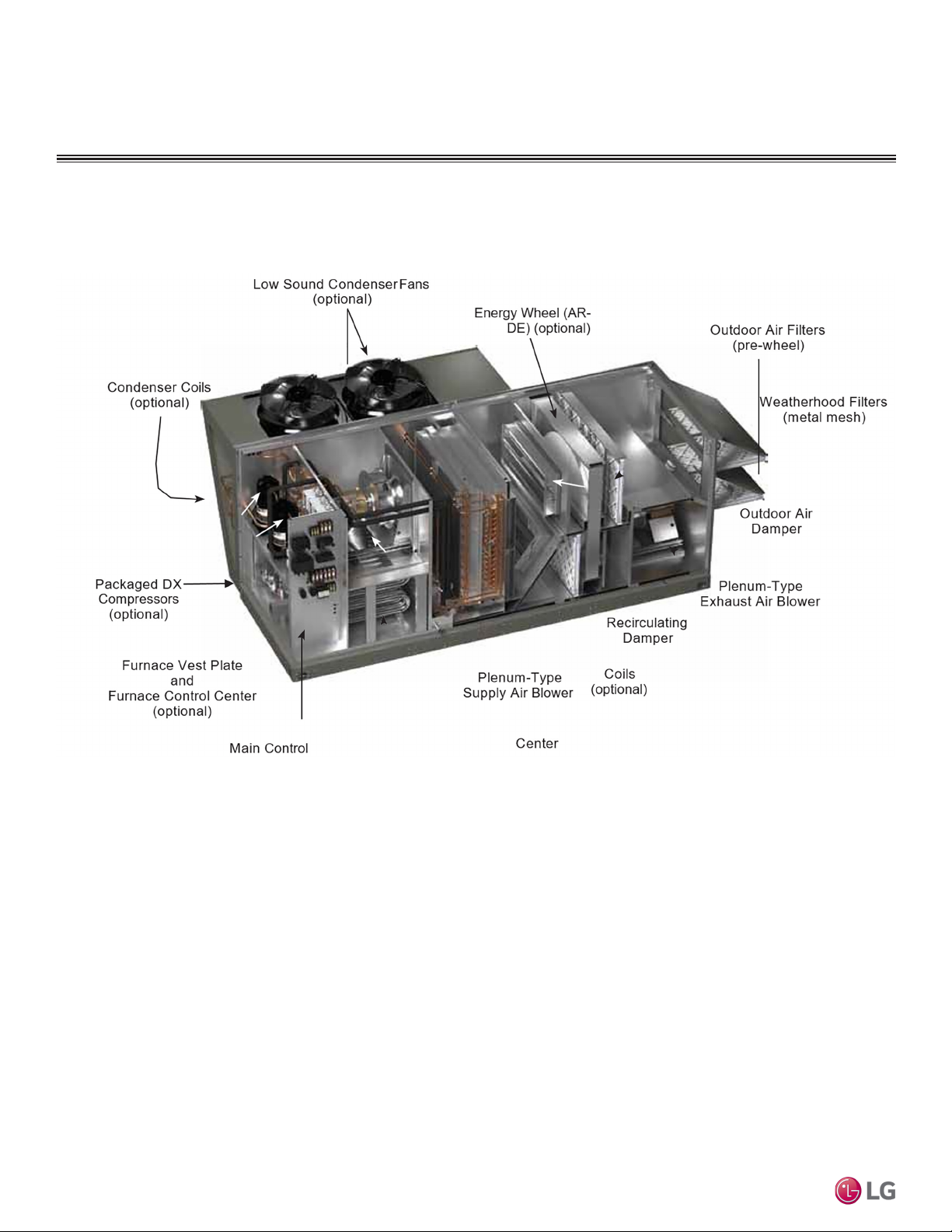
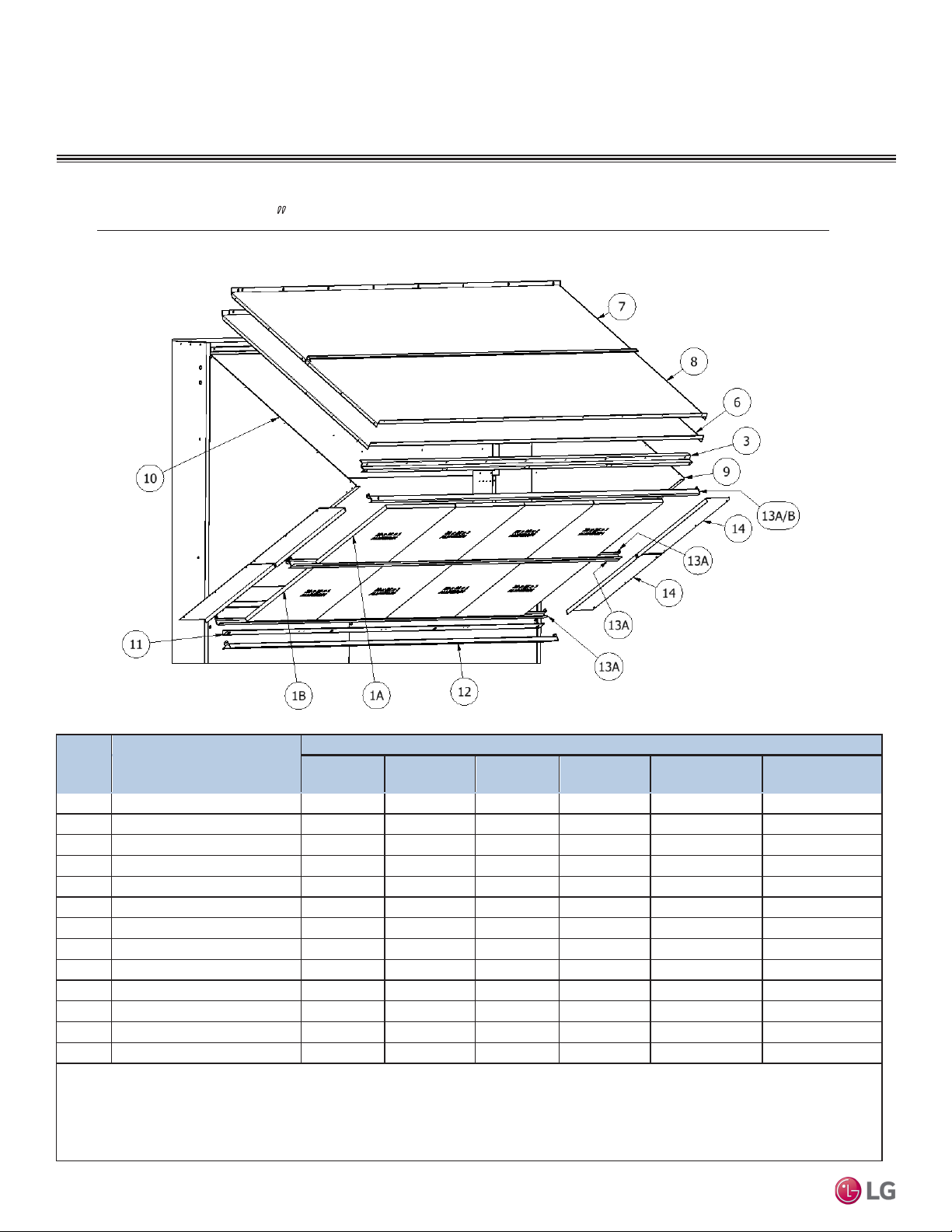
SUBASSEMBLIES
Open view of Model AR-DE showing optional condenser coil, fans and
energy recovery wheel.
Figure 1: DOAS AR-DE Model Open View
Rooftop Dedicated Outdoor Air System Installation Manual
18
Due to our policy of continuous product innovation, some specifications may change without notification.
©LG Electronics U.S.A., Inc., Englewood Cliffs, NJ. All rights reserved. “LG” is a registered trademark of LG Corp.
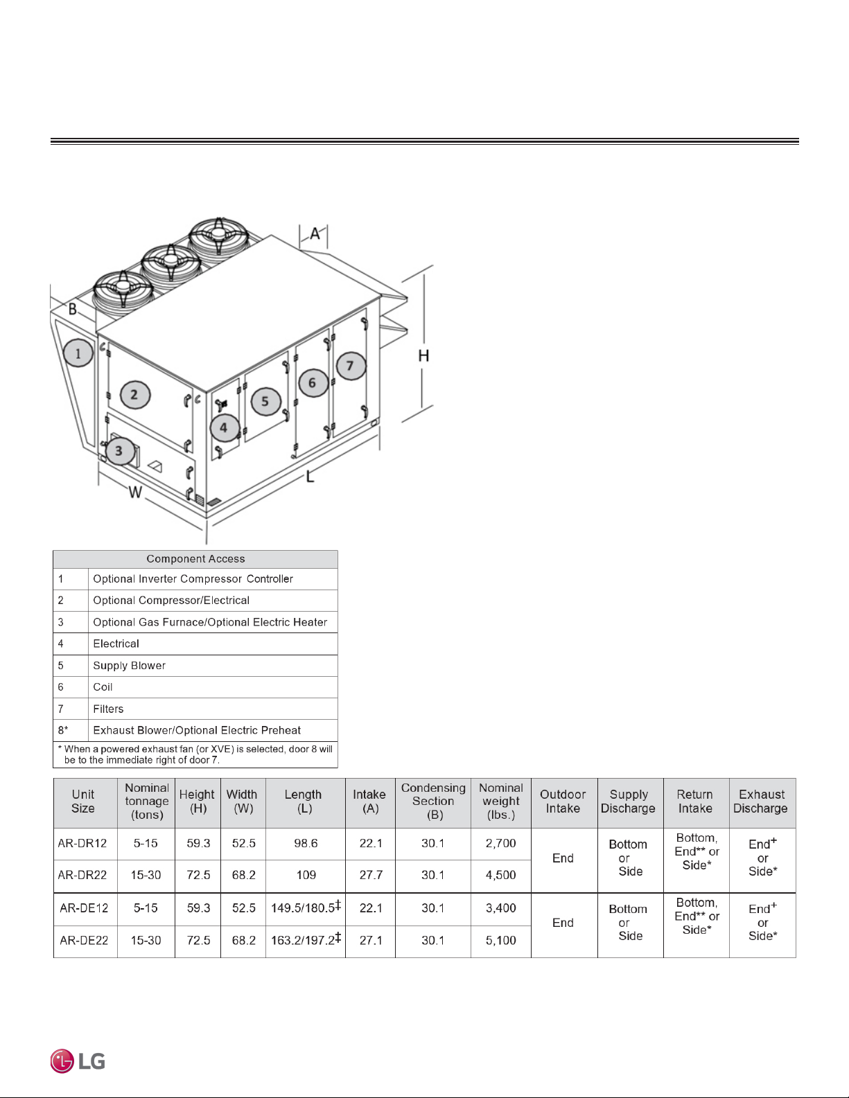
Typical Unit Weights and Dimensions
Figure 2: DOAS AR-DE Model
INSTALLATION
Installation
All dimensions are shown in inches. Weight is shown in pounds and includes largest supply and exhaust fans, PDX with reheat, largest indi-
rect-gas fired furnace, and all dampers. Actual weights will vary based on the unit configuration.
* Only available with powered exhaust. **Only available without barometric relief.
+Only available with barometric relief. ‡ Length with side return.
Due to our policy of continuous product innovation, some specifications may change without notification.
©LG Electronics U.S.A., Inc., Englewood Cliffs, NJ. All rights reserved. “LG” is a registered trademark of LG Corp.
19
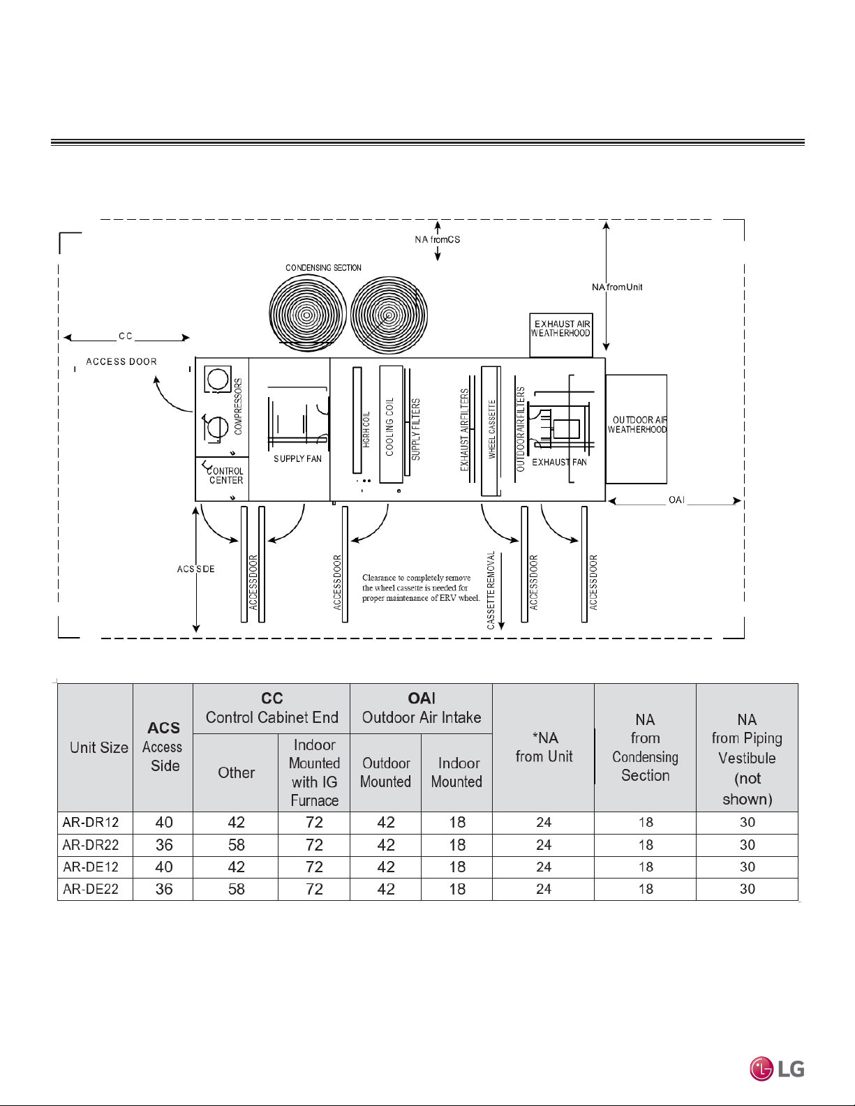
INSTALLATION
Service Clearnces
Figure 3: DOAS AR-DE Model
Rooftop Dedicated Outdoor Air System Installation Manual
All dimensions are shown in inches. *No condensing section or piping vestibule, or unit has top condensing section.
20
Due to our policy of continuous product innovation, some specifications may change without notification.
©LG Electronics U.S.A., Inc., Englewood Cliffs, NJ. All rights reserved. “LG” is a registered trademark of LG Corp.
INSTALLATION
WARNING
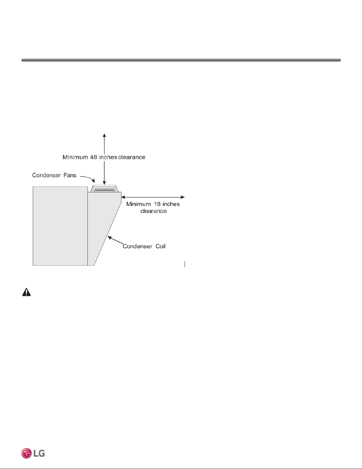
Additional Clearances for Packaged DX Units
Packaged DX units require additional clearance because they must have unrestricted air movement around the condenser coil and condenser fans. Hot air is being discharged from the condenser fans during operation. Enough clearance must be provided to avoid recirculation or
coil starvation. When equipped with condenser coils, the unit should never be placed under an overhang or inside a building. A minimum of
48 inches above the condenser fans is acceptable, but unobstructed is strongly recommended.
End view of rooftop unit with Packaged DX
Figure 4: DOAS Packaged DX Unit: End view of rooftop unit
Handling Concerns for Units with Packaged DX
Units having packaged DX have a system that is pressurized with refrigerant and if it is damaged, the refrigerant could leak
into the atmosphere or cause bodily harm due to the extreme cold nature of expanding refrigerant. Use protective equipment
such as gloves and safety glasses to minimize or prevent injury in case of a system leak during installation.
Exposure to high concentration levels of refrigerant gas may lead to illness or death.
Before Lifting - Vestibule
Determine whether or not the unit has a vestibule that must be field-attached to the side of the unit. Vestibules are shipped assembled but
detached from the unit.
They have lifting lugs on them so they can also be lifted by crane, but the installed location of the unit may make it preferable to install the
vestibule on the unit prior to lifting.
Before Lifting - Field Power Access
Determine where high voltage and low voltage wiring is to be brought into the cabinet. If wiring is to be brought into the cabinet through the
floor, see Alternate Supply Entry Locations in this manual. If unit is to be installed on a roof, cut access openings in the roof deck as needed.
Installation
Due to our policy of continuous product innovation, some specifications may change without notification.
©LG Electronics U.S.A., Inc., Englewood Cliffs, NJ. All rights reserved. “LG” is a registered trademark of LG Corp.
21
INSTALLATION
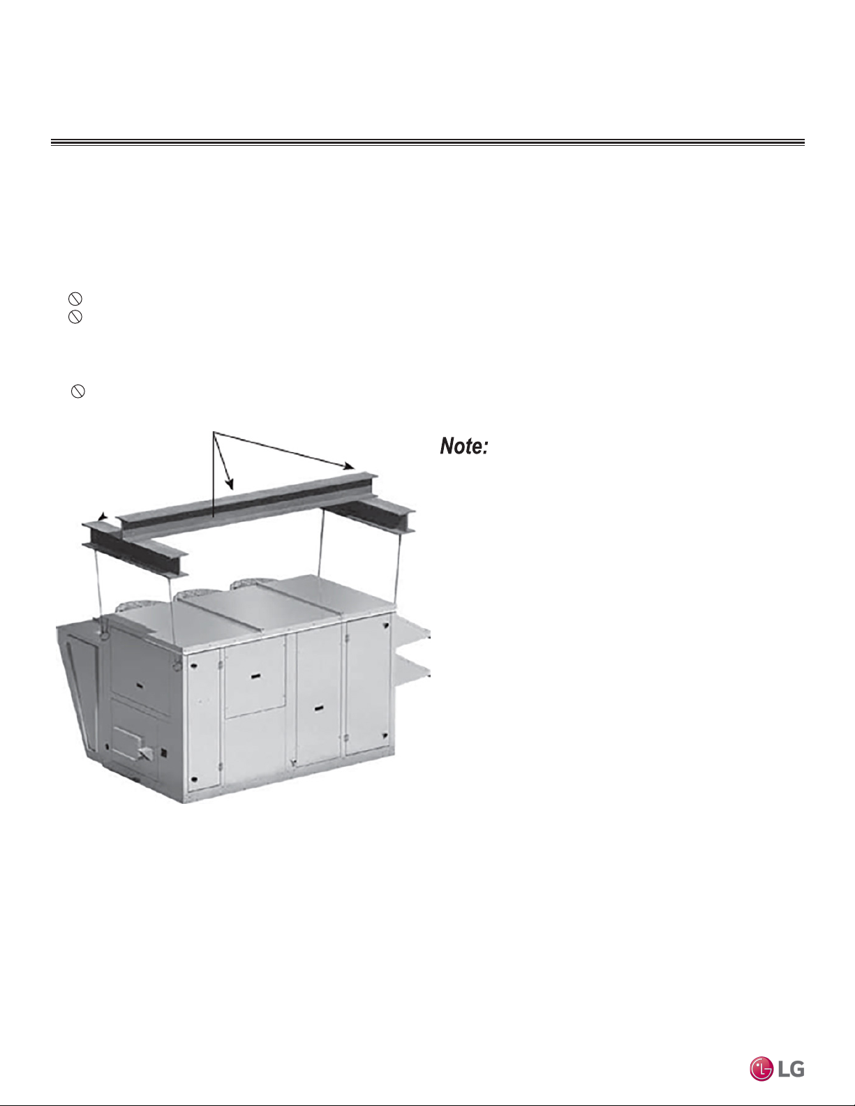
Lifting
1. Before lifting, ensure that all shipping materials have been removed from unit.
2. To assist in determining rigging requirements, weights are provided in the Unit Weights & Dimensions section of this manual.
3. Unit must be lifted by all lifting lugs provided at top of unit.
4. Spreader bars must span the unit to prevent damage to the cabinet by the lift cables.
5. Always test-lift the unit to check for proper balance and rigging before hoisting to desired location.
6. Never lift unit by weatherhood.
7. Never lift units in windy conditions.
8. Preparation of curb and roof openings should be completed prior to lifting unit to the roof.
9. Check to be sure that gasketing (supplied by others) has been applied to the top of the curb prior to lifting the unit and setting on the
curb.
10. Do not use fork lifts for handling unit.
Figure 5: DOAS Unit: Spreader Bar.
Spreader bars are required to prevent damage to the cabinet. Failure
to follow proper instructions could result in property damage.
Rooftop Dedicated Outdoor Air System Installation Manual
22
Due to our policy of continuous product innovation, some specifications may change without notification.
©LG Electronics U.S.A., Inc., Englewood Cliffs, NJ. All rights reserved. “LG” is a registered trademark of LG Corp.
INSTALLATION
Roof Curb Mounting
Roof curb details, including duct locations and dimensions, are to be found in the
roof curb assembly instructions.
Rooftop units require curbs to be mounted first. The duct connections must be located so they will be clear of structural members of the building.
Factory-Supplied Roof Curbs
Roof curbs are model GKD which are shipped in a knockdown kit (includes duct
adapters) and require field assembly (by others). Assembly instructions are included
with the curb kit.
Install Curb
Locate curb over roof opening and fasten in place. Check that the diagonal dimensions are within ± 1/8 inch of each other and adjust as necessary. For proper
coil drainage and unit operation, it is important that the installation be level. Shim
the curb as required to level. Install gasketing on top surface of curb (provided by
others).
Install Ductwork
Installation of all ducts should be done in accordance with SMACNA and AMCA
guidelines. Duct adapters are provided to support ducts prior to setting the unit.
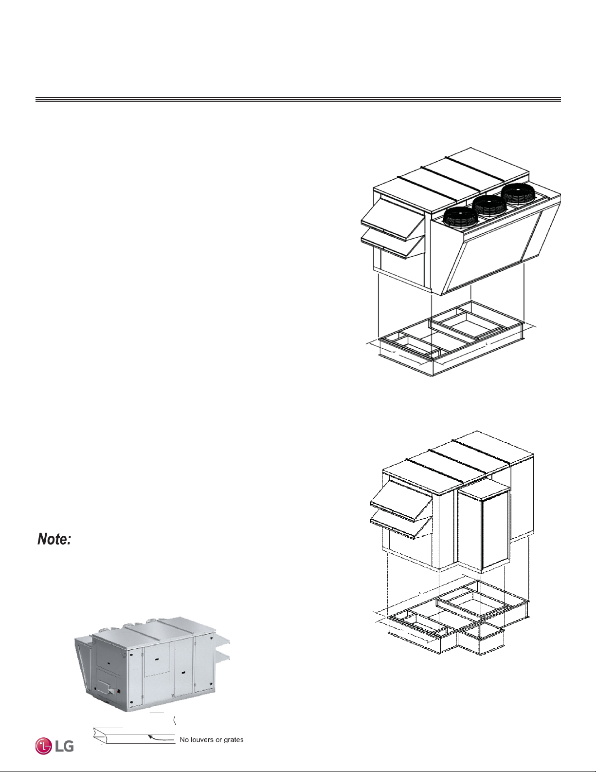
Set the Unit
Lift unit to a point directly above the curb and duct openings. Guide unit while lower-
ing to align with duct openings. Roof curbs fit inside the unit base. Make sure the unit
is properly seated on the curb and level.
Install Vestibule
If unit was ordered with a vestibule and it has not yet been attached to the unit, caulk
and attach the vestibule at this time.
Figure 6: Typical Unit with Condensing Section and
Factory Supplied Curb Kit.
Installation
Figure 7: Typical Unit with Piping Vestibule and
Factory Supplied Curb Kit.
Optional Piping Vestibule
If the unit was ordered with the vestibule, the NA (Non- Access side) clearance
dimension must be measured from the vestibule.
Ductwork Configurations
Downblast Discharge Ductwork - whenever downblast discharge is used, the
ductwork directly beneath the unit must be connected with either a “T” or an “L” con-
guration and the area directly beneath the heat source must not have any openings
such as louvers or grates.
Figure 8: Downblast Discharge Ductwork
Due to our policy of continuous product innovation, some specifications may change without notification.
©LG Electronics U.S.A., Inc., Englewood Cliffs, NJ. All rights reserved. “LG” is a registered trademark of LG Corp.
23
INSTALLATION
WARNING
Rail Mounting and Layout
1. The units may be installed on rails provided and installed by others.
Ensure that rails are designed to handle the weight of the unit and
provide proper load distribution on building supports.
2. Make sure that rail positioning does not interfere with the openings
on the unit.
3. Rails should run the width of the unit and extend beyond the unit a
minimum of 12 inches on each side.
4. Set unit on rails.
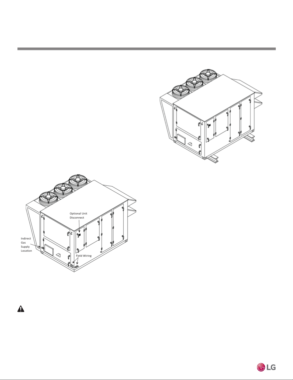
Recommended Electrical and Gas
Supply Entry Locations
Manufacturer recommends that electrical service and gas supply be
brought into the cabinet through the end wall, as shown below. There
are three penetrations into the cabinet that are required; one for high
voltage supply wiring, one for low voltage control wiring, and one for
either gas supply or high voltage supply wiring for an electric heater.
Figure 10:
Recommended Gas and Electric Supply Entry Locations
Figure 9: Typical Unit Installed on Field Supplied Rails
Rooftop Dedicated Outdoor Air System Installation Manual
Alternate Supply Entry Locations
Each installation is unique and as a result, alternate entry locations may be field-located. Before using
any alternate entry location, verify the suitability of the location and ensure the use of an alternate location does not interfere with unit wiring, components or functionality.
Never drill holes in the roof of the unit! There is high voltage wiring located between the inner and outer roof
panels. Damage to the wiring could cause severe bodily harm or death.
24
Due to our policy of continuous product innovation, some specifications may change without notification.
©LG Electronics U.S.A., Inc., Englewood Cliffs, NJ. All rights reserved. “LG” is a registered trademark of LG Corp.
OUTDOOR AIR HOOD ASSEMBLY
WARNING
Improper installation, adjustment, service, maintenance, or alteration can cause personal injury, or loss of life.
Installation, startup, and service must be performed by a qualied installer, service agency, or gas supplier.
Improper installation, adjustment, service, maintenance, or alteration can cause property damage.
Installation, startup, and service must be performed by a qualied installer, service agency, or gas supplier.
The customer must provide proper equipment and fully-trained installers to follow local safety requirements when receiving, installing, or
servicing equipment. Consult all local building, electrical, occupational safety, and gas codes.
Lock out all power supplies before servicing the unit to prevent accidental startup. All fan blades should be secured to prevent wind rotation.
Remove any restrictive device before restoring power.
The Clean Air Act of 1990 bans the intentional venting of refrigerant (CFC and HCFC) as of July 1, 1992. Approved methods of recovery,
recycling, or reclaiming refrigerant must be followed. Fines and/or incarceration may be levied for non-compliance.
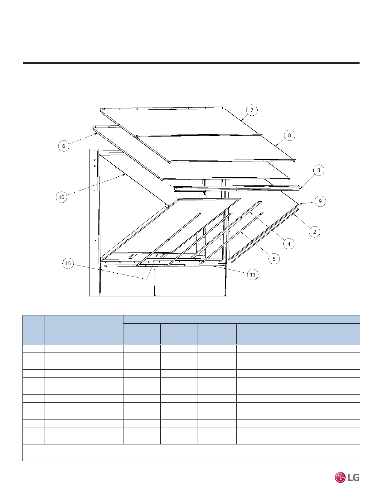
Outdoor Air Intake Hood
Each VPR, VPRC/P, VPRE, and VPRX series ventilator comes with a factory-supplied outdoor air intake hood that must be assembled prior
to startup. The outdoor air intake hood is available in two options:
• Hood with optional 1” aluminum filters
• Standard hood with bird screen
The individual parts of the intake hood are located between the outdoor air intake damper and the intake hood top piece (item #6 for models
110/210/310; items #7 and #8 for models 350/352), which is secured flush with the end of the unit during shipment. The 1” aluminum filters
are located in the intake compartment behind the outdoor air intake damper. The outdoor air intake end of the unit is opposite access to
controls and compressors.
Tools Needed
• Power tool with 5/16”socket drive
• Phillips power bit # 2
• Sheet metal bending hand tool
Installation
Due to our policy of continuous product innovation, some specifications may change without notification.
©LG Electronics U.S.A., Inc., Englewood Cliffs, NJ. All rights reserved. “LG” is a registered trademark of LG Corp.
25
OUTDOOR AIR HOOD ASSEMBLY
Part Number (Quantity)
Description
350 Casing ALL
352 Casing
352 Casing
1A
ALUM FILTER-A
16x20x1 (2)
20x25x1 (2)
20x25x1 (2)
16x20x1 (8)
20x25x1 (8)
16x20x1 (8)
1B
ALUM FILTER-B
N/A
N/A
16x25x1 (1)
N/A
N/A
20x25x1 (4)
3
HOOD END
5656
2502 (1)
2507 (1)
2512 (1)
2038 (1)
4619 (1)
6
HOOD TOP-A
5712
2500 (1)
2505 (1)
2510 (1)
N/A
N/A
7
HOOD TOP-B
N/A
N/A
N/A
N/A
2032 (1)
4612 (1)
8
HOOD TOP-C
N/A
N/A
N/A
N/A
2037 (1)
4616 (1)
9
RIGHT SIDE TRIANGLE
5713
1317 (1)
4087 (1)
8087 (1)
2033 (1)
4613 (1)
10
LEFT SIDE TRIANGLE
5714
1318 (1)
4088 (1)
8088 (1)
2034 (1)
4614 (1)
11
BOTTOM FLASHING
5728
1229 (1)
4297 (1)
8297 (1)
2039 (1)
4617 (1)
12
ALUM FILTER BOTTOM
N/A
N/A
4431 (1)
N/A
2308 (1)
4865 (1)
13A
ALUM FILTER RAIL
5727
1352 (2)
4429 (2)
8424 (3)
2309 (4)
2309 (4)
13B
ALUM FILTER TOP RAIL
N/A
N/A
N/A
8436 (1)
N/A
N/A
14
ALUM FILTER SIDE SPACER
5726
1353 (2)
4430 (2)
8425 (4)
2310 (4)
2310 (2) & 4864 (4)
•
VPR-V10, VPR-110 & VPR-210 have only one row of aluminum filters.
The outdoor air hood on all VPRC/P units is located at the bottom of the unit.
Intake Hood with 1″ Aluminum Filters
Item #
V10 Casing 110 Casing 210 Casing 310 Casing
Rooftop Dedicated Outdoor Air System Installation Manual
•
VPR-352 and VPRX-352 have three rows of aluminum filters.
•
VPR-210, VPR-352, and VPRX-352 have two different filter sizes.
•
VPR-310 has a special aluminum filter rail top.
•
26
Due to our policy of continuous product innovation, some specifications may change without notification.
©LG Electronics U.S.A., Inc., Englewood Cliffs, NJ. All rights reserved. “LG” is a registered trademark of LG Corp.
VPR/VPRX
OA Hood Assembly
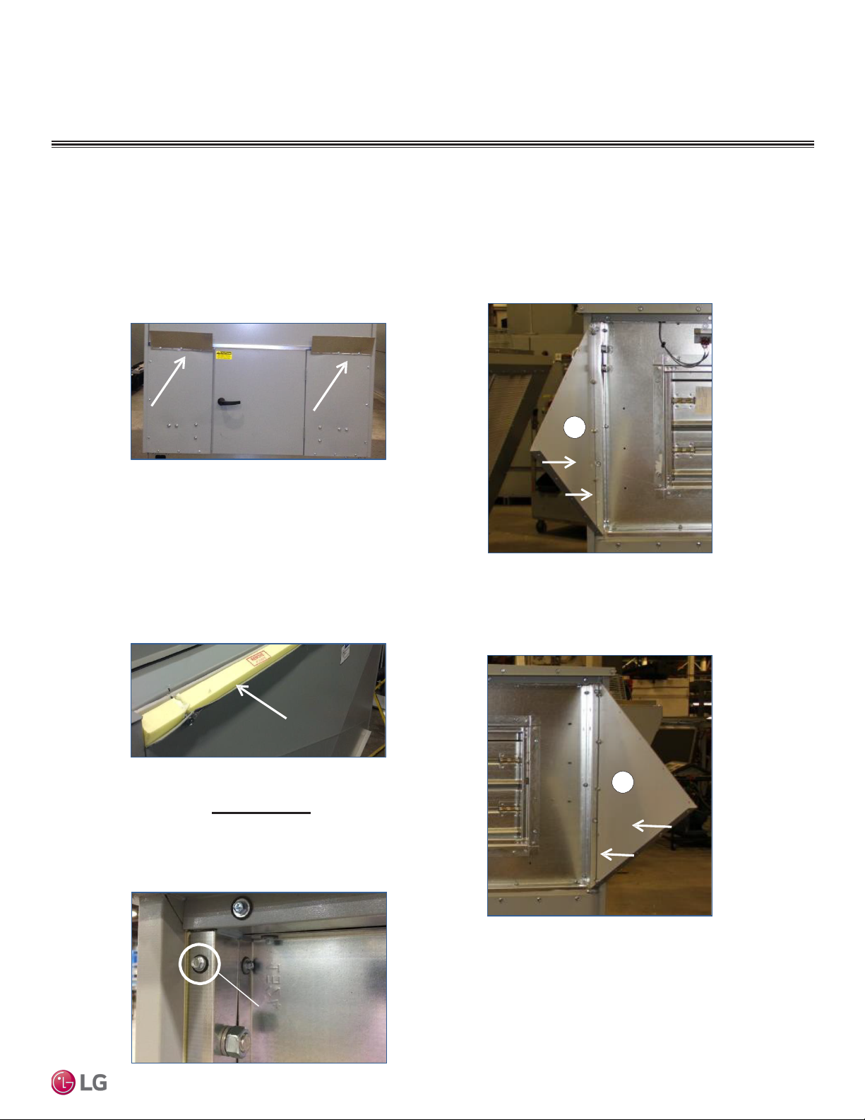
1.
Remove the shipping brackets used to
secure the intake hood in transit. The
brackets (shown below) are typically
fabricated of galvanized steel and may be
discarded. Retain the sheet-metal screws
for use in assembling the OA hood.
OUTDOOR AIR HOOD ASSEMBLY
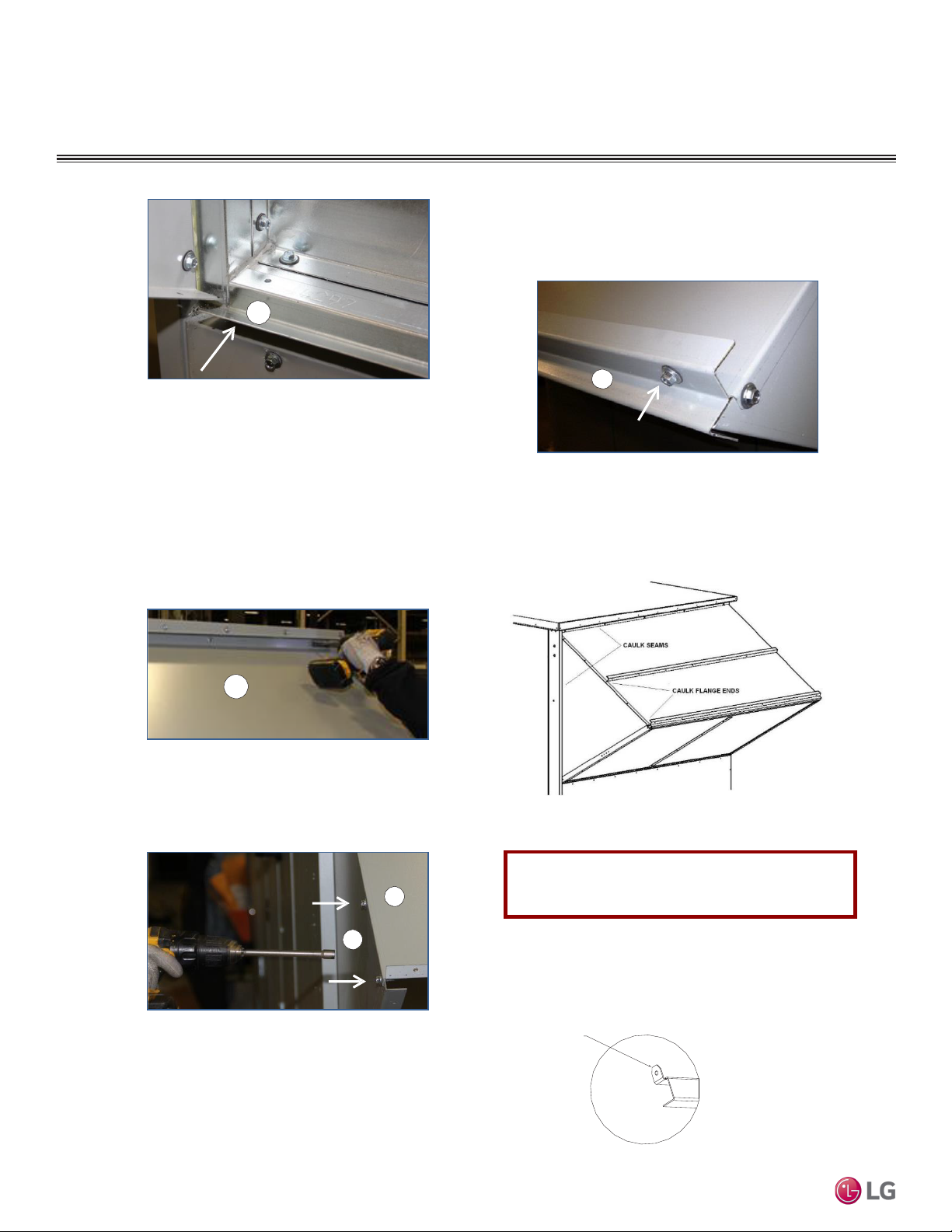
6.
Install the LEFT SIDE TRIANGLE support
(item #10) by aligning the pre-punched holes
with the dimples inside the outdoor air intake
sill. Fasten with 5/16″ hex-head screws. The
flanged side of the triangle should be on the
bottom of the hood and facing in to the
center of the unit, as shown below.
10
Step 1: Location of shipping brackets.
2.
Remove the row of screws holding the top of
the hood to the unit. Set aside the top of the
hood and the screws, which will be used in a
later step.
3.
Remove and discard the shipping foam or
tape. Do not remove the adhesive-backed
grey gaske
Step 3: Remove and discard shipping foam.
4.
Remove and take inventory of parts
t from the unit.
shipped in the sill of the opening.
5.
Remove the lug channel screw on each side
of the unit if not already removed.
Step 6: Install left support triangle with flange facing in.
7.
Install the RIGHT SIDE TRIANGLE support
(item #9) the same way, with the flange on
the bottom and facing in, as shown below.
9
Installation
Screw to remove
Step 5: Location of lug channel screws to remove.
Due to our policy of continuous product innovation, some specifications may change without notification.
©LG Electronics U.S.A., Inc., Englewood Cliffs, NJ. All rights reserved. “LG” is a registered trademark of LG Corp.
Step 7: Install right support triangle with flange facing in.
8.
Install the “S” rail bottom flashing (item #11)
on the bottom of the intake sill as shown
below. Align the pre-punched holes with the
dimples provided on the top edge of the sill.
Fasten with the provided 5/16″ hex-head
screws.
27
OUTDOOR AIR HOOD ASSEMBLY
11
Step 8: Install bottom flashing.
9.
Place the HOOD TOP (item #6) on top of
the triangular side supports, as shown in the
following figure. Fasten the top edge of the
hood to the unit using the 5/16″ x 1.5″
screws removed previously from the
shipping brackets.
CAUTION: Assistance is required to perform
this step for the larger hood on the
310/350/352 models.
11.
12.
Align the pre-punched holes in the HOOD
END piece (item #3) with the leading edge
of the hood top. Secure in place with the
provided 5/16″ hex-head screws.
3
Step 11: Install the hood end by lining up
the pre-punched holes.
Caulk the top and side seams where the
hood meets the unit and at the ends of the
flanges on both sides, as shown below.
6
Step 9: Install the hood top and fasten with screws.
10.
Attach the left and right edges of the top of
the hood to the triangular supports using the
provided 5/16″ hex-head screws.
Rooftop Dedicated Outdoor Air System Installation Manual
Step 10: Fasten the left and right triangles to the top.
10
Step 12: Caulk top and side seams.
For installation of bird screen, stop here and
6
proceed with assembly instructions on page 158.
13.
On items #12, #13A, and #13B, bend end
tabs 90 degrees with sheet metal bending
tool. Item #13B is on
ly shipped with the 310
casing.
BEND TAB
90°
28
Due to our policy of continuous product innovation, some specifications may change without notification.
©LG Electronics U.S.A., Inc., Englewood Cliffs, NJ. All rights reserved. “LG” is a registered trademark of LG Corp.
OUTDOOR AIR HOOD ASSEMBLY
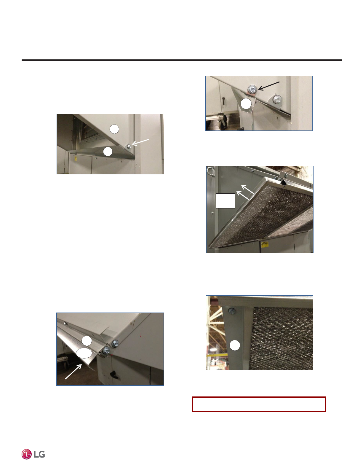
14.
15.
Attach the ALUM FILTER BOTTOM (item
#12, if applicable) by aligning the bottom tab
holes with the dimples on both triangles, as
shown below. Fasten with the provided 5/16″
hex-head screws.
9
12
Step 14: Install aluminum filter bottom, if applicable.
For 110/210 casing:
Attach the top and bottom FILTER RAILS
(item #13A) to the side HOOD TRIANGLES
by aligning the ALUM FILTER RAIL tab
with dimples on both triangles. Fasten
holes
with the provided 5/16″ hex-head screws.
Refer to both of the following figures.
For 310 casing:
Install item #13B as the top filter rail. Install
one item #13A as the bottom filter rail.
16.
13A
Step 15b: Location of bottom filter rail, item #13A.
Install ALUM FILTERS (item #1A and 1B).
Verify airflow arrow is facing into the unit.
Airflow
Direction
Installation
Step 16: Install filters with arrow pointing into the unit.
For 310/350/352 casing:
Install the additional #13A filter rails at the
midpoint of the hood triangles. Align the filter
rail tab holes with dimples on both triangles.
The top middle rail should face up and the
bottom middle rail should face down.
3
13A/B
Step 15a: Location of top filter rail, item #13A.
This is item #13B o
n the 310 casing only.
17.
Fasten SIDE SPACERS (item #14) to
bottom flange of both triangles to secure the
filters.
14
Step 17: Install side spacers.
OA Hood assembly with filters is complete.
Due to our policy of continuous product innovation, some specifications may change without notification.
©LG Electronics U.S.A., Inc., Englewood Cliffs, NJ. All rights reserved. “LG” is a registered trademark of LG Corp.
29
OUTDOOR AIR HOOD ASSEMBLY
Part Number (Quantity)
350 Casing ALL
VPRE/C/P
Description
2
SCREEN SIDE SUPPORT
5657
2501 (2)
2506 (2)
2511 (2)
2035 (2)
4615 (2)
3
HOOD END
5656
2502 (1)
2507 (1)
2512 (1)
2038 (1)
4619 (1)
4
SCREEN CENTER SUPPORT
N/A
2503 (1)
2508 (1)
2513 (1)
2036 (3)
4894 (3)
5
SCREEN SUPPORTFLASHING
N/A
2504 (1)
2509 (1)
2514 (1)
2498 (3)
4895 (3)
6
HOOD TOP-A
5712
2500 (1)
2505 (1)
2510 (1)
N/A
N/A
7
HOOD TOP-B
N/A
N/A
N/A
N/A
2032 (1)
4612 (1)
8
HOOD TOP-C
N/A
N/A
N/A
N/A
2037 (1)
4616 (1)
9
RIGHT SIDE TRIANGLE
5713
1317 (1)
4087 (1)
8087 (1)
2033 (1)
4613 (1)
10
LEFT SIDE TRIANGLE
5714
1318 (1)
4088 (1)
8088 (1)
2034 (1)
4614 (1)
11
BOTTOM FLASHING
5728
1229 (1)
4297 (1)
8297 (1)
2039 (1)
4617 (1)
15
FRAMED BIRD SCREEN
20.88x37.50
25.50x45.50
28.00x57.75 (1)
39.38x64.63 (1)
46.50x52.75 (2)
46.50x57.75 (2)
—
FRAMED BIRD SCREEN PART#
1016711
1009801 (1)
1009802 (1)
1009803 (1)
1009804 (2)
1015153 (2)
•
Item # 2 is shipped pre-installed to items #9 and #10 from the factory.
The outdoor air hood on all VPRC/P units is located at the bottom of the unit.
Intake Hood with Bird Screen
Item #
V10 Casing
Rooftop Dedicated Outdoor Air System Installation Manual
•
30
Due to our policy of continuous product innovation, some specifications may change without notification.
©LG Electronics U.S.A., Inc., Englewood Cliffs, NJ. All rights reserved. “LG” is a registered trademark of LG Corp.
110 Casing 210 Casing 310 Casing
352 Casing
352 Casing
VPR/VPRX
 Loading...