

Page 1

Lexmark X215 MFP
• Table of Contents
• Start Diagnostics
• Safety and Notices
• Trademarks
4038-001
•Index
Lexmark and Lexmark with diamond
design are trademarks of Lexmark
International, Inc., registered in the
United States and/or other countries.
Page 2

4038-001
Edition: March 24, 2006
The following paragraph does not apply to any country where such provisions are
inconsistent with local law: LEXMARK INTERNATIONAL, INC. PROVIDES THIS
PUBLICATION “AS IS” WITHOUT WARRANTY OF ANY KIND, EITHER EXPRESS OR
IMPLIED, INCLUDING, BUT NOT LIMITED TO, THE IMPLIED WARRANTIES OF
MERCHANTABILITY OR FITNESS FOR A PARTICULAR PURPOSE. Some states do
not allow disclaimer of express or implied warranties in certain transactions; therefore,
this statement may not apply to you.
This publication could include technical inaccuracies or typographical errors. Changes
are periodically made to the information herein; these changes will be incorporated in
later editions. Improvements or changes in the products or the programs described may
be made at any time.
Comments may be addressed to Lexmark International, Inc., Department D22A/032-2,
740 West New Circle Road, Lexington, Kentucky 40550, U.S.A or e-mail at
ServiceInfoAndTraining@Lexmark.com. Lexmark may use or distribute any of the
information you supply in any way it believes appropriate without incurring any obligation
to you.
Lexmark, and Lexmark with diamond design are trademarks of Lexmark International,
Inc., registered in the United States and/or other countries.
All other trademarks are the property of their respective owners.
© 2003, 2004 Lexmark International, Inc.
All rights reserved.
UNITED STATES GOVERNMENT RIGHTS
This software and any accompanying documentation provided under this agreement are
commercial computer software and documentation developed exclusively at private
expense.
U.S.A. P/N 12G9321
Page 3

4038-001
Table of contents
Laser notices. . . . . . . . . . . . . . . . . . . . . . . . . . . . . . . . . . . . . . . . . . . vii
Safety information. . . . . . . . . . . . . . . . . . . . . . . . . . . . . . . . . . . . . . xvii
Preface . . . . . . . . . . . . . . . . . . . . . . . . . . . . . . . . . . . . . . . . . . . . . . . xxii
Definitions . . . . . . . . . . . . . . . . . . . . . . . . . . . . . . . . . . . . . . . . . . xxii
General information . . . . . . . . . . . . . . . . . . . . . . . . . . . . . . . . . . . . 1-1
Machine features . . . . . . . . . . . . . . . . . . . . . . . . . . . . . . . . . . 1-1
Print materials. . . . . . . . . . . . . . . . . . . . . . . . . . . . . . . . . . . . . 1-2
Cleaning the machine. . . . . . . . . . . . . . . . . . . . . . . . . . . . . . . 1-5
Cleaning the outside of the machine. . . . . . . . . . . . . . . . . . . . 1-5
Cleaning the inside of the machine. . . . . . . . . . . . . . . . . . . . . 1-6
Cleaning the scan unit. . . . . . . . . . . . . . . . . . . . . . . . . . . . . . . 1-8
Cleaning the photoconductor drum. . . . . . . . . . . . . . . . . . . . . 1-9
Maintenance approach . . . . . . . . . . . . . . . . . . . . . . . . . . . . . . 1-9
Tools. . . . . . . . . . . . . . . . . . . . . . . . . . . . . . . . . . . . . . . . . . . . 1-9
Abbreviations . . . . . . . . . . . . . . . . . . . . . . . . . . . . . . . . . . . . 1-10
Diagnostic information . . . . . . . . . . . . . . . . . . . . . . . . . . . . . . . . . 2-1
Start . . . . . . . . . . . . . . . . . . . . . . . . . . . . . . . . . . . . . . . . . . . . . . . 2-1
Error message table . . . . . . . . . . . . . . . . . . . . . . . . . . . . . . . . 2-2
Symptom table . . . . . . . . . . . . . . . . . . . . . . . . . . . . . . . . . . . 2-10
Paper feed problems . . . . . . . . . . . . . . . . . . . . . . . . . . . . . . 2-11
Printing and copying problems . . . . . . . . . . . . . . . . . . . . . . . 2-13
Scanning problems . . . . . . . . . . . . . . . . . . . . . . . . . . . . . . . 2-18
Faxing problems . . . . . . . . . . . . . . . . . . . . . . . . . . . . . . . . . . 2-19
Print quality checks. . . . . . . . . . . . . . . . . . . . . . . . . . . . . . . . 2-21
Service checks . . . . . . . . . . . . . . . . . . . . . . . . . . . . . . . . . . . 2-30
Diagnostic aids . . . . . . . . . . . . . . . . . . . . . . . . . . . . . . . . . . . . . . . . 3-1
Configuration modes . . . . . . . . . . . . . . . . . . . . . . . . . . . . . . . . . . 3-1
Clear All Memory mode. . . . . . . . . . . . . . . . . . . . . . . . . . . . . . 3-1
Clear Count mode. . . . . . . . . . . . . . . . . . . . . . . . . . . . . . . . . . 3-2
Dial mode . . . . . . . . . . . . . . . . . . . . . . . . . . . . . . . . . . . . . . . . 3-3
Error Rate mode . . . . . . . . . . . . . . . . . . . . . . . . . . . . . . . . . . . 3-3
Modem Speed mode. . . . . . . . . . . . . . . . . . . . . . . . . . . . . . . . 3-4
Park CCD module mode. . . . . . . . . . . . . . . . . . . . . . . . . . . . . 3-5
Print Properties mode. . . . . . . . . . . . . . . . . . . . . . . . . . . . . . . 3-6
Send Level mode . . . . . . . . . . . . . . . . . . . . . . . . . . . . . . . . . . 3-8
System Settings Report mode . . . . . . . . . . . . . . . . . . . . . . . . 3-8
iii
Page 4

4038-001
Machine tests . . . . . . . . . . . . . . . . . . . . . . . . . . . . . . . . . . . . . . . .3-9
DRAM Memory test . . . . . . . . . . . . . . . . . . . . . . . . . . . . . . . . .3-9
Modem Protocol Log test. . . . . . . . . . . . . . . . . . . . . . . . . . . .3-10
Modem test. . . . . . . . . . . . . . . . . . . . . . . . . . . . . . . . . . . . . . .3-10
Motor, Fan, Solenoid test. . . . . . . . . . . . . . . . . . . . . . . . . . . .3-11
Operator Panel Button test. . . . . . . . . . . . . . . . . . . . . . . . . . .3-12
Operator Panel test . . . . . . . . . . . . . . . . . . . . . . . . . . . . . . . .3-13
Printhead test. . . . . . . . . . . . . . . . . . . . . . . . . . . . . . . . . . . . .3-14
Print Quality Pages test . . . . . . . . . . . . . . . . . . . . . . . . . . . . .3-15
ROM Memory test . . . . . . . . . . . . . . . . . . . . . . . . . . . . . . . . .3-16
Scanner CCD Module and Motor test . . . . . . . . . . . . . . . . . .3-17
Sensor test. . . . . . . . . . . . . . . . . . . . . . . . . . . . . . . . . . . . . . .3-17
Customizing settings . . . . . . . . . . . . . . . . . . . . . . . . . . . . . . . . .3-19
Content. . . . . . . . . . . . . . . . . . . . . . . . . . . . . . . . . . . . . . . . . .3-19
Darkness . . . . . . . . . . . . . . . . . . . . . . . . . . . . . . . . . . . . . . . .3-20
Number. . . . . . . . . . . . . . . . . . . . . . . . . . . . . . . . . . . . . . . . . .3-20
Scale . . . . . . . . . . . . . . . . . . . . . . . . . . . . . . . . . . . . . . . . . . .3-21
Advanced . . . . . . . . . . . . . . . . . . . . . . . . . . . . . . . . . . . . . . . .3-22
Repair information . . . . . . . . . . . . . . . . . . . . . . . . . . . . . . . . . . . . . .4-1
Removals . . . . . . . . . . . . . . . . . . . . . . . . . . . . . . . . . . . . . . . . . . .4-1
Covers . . . . . . . . . . . . . . . . . . . . . . . . . . . . . . . . . . . . . . . . . . .4-1
Automatic document feed (ADF) removals . . . . . . . . . . . . . .4-17
CCD module assembly removal. . . . . . . . . . . . . . . . . . . . . . .4-19
Fan removal . . . . . . . . . . . . . . . . . . . . . . . . . . . . . . . . . . . . . .4-31
Fuser removal . . . . . . . . . . . . . . . . . . . . . . . . . . . . . . . . . . . .4-32
HVPS contact removal. . . . . . . . . . . . . . . . . . . . . . . . . . . . . .4-33
LVPS / HVPS card removal . . . . . . . . . . . . . . . . . . . . . . . . . .4-34
Main drive assembly removal . . . . . . . . . . . . . . . . . . . . . . . . .4-37
Main paper feed roller removal . . . . . . . . . . . . . . . . . . . . . . . .4-39
Main feed roller solenoid removal . . . . . . . . . . . . . . . . . . . . .4-42
Manual paper feed sensor actuator removal . . . . . . . . . . . . .4-45
Modem card removal . . . . . . . . . . . . . . . . . . . . . . . . . . . . . . .4-47
Operator panel removal . . . . . . . . . . . . . . . . . . . . . . . . . . . . .4-50
Paper empty sensor actuator removal . . . . . . . . . . . . . . . . . .4-52
Paper feed sensor actuator removal . . . . . . . . . . . . . . . . . . .4-54
Paper tray feed roller removal . . . . . . . . . . . . . . . . . . . . . . . .4-56
Paper tray pick roller assembly removal . . . . . . . . . . . . . . . .4-57
Paper tray solenoid removal. . . . . . . . . . . . . . . . . . . . . . . . . .4-61
Printhead removal . . . . . . . . . . . . . . . . . . . . . . . . . . . . . . . . .4-63
Scanner assembly removal . . . . . . . . . . . . . . . . . . . . . . . . . .4-64
Scanner card assembly removal . . . . . . . . . . . . . . . . . . . . . .4-68
Scanner assembly cushion removal. . . . . . . . . . . . . . . . . . . .4-71
iv Service Manual
Page 5

4038-001
Scanner assembly hinge removal. . . . . . . . . . . . . . . . . . . . . 4-72
System board removal . . . . . . . . . . . . . . . . . . . . . . . . . . . . . 4-73
Transfer roll removal. . . . . . . . . . . . . . . . . . . . . . . . . . . . . . . 4-76
Locations . . . . . . . . . . . . . . . . . . . . . . . . . . . . . . . . . . . . . . . . . . . . 5-1
Front view . . . . . . . . . . . . . . . . . . . . . . . . . . . . . . . . . . . . . . . . 5-1
Rear view . . . . . . . . . . . . . . . . . . . . . . . . . . . . . . . . . . . . . . . . 5-2
EP rollers. . . . . . . . . . . . . . . . . . . . . . . . . . . . . . . . . . . . . . . . . 5-3
Operator panel . . . . . . . . . . . . . . . . . . . . . . . . . . . . . . . . . . . . 5-4
HVPS / LVPS card . . . . . . . . . . . . . . . . . . . . . . . . . . . . . . . . . 5-6
Modem card . . . . . . . . . . . . . . . . . . . . . . . . . . . . . . . . . . . . . . 5-8
Operator panel card . . . . . . . . . . . . . . . . . . . . . . . . . . . . . . . . 5-9
Scanner card . . . . . . . . . . . . . . . . . . . . . . . . . . . . . . . . . . . . 5-10
System board . . . . . . . . . . . . . . . . . . . . . . . . . . . . . . . . . . . . 5-12
ADF paper path . . . . . . . . . . . . . . . . . . . . . . . . . . . . . . . . . . 5-14
Printer engine paper path/paper jams. . . . . . . . . . . . . . . . . . 5-15
Preventive maintenance . . . . . . . . . . . . . . . . . . . . . . . . . . . . . . . . 6-1
Parts catalog . . . . . . . . . . . . . . . . . . . . . . . . . . . . . . . . . . . . . . . . . . 7-1
How to use this parts catalog . . . . . . . . . . . . . . . . . . . . . . . . . . . 7-1
Assembly 1: Scanner assembly . . . . . . . . . . . . . . . . . . . . . . . . . . .2
Assembly 2: Main assembly. . . . . . . . . . . . . . . . . . . . . . . . . . . . . . .4
Assembly 3: Frame assembly . . . . . . . . . . . . . . . . . . . . . . . . . . . . .6
Index . . . . . . . . . . . . . . . . . . . . . . . . . . . . . . . . . . . . . . . . . . . . . . . . .I-1
Part number index . . . . . . . . . . . . . . . . . . . . . . . . . . . . . . . . . . . . . .I-5
v
Page 6

4038-001
vi Service Manual
Page 7
4038-001
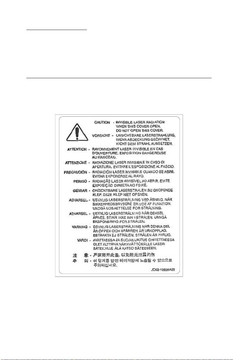
Laser notices
The following laser notice labels may be affixed to this printer as
shown.
Laser advisory label
With the middle cover removed, the laser advisory label is affixed to
the top of the printhead.
Laser notices vii
Page 8

4038-001
Class 1 Laser Statement label
The Class 1 laser label is located on the rear of the machine.
Example:
viii Service Manual
Page 9

4038-001
Laser notice
The printer is certified in the U.S. to conform to the requirements of
DHHS 21 CFR Subchapter J for Class I (1) laser products, and
elsewhere is certified as a Class I laser product conforming to the
requirements of IEC 60825-1.
Class I laser products are not considered to be hazardous. The
printer contains internally a Class IIIb (3b) laser that is nominally a 5
milliwatt gallium arsenide laser operating in the wavelength region of
770-795 nanometers. The laser system and printer are designed so
there is never any human access to laser radiation above a Class I
level during normal operation, user maintenance, or prescribed
service condition.
Laser
Der Drucker erfüllt gemäß amtlicher Bestätigu n g der USA die
Anforderungen der Bestimmung DHHS (Department of Health and
Human Services) 21 CFR Teil J für Laserprodukte der Klasse I (1).
In anderen Ländern gilt der Drucker als Laserprodukt der Klasse I,
der die Anforderungen der IEC (International Electrotechnical
Commission) 60825-1 gemäß amtlicher Bestätigung erfüllt.
Laserprodukte der Klasse I gelten als unschädlich. Im Inneren des
Druckers befindet sich ein Laser der Klasse IIIb (3b), bei dem es
sich um einen Galliumarsenlaser mit 5 Milliwatt handelt, der Wellen
der Länge 770-795 Nanometer ausstrahlt. Das Lasersystem und der
Drucker sind so konzipiert, daß im Normalbetrieb, bei der Wartung
durch den Benutzer oder bei ordnungsgemäßer Wartung durch den
Kundendienst Laserbestrahlung, die die Klasse I überste igen würde,
Menschen keinesfalls erreicht.
Laser notices ix
Page 10

4038-001
Avis relatif à l’utilisation de laser
Pour les Etats-Unis : cette imprimante est certifiée conforme aux
provisions DHHS 21 CFR alinéa J concernant les produits laser de
Classe I (1). Pour les autres pays : cette imprimante répond aux
normes IEC 60825-1 relatives aux produits laser de Class e I.
Les produits laser de Classe I sont considérés comme des produits
non dangereux. Cette imprimante est équipée d’un laser de Classe
IIIb (3b) (arséniure de gallium d’une puissance nominale de 5
milliwatts) émettant sur des longueurs d’onde comprises entre 770
et 795 nanomètres. L’imprimante et son système laser sont conçus
pour impossible, dans des conditions normales d’utilisation,
d’entretien par l’utilisateur ou de révision, l’exposition à des
rayonnements laser supérieurs à des rayonnements de Classe I .
Avvertenze sui prodotti laser
Questa stampante è certificata negli Stati Uniti per essere conforme
ai requisiti del DHHS 21 CFR Sottocapitolo J per i prodotti laser di
classe 1 ed è certificata negli altri Paesi come prodotto laser di
classe 1 conforme ai requisiti della norma CEI 60825-1.
I prodotti laser di classe non sono considerati pericolosi. La
stampante contiene al suo interno un laser di classe IIIb (3b)
all’arseniuro di gallio della potenza di 5mW che opera sulla
lunghezza d’onda compresa tra 770 e 795 nanometri. Il sistema
laser e la stampante sono stati progettati in modo tale che le
persone a contatto con la stampante, durante il normale
funzionamento, le operazioni di servizio o quelle di assistenza
tecnica, non ricevano radiazioni laser superiori al livello della classe
1.
x Service Manual
Page 11

4038-001
Avisos sobre el láser
Se certifica que, en los EE.UU., esta impresora cumple los
requisitos para los productos láser de Clase I (1) establecidos en el
subcapítulo J de la norma CFR 21 del DHHS (Departamento de
Sanidad y Servicios) y, en los demás países, reúne todas las
condiciones expuestas en la norma IEC 60825-1 para productos
láser de Clase I (1).
Los productos láser de Clase I no se consideran peligrosos. La
impresora contiene en su interior un láser de Clase IIIb (3b) de
arseniuro de galio de funcionamiento nominal a 5 milivatios en una
longitud de onda de 770 a 795 nanómetros. El sistema láser y la
impresora están diseñados de forma que ninguna persona pueda
verse afectada por ningún tipo de radiación láser su perior al nivel de
la Clase I durante su uso normal, el mantenimiento realizado por el
usuario o cualquier otra situación de servicio técnico.
Declaração sobre Laser
A impressora está certificada nos E.U.A. em conformidade com os
requisitos da regulamentação DHHS 21 CFR Subcapítulo J para a
Classe I (1) de produtos laser. Em outros locais, está certificada
como um produto laser da Classe I, em conformidade com os
requisitos da norma IEC 60825-1.
Os produtos laser da Classe I não são considerados perigosos.
Internamente, a impressora contém um produto laser da Classe IIIb
(3b), designado laser de arseneto de potássio, de 5 milliwatts
,operando numa faixa de comprim en to de ond a en tr e 77 0 e 79 5
nanómetros. O sistema e a impressora laser foram concebidos de
forma a nunca existir qualquer possiblidade de acesso humano a
radiação laser superior a um nível de Classe I durante a operação
normal, a manutenção feita pelo utilizador ou condições de
assistência prescritas.
Laser notices xi
Page 12

4038-001
Laserinformatie
De printer voldoet aan de eisen die gesteld worden aan een
laserprodukt van klasse I. Voor de Verenigde Staten zijn deze eisen
vastgelegd in DHHS 21 CFR Subchapter J, voor andere landen in
IEC 60825-1.
Laserprodukten van klasse I worden niet als ongevaarlijk
aangemerkt. De printer is voorzien van een laser van klasse IIIb
(3b), dat wil zeggen een gallium arsenide-laser van 5 milliwatt met
een golflengte van 770-795 nanometer. Het lasergedeelte en de
printer zijn zo ontworpen dat bij normaal gebruik, bij onderhoud of
reparatie conform de voorschriften, nooit blootstelling mogelijk is
aan laserstraling boven een niveau zoals voorgeschreven is voor
klasse 1.
Lasermeddelelse
Printeren er godkendt som et Klasse I-laserprodukt, i
overenstemmelse med kravene i IEC 60825-1.
Klasse I-laserprodukter betragtes ikke som farlige. Printeren
indeholder internt en Klasse IIIB (3b)-laser, der nominelt er en 5
milliwatt galliumarsenid laser, som arbejder på bølgelængdeområdet
770-795 nanometer. Lasersystemet og printeren er udformet
således, at mennesker aldrig udsættes for en laserstråling over
Klasse I-niveau ved normal drift, brugervedligeholdelse eller
obligatoriske servicebetingelser.
xii Service Manual
Page 13

4038-001
Huomautus laserlaitteesta
Tämä kirjoitin on Yhdysvalloissa luokan I (1) laserlaitteiden DHHS
21 CFR Subchapter J -määrityksen mukainen ja muualla luokan I
laserlaitteiden IEC 60825-1 -määrityksen mukainen.
Luokan I laserlaitteiden ei katsota olevan vaarallisia käyttäjälle.
Kirjoittimessa on sisäinen luokan IIIb (3b) 5 milliwatin
galliumarsenidilaser, joka toimii aaltoalueella 770 - 795 nanometriä.
Laserjärjestelmä ja kirjoitin on suunniteltu siten, että käyttäjä ei
altistu luokan I määrityksiä voimakkaammalle säteilylle kirjoittimen
normaalin toiminnan, käyttäjän tekemien huoltotoimien tai muiden
huoltotoimien yhteydessä.
VARO! Avattaessa ja suojalukitus ohitettaessa olet alttiina
näkymättömälle lasersäteilylle. Älä katso säteeseen.
VARNING! Osynlig laserstrålning när denna del är öppnad och
spärren är urkopplad. Betrakta ej strålen.
Laser-notis
Denna skrivare är i USA certifierad att motsvara kraven i DHHS 21
CFR, underparagraf J för laserprodukter av Klass I (1). I andra
länder uppfyller skrivaren kraven för laserprodukter av Klass I enligt
kraven i IEC 60825-1.
Laserprodukter i Klass I anses ej hälsovådliga. Skrivaren har en
inbyggd laser av Klass IIIb (3b) som består av en laserenhet av
gallium-arsenid på 5 milliwatt som arbetar i våglängdsområdet 770795 nanometer . Lasersystemet och skrivaren är utformade så att det
aldrig finns risk för att någon person utsätts för laserstrålning över
Klass I-nivå vid normal användning, underhåll som utfö rs av
användaren eller annan föreskriven serviceåtgärd.
Laser notices xiii
Page 14

4038-001
Laser-melding
Skriveren er godkjent i USA etter kravene i DHHS 21 CFR,
underkapittel J, for klasse I (1) laserprodukter, og er i andre land
godkjent som et Klasse I-laserprodukt i samsvar med kravene i IEC
60825-1.
Klasse I-laserprodukter er ikke å betrakte som farlige. Skriveren
inneholder internt en klasse IIIb (3b)-laser, som består av en
gallium-arsenlaserenhet som avgir stråling i bølgelengdeområdet
770-795 nanometer. Lasersystemet og skriveren er utformet slik at
personer aldri utsettes for laserstråling ut over klasse I-nivå under
vanlig bruk, vedlikehold som utføres av brukeren, eller foreskrevne
serviceoperasjoner.
Avís sobre el Làser
Segons ha estat certificat als Estats Units, aquesta impressora
compleix els requisits de DHHS 21 CFR, apartat J, pels productes
làser de classe I (1), i segons ha estat certificat en altres llocs, és un
producte làser de classe I que compleix els requisits d’IEC 60825-1.
Els productes làser de classe I no es consideren perillosos. Aquesta
impressora conté un làser de classe IIIb (3b) d’arseniür de gal.li,
nominalment de 5 mil.liwats, i funciona a la regió de longitud d’ona
de 770-795 nanòmetres. El sistema làser i la impressora han sigut
concebuts de manera que mai hi hagi exposició a la radiació làser
per sobre d’un nivell de classe I durant una operació normal, durant
les tasques de manteniment d’usuari ni durant els serveis que
satisfacin les condicions prescrites.
xiv Service Manual
Page 15
Japanese Laser Notice
Chinese Laser Notice
4038-001
Laser notices xv
Page 16
4038-001
Korean Laser Notice
xvi Service Manual
Page 17

Safety information
• The safety of this product is based on testing and approvals of
the original design and specific components. The manufacturer
is not responsible for safety in the event of use of unauthorized
replacement parts.
• The maintenance information for this product has been
prepared for use by a professional service person and is not
intended to be used by others.
• There may be an increased risk of electric shock and personal
injury during disassembly and servicing of this product.
Professional service personnel should understand this and take
necessary precautions.
• CAUTION: When you see this symbol, there is a
danger from hazardous voltage in the area of the
product where you are working. Unplug the product
before you begin, or use caution if the product must
receive power in order to perform the task.
Consignes de sécurité
4038-001
• La sécurité de ce produit repose sur des tests et des
agréations portant sur sa conception d'origine et sur des
composants particuliers. Le fabricant n'assume aucune
responsabilité concernant la sécurité en cas d'utilisation de
pièces de rechange non agréées.
• Les consignes d'entretien et de réparation de ce produit
s'adressent uniquement à un personnel de maintenance
qualifié.
• Le démontage et l'entretien de ce produit pouvant présenter
certains risques électriques, le personne l d'en tr et ien qu alifié
devra prendre toutes les précautions nécessaires.
• ATTENTION : Ce symbole indique la présence
d'une tension dangereuse dans la partie du produit
sur laquelle vous travaillez. Débranchez le produit
avant de commencer ou faites preuve de vigilance si
l'exécution de la tâche exige que le pr oduit reste sous
tension.
Safety information xvii
Page 18

4038-001
Norme di sicurezza
• La sicurezza del prodotto si basa sui test e sull'approvazione
del progetto originale e dei componenti specifici. Il produttore
non è responsabile per la sicurezza in caso di sostituzione non
autorizzata delle parti.
• Le informazioni riguardanti la manutenzione di questo prodotto
sono indirizzate soltanto al personale di assistenza autorizzato.
• Durante lo smontaggio e la manutenzione di questo prodotto,
il rischio di subire scosse elettriche e danni alla persona è più
elevato. Il personale di assistenza autorizzato deve, quindi,
adottare le precauzioni necessarie.
• ATTENZIONE: Questo simbolo indica la presenza
di tensione pericolosa nell'area del prodotto.
Scollegare il prodotto prima di iniziare o usare cautela
se il prodotto deve essere alimentato per eseguire
l'intervento.
Sicherheitshinweise
• Die Sicherheit dieses Produkts basiert auf Tests und
Zulassungen des ursprünglichen Modells und bestimmter
Bauteile. Bei Verwendung nicht genehmigter Ersatzteile wird
vom Hersteller keine Verantwortung oder Haftung für die
Sicherheit übernommen.
• Die Wartungsinformationen für dieses Produkt sind
ausschließlich für die Verwendung durch einen
Wartungsfachmann bestimmt.
• Während des Auseinandernehmens und der Wartung des
Geräts besteht ein zusätzliches Risiko eines elektrischen
Schlags und körperlicher Verl etzung. Das zuständige
Fachpersonal sollte entsprechende Vorsichtsmaßnahmen
treffen.
• ACHTUNG: Dieses Symbol weist auf eine
gefährliche elektrische Spannung hin, die in diesem
Bereich des Produkts auftreten kann. Ziehen Sie vor
den Arbeiten am Gerät den Netzstecker des Geräts,
bzw. arbeiten Sie mit großer Vorsicht, wenn das
Produkt für die Ausführung der Arbeiten an den
Strom angeschlossen sein muß.
xviii Service Manual
Page 19

Pautas de Seguridad
• La seguridad de este producto se basa en pruebas y
aprobaciones del diseño original y componentes específicos.
El fabricante no es responsable de la seguridad en caso de uso
de piezas de repuesto no autorizadas.
• La información sobre el mantenimiento de este producto está
dirigida exclusivamente al personal cualificado de
mantenimiento.
• Existe mayor riesgo de descarga eléctrica y de daños
personales durante el desmontaje y la reparación de la
máquina. El personal cualificado debe ser consciente de este
peligro y tomar las precauciones necesarias.
• PRECAUCIÓN: este símbolo indica que el voltaje
de la parte del equipo con la que está trabajando es
peligroso. Antes de empezar, desenchufe el equipo
o tenga cuidado si, para trabajar con él, debe
conectarlo.
Informações de Segurança
4038-001
• A segurança deste produto baseia-se em testes e aprovações
do modelo original e de componentes específicos. O fabricante
não é responsável pela segunrança, no caso de uso de peças
de substituição não autorizadas.
• As informações de segurança relativas a este produto
destinam-se a profissionais destes serviços e não devem ser
utilizadas por outras pessoas.
• Risco de choques eléctricos e ferimentos graves durante a
desmontagem e manutenção deste produto. Os profissionais
destes serviços devem estar avisados deste facto e tomar os
cuidados necessários.
• CUIDADO: Quando vir este símbolo, existe a
possível presença de uma potencial tensão perigosa
na zona do produto em que está a trabalhar. Antes
de começar, desligue o produto da tomada eléctrica
ou seja cuidadoso caso o produto tenha de estar
ligado à corrente eléctrica para realizar a tarefa
necessária.
Safety information xix
Page 20
4038-001
Informació de Seguretat
• La seguretat d'aquest producte es basa en l'avaluació i
aprovació del disseny original i els components específics.
El fabricant no es fa responsable de les qüestions de
seguretat si s'utilitzen peces de recanvi no autoritzades.
• La informació pel manteniment d’aquest producte està
orientada exclusivament a professionals i no està destinada
a ningú que no ho sigui.
• El risc de xoc elèctric i de danys personals pot augmentar
durant el procés de desmuntatge i de servei d’aquest producte.
El personal professional ha d’estar-ne assabentat i prendre
les mesures convenients.
• PRECAUCIÓ: aquest símbol indica que el voltatge
de la part de l'equip amb la qual esteu treballant és
perillós. Abans de començar, desendolleu l'equip
o extremeu les precaucions si, per treballar amb
l'equip, l'heu de connectar.
xx Service Manual
Page 21
4038-001
Safety information xxi
Page 22

4038-001
Preface
This manual contains maintenance procedures for service
personnel. It is divided into the following chapters:
1. General information contains a general description of the
printer and the maintenance approach used to repair it. Spec ial
tools and test equipment are listed, as well as general
environmental and safety instructions.
2. Diagnostic information contains an error indicator table,
symptom tables, and service checks used to isolate failing field
replaceable units (FRUs).
3. Diagnostic aids contains tests and checks used to locate or
repeat symptoms of printer problems.
4. Repair information provides instructions for making printer
adjustments and removing and installing FRUs.
5. Connector locations uses illustrations to identify the connector
locations and test points on the printer.
6. Preventive maintenance contains the lubrication specifications
and recommendations to prevent problems.
7. Parts catalog contains illustrations and part numbers for
individual FRUs.
Definitions
Note: A note provides additional information.
Warning: A warning identifies something that might damage the
product hardware or software.
CAUTION: A caution identifies something that might cause a
servicer harm.
CAUTION: When you see this symbol, there is a
danger from hazardous voltage in the area of the
product where you are working. Unplug the product
before you begin, or use caution if the product must
receive power in order to perform the task.
xxii Service Manual
Page 23
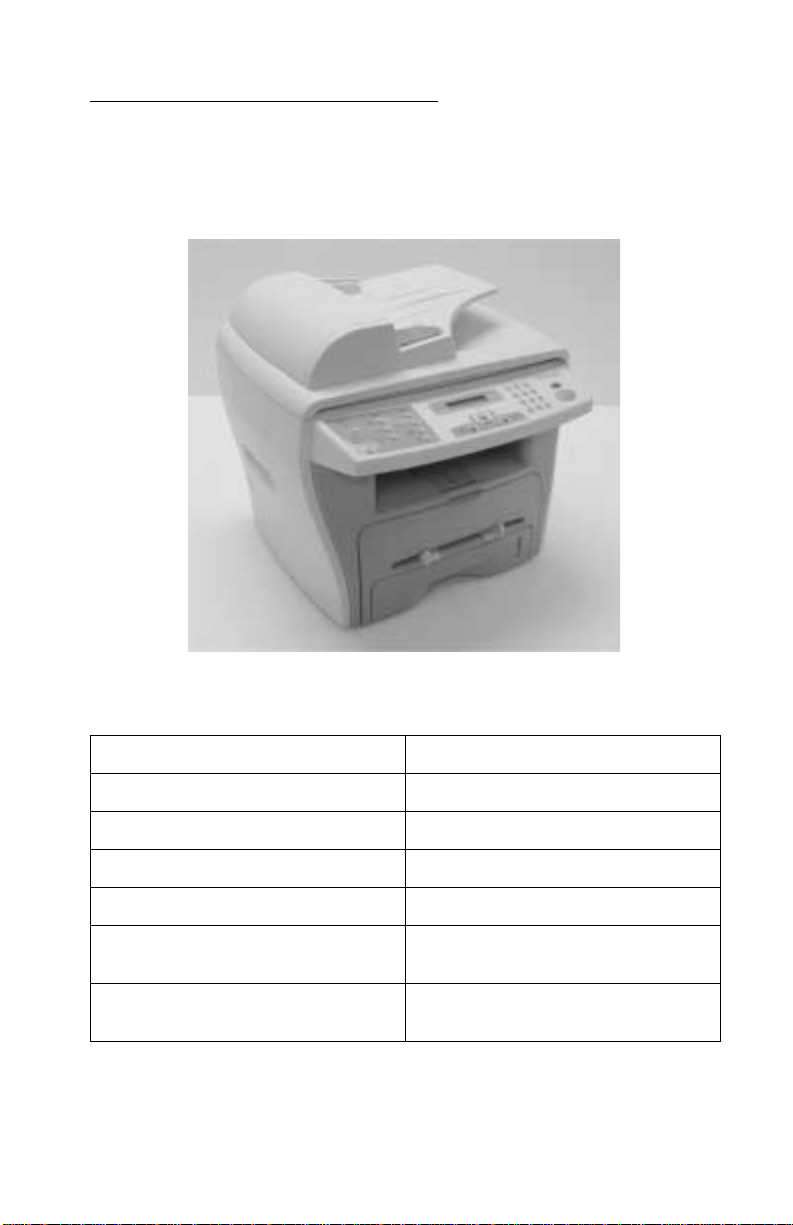
1. General information
The Lexmark™ X215 MFP is a compact multifunction printer that
offers scanning, printing, copying, and faxing.
4038-001
Machine features
Print speeds up to 17 ppm
Print
resolution up to 600 x 600 dpi
P
aper tray capacity up to 250—sheets
ront output bin 150—sheet capacity
F
M
anual bypass paper feeder one page at a time
A
utomatic document feeder
(ADF)
Compatible with various
operating systems
30—sheet capacity
Windows 98, Windows NT 4.0,
Windows 2000, and Windows XP
General information 1-1
Page 24

4038-001
Print materials
Always use print materials that meet the guidelines for use with this
machine. Using print materials not recommended may cause paper
jams or print quality problems.
Selecting print materials
Size (mm/in.)
Plain paper
Letter (215.9 x 279/8.5 x 11)
A4 (210 x 297/8.27 x 11.69)
Folio (215.9 x 330.2/8.5 x 13)
Legal (215.9 x 355.6/8.5 x 14)
Executive (184.2 x 266.7/7.25 x 10.5)
B5 (182 x 257/7.2 x 10)
A5 (148 x 210/5.83 x 8.27)
A6 (105 x 148/4.13 x 5.88)
Envelopes
No.9 (98.4 x 225.4/3.88 x 8.88)
No.10 (104.8 x 241.3/4.12 x 9.5)
DL (110 x 220/4.33 x 8.66)
C5 (162 x 229/6.38 x 9.02)
C6 (114 x 162/4.49 x 6.38)
B5 (176 x 250/6.93 x 9.84)
No.7 3/4 (98.4 x 190.4/3.88 x 5.83)
2
Labels
Letter (215.9 x 279/8.5 x 11)
A4 (210 x 297/8.27 x 11.69)
Transparency films
Letter (215.9 x 279/8.5 x 11)
A4 (210 x 297/8.27 x 11.69)
2
Input source/capacity
Paper tray
Yes/250 Yes/1
No/0 Yes/1
No/0 Yes/1
No/0 Yes/1
No/0 Yes/1
Bypass
feeder
1
1-2 Service Manual
Page 25

4038-001
Input source/capacity
Size (mm/in.)
Paper tray
Card stocks
A6 card (105 x 148/4.13 x 5.88)
Post Card (101.6 x 152.4/4 x 6)
Hagaki (100 x 148/3.94 x 5.83)
1
Maximum capacity may be reduced depending on paper thickness.
2
Media must be fed one sheet at a time through manual bypass.
2
No/0 Yes/1
Paper and speciality media guidelines
When selecting or loading paper, envelopes, transparencies, or
other specialty media, keep these guidelines in mind:
• Attempting to print on damp, curled, wrinkled, or to rn pape r ca n
cause paper jams and poor print quality.
• Use only high quality, copier grade paper. Avoid paper with
embossed lettering, perforations, or texture that is too smooth
or too rough.
• Store paper in its ream wrapper until ready to use. Place
cartons on pallets or shelves, not on the floor. Do not place
heavy objects on top of the paper, whether it is packaged or
loose. Keep it away from moisture, or other conditions that
could cause it to wrinkle or curl.
• During storage, you should use moisture-proof wrap, such as a
plastic container or bag, to prevent dust and moisture from
contaminating your paper.
1
Bypass
feeder
• Always use paper and other materials that conform with those
listed in “Selecting print materials” on page 1-2.
• Use only well-constructed envelopes with sharp, well creased
folds.
• Do not use envelopes with clasps and snaps.
• Do not use envelopes with windows, coated lining, self-
adhesive seals, or other synthetic materials.
• Do not use damaged or poorly made envelopes.
General information 1-3
Page 26

4038-001
• Load specialty media one sheet at a time.
• Use only materials recommended for use with laser printers.
• To prevent specialty media, such as transparencies and label
sheets, from sticking togeth er, remove each sheet from the
output tray as it is printed.
• Place transparencies on a flat surface after removin g them from
the machine.
• Do not leave transparencies in the paper tray for long per iods of
time. Dust and dirt may accumulate on the film, resulting in
spotty printing.
• To avoid smudging caused by fingerprints, handle
transparencies and coated paper carefully.
• To avoid fading, do not expose the printed transparencies to
prolonged sunlight.
• Store unused materials at temperatures between 59
o
F (15
C to 30o C). The relative humidity should be between
10% and 70%.
• The laser printing process heats paper to high temperatures of
180° C (356° F). Use only paper able to withstand these
temperatures without discoloring, bleeding, or releasing
hazardous emissions. Check with the manufacturer or vendor to
determine whether the paper chosen is acceptable for laser
printers.
• Verify that label adhesive materials can tolerate a fusing
temperature of 180
o
C (356o F) for 0.1 second.
o
F and 86o
• Make sure there is no exposed adhesive materia l be twe en
labels. Exposed areas can cause labels to peel off during
printing, which can cause paper jams. Exposed adhesive can
also damage machine components.
• Do not load a sheet of labels through the machine more than
once. The adhesive backing is designed for only on e pa ss
through the machine.
Note: Do not use labels that are separating from the backing sheet
or are wrinkled, bubbled, or damaged.
1-4 Service Manual
Page 27

4038-001
Cleaning the machine
To maintain print quality, follow these cleani ng procedures each time
the toner cartridge is replaced or if print quality problems occur.
• Do not put water directly onto any part of the machine.
• Do not use ammonia-based cleaners or volatile solvents,
such as thinner, on the printer.
• While cleaning the inside of the machine, be careful not to
touch the transfer roller located under the toner cartridge . Oil
from your fingers can affect print quality.
Cleaning the outside of the machine
Wipe the outside surface of the machine with a soft, clean, lint-free
cloth. If you dampen the cloth slightly with water , be careful not to let
any water drip onto or inside the machine.
General information 1-5
Page 28
4038-001
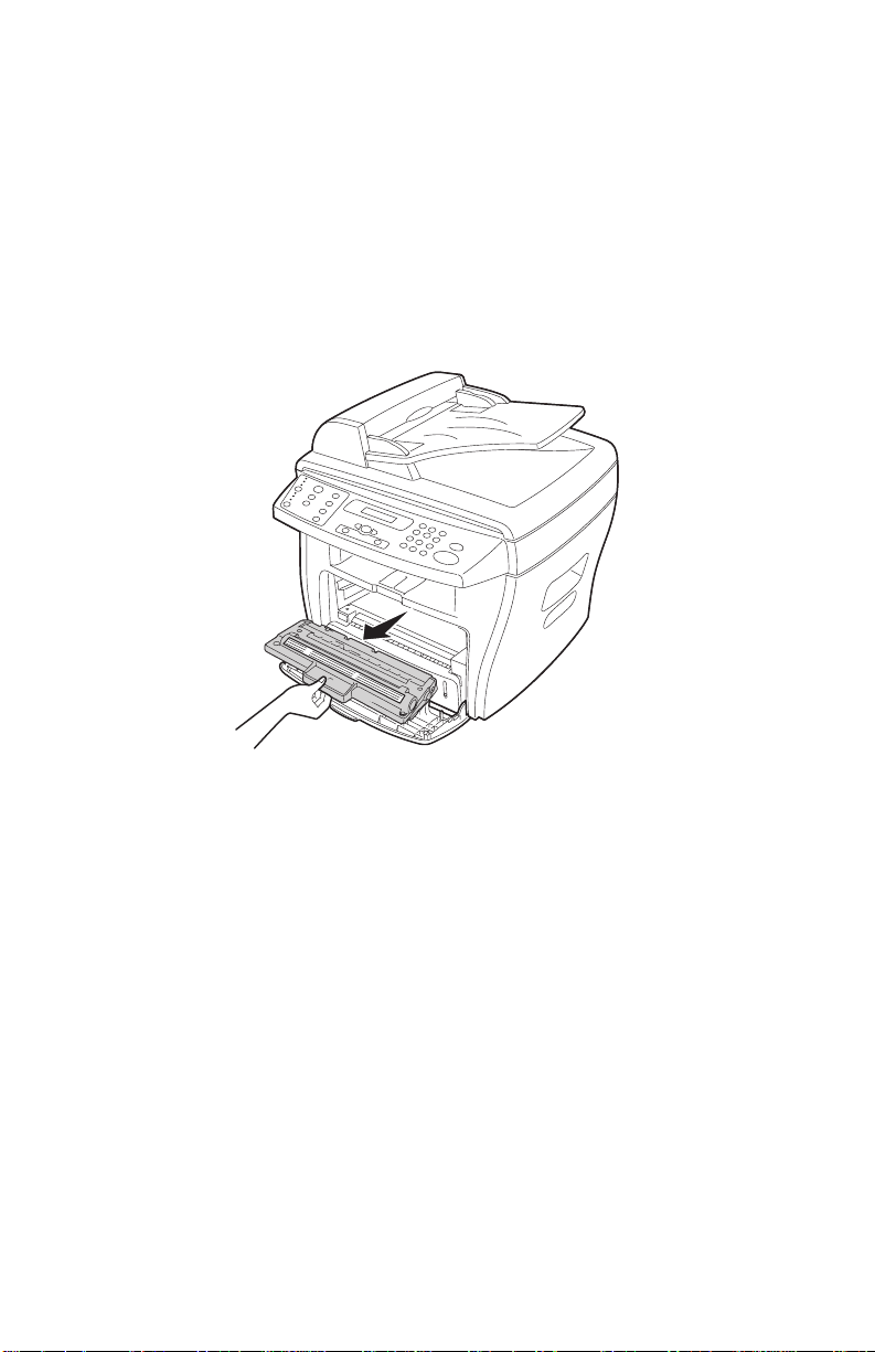
Cleaning the inside of the machine
During the printing process, paper, toner, and dust particles can
accumulate inside the machine. This buildup can cause print quality
problems, such as toner specks or smearing.
1. Turn the machine off, unplug the power cord, and then wait for
the machine to cool down.
2. Open the front cover and remove the toner cartridge.
CAUTION: Do not touch the photoconductor drum located on the
bottom of the toner cartridge.
3. Place the toner cartridge on a clean, dry surface.
1-6 Service Manual
Page 29
4038-001
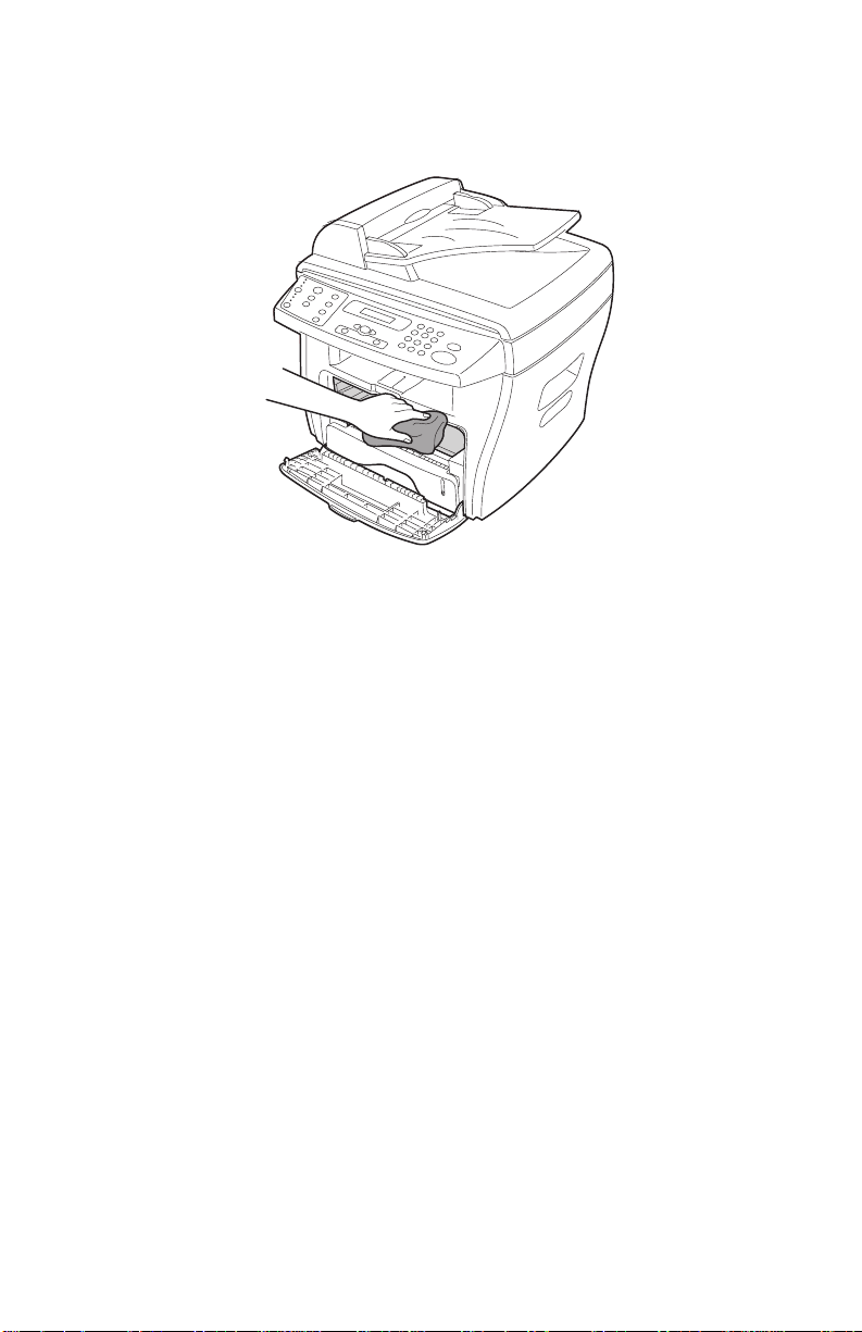
4. With a dry, lint-free cloth, wipe away any dust and spilled toner
from the toner cartridge area and the toner cartridge cavity.
Warning:
• To prevent damage to the toner cartridge, do not expose it to
light for more than a few minutes. Cover it with a piece of paper,
if necessary.
• Do not touch the black transfer roller.
5. Reinsert the toner cartridge and close the cover.
6. Plug in the power cord and turn the machine on.
General information 1-7
Page 30
4038-001
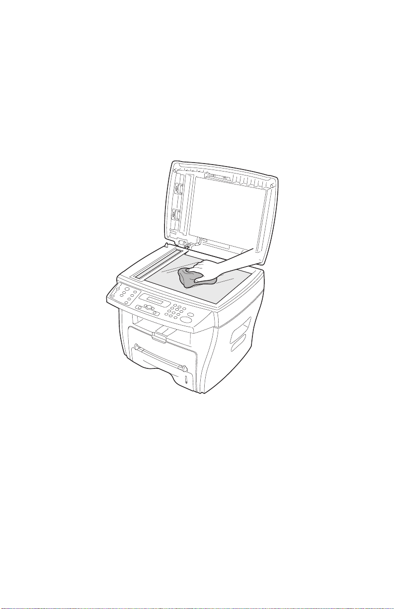
Cleaning the scan unit
Keeping the scan unit clean helps ensure the best po ss ible cop ies .
1. Slightly dampen a soft, lint-free cloth or paper towel with water.
2. Open the document cover.
3. Wipe the surfaces of the document glass and ADF until they are
clean and dry.
4. Wipe the underside of the white document cover and white
sheet until it is clean and dry.
5. Close the document cover.
1-8 Service Manual
Page 31

4038-001
Cleaning the photoconductor drum
If there are streaks or spots on your print, the photoconductor drum
may require cleaning. The operator panel menu includes a Clean
Drum option that may help to improve the print quality.
To clean the photoconductor drum:
1. Make sure paper is loaded.
2. Press Menu until MACHINE SETUP appears on the top line of
the display, and then press Select.
3. Press the scroll button until CLEAN DRUM appears on
the bottom line of the display, and then press Select.
The machine prints out a cleaning page. Toner particles on the
photoconductor surface are affixed to the paper.
If the problem persists, repeat these steps.
If the photoconductor drum has been cleaned several times and the
problem is still unresolved, install a new toner cartridge.
or
Maintenance approach
The diagnostic information in this manual leads you to the correct
field replaceable unit (FRU) or part. Use the error messages, and
diagnostic aids to determine the printer problem and repair the
failure. After you complete the repair, perform tests as needed to
verify the repair.
Tools
The removal and adjustment procedures require the following tools
and equipment:
• Analog or digital multimeter
• Pliers: diagonal and needle-nose
• Screwdrivers: #1 and #2 Phillips
• Cotton swab
When you make voltage readings, always use frame ground unless
another ground is specified.
General information 1-9
Page 32

4038-001
Abbreviations
ADF Automatic document feed
BPS Bits per second
CCD Charge-coupled device
CCITT International consultative committee on telephone
and telegraphy
dB Decibel
DPI Dots per inch
DRAM Dynamic random access memory
EP Electrophotographic process
ESD Electrostatic discharge
FRU Field replaceable unit
HSYNC
HVPS High voltage power supply
Kbps Kilobits per second
LCD Liquid crystal display
LED Light-emitting diode
LSU Laser scan unit
LVPS Low voltage power supply
OPC Optical photoconductor drum
PC Photoconductor
PTL Pre—transfer LED
RH Relative humidity
ROM Read only memory
USB Universal serial bus
V ac Volts alternating current
V dc Volts direct current
1-10 Service Manual
Page 33

4038-001
2. Diagnostic information
Start
CAUTION: NEVER manually actuate or disable the top cover
interlock switch and the printhead shutter actuator at the same time.
To perform some of the service checks and tests, such as
troubleshooting paper feed problems, you need to actuate the top
cover interlock switch with the covers opened or removed and power
applied to the machine. It is important for personal safety that you
DO NOT , FOR ANY REASON, disable the printhead shutter actuator
when power is on.
Remove power from the printer before you connect or
disconnect any cable or electronic board or assembly
for personal safety and to prevent damage to the
printer.
Use the error message table, and symptom table in this chapter to
determine the corrective action necessary to repair a malfunctioning
printer.
The LCD on the operator panel can indicate an error message. See
the “Error message table” on page 2-2 to determine the meaning
of the message and what corrective action to take.
If the printer does not have an error message, go to the “Symptom
table” on page 2-10. Locate the symptom and take appropriate
action to correct the problem.
Diagnostic information 2-1
Page 34

4038-001
Error message table
Clearing display messages:
Display Meaning Solution
Bypass Jam Paper was sensed at
the manual bypass
sensor, but not at the
main paper feed/toner
cartridge present
sensor.
• Load paper in the
manual bypass or
remove the jam from
the manual bypass.
• Make sure the main
paper feed/toner
cartridge present
sensor actuator is
not broken,
improperly installed
or stuck with paper
debris.
• Perform the “Sensor
test” on page 3-17
to check proper
operation of the
sensor.
• If the sensor works
properly, the problem
is likely associated
with the system
board.
• If the paper path and
sensor actuator are
clear and working
properly, and the
problem persists,
replace the HVPS/
LVPS.
Note: This sensor is
a component of the
HVPS/LVPS.
2-2 Service Manual
Page 35

Display Meaning Solution
4038-001
Document Jam Paper was sensed at
the ADF registration
sensor, but not at the
ADF scan sensor.
Door Open Front or rear cover is
not securely latched.
• Make sure the ADF
scan sensor actuator
is not broken,
improperly installed
or stuck with paper
debris.
• If the paper path and
sensor actuator are
clear and working
properly, replace the
scanner assembly.
• Close the front toner
cartridge access
cover until it locks.
• If the message does
not clear, perform the
“Sensor test” on
page 3-17 to check
proper operation of
the switch.
• If the switch works
properly, the problem
is likely associated
with the system
board.
• If the switch does not
work in the test,
make sure the cover
open actuator is
working properly.
When the cover
closes, the cover
should push the
actuator , caus ing th e
cover open switch on
the HVPS/LVPS to
close.
Note: This process
is viewable with the
right cover removed.
• If all moving parts
appear to be working
correctly, and the
messages does not
clear, replace the
HVPS/LVPS.
Diagnostic information 2-3
Page 36

4038-001
Display Meaning Solution
Fuser Error
Load Bypass No document loaded in
LSU Error A problem in the LSU
Memory Full Collated copy is too
No Cartridge Toner cartridge not
Problem in the fuser
unit.
the manual bypass.
(laser scanning unit).
large for memory.
installed.
• Make sure CN1 and
CN7 on the HVPS/
LVPS are properly
connected.
• Check CN1 on the
HVPS/L VPS for
proper voltage.
• If the voltage is
correct, replace the
fuser.
• Otherwise, replace
the HVPS/LVPS.
Load print media into
the manual bypass and
try again.
• Make sure all cables
are properly
connected to the
printhead.
• If correct, replace the
printhead.
Reduce the number of
pages in the job.
Install the toner
cartridge.
No Paper No paper in the paper
tray.
2-4 Service Manual
• If paper exists in the
paper tray but this
message is
displayed, make sure
the paper empty
sensor actuator is
not broken or
improperly installed.
• If the actuator is
working properly,
replace the HVPS/
LVPS.
Page 37

Display Meaning Solution
4038-001
Open Heat Error
Overheat
The printer senses that
the thermistor isn’t
connected or faulty.
The fuser unit has
overheated.
• Make sure the
thermistor is properly
connected to CN7 on
the HVPS/LVPS.
• If the problem
persists replace the
fuser.
Replace the fuser.
Diagnostic information 2-5
Page 38

4038-001
Display Meaning Solution
Paper Jam 0 Paper was sensed at
the paper tray empty
sensor, but not at the
manual bypass.
• Go to the paper path
diagram “Printer
engine paper path/
paper jams” on
page 5-15 to see the
region where a paper
jam may occur.
• Remove any
obstructions and
other paper debris.
• Make sure the
manual bypass
sensor actuator is
not broken,
improperly installed
or stuck with paper
debris.
• Perform the “Sensor
test” on page 3-17
to check proper
operation of the
sensor.
• If the sensor works
properly, the problem
is likely associated
with the system
board.
• If the paper path and
sensor actuator are
clear and working
properly, and the
problem persists,
replace the HVPS/
LVPS.
Note: This sensor is
a component of the
HVPS/LVPS.
2-6 Service Manual
Page 39

Display Meaning Solution
4038-001
Paper Jam 1 The fuser exit sensor
sensed the leading
edge of the page but
never sensed the
trailing edge.
• Go to the paper path
diagram “Printer
engine paper path/
paper jams” on
page 5-15 to see the
region where a paper
jam may occur.
• Remove any
obstructions and
other paper debris.
• Perform the “Sensor
test” on page 3-1 7
to check proper
operation of the
sensor.
• If the sensor works
properly, the problem
is likely associated
with the system
board.
• Make sure the fuser
exit sensor isn’t stuck
with debris or
improperly installed.
• If the paper path and
sensor actuator are
clear and working
properly, replace the
HVPS/LVPS.
Note: This sensor is
a component of the
HVPS/LVPS.
Diagnostic information 2-7
Page 40

4038-001
Display Meaning Solution
Paper Jam 2 Paper was sensed at
the main paper feed/
toner cartridge present
sensor, but not at the
fuser exit sensor.
• Go to the paper path
diagram “Printer
engine paper path/
paper jams” on
page 5-15 to see the
region where a paper
jam may occur.
• Remove any
obstructions and
other paper debris.
• Perform the “Sensor
test” on page 3-17
to check proper
operation of the
sensor.
• If the sensor works
properly, the problem
is likely associated
with the system
board.
• Make sure the fuser
exit sensor actuator
is not broken,
improperly installed
or stuck with paper
debris.
• If the paper path and
sensor actuator are
clear and working
properly, and the
problem persists,
replace the HVPS/
LVPS.
Note: This sensor is
a component of the
HVPS/LVPS.
Power Failure Power interruption and
the machine’s memory
is not saved.
2-8 Service Manual
Restart the print job.
Page 41

Display Meaning Solution
4038-001
Time/Date prompt Prompt appears when
the machine is powered
on.
Toner Empty Toner cartridge has run
out.
Toner Low Toner is nearly empty. Remove the toner
• Use the numeric
keypad to enter the
two-digit month and
day, and the fourdigit year. For
example, 01-23-
2003.
• Enter the current
time. The default
clock setting is 12hour.
• Press the asterisk (*)
to select AM or PM,
and then press
Select.
Note: If the machine
is unplugged for
longer than 15
minutes, or turned off
for longer than an
hour, when the power
is turned back on, the
machine prompts you
to reset the correct
date and time.
Install a new toner
cartridge.
cartridge and gently
shake it. This
temporarily
reestablishes printing.
Diagnostic information 2-9
Page 42

4038-001
Symptom table
Symptom Reference
Paper feed problems See “Paper feed problems” on
page 2-11.
Printing and copying problems See “Printing and copying
Scanning problems See “Scanning problems” on
Faxing problems See “Faxing problems” on
Print quality problems See “Print quality checks” on
Dead machine (no power) See “Dead machine” on
Fan noisy or not working See “Cooling fan” on page 2-30.
Main motor noisy or does not
move
problems” on page 2-13.
page 2-18.
page 2-19.
page 2-21.
page 2-32.
See “Main drive motor” on
page 2-31.
2-10 Service Manual
Page 43

Paper feed problems
Symptom Possible cause and solution
4038-001
Paper jam
Paper sticks together • Ensure that there is not too much paper in
Multiple sheets do not feed • Different types of paper may be stacked in
Paper skews or buckles • Ensure there is not too much paper in the
Clear the paper jam.
the paper tray. Depending on the thickness
of your paper, the paper tray can hold up to
250—sheets of paper.
• Make sure the correct type of paper is used.
See “Selecting print materials” on
page 1-2 for more information.
• Remove paper from the paper tray and flex
or fan the paper.
• Humid conditions may cause some paper to
stick together.
the paper tray. Load paper of only one type,
size, and weight.
• When loading paper, do not force the paper
down into the machine.
• If multiple sheets have caused a paper jam,
clear the paper jam.
paper tray. Depending on the thickness of
your paper, the paper tray can hold up to
250—sheets.
• Make sure the paper guide lightly touches
the paper and does not cause the paper to
bow in the paper tray.
• Make sure you are using the correct type of
paper. See “Selecting print materials” on
page 1-2 for more information.
Diagnostic information 2-11
Page 44

4038-001
Symptom Possible cause and solution
Paper does not feed. • Paper is not loaded correctly. Remove paper
from the tray and reload it correctly.
• There is too much paper loaded. Remove
excess paper from the tray.
• The paper is too thick. Use only paper that
meets specifications.
• Remove any obstructions.
• If the problem persists in the ADF, replace
the ADF pick roller/separator pad assembly.
• If the problem persists in the paper tray,
replace the paper tray pick roller assembly.
Paper keeps jamming. • There is too much paper loaded. Remove
excess paper from the tray. If printing on
special materials, use the manual bypass.
• An incorrect type of paper is being used.
Use only paper that meets specifications.
See “Selecting print materials” on
page 1-2 for more information.
• There may be debris inside the machine.
Open the front cover and remove the debris.
• If the problem persists in the ADF, replace
the ADF pick roller/separator pad assembly.
• If the problem persists in the paper tray,
replace the paper tray pick roller assembly.
Transparencies stick
together in the paper exit.
Envelopes skew or fail to
feed correctly.
2-12 Service Manual
Use only transparencies specially designed for
a laser printer. Remove each transparency as
it exits the machine.
Ensure that the manual bypass guides are
against both sides of the envelopes.
Page 45

Printing and copying problems
Problem Possible cause Solution
4038-001
Machine does
not print
Machine is not receiving
power.
Machine is busy scanning. Wait until scanning is
Machine is not selected as
the default printer.
Front or rear covers are not
closed.
Paper jam. Clear the paper jam.
No paper loaded. Load paper.
Toner cartridge is not
installed.
Connection cable between
the computer and the
machine is not connected
properly.
Connection cable between
the computer and the
machine is defective.
• Check the power cord
connections.
• Check the power switch
and the power source.
complete before using the
printer.
Select Lexmark X215 as
your default printer in
Windows.
Close the covers.
Install the toner cartridge.
Disconnect the printer
cable, and then reconnect
it.
• If possible, attach the
cable to another
computer that is working
properly and print a job.
• Try a new printer cable.
Port setting is incorrect. • Check the Windows
printer setting to make
sure that the print job is
sent to the correct port,
for example, LPT1.
• If the computer has more
than one port, make sure
that the machine is
attached to the correct
one.
Diagnostic information 2-13
Page 46

4038-001
Problem Possible cause Solution
Configuration incorrect. Ensure the printer settings
are correct.
Print job is
extremely slow
Half the page is
blank
Machine prints,
but the text is
wrong, garbled,
or incomplete
Machine is malfunctioning. Check the message on the
Job may be very complex. • Reduce the complexity of
If using Windows 98/Me,
the spool setting may be set
incorrectly.
Page orientation setting
may be incorrect.
Paper size and the paper
size settings do not match.
Printer cable is loose or
defective.
operator panel to determine
if the machine is indicating
a system error.
the page.
• Adjust the print quality
settings.
1. Click Start Settings
Printers.
2. Right-click the
Lexmark X215 printer
icon.
3. Click Properties.
4. From the Details tab,
click Spool Settings.
5. Select the spool setting
you want.
Change the page
orientation in your program.
Ensure that the paper size
in the printer driver settings
matches the paper in the
tray.
• Disconnect the printer
cable, and then
reconnect it.
• Try a print job tha t yo u
have already printed
successfully.
• If possible, attach the
cable and the machine to
another computer and try
another print job.
• Try a new printer cable.
Wrong printer driver
selected.
2-14 Service Manual
Check the program’s printer
selection menu to ensure
that your machine is
selected.
Page 47

Problem Possible cause Solution
4038-001
Illustrations
print incorrectly
in Adobe
Illustrator
Error occurs
repeatedly
when printing
with the USB
connection
Software program is
malfunctioning.
Operating system is
malfunctioning.
The setting in the software
program is wrong.
When the USB mode is set
to FAST, some users may
experience poor USB
communication.
Try printing a job from
another program.
• Exit Windows and restart
the computer.
• Turn the machine off and
then back on again.
Print the document with
Download as Bit Image
selected in the Advanced
Options window of the
graphic properties.
Change the USB mode to
SLOW.
1. Press Menu.
2. Press the scroll button
or
( ) until MACHINE
SETUP appears on the
top line of the display,
and then press Select.
3. Press the scroll button
until USB appears on the
bottom line of the display,
and press Select.
4. Press the scroll button
until SLOW appears on
the bottom line of the
display, and press
Select.
5. To return to the Ready
prompt, press
Stop/Clear.
LCD does not
turn on
Machine is not receiving
power.
• Check that the machine
is plugged into a properly
grounded electrical
outlet.
• Ensure that there is
power to the outlet and
that the machine power
switch is in the On
position.
•Go to “Dead machine”
on page 2-32 for more
information.
Diagnostic information 2-15
Page 48

4038-001
Problem Possible cause Solution
Copies are too
light or too dark
Smears, lines,
marks, or spots
on copies
Copy image is
skewed
Blank copies Original document not
Document glass or
document cover is dirty.
Original document not
positioned correctly.
positioned correctly.
• If the original is light,
press Darkness to
darken the background of
the copies.
• If the original is dark,
press Darkness to
lighten the background of
the copies.
• If defects appear on the
original, press Darkness
to lighten the background
of your copies.
• If no defects appear on
the original, clean the
document glass and
underside of the
document cover.
• Ensure the original is
positioned correctly on
document glass or that
ADF paper guides are
aligned.
• Check that paper is
loaded correctly.
Ensure that the original is
facedown on the document
glass or faceup in the ADF.
Image rubs off
the copy easily.
2-16 Service Manual
• Ensure the correct media
type is selected.
• Replace paper with a
fresh supply.
• In high humidity areas,
do not leave paper in the
machine for extended
periods of time.
Page 49

4038-001
Problem Possible cause Solution
Frequent jams • Check/adjust paper
guides.
• Fan the stack of paper,
and then turn it over in
the paper tray.
• Replace paper with a
fresh supply.
• Ensure the paper is the
proper paper weight.
20 lb. (75 g/m
paper is recommended.
• Check for paper or
pieces of paper
remaining in the machine
after a jam is cleared.
2
) bond
Fewer copies
from the toner
cartridge than
expected.
• Originals contain
pictures, solids, or heavy
lines.
• Originals are forms,
newsletters, books, and
so on.
• The machine is turned on
and off frequently.
• The document cover is
left open while copies are
made.
Ensure document cover is
closed when making
copies.
Diagnostic information 2-17
Page 50

4038-001
Scanning problems
Problem Possible cause and solution
Scanner does not work. • Machine may be busy printing. Wait until
printing completes before using the scanner.
• Make sure the document to be scanned is
facedown on the document glass, or faceup
in the Automatic Document Feeder.
• Check that the USB or parallel cable is
connected properly.
• Check that the USB or parallel cable is not
defective. Swap the cable with a known
good cable. If necessary, replace the cable.
• If using a parallel cable, ensure that it is
compliant with the IEEE-1284 standard.
• Make sure that the scanner job is sent to the
correct port (for example, LPT1 or USB).
Scans very slowly. • Check if the machine is printing receiving
data. Scan the document after the current
job is completed.
• Graphics are scanned more slowly than text.
• Communication speed becomes slow in
scan mode because of the large amount of
memory required to analyze and reproduce
the scanned image.
Set your computer to ECP printer mode
through BIOS setting. It helps to increase
the speed. For details on how to set BIOS,
refer to your computer user documentation.
2-18 Service Manual
Page 51

Faxing problems
Problem Possible cause and solution
4038-001
Machine is not working, no
display, and buttons are
not working
No dial tone • Check that the phone line is connected
Numbers stored in the
memory do not dial
correctly
Document does not feed • Make sure that the document is not wrinkled
Faxes are not received
automatically
• Unplug the power cord and plug it in again.
• Ensure that there is power to the electrical
outlet.
properly.
• Check that the phone socket in the wall is
working by plugging in another phone.
Make sure that the numbers are stored in the
memory correctly. Print a phonebook list.
and you are putting it in correctly.
• Check that the document is the correct size,
not too thick or too thin.
• Make sure that the ADF cover is firmly
closed.
• Make sure Receive mode is set to
Automatic on the FAX SETUP menu.
• Make sure that there is paper loaded.
• Check that the display does not show
MEMORY FULL.
Machine does not send • Make sure that the document is loaded in
the ADF or on the document glass.
• Make sure the fax machine you are sending
to can receive faxes.
Diagnostic information 2-19
Page 52

4038-001
Problem Possible cause and solution
Incoming fax has blank
spaces or is received with
a poor quality
Some of the words on a
incoming fax are stretched
There are lines on
documents sent
Machine dials a number,
but fails to make a
connection with another
fax machine
Documents are not stored
in memory
Blank areas appear at the
bottom of each page or on
other pages, with only a
small strip of text printed at
the top
• Fax machine sending the fax may be faulty.
• Fax machine sending the fax may have a
dirty document glass. Clean the document
glass.
• Noisy phone line can cause line errors.
• Check machine by making a copy.
• Toner cartridge may be empty. Replace the
toner cartridge.
Fax machine sending the fax had a temporary
jam.
Check your scan glass for marks and clean it.
The other fax machine may be turned off, out
of paper, or cannot answer incoming calls. Ask
the receiving fax recipient to solve the
problem.
There may not be enough memory to store the
document. If the display shows a MEMORY
FULL message, delete any documents you no
longer need from the memory, and then
restore the document.
The wrong paper settings may have been
chosen.
2-20 Service Manual
Page 53

Print quality checks
Problem Possible causes
4038-001
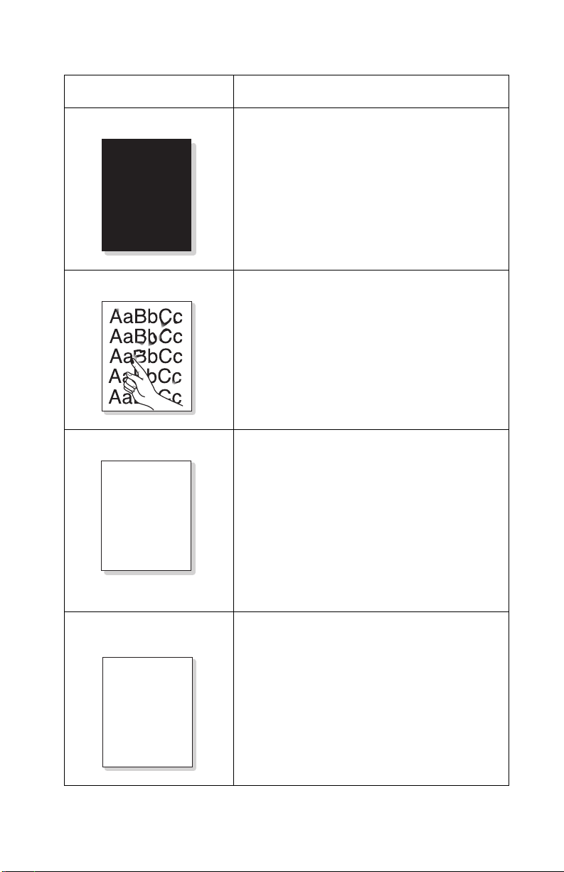
• Straight thin black
vertical line and band
• Dark black vertical
bands
AaBbCc
AaBbCc
AaBbCc
AaBbCc
AaBbCc
• Vertical white streak
• Faded areas
AaBbCc
AaBbCc
AaBbCc
AaBbCc
AaBbCc
• The drum inside the toner cartridge has
probably been scratched.
• Toner cartridge failure.
• Foreign material between transfer/charge/
development rollers.
• Deformed transfer roller.
• The toner supply is low. Before changing
the cartridge, try redistributing the toner or
cleaning the photoconductor drum first.
• Toner cartridge failure.
Note: If dense paper is used or processing
a lot of graphics, the cartridge may need
changing more often.
• Paper may not meet specifications (too
moist or too rough). See “Paper and
speciality media guidelines” on page 1-3
for more information.
• If the entire page is light, adjust the
darkness and content. See “Customizing
settings” on page 3-19 for more
information.
• A combination of faded or smeared defects
may indicate that the toner cartridge needs
cleaning. See “Cleaning the
photoconductor drum” on page 1-9 for
more information.
• Printhead failure.
• Fuser failure.
• Foreign material on printhead lens.
Diagnostic information 2-21
Page 54

4038-001
Problem Possible causes
Dark or blurry horizontal
stripes
AaBbCc
• Check the toner cartridge installation.
• Toner cartridge may be defective.
Toner cartridge failure.
• Bad or dirty voltage contacts.
AaBbCc
AaBbCc
AaBbCc
AaBbCc
Toner smear • Clean inside printer. See “Cleaning the
• Dark or blurry black
spots occur periodically
• White spots occur
periodically
AaBbCc
AaBbCc
AaBbCc
inside of the machine” on page 1-6 for
more information.
• Check paper type and quality. See
“Selecting print materials” on page 1-2
for more information.
• Toner cartridge failure.
• Fuser failure.
• Paper may not meet specifications (too
moist or too rough). See “Paper and
speciality media guidelines” on page 1-3
for more information.
• Check paper path for debris. See
“Cleaning the inside of the machine” on
page 1-6 for more information.
• Toner cartridge failure.
• Transfer roller failure.
AaBbCc
AaBbCc
2-22 Service Manual
Page 55

4038-001
Problem Possible causes
Background scatter • Paper may be damp. Try printing with a
different batch of paper.
Note: Paper does absorb moisture. Open
paper packages when ready for use.
• If background scatter occurs on an
envelope, change printing layout to avoid
A
Misformed characters • Paper stock may be too slick causing
printing over areas with overlapping seams
on the reverse side.
• If background scatter covers the entire
surface area of a printed page, adjust the
print resolution through a software program
or the printer properties.
characters to be improperly formed and
producing hollow images. See “Selecting
print materials” on page 1-2 for more
information.
• Scanner unit may be defective causing
characters to be improperly formed and
producing a wavy effect.
• Inspect the CCD unit for proper operation
and movement.
• Ensure the belt, which moves the CCD unit,
is properly installed.
Page skew • Check paper type and quality. See
“Selecting print materials” on page 1-2
AaBbCc
AaBbCc
AaBbCc
AaBbCc
AaBbCc
for more information.
• Ensure paper or other material is loaded
correctly.
• Ensure the guides are not too tight or too
loose against the paper stack. See
“Selecting print materials” on page 1-2
for more information.
Diagnostic information 2-23
Page 56

4038-001
Problem Possible causes
Curl or wave • Check paper type and quality. See
“Selecting print materials” on page 1-2
for more information.
Note: High temperature and humidity can
cause paper curl.
• Turn over the stack of paper and rotate
180° in the tray.
Wrinkles and creases • Ensure the paper is loaded properly.
• Check the paper type and quality. See
“Selecting print materials” on page 1-2
for more information.
• Turn over the stack of paper and rotate
180° in the tray.
Back of printout is dirty • Clean transfer roller. See “Cleaning the
machine” on page 1-5 for more
information.
• Check for leaking toner. Clean inside the
printer. See “Cleaning the inside of the
machine” on page 1-6 for more
information.
• Fuser failure (dirty).
Printed image is light, with
no residual image
AaBbCc
AaBbCc
AaBbCc
AaBbCc
AaBbCc
2-24 Service Manual
• Toner save mode on.
• Toner cartridge failure.
• Transfer roller failure.
• Bad or dirty voltage contacts.
• HVPS failure.
Page 57
4038-001
Problem Possible causes
Black or dark image • Check that toner cartridge is installed
properly.
• Toner cartridge failure.
• Bad or dirty high voltage contacts.
• HVPS failure.
Loose toner • Clean the inside of the printer. See
“Cleaning the inside of the machine” on
page 1-6 for more information.
• Check paper type and quality. See
“Selecting print materials” on page 1-2
for more information.
• Toner cartridge failure.
• Check that correct media type is selected.
• Fuser failure.
Character voids White areas, within the parts of characters,
that should be solid black.
• If transparencies are used, try another type
of transparency.
• Check that the printing is on the corr ect
surface. Remove the paper and turn over in
A
tray.
• Check that paper meets paper
specifications. See “Selecting print
materials” on page 1-2 for more
information.
Print density is uneven
from left to right
a b cCBA
a b cCBA
a b cCBA
a b cCBA
a b cCBA
• Toner cartridge failure.
• Improper transfer roller installation.
• Transfer roller failure.
Diagnostic information 2-25
Page 58

4038-001
Problem Possible causes
• Background appears in
print area
• Gray background
AaBbCc
AaBbCc
AaBbCc
AaBbCc
AaBbCc
Residual image occurs at
75 mm intervals
AaBbCc
AaBbCc
AaBbCc
75mm
AaBbCc
AaBbCc
Residual image occurs at
75 mm intervals when
printing card stock or
transparencies
• Check for recommended paper weight
(recycled or poor quality paper). See
“Selecting print materials” on page 1-2
for more information.
• Check machine environment.
• Toner cartridge failure.
Note: Very dry (low humidity) or humid
(higher than 80% relative humidity (RH))
conditions can increase background
shading.
• Dirty transfer roll.
• Transfer roll failure or improperly installed.
• HVPS failure.
• Toner cartridge failure.
• Bad or dirty high voltage contacts.
• Transfer roller failure.
• Engine board failure.
Software not set to card stock or transparency
mode.
AaBbCc
AaBbCc
AaBbCc
AaBbCc
AaBbCc
2-26 Service Manual
75mm
Page 59

Problem Possible causes
4038-001
Residual image occurs in
the black image printing at
37 mm intervals
AaBbCc
AaBbCc
AaBbCc
AaBbCc
AaBbCc
AaBbCc
Residual image occurs at
64 mm intervals
37mm
AaBbCc
AaBbCc
AaBbCc
64mm
AaBbCc
AaBbCc
• Toner cartridge failure.
• Bad or dirty high voltage contacts.
• Fuser temperature maintained too high.
Check for toner buildup on hot roller and
thermistor surface.
• Clean or replace fuser if necessary.
Diagnostic information 2-27
Page 60

4038-001
Problem Possible causes
Blank page prints • Redistribute the toner.
• If necessary, replace the toner cartridge.
• Ensure the printed file doesn’t have blank
pages.
• Bad or dirty high voltage contacts; inspect
and clean contacts.
• Replace the LVPS/HVPS.
• Replace the system board.
• Blank page prints
• One or several blank
pages print
• When printer is powered
on, several blank pages
print
• Bad or dirty high voltage contacts.
• Pick roller solenoid failure.
• System board failure.
2-28 Service Manual
Page 61

4038-001
If an abnormal image prints periodically, check the following parts:
No.
Fuser
7
Distance
between
repeated
marks
6
Related
printer
components
2
1
5
Ty pe of
abnormal
image
1 75.5 mm OPC drum White or black
Toner Cartridge
4
3
Replace
Toner cartridge
spots/voids
2 37.7 mm Charge roller Black spots Toner cartridge
3 37.0 mm Supply roller Horizontal shock
Toner cartridge
lines
4 35.2 mm Deve loper
roller
5 45.3 mm Transfer roller Back side
Horizontal shock
lines
Toner cartridge
Transfer roller
contamination
6 64.1 mm Hot roll White or black
Fuser
spots/voids
7 75.5 mm Back-up roller Back side
contamination
Fuser
Diagnostic information 2-29
Page 62

4038-001
Service checks
Cooling fan
FRU Action
Cooling fan,
LVPS/HVPS,
system board
• Perform the “Motor, Fan,
Solenoid test” on page 3-11 to
see if the fan turns on.
• If the fan turns on, the problem is
likely associated with the system
board.
• If the fan does not turn on, make
sure the cooling fan cable is
properly seated in CN3 on the
LVPS/HVPS.
• Disconnect the fan, and check
CN3—1 for +24 V dc.
• If the voltage is present, replace
the cooling fan.
• If the voltage is not present,
replace the LVPS/HVPS.
2-30 Service Manual
Page 63

Main drive motor
FRU Action
4038-001
Main drive motor,
system board,
LVPS/HVPS
• Perform the “Motor, Fan,
Solenoid test” on page 3-11 to
see if the main drive motor turns
on.
• If the motor works but is noisy,
replace the main drive assembly.
• If the motor works correctly in this
test but not during normal printing,
the problem may be associated
with a faulty system board.
• If the motor does not work at all
during this test, make sure the
motor cable is properly
connected.
• If connections are correct and the
problem persists, replace the
main drive assembly.
• If the problem persists, replace
the LVPS/HVPS.
Document cover open switch
FRU Action
Document cover
switch,
operator panel
• First, make sure the document
cover open switch cable is
properly seated in CN1 on the
operator panel.
• Disconnect the cable from CN1 on
the operator panel and check
CN1—1 for +5 V dc.
• If the voltage is present, the
document cover switch is faulty.
• If the voltage is not present,
replace the operator panel.
Diagnostic information 2-31
Page 64

4038-001
Dead machine
FRU Action
Line voltage Check the AC line voltage to make
sure it is correct.
L VPS/HVPS to system
board cable
L VPS/HVPS Check the following voltages on CN2
Ensure the cable connecting the
LVPS/HVPS to the system board is
properly seated.
of the LVPS/HVPS:
•pin 3, +5Vdc
•pin 4, +5Vdc
• pin 5, Ground
• pin 6, Ground
• pin 7, +12 V dc
• pin 8,9,10,11, Ground
• pin 12, +24 V dc
If any of the voltage measurements
are not correct, replace the LVPS/
HVPS.
2-32 Service Manual
Page 65

Operator panel, scanner card assembly
FRU Action
4038-001
Operator panel
scanner card assembly
• Perform the “Operator Panel
test” on page 3-13 to check for
proper operation of the LCD
screen, LED(s) and key buttons.
• If the operator panel does not
work at all, check the following on
the scanner card:
—CN2—1, Ground
—CN2—2, +5 V dc
• If the voltage is not present,
replace the scanner card.
• If the voltage is present, check for
continuity of the operator panel
cable.
• If continuity is missing in any part
of the cable, replace the cable.
• Otherwise, replace the operator
panel.
Diagnostic information 2-33
Page 66

4038-001
2-34 Service Manual
Page 67

3. Diagnostic aids
Configuration modes
Clear All Memory mode
The Clear All Memory setting is used to reset all settings back to
factory defaults.
Note: Page counts are not reset when Clear All Memory is
performed.
To adjust Clear All Memory:
1. Press Menu, #, 1, 9, 3, 4.
The LCD displays TECH.
2. Press Menu, and then Select.
3. Select Data Setup.
4. Select Clear All Memory.
5. Select the country where the machine is located and press
Select to save the setting.
4038-001
6. Press Return to go back to TECH screen.
7. Press Menu, #, 1, 9, 3, 4 to exit TECH mode.
Diagnostic aids 3-1
Page 68

4038-001
Clear Count mode
The Clear Count mode is used to reset the various page counters /
cartridge counters stored in printer NVRAM.
To adjust Clear Counts:
1. Press Menu, #, 1, 9, 3, 4.
The LCD displays TECH.
2. Press Menu, and then Select.
3. Select Data Setup
4. Select Clear Count
5. You are prompted to enter the password. Press 1, 9, 3, 4 and
then Select.
6. The following choices are available and can be reset:
Total Page CNT The page count printed on the current fuser
(Total Pages)
CRU Print CNT The count of cartridges used (Cartridge
Pages)
FL T Sca n CNT The count of pages scanned by the Flatbed
(Platen Pages)
ADF Scan CNT The count of pages scanned by the ADF
(ADF Pages)
Used Toner CNT The number of cartridge changes
Edit Toner Dot The lifetime page count for the printer (T otal
(Cartridge Replacements)
Toner Count
7. Press Return to go back to TECH screen.
8. Press Menu, #, 1, 9, 3, 4 to exit TECH mode.
3-2 Service Manual
Page 69

4038-001
Dial mode
The Dial mode setting allows the modem card to be changed
between pulse or tone dial modes.
To adjust Dial mode:
1. Press Menu, #, 1, 9, 3, 4.
The LCD displays TECH.
2. Press Menu, and then Select.
3. Select Data Setup.
4. Select Dial mode.
5. Use the arrow keys to select the desired dial mode.
6. Press Select to save the setting.
7. Press Return to go back to TECH screen.
8. Press Menu, #, 1, 9, 3, 4 to exit TECH mode.
Error Rate mode
The Error Rate setting is a level used to automatically lower the
modem speed when errors occur. Whenever the error rate exceeds
this setting the baud rate of the modem card automatically drops to
2400 bps.This setting can be set at 5% or 10%.
To adjust the Error Rate:
1. Press Menu, #, 1, 9, 3, 4.
The LCD displays TECH.
2. Press Menu, and then Select.
3. Select Data Setup.
4. Select Error Rate.
5. Select the desired error rate value (5% or 10%) and press
Select to save the setting.
6. Press Return to go back to TECH screen.
7. Press Menu, #, 1, 9, 3, 4 to exit TECH mode.
Diagnostic aids 3-3
Page 70

4038-001
Modem Speed mode
The Modem Speed setting is used to select the modem speed. The
possible choices are:
• 4.8
• 9.6
• 12.0
• 14.4
• 28.8
• 33.6 Kbps.
To adjust the Modem Speed:
1. Press
2. Press Menu, and then Select.
3. Select Data Setup.
4. Select Modem Speed.
5. Select the desired modem speed value and press Select to
6. Press Return to go back to TECH screen.
7. Press Menu, #, 1, 9, 3, 4 to exit TECH mode.
Menu, #, 1, 9, 3, 4.
The LCD displays TECH.
save the setting.
3-4 Service Manual
Page 71

Park CCD module mode
This function parks the CCD module in the middle of the flatbed to
prevent damage to the CCD module during shipping. Perform this
function whenever the printer is to be shipped.
To park the CCD module:
1. Press Menu, #, 1, 9, 3, 4.
The LCD screen displays TECH.
2. Press Menu, and then Select.
3. Select Machine Test.
4. Select Move CCD.
The CCD module parks in the shipping position.
5. At this point, the printer can be powered off and packaged for
shipping.
Note: Once the power is turned back on, the CCD module
returns to a normal position.
6. To return the CCD module without powering off the machine, lift
the document cover and then lower document cover.
4038-001
Diagnostic aids 3-5
Page 72

4038-001
Print Properties mode
Settings to adjust for a print job include:
• Orientation - the direction information is printed on a page.
• 2-UP or 4-UP - multiple pages printed on one sheet.
• Scale - the size information is printed on a page.
• Fit to Page - used to fit a document to a selected paper size.
• Watermark - text printed over an existing document.
• Overlay - specific text or images printed on multiple documents,
such as the text or images that make up a letterhead.
• Odd/Even pages and Manual feed - used to print on both
sides of the paper.
Access Print Properties using the program or the Printers folder.
Note:
• Accessing Print Properties from the program, any settings
changed are in effect only while using the current program.
• Accessing Print Properties from the Printers folder , any settin gs
changed are permanent.
3-6 Service Manual
Page 73

4038-001
Print settings description
From this tab: Change these settings:
Layout Orientation - select how the document is oriented on the
printed page.
Layout - select the type of layout for the document.
Paper Copies - select the number of copies to print.
Type - select the type of paper to use.
Make sure that Type is set to Printer Default. If you load
specialty media, select the corresponding paper type.
For more information see the User’s Guide.
Source - select the paper input source (front input tray or
manual bypass).
The Manual Feed
specialty media. Load one sheet at a time into the
manual bypass.
If the paper source is set to Auto Select, the machine
automatically picks up print materials from the manual
bypass first, and then the paper tray.
Size - select the size of paper to use.
Graphics Resolution - select the quality of the output (600 dots per
inch (dpi) for normal quality or 300 dpi for draft quality).
source is used when printing
Extras Watermark - select the text to print over an existing
document.
Overlay- select a one-page document containing text or
graphics to print over another document.
Diagnostic aids 3-7
Page 74

4038-001
Send Level mode
The Send Level setting adjusts the transmission signal level of the
modem card. Typically, this level should be under 12dB.
Note: The Send Level is set at the factory at an optimal setting. Do
not arbitrarily adjust.
To adjust Send Level:
1. Press Menu, #, 1, 9, 3, 4.
The LCD displays TECH.
2. Press Menu, and then Select.
3. Select Data Setup.
4. Select Send Level.
5. Key in desired send level (9—15) and press Select.
6. Press Return to go back to TECH screen.
7. Press Menu, #, 1, 9, 3, 4 to exit TECH mode.
System Settings Report mode
This function prints a listing of all configuration settings, code
version levels, and page counts.
To print a System Settings report:
1. Press Menu, #, 1, 9, 3, 4.
The LCD screen displays TECH.
2. Press Menu, and then Select.
3. Select Report.
4. Select System Data.
5. A system settings page prints.
6. Press Menu, #, 1, 9, 3, 4 to exit TECH mode.
3-8 Service Manual
Page 75

Machine tests
DRAM Memory test
The DRAM Memory test checks all DRAM memory on the system
board.
To enter the DRAM Memory test:
1. Press Menu, #, 1, 9, 3, 4.
The LCD screen displays TECH.
2. Press Menu, and then Select.
3. Select Machine Test.
4. Select DRAM Test.
The test runs automatically.
— If the test passes, the LCD screen displays OK.
— If the test fails, an error message displays.
Replace the system board if the DRAM Memory test fails.
5. Press Return to exit the test.
6. Press Menu, #, 1, 9, 3, 4 to exit TECH mode.
4038-001
Diagnostic aids 3-9
Page 76

4038-001
Modem Protocol Log test
The Modem Protocol log prints the sequence of the CCITT group 3
T.30 protocol during the most recent sending or receiving operation.
This report is used to check for send and receive errors.
To perform the Modem Protocol log:
1. Press Menu, #, 1, 9, 3, 4.
The LCD screen displays TECH.
2. Press Menu, and then Select.
3. Select Machine Test.
4. Select Report.
5. Select Protocol.
A Modem Protocol log page prints.
6. Press Menu, #, 1, 9, 3, 4 to exit TECH mode.
Modem test
The Modem test causes the modem to send various transmit signals
on the telephone line. The signals are audible through the speaker.
To enter the Modem test:
1. Press Menu, #, 1, 9, 3, 4.
The LCD screen displays TECH.
2. Press Menu, and then Select.
3. Select Machine Test.
4. Select Modem Test.
5. Select the baud rate to test.
6. Press Select to begin the test.
7. Press Return to end the test.
8. Press Stop/Clear twice to exit the test.
9. Press Menu, #, 1, 9, 3, 4 to exit TECH mode.
3-10 Service Manual
Page 77

Motor, Fan, Solenoid test
This test checks the following components:
• Main drive motor
• Paper tray pick—up solenoid
• Cooling fan
• Main feed roller/bypass solenoid
• Pre—transfer LED
To enter the Motor, Fan, Solenoid test:
1. Press Menu, #, 1, 9, 3, 1.
2. Select Diagnostic.
3. Press Select for Mtr Fan Sol.
Each component is listed one at a time. The first component
is the main drive motor.
4. To test the component, press 1.
5. To turn off the component test and proceed to the next
component test, press 2.
4038-001
The test can be exited at any time by pressing Return.
Note: If a component was activated when Return is pressed,
that component remains activated while another test can run
concurrently.
6. Press Stop/Clear to exit the Diagnostic Test mode.
Diagnostic aids 3-1 1
Page 78

4038-001
Operator Panel Button test
The Operator Panel Button test checks all key buttons on the
operator panel.
To enter the Operator Panel Button test:
1. Press Menu, #, 1, 9, 3, 4.
The LCD screen displays TECH.
2. Press Menu, and then Select.
3. Select Machine Test.
4. Select Switch Test.
5. Press the desired key button(s), one at a time, to perform the
test.
As a key button is pressed, the LCD screen displays the name
of the key button.
6. Press Stop/Clear twice to exit the test.
7. Press Menu, #, 1, 9, 3, 4 to exit TECH mode.
3-12 Service Manual
Page 79

Operator Panel test
To perform the Operator Panel test:
1. Press Menu, #, 1, 9, 3, 8.
2. Press, Select
3. Select LCD LED Key.
4. Press any key to begin the LCD test.
— Each pel of the LCD panel is illuminated, starting from left to
right. Once all pels have been illuminated, press any key. All
LEDs now illuminate.
5. Press Menu to perform the LED test.
— The light contrast LED turns off. By continuing to press any
key , ea ch L ED turns off. When the last LED is turned off, the
Key Button test begins.
6. Press each key button prompted by the LCD screen to verify
that each button is working.
Note: If you press a button other than the one prompted, a
series of beeps is audible.
— After each key button has been pressed, the LCD screen
indicates that the test is complete.
— If any of the LCD pels do not illuminate, any of the LEDs do
not illuminate, or any of the key buttons do not work, replace
the operator panel.
4038-001
Diagnostic aids 3-13
Page 80

4038-001
Printhead test
The Printhead test checks the following components:
• Printhead motor
• Printhead HSYNC
• Laser diode
To enter the Printhead test:
1. Press Menu, #, 1, 9, 3, 1.
2. Select Diagnostic.
3. Press Menu, and then select LSU test.
4. Press Select.
Each component is listed one at a time. The first component is
the printhead (LSU) motor.
5. To test the component, press 1.
The LCD screen displays Ready once the component passes
the test.
6. To turn off the component test and proceed to the next
component test press 2.
The test can be exited at any time by pressing Return.
Note: If a component was activated when Return is pressed,
that component remains activated while another test can run
concurrently.
7. Press Stop/Clear to exit the Diagnostic test mode.
3-14 Service Manual
Page 81

4038-001
Print Quality Pages test
This function prints a variety of test pages used to verify print quality .
There are seven different test patterns.
Pattern Description
1 Graphics / image quality
2 Graphics / image quality
3 Horizontal lines
4 White page
5 Dot array (fine)
6 Dot array (coarse)
7 Vertical lines
To perform the Print Quality Pages test:
1. Press Menu, #, 1, 9, 3, 4.
The LCD screen displays TECH.
2. Press Menu, and then Select.
3. Select Machine Test.
4. Select Pattern Test.
5. Select the pattern to print, or select All to print all test patterns.
Select the number of pages to be printed per test at the print no.
prompt.
6. Press Menu, #, 1, 9, 3, 4 to exit TECH mode.
Diagnostic aids 3-15
Page 82

4038-001
ROM Memory test
The ROM Memory test checks the ROM memory in the printer.
To enter the ROM Memory test:
1. Press Menu, #, 1, 9, 3, 4.
The LCD screen displays TECH.
2. Press Menu, and then Select.
3. Select Machine Test.
4. Select ROM Test.
The test runs automatically.
— If the test passes, the flash and engine code levels are
displayed on the LCD screen.
— If the test fails, replace the system board.
5. Press Return to exit the test.
6. Press Menu, #, 1, 9, 3, 4 to exit TECH mode.
3-16 Service Manual
Page 83

4038-001
Scanner CCD Module and Motor test
This test is used to check for proper movement of the CCD module
from one side of the flatbed scanner to the other.
To perform the scanner CCD tests:
1. Press Menu, #, 1, 9, 3, 8.
2. Press the right arrow key to select scanner.
3. Press Select.
4. Press Start to begin the test.
— During this test the CCD module moves continuously from
side to side.
— If the CCD does not move smoothly, or not at all, check that
the belt is properly installed between the motor pulley and
CCD module.
— Ensure the CCD module is installed correctly.
— If the CCD module strikes the left side of the scanner, the
CCD module is not sensing its home position. This can be
caused by a faulty CCD module cable, or the home position
sensor which is part of the CCD module assembly.
5. Press Stop, at any time, to stop the test.
Sensor test
The Sensor test checks the following components:
• Main paper feed/toner cartridge present sensor
• Fuser exit sensor
• Toner cartridge access cover open sensor
• Paper tray empty sensor
• Manual bypass sensor
Diagnostic aids 3-17
Page 84

4038-001
To enter the Sensor test:
1. Press Menu, #, 1, 9, 3, 1.
2. Select Diagnostic.
3. Press Menu, and then select Sensor Test.
4. Press Select.
5. Each sensor is tested one at a time.
The first sensor checked is the main paper feed/toner cartridge
present.
6. Manually actuate the sensor flag while pressing 1 on the
operator panel.
The LCD screen briefly posts On or Off depending on the
position of the sensor actuator when 1 is pressed.
7. Press 2 to move to the next sensor to be tested.
The test can be exited at any time by pressing Return.
Note: If a component was activated when Return is pressed,
that component remains activated while another test can run
concurrently.
8. Press Stop/Clear to exit the Diagnostic test mode.
Note: While the toner cartridge is removed, the main paper feed/
toner cartridge present sensor posts an On message when the
actuator is fully up or down. With the cartridge installed, an Off
message is posted. This sensor detects both paper jams and
cartridge present.
Note: There are two tests on the Lexmark X215 MFP
not used in servicing this printer.
— Heat test
— HVPS test
LCD that are
3-18 Service Manual
Page 85

4038-001
Customizing settings
All the copy options (content, darkness, number, scale, and
advanced) using the operator panel buttons can be temporarily
modified. Settings remain in effect until a predefined time-out period
is expired.
Note:
• Make all of your selections before pressing Start.
• Press Stop/Clear while modifying the copy settings cancels all
settings for the current job and returns them to their default
status.
Content
The content setting is used to improve copy quality . Choose from the
following settings:
•
Text
- use for documents containing mostly text.
•
Mixed
- use for documents with mixed text and graphics.
•
Photo
- use when the originals are photographs.
To select, press Content repeatedly.
Each time you press Content, the LED labeled with the selected
mode lights up.
Note: When you copy a document with color in the background
using the Mixed mode, the machine automatically removes the
background color. If you want to include the background color in
your copy, load the document about 5 mm away from the edges of
the scanning bed, or change the darkness setting.
Diagnostic aids 3-19
Page 86

4038-001
Darkness
The darkness setting is used for an original document containing
paint markings or dark images:
•
Light
- works well with dark print.
•
Normal
- works well with standard typed or printed documents.
• Dark - works well with light print or faint pencil markings.
To adjust the darkness, press Darkness repeatedly.
Each time you press the button, the LED labeled with the selected
mode lights up.
Number
Select number of copies from 1 to 99.
1. Press Number.
2. Enter the number of copies to print using the numeric keypad.
3. Press Select.
The selected number appears on the display.
3-20 Service Manual
Page 87

Scale
Original documents copied from the document glass, can be
reduced or enlarged from 25% to 400%.
Original documents copied from the ADF, can be reduced or
enlarged from 25% to 100%.
To scale a document to a pre—defined copy size:
1. Press Scale.
The default setting appears on the bottom line of the display.
2. Press a scroll button ( ) repeatedly until the copy size is
displayed.
3. Press Select.
To customize the copy size:
1. Press Scale.
2. Press a scroll button ( ) until CUSTOM:25—400% (or
CUSTOM:25—100%) appears on the bottom line of the display.
3. Press Select.
or
or
4038-001
4. Enter the size using the numeric keypad.
5. Press Select.
The selected number appears on the display.
Diagnostic aids 3-21
Page 88

4038-001
Advanced
The advanced option, copies images onto a page in a variety of
layouts.
The advanced settings available when a document is loaded in the
ADF include:
• Off - turns off the advanced copy features.
• Collation - controls the sequence in which multiple page
documents are printed.
• 2—Up - prints two copied documents on a single page.
• 4—Up - prints four copied documents on a single page.
The advanced settings available when a document is loaded in the
scanner bed include:
• Off - turns off the advanced copy features.
• Auto Fit - automatically reduces or enlarges the original image
so the resulting copy fits on the paper.
• 2—Side - prints two copied documents on a single page. When
using the scanner bed, the 2—Side feature is especially useful
when copying both sides of an original document.
Note: Auto Fit and 2—Side can be selected only when the
paper size is letter, legal, or A4.
To select the adva nc ed sett ing :
1. Press Advanced repeatedly until the desired setting appears.
2. Press Select.
3-22 Service Manual
Page 89

4. Repair information
CAUTION: When you see this symbol, there is a
danger from hazardous voltage in the area of the
product where you are working. Unplug the product
before you begin, or use caution if the product mu st
receive power in order to perform the task.
Removals
Covers
Cartridge access cover removal
1. Remove the paper tray.
2. Open the access cover.
4038-001
Repair information 4-1
Page 90

4038-001
3. Press in on one side of the access cover to release it.
4. Release the other side of the access cover and remove.
4-2 Service Manual
Page 91

Middle cover removal
1. Remove the scanner and scanner card assembly. See
“Scanner assembly removal” on page 4-64, and “Scanner
card assembly removal” on page 4-68 for more information.
2. Slip the cables out of the middle cover (A) (scanner to system
board).
4038-001
3. Remove six screws (A) in the middle cover.
Repair information 4-3
Page 92

4038-001
4. From the front of the printer, pull both the middle cover legs
away from the printer to release tabs.
5. Lift up to remove the middle cover.
4-4 Service Manual
Page 93

Rear cover removal
1.Remove four screws (A).
4038-001
Repair information 4-5
Page 94

4038-001
2. Pull the rear cover to remove.
4-6 Service Manual
Page 95

Scanner assembly document cover removal
1. Remove the left side cover. See “Left side” on page 4-12 for
more information.
2. Remove the ground screw on the drive assembly. See
“Scanner assembly removal” on page 4-64 for more
information.
3. Disconnect the scanner assembly cable (A) (CN3).
4038-001
Repair information 4-7
Page 96

4038-001
4. Un—thread the cable (A) from the scan ne r do cu m en t cov er.
4-8 Service Manual
Page 97

5. Open the document cover.
4038-001
Repair information 4-9
Page 98

4038-001
6. Lift the document cover until the hinges catch (A).
4-10 Service Manual
Page 99

7. Tilt back and lift off the scanner document cover.
4038-001
Repair information 4-11
Page 100

4038-001
Side cover removals
Left side
1. Remove the rear cover. See “Rear cover removal” on
page 4-5 for more information.
2. Disconnect the speaker cable (A).
4-12 Service Manual
A
 Loading...