

Page 1

MPX 1 V1.10
MIDI Implementation Details
Page 2

© 1998, Lexicon, Inc.
All Rights Reserved
Lexicon, Inc. • 3 Oak Park • Bedford MA 01730-1441 • Tel: 781 280-0300 • Fax: 781 280-0490
Lexicon Part No. 070-11835 Rev 1
Printed in U.S.A.
Page 3

Contents
Overview ..................................................................1
Data Formatting....................................................1
Message Tables ...................................................2
System Control .....................................................3
Parameter Types.............................................3
Messages........................................................4
Request •System Configuration
Parameter Description • Parameter
Type • Data Transfer
“Learning” the MPX 1 ...........................................4
Building a Parameter Description
Database...................................................4
Building the Control Tree ................................5
Using the Information ...........................................7
An MRC-type Controller ..................................7
A Glass Interface Controller ............................9
Device Inquiry..........................................................9
Message Classes ..................................................10
00 System Configuration Message.....................10
Number of Parameter Types.........................11
Bottom Parameters .......................................11
01 Parameter Data Message..............................11
02 Parameter Display Message .........................13
03 Parameter Type Message .............................14
04 Parameter Description...................................15
Parameter Type Number...............................15
Number of Parameter Name Characters ......15
Parameter Name...........................................16
Number of Bytes ...........................................16
Control Flags.................................................16
Options Parameter Type ...............................16
Number of Units/Limits..................................16
Minimum Value .............................................16
Maximum Value ............................................16
Display Units Type ........................................17
Requesting the Parameter Description .........17
05 Parameter Label Message ............................17
06 Requests .......................................................18
12 Handshaking..................................................19
16 Database Dump.............................................20
18 Report Effect Parameters ..............................21
19 Report All Effect Parameters .........................22
1A Program Information .....................................23
1B Program Dump..............................................24
Parameter Data.............................................26
LFOs through Envelopes ..............................28
Sort Flags......................................................28
Audio Routing................................................29
Rules.......................................................31
Algorithm Numbers .......................................32
Program Name..............................................32
Effect Status..................................................33
Knob Data .....................................................33
Patch System Data .......................................33
Soft Values....................................................35
Tempo ...........................................................35
Tempo Source...............................................36
Beat Value.....................................................36
Tap Source....................................................36
Tap Average..................................................36
Tap Source Level ..........................................36
Meter .............................................................36
Master Level..................................................37
Master Mix.....................................................37
Requesting a Program Dump........................37
1C Compact Program.........................................37
Parameters.............................................................37
Unique Parameters.............................................37
MIDI Speed ...................................................37
Panel Button Message ..................................37
Rate...............................................................38
Dumps ................................................................39
All LEDs Dump ...................................................39
Display Dump .....................................................41
Custom Character Bitmap Dump........................41
Setup Dump........................................................42
Global Patches Dump.........................................45
Bypass Controllers Dump...................................46
Remap Controllers Dump ...................................46
Current Choices Dump .......................................47
Patches Dump ....................................................51
Soft Row Dump ..................................................51
Units ................................................................52
Appendix A: Controller Indeces ..........................53
Master List of Controllers....................................54
Global Patch Controllers.....................................54
Bypass Controllers .............................................55
Appendix B: Display Units ...................................56
Appendix C: Glossary of Terms ..........................57
Appendix D: Known Bugs ....................................58
Page 4
Lexicon
MPX 1 V1.10 MIDI Implementation Details
MPX 1
MIDI Implementation Details
ASCII text versions of this document , the MPX 1 Control Tree and MPX 1 Parameter Descriptions are
available on CompuServe under section seven of the MIDI B forum. To access these documents:
• Enter CompuServe, type GO MIDIBVEN
• Select "section seven: Lexicon"
• Enter the Lexicon library
Overview
This document defines the System Exclusive (SysEx) MIDI implementation used in the Lexicon MPX 1,
and assumes familiarity with the functions and operations of the MPX 1. This document covers both V1.00
and V1.10 software, which was released to support the MPX R1 MIDI Remote Controller.
Data Formatting
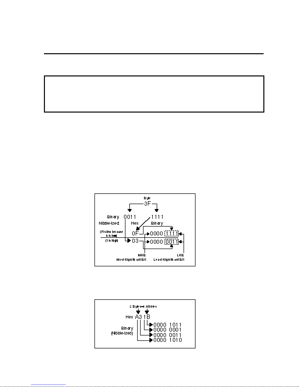
With the exception of message headers (first 5 bytes) and “end of SysEx” messages (the last byte in the
message), all data is transmitted in a nibble-ized format, i.e. each byte of data is transmitted as a pair of
bytes, with 4 bits of data in each byte.
As in all other cases in the MPX 1, the less-significant portion of the byte is transmitted first. 16-bit "words"
(2 bytes) are sent low nibble of the low byte, followed by high nibble of the low byte, low nibble of the high
byte, then high nibble of the high byte.
1
Page 5

LexiconMPX 1 V1.10 MIDI Implementation Details
Message Tables
Throughout this document, SysEx messages are shown as Message Tables to provide a consistent
method of describing the contents of each message class. The tables are organized into rows of related
groups of bytes and columns containing the attributes of each field. For example, the System Configuration message table is defined as follows:
Transmit only
Byte # Byte Value Description Notes
1 F0 Sysex ID (Start)
2 06 Lexicon ID
3 09 MPX 1 ID
4 0bbb bbbb Device ID 0-127
5 00 System Configuration
6-7 0n Major Version (1 byte) The number that appears to the left of the decimal point on
8-9 0n Minor Version (1 byte)
The first column indicates the Byte # of a particular field.
The second column indicates the byte value. This value is generally presented in hex, but may also appear
in binary. In some cases the value is a fixed number (for example: Lexicon ID) while others may vary.
Values that can change are represented using a combination of numbers and letters. Binary numbers,
for instance, are represented using a lower case “b” for each variable bit in the value (for example: Device
ID: 0bbb bbbb). The “b”s can represent 1s or 0s. Hex numbers which can use different numbers in the
lower nibble are represented by a lower case “n” which can represent any hex number between 0 and F.
the power up display. Example: V1.00
Although only a single “0n” is indicated in the Value column for certain fields, these fields will often consist
of multiple bytes (each of which uses the format: 0n). This is due to nibble-ization, and to the fact that a
single field can describe a group of more than 1 byte (strings, for example). In these cases, the Description
column will generally indicate the number of bytes of un-nibble-ized data contained in the field.
2
Page 6

Lexicon
MPX 1 V1.10 MIDI Implementation Details
System Control
All external control is performed using parameters. These parameters are broken down into a two
dimensional inverted tree not unlike the directory structure of a computer disk. Each controllable
parameter in the system (as well as the system itself) is assigned a specific Control Address that defines
its position in the tree. Each System Control Address is defined by a series of Control Levels. The size
(number of control levels) of a given parameter’s Control Address varies depending on its position. The
following diagram shows a portion of the MPX 1 tree with one full branch. (Letters are used to define
System Control levels.)
The parameter which defines the product itself sits at the top of the tree with, essentially, a null control
address (no control levels).
Control levels ->
MPX 1
A B C D E F G H I
| | | | | | | | |
0 - Program
0 - Pitch
0 - Detune (M)
0 - Mix
0-100%
1 - Level
2 - Tune
...
1 - Chorus
0 - Chorus Algorithm
0 - Mix
1 - Level
2 - EQ
...
1 - System
0 - Audio Config
1 - Setup
...
The address of “Program” is A:0, while the address of Detune is A:0, B:0, C:0. Detune’s “Level” is A:0,
B:0, C:0, D:1 and Detune’s “Tune” is A:0, B:0, C:0, D:2. The address of the Chorus Algorithm’s “Level”
is A:0, B:1, C:0, D:1 while “Audio Config” would be at A:1, B:0. The number of control levels increases as
you move to the right in the tree. Each control address in the system that contains a parameter is refered
to as a “node”.
Note that the Control Address is used to identify a specific parameter — including the MPX 1 itself. The
"parameter" which defines the MPX 1 is at the top of the tree with a null Control Address (no control levels).
Parameter Types
MPX 1 system software contains an indexed list of parameter types representing each unique parameter
in the system. The parameter type defines all attributes of the parameter (name, number of bytes, etc.)
except its position in the tree which is defined by its Control Address. Several parameters can be defined
as the same parameter type. For example, each Mix parameter in each algorithm in the MPX 1 is the same
parameter type, but has a different Control Address. Conversely, all System Control Addresses which are
accessible have a single parameter type assigned to them.
3
Page 7

LexiconMPX 1 V1.10 MIDI Implementation Details
Messages
Using Control Addresses and Parameter Types, several SysEx messages have been defined to allow an
external system to learn to control and interface with another MPX 1. Five core messages are typically
used:
Request
System Configuration
Parameter Description
Parameter Type
Data Transfer
These five messages make up a basic toolkit for communicating with the MPX 1. Each message type is
given an identifying number.
Request
The Request message consitutes an external request made to an MPX 1 to respond with one of the other
message types. The Request consists of the identifying number of the message you want returned and,
any specific information the system requires to respond properly.
System Configuration Message
This message provides basic information about the target system such as software revision, date of
release and number of parameter types supported by the particular system.
Parameter Description Message
Each parameter type in the MPX 1 has a “description” that provides information about the parameter such
as its legal values. A controlling system typically “requests” the System Configuration Message to find out
how many parameter types the system supports, then requests the Parameter Description for each
parameter. A local database of parameter descriptions in the controlling system is used to build the control
tree and to edit parameters.
Parameter Type Message
After a database of parameter descriptions has been built of all parameter types, the controlling system
needs to find out what the control tree for the MPX 1 looks like and what parameter type is used at each
“node” of the tree. To do this, the controlling system “requests” the Parameter Type for a specific Control
Address.
Data Transfer Message
After the parameter type at a given control address is known, the Data Transfer Message is used to send
parameter change values to the MPX 1 or to “request” the current value. The Parameter Description tells
you the name and legal values of the parameter.
“Learning” the MPX 1
In order for a controlling system to control or interface with the MPX 1, it needs information such as the
Manufacturer ID, the Product ID and the Device ID of the system. The Manufacturer ID and the Product
ID can be acquired using the Non Real-Time System Exclusive General Information Device Inquiry. The
Device ID can be obtained from the system’s user interface or by using “all devices” (127).
Building a “Parameter Description” Database
Building a control tree and editing parameters requires information about parameter types. The external
control system requests the “System Configuration Message” to tell it how many “types” the system
supports, then requests a description of each parameter. As each parameter description comes in, the
control system builds a database with them. Refer to the Parameter Description (04 hex) for additional
information about the elements of this database.
4
Page 8

Lexicon
MPX 1 V1.10 MIDI Implementation Details
Building the Control Tree
Once the controlling system knows the number of parameters types the system supports, it needs to know
the position of each in the control tree. The Parameter Type message is used to find the location in the
tree of any parameter type. When you want to find out what parameter type is at a particular control
address, you “request” the Parameter Type Message using the Control Address as arguments to the
Request message. The request for a typical Control Address is shown below. Note that the “Num Control
Levels” and the actual Control Address (eg - “Level A value”) fields are 16-bit values in a nibble-ized form
with the least significant nibble coming first.
request
Num Control Level A Level B
——header—— class levels value value
F0 06 09 00 06 03 00 02 00 00 00 00 00 00 00 01 00 00 00 F7
“06” is the message class for the request (un-nibble-ized), “03” is the message class you are requesting
(Parameter Type Message), “2” is the number of control levels in the Control Address, “0” is the value of
level ‘A’ of the Control Address and “1” is the value of level ‘B’ of the Control Address (or A:0, B:1). This
would be “Chorus” in the following tree fragment:
Control levels ->
MPX 1
A B C D E F G H I
| | | | | | | | |
0 - Program
0 - Pitch
0 - Detune (M)
0 - Mix
0-100%
1 - Level
2 - Tune
...
1 - Chorus
0 - Chorus Algorithm
0 - Mix
1 - Level
2 - EQ
...
1 - System
0 - Audio Config
1 - Setup
...
The top of the control tree is a sort of “null” Control Address which doesn’t contain any control levels. It
is requested as follows:
request
Num Control
——header—— class levels
F0 06 09 00 06 03 00 00 00 00 00 F7
The message indicates 0 control levels but the MPX 1 responds with the parameter type at the top of the
tree. The parameter types are represented as numbers in the Parameter Type Message which comes
back from the MPX 1. This number (0x0155) is then used as an index into the database of parameter
descriptions created earlier. Building the control tree always starts by requesting the parameter type at
the top of the tree.
5
Page 9

LexiconMPX 1 V1.10 MIDI Implementation Details
Once you have access to the description of the parameter at the top of the control tree, the description
contents is used to build the tree below it. Each of the descriptions contains a “min” value and a “max”
value. For parameters such as “Mix” that can be edited, these are the maximum mix value (100) and the
minimum mix value (0) to which the parameter can be set. When the parameter type is not an editable
parameter, the min and max represent the tree branches below it. A parameter is considered editable if
the “Control Level” flag in the parameter description Control Flags field is NOT set (see Parameter
Description (04 hex). For these parameter types the min value is always 0 and the max value is always
the number of branches below it, minus 1. The min and max values represent the minimum and maximum
branch (level value) that can be accessed below it. In the case of the top level parameter, the max value
is the largest level ‘A’ Control Address value allowed.
When the controlling system knows how many level ‘A’ parameters are allowed, it can work with those
branches. In the MPX 1, it the max value under the top level parameter type is 1. This means that level
“A” can be 0 or 1. The controller would then request the parameter “type” at control address A:0 (A = 0)
as follows:
request
Num Control
——header—— class levels level A
F0 06 09 00 06 03 00 01 00 00 00 00 00 00 00 F7
The MPX 1 would send back the parameter type at that Control Address (0x0153, the “Program”
parameter). In the MPX 1, this parameter has a max value of 19. This means that control addresses A:0
B:0 through A:0 B:19 are legal so you can request parameter types for these addresses. In the next
request you would go one level deeper:
request
Num Control
——header—— class levels level A level B
F0 06 09 00 06 03 00 02 00 00 00 00 00 00 00 00 00 00 00 F7
The MPX 1 system would send back the parameter type at that control address (0x014D, the “Pitch”
parameter). In the MPX 1, this parameter has a max value of 10. This means that control addresses A:0
B:0 C:0 through A:0 B:0 C:10 are legal so you can request parameter types for these addresses.
This continues deeper and deeper into the control levels (letters) until you reach an actual editable
parameter. At this point you have reached the end of the branch so you go to the next value of that level.
In the MPX 1, the entire first branch looks like this:
Control level
A B C D E F G H I
MPX 1
| | | | | | | | |
0 - Program
0 - Pitch
0 - no effect
0 - Mix
6
Page 10

Lexicon
MPX 1 V1.10 MIDI Implementation Details
When you hit the “Mix” parameter, you are at the end of the branch so you would go to the next address
under “no effect” which is “Level”.
Control level
A B C D E F G H I
MPX 1
| | | | | | | | |
0 - Program
0 - Pitch
0 - no effect
0 - Mix
1 - Level
The “no effect” parameter has a maximum value of 1 so you would back up to the next value of
“Pitch” which is “Detune (M)” (A:0, B:0, C:1).
Control level
A B C D E F G H I
MPX 1
| | | | | | | | |
0 - Program
0 - Pitch
0 - no effect
1 - Detune (M)
The description shows a maximum value of 3, meaning that control addresses A:0 B:0 C:1 D:0 through
A:0 B:0 C:1 D:2 are legal. This procedure continues until you hit the bottom of the tree.
In each parameter’s description, there is a field called “control flags”. This is a bit-mapped value that,
among other things, tells you if a parameter is a “branch” or an editable parameter. If the control flag is
set to 1, there are more parameters beneath it. If the bit is set to 0, the parameter is editable and there
are no parameters beneath it.
Note that all of the numbers in these requests except the message class must be 16-bit values so they
must each be sent as 4 nibble-ized bytes.
Using the information
In many ways, the implementation of MPX 1 SysEx will differ depending on the system in which it is
implemented. A personal computer, for instance, can present more information at one time to the user
than a hand held remote control. The personal computer also has a much larger memory capacity (for
holding onto databases, etc.) than the remote. On the other hand, a program running on a personal
computer may not want to tie up memory with information about connected equipment or provide more
than a simple interface to the box. All of these issues effect how a particular program will use LUSP to
control a system.
Please note that these are hypothetical implementations only.
An MRC-type of Controller
A simple implementation on a system like the Lexicon MRC would not have enough internal memory
to hold much information about the connected system at any given time so it would have to request
information of the system as needed.
The MRC only has 4 faders so only 4 parameters could be accessed at any given time. The faders
and their associated buttons would either allow you to navigate through the control tree or actually
change a parameter value. The MACH button on the MRC could be designated as an <Esc> key to
back you up towards the top of the tree while the faders and buttons drop you down into the tree
(fader selects the branch, button drops you down in).
7
Page 11

For example, for the MPX 1, part of the tree looks like this:
System Control level
A B C D E F G H I
| | | | | | | | |
0 - Program
0 - Pitch
0 - Detune (M)
0 - Mix
1 - Level
2 - Tune
3 - P Dly
1 - Detune (S)
...
2 - Detune (D)
...
3 - Shift (M)
...
1 - Chorus
...
2 - EQ
...
3 - Modulation
...
4 - Reverb
...
5 - Delay
...
LexiconMPX 1 V1.10 MIDI Implementation Details
Initially, the MRC display would simply show the name of the connected product which it retrieves by
requesting the Parameter Type at the top of the tree. Once the Parameter Type is known, a request is sent
for a description of the parameter which would include the name of the parameter (in this case “MPX 1”,
the top level parameter). The description also includes a minimum and maximum value for the parameter
which would be used to select branches to drop down into.
This currently has a maximum value of 1 so requests are made for the Parameter Types at System Control
Addresses 0 and 1. Requests are sent for descriptions of the two Parameter Types. The name strings in
the returning messages are used to display the choices, one over each fader: “Program” and “System”.
When a labeled fader is moved, the MRC isends a Parameter Data Message to the connected system
followed by a request for the Parameter Display Message for the parameter. This produces a formatted,
text version of the current parameter value. Pressing the button drops you to the next level. In this example,
let’s assume we’ve selected the “Program” branch. In the above diagram “Program” has 6 items under
it: Pitch, Chorus, EQ, Modulation, Reverb and Delay. Moving the “Program” fader we would see “Pitch”,
“Chorus”, “EQ”, “Modulation”, “Reverb” or “Delay” displayed. The strings would be acquired by setting the
“Program” parameter value and requesting a Parameter Display message.
If the “Program” button is pressed, the system requests the Parameter types of the first four branches
under “Program”: “Pitch”, “Chorus”, “EQ” and “Modulation”. The names from each description are
displayed over the four faders. Pressing the MRC’s PAGE button would get the next four items if available,
eventually wrapping back around to the first four. As the faders are moved, the Parameter Data Message
is sent and Parameter Display message is requested to display the selection.
The previous process is repeated until the “Branch” bit of the “Control Flags” of a parameter description
is encountered set for 0. (Parameters with that bit set to 0 actually change the operation of the system and
signal the end of a branch. The previous parameters only provide navigation through the tree.)
8
Page 12

Lexicon
MPX 1 V1.10 MIDI Implementation Details
A Glass Interface Controller
A glass interface (personal computer, etc.) could take a slightly different approach. With a graphic display
capability and memory (both program and data) to spare, a glass interface can provide more direct and
visually stimulating access to the MPX 1. The glass interface has the option of deriving the tree structure
from the MPX 1 during an initialization phase or of learning the tree structure once then hard (or semi-hard)
coding the Control Addresses to the glass interface elements. The tree structure could still be learned via
MIDI but it would only be used to build a road map into the tree.
Because all aspects of the interface use a common SysEx message (Parameter Data Message), the glass
interface programmer can concentrate on presentation and organization of the information instead of
merely accessing it. Communication traffic could be reduced by doing a one-time build of a parameter
description database.
As a side note, the user interface software in the MPX 1 uses both hard and soft coded Control Addresses
to edit parameters within the box itself.
Device Inquiry
The MPX 1 supports Non-Real Time System Exclusive General Information “Device Inquiry” as defined
in the “MIDI 1.0 Detailed Specification 4.2”. When the MPX 1 receives the following message: F0 7E
<channel> 06 01 F7 (where <channel> is the device ID of the connected MPX 1), the MPX 1 will respond
with the following message:
0xF0, 0xFE <channel> Universal System Exclusive Non-real time header
0x06 General Information (sub-ID#1)
0x02 Identity Reply (sub-ID#1)
0x06 Lexicon’s System Exclusive ID code
0x00, 0x00 Device Family Code
0x09, 0x00 Device Family Member Code (MPX1)
0x0n Major Software Version number
0x0n Minor Software Version number
0x0n Software Development Phase
0x00 unused
0xF7 EOX
9
Page 13

LexiconMPX 1 V1.10 MIDI Implementation Details
Message Classes
MPX 1 System Exclusive uses message types defined as Message Classes. The Message Class
identifier appears just after the standard SysEx header (Start of SysEx: F0, Company ID, Product ID,
Device ID) and defines how the remaining data should be interpreted. The following message classes
have been defined for the MPX 1:
# Hex Description
00 System Configuration Message
01 Parameter Data
02 Parameter Display
03 Parameter Type
04 Parameter Description
05 Parameter Label
06 Requests
12 Handshake
16 Database Dump
18 Effect Parameters
19 All Effect Parameters
1A Program Stats
1B Program Dump
1C Compact (Preset) Program Dump
00 System Configuration Message
The System Configuration Message provides a method for extracting information about the software in
the system from the box via SysEx. As such, this message can only be requested from the system and
will be ignored if sent to the system.
Transmit only
Byte # Value HEX Description Notes
1 F0 Sysex ID (Start)
2 06 Lexicon ID
3 09 MPX 1 ID
4 0bbb bbbb Device ID 0-127
5 00 System Configuration
6-7 0n Major Version (1 byte) The number that appears to the left of the decimal
8-9 0n Minor Version (1 byte) The number that appears to the right of the decimal
10-25 0n 8-character Time string (8 bytes) Time of the code build in ASCII format: xx:yy:zz
26-47 0n 11-character Date string (11 bytes) Date of the code build in ASCII format: xxx:yy:zzzz
48-51 0x01C0 #of parameter types (2 bytes) Total number of parameter types in the MPX 1.
52-55 0x0164 “Bottom” parameter # (2 bytes) Last system control parameter in a branch before
56-59 0x0005 #of Control Levels used (2 bytes) Maximum number of control levels used by the
60 F7 End of Sysex
point on the power up display. Example: V1.00
point on power up display. Example: V1.00
xx = Hour
yy = Minute
zz = Second
Example: 17:51:03
xxx = Month
yy = Day
zzzz = Year
Example: May 10 1996
an editable parameter.
system
10
Page 14

Lexicon
MPX 1 V1.10 MIDI Implementation Details
Number of Parameter Types
The Number of Parameter Types message specifies the number of parameter types in the MPX 1. An
editor program can use this to request Parameter Description (04 hex) dumps of all the parameters in the
system.
Bottom Parameters
A Bottom parameter is the last control level on a given branch and indicates that there is only one lower
level — the one which contains the real, adjustable parameters. With the exception of Effect control levels,
all other parameters are used only to navigate the user interface. (Effect control levels can be sent values
to change the currently running algorithm.)
Rather than identifying Bottom parameters, a controlling system can simply monitor the Control Level flag
in the Parameter Description to identify the end of a branch ( bit/flag cleared).
The remaining information can be used by the controlling system to detect software updates and to
ascertain the ROM version.
There are no arguments to the System Configuration Request. The Request message is as follows
(assuming the Device ID is 0):
Req
——header—— Class ——unused———
F0 06 09 00 06 00 00 00 00 00 00 00 00 F7
|
Device ID (0-126)
01 Parameter Data Message
This message allows all types of parameter data to be passed to and from the system. Typically this
message class is used to change parameter values in a system remotely (automation, etc) and to dump
data in and out of the box. The word “parameter” should be interpreted loosely here as MPX 1 parameters
can be actual dumps as well as traditional parameters such as mix, reverb time, etc.
Transmit + Receive only
Byte # Value HEX Description Notes
1 F0 Sysex ID (Start)
2 06 Lexicon ID
3 09 MPX 1 ID
4 0bbb bbbb Device ID 0-127 transmit, 0-126 receive
5 01 Message class Parameter data
6-9 0n Number of bytes (2 bytes) Number of bytes in the parameter and its option, if available.
10-x 0n Parameter data Actual parameter data and, if available, option data. Option
— 0n # of control levels (2 bytes) Number of control levels are used in the parameter ad-
— 0n Control level 0 (A) (2 bytes) This is the first control level. It defines the level 0 (A) control
— 0n Control level 1 (B) (2 bytes) same as previous
— 0n Control level 2 (C) (2 bytes) same as previous
— 0n — up to Control level 65535 same as previous
F7 End of Sysex
This is a 16-bit field so up to 64K bytes is supported.
data always appears after the parameter data. Use the
number of bytes field of the parameter and the option
description to differntiate the parameter from the option.
dress. This is a 16-bit field so the address can have up to
64k digits (control levels). (MPX 1 max is 5.)
address of the parameter. The control level addresses are
16 bit fields so the control addresses can be 64k deep. Note
that letters are used to differentiate levels and their values.
11
Page 15

LexiconMPX 1 V1.10 MIDI Implementation Details
Note that the “data” includes any Option data associated with the parameter. For example a 16-bit
parameter with an 8-bit option would contain 3 bytes of data. The Parameter Type of both the parameter
and its option must be used to correctly interpret the “data” in this message.
Control Levels are used in the request message for this packet as follows:
0n Number of Control Levels (lo nib) (Nibble 1 of argument)
0n Number of Control Levels (lo mid nib) (Nibble 2 of argument)
0n Number of Control Levels (hi mid nib) (Nibble 3 of argument)
0n Number of Control Levels (hi nib) (Nibble 4 of argument)
0n Control Level 0 (A) (lo nib) (Nibble 5 of argument)
0n Control Level A (lo mid nib) (Nibble 6 of argument)
0n Control Level A (hi mid nib) (Nibble 7 of argument)
0n Control Level A (hi nib) (Nibble 8 of argument)
0n Control Level 1 (B) (lo nib) (Nibble 9 of argument)
0n Control Level (lo mid nib) (Nibble 10 of argument)
0n Control Level (hi mid nib) (Nibble 11 of argument)
0n Control Level B (hi nib) (Nibble 12 of argument)
To request Program - EQ - 1 Band (M) - Gain (control address A:0, B:2, C:1, D:2) on a system with the
Device ID set for 0, send:
request Num Control
——header—— class levels
F0 06 09 00 06 01 00 04 00 00 00
Level A Level B Level C Level D
(Program) (EQ) (1 Band (M)) Gain)
00 00 00 00 02 00 00 00 01 00 00 00 02 00 00 00 F7
A typical return message is as follows:
Number of Number of Control
——header—— data bytes data levels
F0 06 09 00 01 01 00 00 00 00 00 04 00 00 00
Level A Level B Level C Level D
00 00 00 00 02 00 00 00 01 00 00 00 02 00 00 00 F7
To request a display dump (control address A:1, B:8, C:1) on a system with the Device ID set for 0, send:
request Num Control Level A
——header—— class levels (System)
F0 06 09 00 06 01 00 03 00 00 00 01 00 00 00
Level B Level C
(Panel) (Display)
08 00 00 00 01 00 00 00 F7
A typical return message is as follows:
Number of
——header—— data bytes data—>
F0 06 09 00 01 00 02 00 00 00 02 02 05 06 07 02 06 00 00
data—>
0D 04 09 06 08 07 00 02 00 02 00 02 0C 04 05 06 06 07
05 06 0C 06 0C 03 0E 03 00 02 00 02 00 02 00 02 00 02
00 02 00 02 05 0200 02 00 02 00 02 00 03 04 06 02 04
# control lvls Level A Level B Level C
03 00 00 00 01 00 00 00 08 00 00 00 01 00 00 00 F7
12
Page 16

Lexicon
MPX 1 V1.10 MIDI Implementation Details
02 Parameter Display Message
This message allows you to display parameter values based on what they actually do instead of the
numbers that represent them in the stored data structures. This is particularly useful for system
parameters which generally have text strings stored in the internal ROM to describe the values.
Transmit only
Byte # Value HEX Description Notes
1 F0 Sysex ID (Start)
2 06 Lexicon ID
3 09 MPX 1 ID
4 0bbb bbbb Device ID 0-127
5 02 Parameter Display Message class
6-9 0n # of characters (2 bytes) Number of characterss (bytes) in the string
10-x 0n String characters “Number of characters” of nibble-ized ASCII characters
— 0n # of control levels (2 bytes) Number of control levels are used in the parameter ad-
— 0n Control level 0 (A) (2 bytes) This is the first control level. It defines the level 0 (A) control
— 0n Control level 1 (B) (2 bytes) same as previous
— 0n Control level 2 (C) (2 bytes) same as previous
— 0n — up to Control level 65535 same as previous
F7 End of Sysex
dress. This is a 16-bit field so the address can have up to
64k digits (control levels)
address of the parameter. The control level addresses are
16-bit fields so the control addresses can be 64k deep.
Letters are used to differentiate levels and their values.
Control Levels are used in the request message for this packet as follows:
0n Number of Control Levels (lo nib) (Nibble 1 of argument)
0n Number of Control Levels lo mid nib) (Nibble 2 of argument)
0n Number of Control Levels (hi mid nib) (Nibble 3 of argument)
0n Number of Control Levels (hi nib) (Nibble 4 of argument)
0n Control Level 0 (A) (lo nib) (Nibble 5 of argument)
0n Control Level A (lo mid nib) (Nibble 6 of argument)
0n Control Level A (hi mid nib) (Nibble 7 of argument)
0n Control Level A (hi nib) (Nibble 8 of argument)
0n Control Level 1 (B) (lo nib) (Nibble 9 of argument)
0n Control Level B (lo mid nib) (Nibble 10 of argument)
0n Control Level B (hi mid nib) (Nibble 11 of argument)
0n Control Level B (hi nib) (Nibble 12 of argument)
To request Program - EQ - 1 Band (M) - Gain (control address A:0, B:2, C:1, D:2) on a system with the
Device ID set for 0, send:
request Num Control Level A
——header—— class levels (Program)
F0 06 09 00 06 02 00 04 00 00 00 00 00 00 00
Level B Level C Level D
(EQ) (1 Band (M)) (Gain)
02 00 00 00 01 00 00 00 02 00 00 00 F7
The number of characters varies with Parameter Type, the arguments and the actual value of the
parameter.
13
Page 17

LexiconMPX 1 V1.10 MIDI Implementation Details
03 Parameter Type Message
This message is transmitted from the system in response to a request for Parameter Type at a specific
Control Address. This allows external equipment to build a control tree of the system by requesting the
parameter at an address, checking its description to identify it as a Control Level or an adjustable
parameter. (Control Levels indicate at least one lower level.)
Transmit only
Byte # Value HEX Description Notes
1 F0 Sysex ID (Start)
2 06 Lexicon ID
3 09 MPX 1 ID
4 0bbb bbbb Device ID 0-127
5 03 Message Class Parameter Type
6-9 0n Parameter Type (2 bytes) 0x0000-0x01BF (see list)
10 F7 End of Sysex
Control Levels are used in the request message for this packet as follows:
0n Number of Control Levels (lo nib) (Nibble 1 of argument)
0n Number of Control Levels (lo mid nib) (Nibble 2 of argument)
0n Number of Control Levels (hi mid nib) (Nibble 3 of argument)
0n Number of Control Levels (hi nib) (Nibble 4 of argument)
0n Control Level A (lo nib) (Nibble 5 of argument)
0n Control Level A (lo mid nib) (Nibble 6 of argument)
0n Control Level A (hi mid nib) (Nibble 7 of argument)
0n Control Level A (hi nib) (Nibble 8 of argument)
0n Control Level B (lo nib) (Nibble 9 of argument)
0n Control Level B (lo mid nib) (Nibble 10 of argument)
0n Control Level B (hi mid nib) (Nibble 11 of argument)
0n Control Level B (hi nib) (Nibble 12 of argument)
To request the Parameter Type number for Program - EQ - 1 Band (M) - Gain ) on a system with the Device
ID set for 0, send:
request Num Control Level A
——header—— class levels (Program)
F0 06 09 00 06 03 00 04 00 00 00 00 00 00 00
Level B Level C Level D
(EQ) (1 Band (M)) (Gain)
02 00 00 00 01 00 00 00 02 00 00 00 F7
14
Page 18

Lexicon
MPX 1 V1.10 MIDI Implementation Details
04 Parameter Description
Each parameter type used by the system is assigned a unique identifying number, much like menus and
dialog boxes are assigned IDs in Windows and Macintosh software. As these numbers represent the
attributes of a parameter, each can be used for several parameters. An example of this is the audio Mix
parameter type used in all MPX 1 algorithms. The Mix parameter itself is different for each algorithm, but
as each uses the same parameter type, only one parameter description is necessary.
Typically, this message is requested once for each legal parameter type creating a database of all
parameter descriptions to build a control tree.
Transmit only
Byte # Value HEX Description Notes
1 F0 Sysex ID (Start)
2 06 Lexicon ID
3 09 MPX 1 ID
4 0bbb bbbb Device ID 0-127
5 04 Message Class Parameter description
6-9 0n Parameter Type (2 bytes) max 65536 types
10-11 0n # of Characters in Name (1 byte) max 255 characters
12 - n
0n Name of parameter
0n # of bytes (2 bytes) Size of the parameter (max 65535 bytes)
0n Control Flags (1 byte) Hex Binary
0n Option Parameter Type (2 bytes) Uses standard Parameter Type numbers. Note that a
0n Number of units/limits (1 byte) max 255 units/limits
0n 1st Minimum Value (2 bytes)
0n 1st Maximum Value (2 bytes)
0n 1st Display units (2 bytes) see below
0n 2nd Minimum Value (2 bytes)
0n 2nd Maximum Value (2 bytes)
0n 2nd Display units (2 bytes)
0n nth Minimum Value (2 bytes)
0n nth Maximum Value (2 bytes)
0n nth Display units (2 bytes)
F7 End of Sysex
(# of characters nibbled) ASCII (as some LCDs use 0-7 for custom characters. 0,
should not be interpreted as the end of the string)
00 0000 0000=No flags set
01 0000 0001=Automation
02 0000 0010=Patchable
03 0000 0011=Automation & Patchable
04 0000 0100=Control Level
08 0000 1000=Bottom Control Level
value of 0xFFFF indicates no options are used.
Parameter Type Number (Bytes 6-x)
This is the ID of this parameter type. Each actual parameter in the system is assigned a Parameter Type
Number to describe its operation.
Number of Parameter Name Characters (Bytes 10-11)
This identifies both the number of characters in the name and the point at which the Parameter Name field
ends and the Number of bytes field begins. Not all parameter names are of the same size; audio
parameters tend to have 5-character names, while most others have 11 characters.
15
Page 19

LexiconMPX 1 V1.10 MIDI Implementation Details
Parameter Name (Bytes 12-x)
This is the actual text string used to describe the parameter. Note that this string is NOT null terminated
but will often be padded with spaces (ASCII 20 hex). In most cases, these are the strings that appear on
the front panel display. Parameter types with the same names often have other attributes that are different.
Number of Bytes
This is the size of the parameter in bytes. Most parameters are 1 or 2 bytes. Parameters that are bigger
include the “Program” name, the “Setup” name and other “dump” parameters. Though not reflected in this
number, the data bytes for parameter Options are included in data messages for parameters which have
options. When dealing with Parameter Data messages, the Parameter Description for the option
parameter must be referenced to correctly interpret the data (number of bytes in the option Parameter
Type, min/max value, etc.).
Note that some Option parameter types (Rate units, Drate units, etc.) actually have 0 bytes. In these
parameters, the “data” is actually contained in the MSB of the root parameter’s data. Refer to the Unique
Parameters section for additional information.
Control flags
The control flags are used to define several attributes that are either on or off (0=NO, 1=YES). The
following bits have been defined for the MPX 1:
Bit Mask Description
0 0x01 Patchable
1 0x02 Automation (transmitted when automation is turned on)
2 0x04 Control level
3 0x08 Bottom Control Level (the last control level before an editable parameter)
Options Parameter Type
This defines the Parameter Type Number (ID) of the parameter’s option if it exists. Options are essentially
extensions of the parameter itself. Though they have their own types, they are accessed through the
parameters. (See the Parameter Data Message.) Often the option data value must be evaluated before
a parameter value can be correctly interpreted (“Delay” units, for instance). A value of 0xFFFF indicates
that no option parameter is used.
Number of Units/Limits
Some MPX 1 parameters can operate in different “unit” types. An example of this is Delay Tme, which can
be set in milliseconds, a ratio of beats per measure relative to the current tempo, feet, meters or tapped
in milliseconds. The system only has a fixed amount of actual delay memory and the steps of each of these
represents different amounts of time so the limits for each are different. This field defines how many unit
types are available for this parameter. This value will also tell you how many mins, maxs, and display units
are included in this packet.
If the Number of Units/Limits is more than 1, the Option is used to determine which unit type is used and
what they are called. Use the String version of the Option to get a text description of the current Unit.
Minimum Value
This is the minimum allowable value for this parameter type. Note that the values are expressed as signed
words that must be cast to signed or unsigned bytes if the parameter is a single byte parameter. Also note
that the min and max values are only meaningful for 1 and 2 byte parameters. Typically, the min and max
fields are defaulted to 0x0000 and 0xFFFF respectively for “dumps”.
Maximum Value
This is the maximum allowable value for this parameter type.
16
Page 20

Lexicon
MPX 1 V1.10 MIDI Implementation Details
Display Units Type
This field specifies a specific display type for this parameter type. Like parameter types, display types
define a display technique that can be used for more than one parameter type.
Requesting the Parameter Description
A parameter description is requested by specifying the parameter type. For example, to request
parameter 125 hex on a system with the Device ID set for 0, the following message would be sent:
request parameter parameter
——header—— class number
F0 06 09 00 06 04 00 05 02 01 00 F7
Note that all 4 nibbles of the parameter must be sent padded with 0s if needed.
05 Parameter Label Message
This message allows you to get a string describing the parameter at a given control level. This message
was included to simplify navigation of the control tree when the controlling system has limited memory
available. The string returned is the same as the “name” field of the parameter description message.
Transmit only
Byte # Value HEX Description Notes
1 F0 Sysex ID (Start)
2 06 Lexicon ID
3 09 MPX 1 ID
4 0bbb bbbb Device ID 0-127
5 05 Parameter Label Message class
6-9 0n # of characters Number of characters (bytes) in the string
10-x 0n Parameter Label String This is the actual string (nibble-ized) so it is the “Number of
— 0n # of control levels (2 bytes) Number of control levels used in the parameter address. This
— 0n Control level 0 (A) (2 bytes) This is the first control level. It defines the level 0 (A) control
— 0n Control level 1 (B) (2 bytes) same as previous
— 0n Control level 2 (C) (2 bytes) same as previous
— 0n — up to Control level 65535 same as previous
F7 End of Sysex
characters” x 2 long
is a 16-bit field so the address can have up to 64k digits (control
levels)
address of the parameter. The control level addresses are 16bit fields so the control addresses can be 64k deep. Letters are
used to differentiate levels and their values.
Control Levels are used in the request message for this packet as follows:
0n Number of Control Levels (lo nib) (Nibble 1 of argument)
0n Number of Control Levels (lo mid nib) (Nibble 2 of argument)
0n Number of Control Levels (hi mid nib) (Nibble 3 of argument)
0n Number of Control Levels (hi nib) (Nibble 4 of argument)
0n Control Level 0 (A) (lo nib) (Nibble 5 of argument)
0n Control Level A (lo mid nib) (Nibble 6 of argument)
0n Control Level A (hi mid nib) (Nibble 7 of argument)
0n Control Level A (hi nib) (Nibble 8 of argument)
0n Control Level 1 (B) (lo nib) (Nibble 9 of argument)
0n Control Level B (lo mid nib) (Nibble 10 of argument)
0n Control Level B (hi mid nib) (Nibble 11 of argument)
0n Control Level B (hi nib) (Nibble 12 of argument)
17
Page 21

LexiconMPX 1 V1.10 MIDI Implementation Details
To request Program - EQ - 1 Band (M) - “1-Band (M)” (control address A:0, B:2, C:1) on a system with
the Device ID set for 0, send:
request Num Control Level A
——header—— class levels (Program)
F0 06 09 00 06 05 00 03 00 00 00 00 00 00 00
Level B Level C
(EQ) (1 Band (M))
02 00 00 00 01 00 00 00 F7
06 Requests
The Request message class allows external systems to interrogate the MPX 1. The system responds to
Requests by outputting a SysEx message with the same message class as the Request Class type which
identifies the request.
Receive Only
Byte # Value HEX Description Notes
1 F0 Sysex ID (Start)
2 06 Lexicon ID
3 09 MPX 1 ID
4 0bbb bbbb Device ID 0-127
5 06 Message Class Requests
6-7 0n Request Class (1 byte)
8-9 0n argument 1 (1 byte) Message requests require arguments
10-11 0n argument 2 (1 byte)
xx 0n argument n (1 byte) no theoretical limit to number of arguments
xx F7 End of Sysex
Note that the Request Class of the request is the Message Class of the response. The arguments
vary depending on the Request Class. Refer to the specific Message Class sections for information
about the arguments to those requests.
Quick reference for all Requests
id = Device ID (0-126)
Message requests start with Header F0 06 09 ID 06 and end with F7
Request argument bytes
Message Class 1 2 3 4 5 6 7 8 9 10 11 12
Configuration 00 00
Param data 01 00 # levels level A level B level C level D level E
Param display 02 00 # levels level A level B level C level D level E
Param type 03 00 # levels level A level B level C level D level E
Param description 04 00 param type (#)
Param label 05 00 # levels level A level B level C level D level E
Handshake 12 00 command
Memory Tool 10 00 # bytes address (lo) address (hi)
Effect Params 18 00 Effect type Algorithm #
18
Page 22

Lexicon
MPX 1 V1.10 MIDI Implementation Details
12 Handshaking
This message provides a mechanism for synchronizing certain aspects of one system to another. The
most significant use of this is during bulk dumps to a system where the transmitting unit (an external editor,
another MPX 1, etc.) could conceivably send the data too fast for the receiving system to process it. In
these cases the receiving system transmits a BUSY handshake message while it internally processes the
last dump. When it is ready to receive more data it transmits a READY handshake message. This allows
data to be transmitted at the fastest possible rate without corrupting the data (buffer overflows, etc...).
Transmit + Receive
Byte # Value HEX Description Notes
1 F0 Sysex ID (Start)
2 06 Lexicon ID
3 09 MPX 1 ID
4 0bbb bbbb Device ID 0-127
5 12 Message Class Handshake Message Class
6-7 0n Handshake Command (1 byte)
8 F7 End of Sysex
The following handshake commands have been defined:
HANDSHAKE_NOP 0
HANDSHAKE_ARE_YOU_THERE 1
HANDSHAKE_IM_ALIVE 2
HANDSHAKE_BUSY 3
HANDSHAKE_READY 4
HANDSHAKE_ERROR 5
NUM_HANDSHAKES 6
This message can also be used to determine if a system is connected by sending the
HANDSHAKE_ARE_YOU_THERE message to the system as follows:
——header——
F0 06 09 00 12 01 F7
19
Page 23

LexiconMPX 1 V1.10 MIDI Implementation Details
16 DataBase Dump
This message class allows “Source and Effect Type” database dumps to bew transmitted and. The
database is used by the system to provide special sorting capabilities of programs. When an MPX 1
program is created, the operator has the option of classifying the program by “Source type” and “Effect
type”. This data is stored as a table of 250 3-byte elements; one for each program in the system. The three
bytes are bitmapped to define which group the program is included in. The first and second bytes define
the “Effect type” while the third byte defines the “Source type”. Each bit is defined as follows:
Source hex) binary Effect hex binary
(1 byte) (2 bytes)
Live PA 01 0000 0001 Pitch 0001 0000 0000 0000 0001
Vocal 02 0000 0010 Chorus 0002 0000 0000 0000 0010
Guitar 04 0000 0100 EQ 0004 0000 0000 0000 0100
Keyboard 08 0000 1000 Mod 0008 0000 0000 0000 1000
Acoustic 10 0001 0000 Delay 0010 0000 0000 0001 0000
Drums 20 0010 0000 Ambient 0020 0000 0000 0010 0000
Tempo 40 0100 0000 Chamber 0040 0000 0000 0100 0000
SoundFX 80 1000 0000 Gate 0080 0000 0000 1000 0000
Transmit & Receive
Byte # Value HEX Description Notes
1 F0 Sysex ID (Start)
2 06 Lexicon ID
3 09 MPX 1 ID
4 0bbb bbbb Device ID 0-127
5 16 Message Class Database
6-7 0n Program 1 Effect Type (2 byte) see chart
8-11 0n Program 1 Source Type (1 byte) see chart
12-13 0n Program 2 Effect Type (2 byte) see chart
14-17 0n Program 2 Source Type (1 byte) see chart
Repeat two bytes for effect and
one byte for source to program 250
1506 F7 End of Sysex
Hall 0100 0000 0001 0000 0000
Inverse 0200 0000 0010 0000 0000
Plate 0400 0000 0100 0000 0000
Dual 0800 0000 1000 0000 0000
There are no arguments to the request for the database.
The request message is as follows:
——header—— class unused
F0 06 09 00 06 06 01 00 00 00 00 00 00 F7
20
Page 24

Lexicon
MPX 1 V1.10 MIDI Implementation Details
18 Report Effect Parameters
This message allows external equipment to determine what parameter numbers are associated with a
given effect or controller type and algorithm number. Any MPX 1 effect can have a maximum of 30
parameters, so space is set aside in the message packet for that number of parameters but the actual
number of parameters is passed as the first byte.
Transmit Only
Byte # Value HEX Description Notes
1 F0 Sysex ID (Start)
2 06 Lexicon ID
3 09 MPX 1 ID
4 0bbb bbbb Device ID 0-127
5 18 Message Class Report Effect Parameters
6-7 0n Effect/Controller Type (1 byte) see the list below
8-9 0n Effect/Controller Number (1 byte)
10-31 0n Effect/Controller Name (11 bytes) ASCII characters space filled 20h
32-33 0n # of Parameters (1 byte) 1-30
34-153 0n 30 Parameters
(60 bytes/30 two byte words) Space is always left for 30 params even if less are used.
154 F7 End of Sysex
Refer to parameter description.
Typically, a request for this information is followed by a request for a description of each of the parameters
using the Parameter Description message.
The effect type and algorithm number are the only two parameters used in the request message for this
packet:
0n Effect Type (lo nib) (Nibble 1 of argument)
0n Effect Type (hi nib) (Nibble 2 of argument)
0n Algorithm # (lo nib) (Nibble 3 of argument)
0n Algorithm # (hi nib) (Nibble 4 of argument)
0n unused (Nibble 5 of argument)
0n unused (Nibble 6 of argument)
Effect Types are defined as follows:
0 Pitch
1 Chorus
2 EQ
3 Mod
4 Reverb
5 Delay
6 Knob
7 LFO 1
8 LFO 2
9 MIDI Arpeggiator
10 ADSR 1
11 ADSR 2
12 Random Number Generator
13 A-B Generator
14 Sample and Hold
15 Envelope Generator 1
16 Envelope Generator 2
Note that, although 6-16 (Knob-Envelope Generator 2) are really not effects, they are handled by the
system as such. From an MIDI editor’s perspective, the only difference between these Effects Types and
the audio effects is that these only have a single algorithm: 1. As such, they always have the same
parameters.
21
Page 25

LexiconMPX 1 V1.10 MIDI Implementation Details
For example, to request the Chorus algorithm 4:
request effect algorithm
——header—— class type number unused
F0 06 09 00 06 08 01 01 00 04 00 00 00 F7
Note that, if the Effect Type is 6- 16, the Algorithm Number field is a “don’t care” and can contain any value.
19 Report All Effect Parameters
This message identifies the parameter numbers associated with the active program. Any MPX 1 Effect
can contain 6 effects, each with a maximum of 30 parameters, so space is set aside in the message packet
for that number of parameters for each effect but the actual number of parameters is passed as previous
parameters.
Receive only
Byte # Value HEX Description Notes
1 F0 Sysex ID (Start)
2 06 Lexicon ID
3 09 MPX 1 ID
4 0bbb bbbb Device ID 0-127
5 19 All Parameter numbers
6-9 0n Program number 0-249, 0xFFFF = active program
10-31 0n Pitch effect name (11 bytes) ASCII name
32-33 0n # of Pitch parameters (1 byte) 0-29
34-37 0n First Pitch parameter (2 bytes) Parameter numbers. See Parameter Description
38-153 0n Pitch parameters 2-30
154-175 0n Chorus effect name (11 bytes)
176-177 0n # of Chorus parameters (1 byte)
178-181 0n First Chorus parameter (2 bytes)
182-297 0n Chorus parameters 2-30
298-319 0n EQ effect name (11 bytes)
320-321 0n # of EQ parameters (1 byte)
322-325 0n First EQ parameter (2 bytes)
326-441 0n EQ parameters 2-30
442-463 0n Mod effect name (11 bytes)
464-465 0n # of Mod parameters
466-469 0n First Mod parameter (2 bytes)
470-585 0n Mod parameters 2-30
586-607 0n Reverb effect name (11 bytes)
608-609 0n # of Reverb parameters
610-613 0n First Reverb parameter (2 bytes)
614-729 0n Reverb parameters 2-30
730-751 0n Delay effect name (11 bytes)
752-753 0n # of Delay parameters
754-757 0n First Delay parameter (2 bytes)
758-873 0n Delay parameters 2-30
874 F7 End of Sysex
appendix
There is one parameter used in the request message for this packet, program number.
22
Page 26

Lexicon
MPX 1 V1.10 MIDI Implementation Details
Example: Request Program 1
request request
——header—— class unused
F0 06 09 00 06 09 01 00 00 00 00 00 00 F7
Example: Request Active program
request request
——header—— class unused
F0 06 09 00 06 09 01 0F 0F 0F 0F 00 00 F7
1A Program Information
This message provides basic information about the MPX 1 programs.
Receive only
Byte # Value HEX Description Notes
1 F0 Sysex ID (Start)
2 06 Lexicon ID
3 09 MPX 1 ID
4 0bbb bbbb Device ID 0-127
5 1A Program information
6-9 0n Program Number (2 bytes) 0-249
10-33 0n Name 12 characters (12 bytes) ASCII space
34-35 0n Pitch effect number (1 byte) 0-10
36-37 0n Chorus effect number (1 byte) 0-11
38-39 0n EQ effect number (1 byte) 0-18
40-41 0n Mod effect number (1 byte) 0-8
42-43 0n Reverb effect number (1 byte) 0-5
44-45 0n Delay effect number (1 byte ) 0-8
46 F7 End of Sysex
The program number is the only parameter used in the request message for this packet:
0n Program Number (lo nib) (Nibble 1 of argument)
0n Program Number (lo mid nib) (Nibble 2 of argument)
0n Program Number (hi mid nib) (Nibble 3 of argument)
0n Program Number (hi nib) (Nibble 4 of argument)
0n unused (Nibble 5 of argument)
0n unused (Nibble 6 of argument)
To request the stats on program number 8, send:
request Program
——header—— class number unused
F0 06 09 00 06 0A 01 08 00 00 00 00 00 F7
1B Program Dump
This message allows any program to be copied into or out of the system. In the MPX 1, programs 0-199
23
Page 27

LexiconMPX 1 V1.10 MIDI Implementation Details
are presets and 200-249 are user registers (programs). The active program (the one currently running in
the system), is identified as program number 0xFFFF. Note that when an MPX 1 receives this message
it transmits a BUSY handshake message while it internally processes the received program. When the
system is ready for more data, it transmits a READY handshake message.
Transmit & Receive
Byte # Value HEX Description Notes
1 F0 Sysex ID (Start)
2 06 Lexicon ID
3 09 MPX 1 ID
4 0bbb bbbb Device ID 0-127
5 1B Program
6-9 0n Program number (2 byte) Program Number 0-249 for programs 1-250 or FFFFh for
10-73 0n Pitch effect data (32 bytes) Stored parameter values in the order they are indexed in
74-137 0n Chorus effect data (32 bytes) “
138-201 0n EQ effect data (32 bytes) “
202-265 0n Modulation data (32 bytes) “
266-329 0n Reverb data (32 bytes) “
330-393 0n Delay data (32 bytes) “
394-399 0n Sort flags (3 bytes) First two bytes make up a word for Effect Type; last byte is
400-479 0n Audio Routing (40 bytes) 5 bytes for each block: input, pitch, chorus, eq, mod,delay,
480,481 0n Pitch Algorithm number 0-10
482,483 0n Chorus Algorithm number 0-11
484,485 0n EQ Algorithm number 0-18
486,487 0n Modulation Algorithm number 0-8
488,489 0n Reverb Algorithm number 0-5
490,491 0n Delay Algorithm number 0-8
492-515 0n Program name (12 bytes) 12-character name (space filled.)
516-517 0n Effect Status (1 bytes) Determines bypassed state of each effect. With bit set,
518-557 0n Soft values (20 bytes) 10 soft row parameters 2 bytes each. The first byte is Effect
558-561 0n Tempo (2 bytes) 41-400 BPM
562-563 0n Tempo Source (1 byte) 0=Internal
564-565 0n Beat Value (1 byte) 0=Eighth note
566-567 0n Tap Source (1 byte) See detail appendix of values for controllers
568-569 0n Tap Average (1 byte) 1-8 beats average
570-571 0n Tap Source Level (1 byte) 0-127
current active loaded program
effect, including options. See detail
for Source Type
reverb and output. The bytes are Effect type, Upper input
connection, Lower input connection, Routing and Patch
type. See detail
effect is active; with bit not set, effect is bypassed.
0000 0001=Pitch On
0000 0010=Chorus On
0000 0100=EQ On
0000 1000=Modulation On
0001 0000=Reverb On
0010 0000=Delay On
or Controller type and the second is the index into effect or
controller. See detail
1=MIDI
1=Dotted Eighth note
2=Quarter note
3=Dotted Quarter note
4=Half note
5=Dotted half note
6=Whole note
24
Page 28

Lexicon
MPX 1 V1.10 MIDI Implementation Details
572-573 0n Meter (1 byte) 0=Inputs
574-575 0n Master Level (1 byte) A0=OFF
576-577 0n Master Mix (1 byte) 0-64h 0-100%
578-697 0n Patch data (60 byte) 5 patches 12 bytes each
698-721 0n Knob data (12 byte) The packet is organized as follows:
722-737 0n LFO 1 data (8 byte)
738-753 0n LFO 2 data (8 byte)
754-763 0n Arpeggiator data (5 bytes)
764-781 0n ADSR 1 data (9 bytes)
782-799 0n ADSR 2 data (9 bytes)
800-807 0n Random generator data (4 bytes)
808-817 0n AB data (5 bytes)
818-827 0n Sample hold (5 bytes)
828-835 0n Envelope gen 1 (4 bytes)
836-843 0n Envelope gen 2 (4 bytes)
844 F7 End of Sysex
1=Outputs
2=Pitch In Level
3=Pitch Out Level
4=Pitch In&Out Level
5=Chorus In Level
6=Chorus Out Level
7=Chorus In&Out Level
8=EQ In Level
9=EQ Out Level
10=EQ In&Out Level
11=Mod In Level
12=Mod Out Level
13=Mod In&Out Level
14=Delay In Level
15=Delay Out Level
16=Delay In&Out Level
17=Reverb In Level
18=Reverb Out Level
19=Reverb In&Out Level
20=LFO 1 & 2
21=Envelopes 1 & 2
22=Foot pedal
23=ADSR 1 & 2
24=Simulation
A1=-95dB
A2 to FD=-94 to -3dB
FE=-2dB
FF=-1dB
00=0dB
bytes/Item
1/Source controller number
1/Source Min value
1/Source Mid value
1/Source Max value
1/Dest effect controller type
1/ Dest effect controller index
2/Destination Min
2/Destination Mid
2/Destination Max
See detail
byte 1=Value
byte 2=Minimum
byte 3=Maximum
bytes 4-12=Name of the controller
25
Page 29

LexiconMPX 1 V1.10 MIDI Implementation Details
Parameter Data (Bytes 10-393)
The MPX 1 can assign algorithms with different parameters to a single effect block. For example, the Pitch
effect can be a detuner with 4 parameters, or a dual pitch shifter with 5 parameter. In addition, the third
and fourth parameters for the detuner are 1-byte parameters while the third and fourth parameters for the
pitch shifter are 2-byte parameters. In both cases, the actual data is stored in the same 32 byte section
of the dump called “pitch effect data”. A table of Parameter Type numbers with a table of pointers to the
data structures is used to get information about any parameter whose Parameter Type number is known.
Parameter Type numbers table of pointers to structures
#define NOTE_PARAM 0x002C &Note_param,
#define MIX_PARAM 0x002D &Mix_param,
#define LEVEL_PARAM 0x002E &Level_param,
For each algorithm in the system (a total of 61), there is a table containing the Parameter Types used by
the algorithm. For example:
Detune (M) Parameter Types
0x002D - Mix
0x002E - Level
0x003B - Tune
0x003D - P Dly
To edit a parameter, a pointer is initialized to the beginning of the 32-byte effect data block. This 32-byte
data block is treated as an array of bytes. In order to access the target parameter the offset into this 32byte array must be calculated. This is done by determining the number of bytes used by each of the
parameters preceding the parameter you want to edit. This is accomplished by walking through each of
the parameter types, in the algorithm’s Parameter Type table and using the Parameter Type number to
access the parameter data structure to determine the number of bytes used. The pointer to the 32-byte
effect data block is then incremented by the number of bytes used by this parameter. When the process
is complete the pointer is left pointing at the target parameter’s data.
For example, in the “Detune (M)” effect, “Tune” is the third parameter. After a pointer is initialized to the
beginning of the pitch “32 byte parameter data” array, it must be incremented past the first and second
parameters’ data to get to the “Tune” data.
pitch parameter data:
0x64 - Mix
0x00 - Level
0x0A - Tune
0x01 - Tune Option
0x00 - P Dly
0x00 - unused
26
Page 30

Lexicon
MPX 1 V1.10 MIDI Implementation Details
The routine sets up a second pointer to the array of Parameter Type for the Detune (M) algorithm and
accesses the structure for the first parameter, Mix.
Detune (M) Parameter Types
0x002D - Mix
0x002E - Level
0x003B - Tune
0x003D - P Dly
The Mix structure shows that it is a one byte parameter so the data pointer is incremented once.
pitch parameter data:
0x64 - Mix
0x00 - Level
0x0A - Tune
0x01 - Tune Option
0x00 - P Dly
0x00 - unused
The Parameter Type pointer is incremented to get the Parameter Type of the second parameter.
Detune (M) Parameters Types
0x002D - Mix
0x002E - Level
0x003B - Tune
0x003D - P Dly
The second parameter’s structure is accessed and reveals that it is the one byte parameter “Level”.
The data pointer is incremented again and now points to the “Tune” parameter data.
pitch parameter data:
0x64 - Mix
0x00 - Level
0x0A - Tune
0x01 - Tune Option
0x00 - P Dly
0x00 - unused
Detune (M) Parameters “Types”
0x002D - Mix
0x002E - Level
0x003B - Tune
0x003D - P Dly
As the operating system for the MPX 1 displays a maximum of two parameters at once, two such pointers
are set up.
There are two ways an off-line system can build a Parameter Types list for a given effect’s algorithm. One
approach is to request the Report Effect Parameters (18 hex) message which returns this list directly. A
more generic method of generating a list of Parameter Types for a given algorithm is to use the Parameter
Type (03 hex) message. The request for this message class takes the control address for a parameter
and returns the Parameter Type at that address. For example, “pitch” is at control address 0-0. The pitch
algorithm Detune (M) is at address 0-0-1. Detune (M) parameters are at addresses 0-0-1-0 through 0-01-3. The Detune (M) parameter itself will tell you how many parameters it has from which you can request
the Parameter Type message for each parameter to build a local list with.
Once the Parameter Type number is known, the number of bytes used by the parameter can be derived
from the Parameter Description. There are two basic approaches to dealing with Parameter Descriptions.
One is to request the Parameter Description (04 hex) each time you have a Parameter Type number and
you need to know something about the parameter. The other approach is to build a database of parameter
descriptions locally and reference it whenever you need to find out something about a parameter. If disk
space and/or RAM space is available, the latter approach is preferable as it makes acquisition of
Parameter Descriptions a one time effort.
27
Page 31

LexiconMPX 1 V1.10 MIDI Implementation Details
It is important to remember that the MPX 1 allows parameters to have “option” values. “Delay Units” for
example, determines the units in which delay time is adjusted (milliseconds, feet, meters, etc...). As
“Delays” are stored in their “Unit” values, it is essential to read the options unit value before operating on
the actual delay setting. Because of this close association of options to their attached parameters, option
data ALWAYS immediately follows the parameter data to which it is associated. In this example, this
means that the 2-byte “delay” parameter becomes a 3-byte parameter.
Continuing the previous example, to access the “P Dly” parameter, you must get past the “Tune”
parameter and it’s option parameter value. You will note that, although “Tune” is a 1-byte parameter, its
description structure reveals that it has an option: “Optimize”.
pitch parameter data:
0x64 - Mix
0x00 - Level
0x0A - Tune
0x01 - Tune Option
0x00 - P Dly
0x00 - unused
The option parameter itself is identified by a Parameter Type number which we use to access the structure
describing it. The “Optimize” Parameter Description indicates that it is a 1 byte parameter so we increment
the pointer one last time to get to the “P Dly” parameter data.
pitch parameter data:
0x64 - Mix
0x00 - Level
0x0A - Tune
0x01 - Tune Option
0x00 - P Dly
0x00 - unused
Note that not all option parameters are 1-byte. Some have 0 bytes. These are embedded onto the MSB
of the parameter itself.
Other values which may appear in the parameter data packet should be ignored.
LFOs through Envelopes (Bytes 722-843)
The data for the LFOs, Arpeggiator, ADSRs, Random number generator, AB, Sample and Hold and the
Envelope Generators are organized in a similar fashion to the effect parameter data. The only difference
being that there are not multiple algorithms. The parameters for all of these items are always the same.
Otherwise, these parameters are accessed exactly as the effect parameters, including options.
Sort Flags (Bytes 394-399, Parameter Type: 0x0115 in V1.00; 0x0116 in V1.10)
Sort Flags consist of “effect types” (2 bytes) and “input types” (1 byte) (in that order).These define which
to which sorting groups (database) the program will be assigned.
The bit assignments for Effect types are:
PITCH 0x0001
CHORUS 0x0002
EQ 0x0004
MOD 0x0008
DELAY 0x0010
AMBIENT 0x0020
CHAMBER 0x0040
GATE 0x0080
HALL 0x0100
INVERSE 0x0200
PLATE 0x0400
DUAL 0x0800
28
Page 32

Lexicon
MPX 1 V1.10 MIDI Implementation Details
The bit assignments for Input types are:
LIVE_PA 0x01
VOCAL 0x02
GUITAR 0x04
KEYBOARD 0x08
ACOUSTIC 0x10
DRUMS 0x20
TEMPO 0x40
SOUND_FX 0x80
Audio Routing (Bytes 400-479)
Audio Routing data defines how the audio data moves in and around the system for the current program.
The audio routing is broken up into 8 blocks; one for each effect type, one for the input and one for the
output. The effects blocks represent the signal flow into, through and out of the box (left to right on the Map
and Order screens of the system). Each block consists of the following 5 one byte fields:
0 - Effect Type (Parameter Type 0x0146 in V1.00; 0x0147 in V1.10)
1 - Upper Input Connection (Parameter Type 0x0143 in V1.00; 0x0144 in V1.10)
2 - Lower Input Connection (Parameter Type 0x0144 in V1.00; 0x0145 in V1.10)
3 - Routing (Parameter Type 0x0145 in V1.00; 0x0146 in V1.10)
4 - Path Type
These descriptions can be used for range limits, etc..
The Effect Type will always be one of the following:
0 - Pitch
1 - Chorus
2 - EQ
3 - Modulator
4 - Reverb
5 - Delay
6 - Input
7 - Output
As the blocks represent signal flow through the box, the Effect Type of the first block will always be “Input”
and the Effect Type”of the last block will always be “Output”. Aside from that, the effects can be in any order
with the condition that all of the effects types must always be used, and no single effect type can be used
twice.
Upper Input Connection and Lower Input Connection describe the way that the audio signal is fed to the
respective inputs to the effect block. The following connection types are available:
0 - Stereo to Stereo
1 - Left to Left
2 - Right to Right
3 - Left to Left and Right (mono)
4 - Right to Left and Right (mono)
If the block does not use the lower path, the input connection will be ignored but will become active if
needed.
Note that the input block “Upper” and “Lower” connections are place markers and are not actually used
by the system.
The Routing field defines how the particular block deals with the upper and lower audio paths. The
following type of Routing have been defined:
0 - Upper
1 - Lower
2 - Parallel
3 - Merge
4 - Split
29
Page 33

LexiconMPX 1 V1.10 MIDI Implementation Details
Upper and Lower routings place the effect block in the upper or lower signal path ONLY. Parallel routing
makes the effect take its input from both the upper and lower paths, then outputs to both the upper and
lower paths. Merge routing takes its input from both the upper and lower paths, but outputs only on the
upper path. Split routing takes its input from the upper path and outputs on both the upper and lower paths.
Path Type defines whether a given effect block is on a single or double path. Some Routings imply the
Path Type, but others, such as “Upper”, do not. The following Path Types have been defined:
0 - Single Path
1 - Double Path
Example
Value Description
0x06 Effect type: Input block
0x00 Upper input connector: not used
0x00 Lower input connector: not used
0x04 Routing: Split
0x01 Patch type: Double path
0x02 Effect type: EQ block
0x03 Upper input connector: Left to Left and Right (mono)
0x00 Lower input connector: Stereo to Stereo
0x00 Routing: Upper
0x01 Patch type: Double path
0x03 Effect type: Modulator block
0x00 Upper input connector: Stereo to Stereo
0x04 Lower input connector: Right to Left and Right (mono)
0x01 Routing: Lower
0x01 Patch type: Double path
0x00 Effect type: Pitch block
0x00 Upper input connector: Stereo to Stereo
0x00 Lower input connector: Stereo to Stereo
0x00 Routing: Upper
0x01 Patch type: Double path
0x01 Effect type: Chorus block
0x00 Upper input connector: Stereo to Stereo
0x00 Lower input connector: Stereo to Stereo
0x03 Routing: Merge
0x01 Patch type: Double path
0x05 Effect type: Delay block
0x00 Upper input connector: Stereo to Stereo
0x00 Lower input connector: Stereo to Stereo
0x00 Routing: Upper
0x00 Patch type: Single path
0x04 Effect type: Reverb block
0x00 Upper input connector: Stereo to Stereo
0x00 Lower input connector: Stereo to Stereo
0x00 Routing: Upper
0x00 Patch type: Single path
0x07 Effect type: Output block
0x00 Upper input connector: Stereo to Stereo
0x00 Lower input connector: Stereo to Stereo
0x00 Routing: Upper
0x00 Patch type: Single path
30
Page 34

Lexicon
MPX 1 V1.10 MIDI Implementation Details
Rules
In addition to the basic range limits that should be placed on the values of each field of the Audio Routing
blocks, there are some rules which should be followed when making changes such as avoiding illegal
configurations (audio path is broken, etc.), avoiding redundant paths (parallel followed by a parallel, etc.)
and avoiding confusing configurations. The following guidelines are provided for editing Audio Routing
blocks.
The default signal path between the stereo inputs and outputs is a single path—six effects blocks
connected in series. The routing options allow the user to split this path in two, creating upper and lower
paths. Once the path has been split, it can be merged back into a single path again. It is even possible
to split and merge the path more than once.
In order to minimize redundant configurations and to keep the user from making unusable routing maps
(blocks with nothing connected to the inputs, etc.), the number of options available is conditional,
depending on how blocks in front (on the input side) of the selected block are configured. There are five
possible options.
Upper The inputs and outputs of an upper block are on the upper path. This is the only option
available for a single path.
Lower The inputs and outputs of a lower block are on the lower path. Blocks can only be assigned
to the lower path if the path has been previously split.
Split The inputs of a split block are on the upper path. The outputs are assigned to both the upper
and lower path. (The lower path output signal is an exact copy of the upper path signal.) A
split block can only be used in a single path. It turns a single path into a double path.
Parallel Parallel blocks have two pairs of stereo inputs. One pair is assigned to the upper path, the
other to the lower path. The outputs are assigned to both the upper and lower path. (The lower
path output signal is an exact copy of the upper path signal.) Parallel blocks can only be used
in a double path, following either an upper or lower block.
Merge Merge blocks have two pairs of stereo inputs. One pair is assigned to the upper path, the other
to the lower path. The outputs are assigned to only the upper path. A merge block can only
be used in a double path. It changes a double path into a single path.
NOTES:
1. For every split, there must be a merge. (Think of them as open and close parenthesis marks.)
2. The input block must either be upper or split. (The user gets to choose)
3. The output block will be automatically set to upper or merge. (This is determined by the state of the
path prior to the output block. If it has been split, then the output block is automatically set to merge.
If it is single, the output block is upper.
4. As stated previously, it is possible to create configurations in which the path is split and merged more
than once.
5. Merge and parallel blocks imply more processing overhead, since they require mixing of two pairs
of signals. Given the number of blocks, the maximum number of merge /parallel blocks possible is
2 in V1.10 (3 in V1.00).
SELECTED BLOCK IS ON A SINGLE PATH
configurations selectable with KNOB
preceding block upper lower split parallel merge
upper • •
merge • •
31
Page 35
LexiconMPX 1 V1.10 MIDI Implementation Details
SELECTED BLOCK IS ON A DOUBLE PATH
configurations selectable with KNOB
preceding block upper lower split parallel merge
upper • • • •
lower • • • •
split • •
parallel • •
NOTES:
1. A block is on a single path unless it is in between a split and merge. (There can be as many as six
blocks between a split and merge.)
2. Split changes a single path into a double path. Merge changes a double path back into a single path.
3. If a split is inserted into a single path and there is no merge between it and the output block, the
output block is automatically set to merge.
4. If a split is inserted in front of a previously exisiting split, and there is no merge in between them,
the previously existing split is changed to upper.
5. If a merge is inserted into a double path and there is no split between it and the output block, then
all following blocks are set to upper. If there is a split between the merge and the output block, then
all blocks between the merge and the split are set to upper.
6. When the routing configuration of a block is changed, its input and output connections should be
reset to the default value, stereo.
Algorithm numbers (Bytes 480-491)
Algorithm numbers is a list of the current algorithms assigned to each of the six effects blocks in the
system. The algorithm numbers appear in the following order:
Index Effect Range Parameter Type
V1.00 V1.10
0 Pitch 0-10 0x014D 0x014E
1 Chorus 0-11 0x014E 0x014F
2 EQ 0-18 0x014F 0x0150
3 Modulator 0-8 0x0150 0x0151
4 Reverb 0-5 0x0151 0x0152
5 Delay 0-8 0x0152 0x0153
A zero (0) in all cases represents “no effect” algorithm assigned. The “no effect” algorithm actually contains
a “Mix” and “Level” parameter though they are ignored by the system.
When changing the algorithm number of an effect, remember that the parameter values for the old
algorithm may not be compatible with the new algorithm. In much the same way you would reference the
Parameter Type numbers for a given algorithm when interpreting the 32 bit parameter effect data, you
should check the values of all parameters against the limits in the Parameter Description. If a particular
parameter has an out-of-range value when it is loaded into the MPX 1, the system will fix the value but
the edit indicator will always come on when the program is loaded.
Note that programs are recognized as “cleared” by the system if the pitch algorithm number is 0xFF.
Program name (Bytes 492-515, Parameter Type 0x010B in V1.00; 0x010C in V1.10)
These 12 bytes represent the name that is associated with the stored program. The name does NOT need
to be null (0) terminated but must instead be padded with spaces (0x20).
32
Page 36

Lexicon
MPX 1 V1.10 MIDI Implementation Details
Effect Status (Bytes 516-517, Parameter Type 0x0113 in V1.00; 0x0114 in V1.10)
This one byte determines the “bypassed/not-bypassed” state of each of the effects blocks. Each of the
first six bits is assigned to an effect block with a 0 indicating “bypassed” and a 1 indicating “not-bypassed”
(or active). The following masks are defined in the system software to toggle these bits:
PITCH_ON 0x01
CHORUS_ON 0x02
EQ_ON 0x04
MOD_ON 0x08
REVERB_ON 0x10
DELAY_ON 0x20
Knob Data (Bytes 698-721)
The “Knob” (also referred to as the custom controller) allows the operator to rename a parameter and place
it in “Soft Row”. “Value” represents the value of the custom controller you want to store and the value you
want the controller to initialize to. The minimum and maximum values are 8-bit values but should be limited
to 0-127 as all other controllers.
With Knob you can assign a 9-character name that will appear on the display as well as minimum and a
maximum value to which the controller can be adjusted. As with the program name, the Knob name does
NOT need to be null terminated but should be padded with spaces (0x20).
Patch System Data (Bytes 578-697)
This group of bytes defines the patch assignments made for the current program. Each patch consists
of 12 bytes which function as follows:
Offset Description # Bytes Parameter Type
V1.00 V1.10
0 Source controller number 1 0x013A 0x013B
1 Source minimum value 1 0x013B 0x013C
2 Source mid value 1 0x013C 0x013D
3 Source maximum value 1 0x013D 0x013E
4 Destination effect/controller type 1 0x013E 0x013F
5 Destination parameter index 1 0x013F 0x0140
6,7 Destination minimum value 2 0x0140 0x0141
8,9 Destination mid value 2 0x0141 0x0142
10,11 Destination maximum value 2 0x0142 0x0143
Source controller number is the number from Appendix A: Controller Numbers. A value of 0xFF indicates
that the controller is unassigned.
Source minimum value defines what the system considers the minimum value for a given controller. When
the controller hits this value the system will drive the destination parameter to its defined minimum value.
Source mid value defines what the system considers the mid value for a given controller. When the
controller hits this value the system will drive the destination parameter to the destination’s defined mid
value. A value of 0xFF indicates that the mid field is not used.
This implies linear response to controller values between the min and max values.
Source maximum value defines what the system considers the maximum value for a given controller.
When the controller hits this value the system will drive the destination parameter to its defined maximum
value. All controllers have a range of 0-127.
33
Page 37

LexiconMPX 1 V1.10 MIDI Implementation Details
Destination effect/controller type is the effect or controller that will be acted upon by the patch. The value
in this field must be one of the following numbers:
0 Pitch
1 Chorus
2 EQ
3 Mod
4 Reverb
5 Delay
6 Knob
7 LFO1
8 LFO2
9 Arpeggiator*
10 ADR1
11 ADR2
12 Randomizer
13 AB Controller
14 Sample and Hold
15 Envelope1 Generator
16 Envelope2 Generator
17 System Parameters
*Although this controller appears in the list, none of its parameters can be patched.
A value of 0xFF indicates that the destination is unassigned.
Destination parameter number is the parameter number for specified effect or controller number that will
be acted upon by the current patch. This number is an index into the parameters for the effect or controller,
NOT the Parameter Type number. The Mix parameter for all effects, for instance, is parameter number
0. Level is ALWAYS parameter number 1. With the exception of System Parameters, these indeces
directly map the last number of the LUSP control address for each parameter. For System Parameters,
0=Master Mix and 1=Master Level. A value of 0xFF indicates that the destination is unassigned.
Destination minimum value is the minimum value that the patch will drive the parameter. The range of this
parameter depends on the type of parameter being patched. The value here will always be a value
between the minimum and the maximum values allowed for the parameter.
Destination mid value is the middle value of the destination that the patch will drive the parameter to when
the mid source value is applied to the patch.
Destination maximum value is the maximum value of the destination that the patch will drive the parameter
to when the maximum source value is applied to the patch.
The min and max allowable destination values for a given parameter are listed in each parameter
description. See Parameter Description (04 hex)..
34
Page 38

Lexicon
MPX 1 V1.10 MIDI Implementation Details
Soft Values (Bytes 518-557)
Soft Values define the assignments for the 10 “Soft Row” parameters as follows:
Byte# Descriptions # Bytes Parameter Type
V1.00 V1.10
1,2 effect/controller type #1 1 0x0138 0x0139
3,4 parameter index #1 1 0x0139 0x0140
5,6 effect/controller type #2 1 0x0138 0x0139
7,8 parameter index #2 1 0x0139 0x0140
9,10 effect/controller type #3 1 0x0138 0x0139
11,12 parameter index #3 1 0x0139 0x0140
13,14 effect/controller type #4 1 0x0138 0x0139
15,16 parameter index #4 1 0x0139 0x0140
17,18 effect/controller type #5 1 0x0138 0x0139
19,20 parameter index #5 1 0x0139 0x0140
21,22 effect/controller type #6 1 0x0138 0x0139
23,24 parameter index #6 1 0x0139 0x0140
25,26 effect/controller type #7 1 0x0138 0x0139
27,28 parameter index #7 1 0x0139 0x0140
29,30 effect/controller type #8 1 0x0138 0x0139
31,32 parameter index #8 1 0x0139 0x0140
33,34 effect/controller type #9 1 0x0138 0x0139
35,36 parameter index #9 1 0x0139 0x0140
37,38 effect/controller type #10 1 0x0138 0x0139
39,40 parameter index #10 1 0x0139 0x0140
The effect/controller type is one of the following:
0 Pitch
1 Chorus
2 EQ
3 Mod
4 Reverb
5 Delay
6 Knob
7 LFO 1
8 LFO 2
9 Arpeggiator
10 ADR 1
11 ADR 2
12 Randomizer
13 AB Controller
14 Sample and Hold
15 Envelope 1 Generator
16 Envelope 2 Generator
0xFF unassigned
The parameter index is the parameter number for the defined effect or controller number that you want
to place in the Soft Values Edit. This number is an index into the parameters for the effect or controller
NOT the Parameter Type number. The Mix parameter for all effects, for instance, is parameter number
0. Level is ALWAYS parameter number 1. These indeces directly map to the last number of the control
address for each parameter.
Tempo (Bytes 558-561, “Rate” Parameter Type 0x010C in V1.00; 0x010D in V1.10)
Tempo is an unsigned word (16-bit value) that specifies the current system tempo in beats per minute
(BPM) when the program is loaded. Note that, internally, the system measures tempo down to the sample
level but it averages to the nearest BPM when the program is stored. The tempo range supported by the
system is 41-400 BPM.
35
Page 39

LexiconMPX 1 V1.10 MIDI Implementation Details
Tempo Source (Bytes 562-563, Parameter Type 0x010D in V1.00; 0x010E in V1.10)
This parameter defines whether the tempo is derived from the internal value (stored or tapped in) or from
a MIDI clock. Legal values are as follows:
0 - internal tempo source
1 - MIDI tempo source
Beat Value (Bytes 564-565, Parameter Type 0x010E in V1.00; 0x010F in V1.10)
Beat Value defines how the system will interpret each tap it receives. The following values have been
defined for this field:
0 Eighth note
1 Dotted Eighth note
2 Quarter note
3 Dotted Quarter note
4 Half note
5 Dotted Half note
6 Whole note
Tap Source (Bytes 566-567, Parameter Type 0x010F in V1.00; 0x0110 in V1.10)
Tap Source is the number of a controller that will drive the MPX 1 tap function, calculating the tempo in
real-time. Controllers that can be used as Tap Sources are limited to those listed in Appendix A: Controller
Numbers beginning with Footswitch Pulse 1 (tip). All sources preceding this on the list are considered
illegal.
Tap Average (Bytes 568-569, Parameter Type 0x0110 in V1.00; 0x0111 in V1.10)
This field defines how many taps the system averages when it calculates the tempo based on taps. Legal
values are 1-8.
Tap Source Level (Bytes 570-571, Parameter Type 0x0111 in V1.00; 0x0112 in V1.10)
This field defines the threshold which a control source must cross to be interpreted as a tap.
Meter (Bytes 572-573, Parameter Type 0x00F8)
This field defines the signal that drives the MPX 1 display meters. The following sources are available:
0 Inputs
1 Outputs
2 Pitch Input
3 Pitch Output
4 Pitch in (left headroom) and Pitch Output (right headroom)
5 Chorus Input
6 Chorus Output
7 Chorus in (left headroom) and Chorus Output (right headroom)
8 EQ Input
9 EQ Output
10 EQ in (left headroom) and EQ Output (right headroom)
11 Modulation Input
12 Modulation Output
13 Modulation in (left headroom) and Modulation Output (right headroom)
14 Delay Input
15 Delay Output
16 Delay in (left headroom) and Delay Output (right headroom)
17 Reverb Input
18 Reverb Output
19 Reverb in (left headroom) and Reverb Output (right headroom)
20 LFOs (left=LFO 1, right=LFO 2)
21 Envelopes (left=Envelope 1, right=Envelope 2)
22 Footpedal
23 ADRs (left=ADR1, right=ADR2)
36
Page 40
Lexicon
MPX 1 V1.10 MIDI Implementation Details
Master Level (Bytes 574-575, Parameter Type 0x0148 in V1.00; 0x0149 in V1.10)
This sets the MPX 1 Master Level parameter when the program is loaded. Legal values are -96 to 0.
Master Mix (Bytes 576-577, Parameter Type 0x0147 in V1.00; 0x0148 in V1.10)
This sets the MPX 1 Master Mix parameter when the program is loaded. Legal values are from 0 to 100.
Requesting a Program Dump
The request for this packet takes the program number as an argument as follows:
0n Program Number (lo nibble) (Nibble 1 of argument)
0n Program Number (lo mid nibble) (Nibble 2 of argument)
0n Program Number (hi mid nibble) (Nibble 3 of argument)
0n Program Number (hi nibble) (Nibble 4 of argument)
0n unused (Nibble 5 of argument)
0n unused (Nibble 6 of argument)
For example, to request program number 8 the following message would be sent:
request
——header—— Class -prog num— unused
F0 06 09 00 06 0B 01 08 00 00 00 00 00 F7
Compact Program (1C hex)
This message is for Lexicon development use only.
Parameters
There are some parameters in the MPX 1 control tree that require a bit more information to be dealt with
cleanly. The following sections provide additional information about all of these “parameters”. Note that
the Parameter Type number of the parameter is listed at the beginning of each section.
Unique Parameters
MIDI Speed (Type 0x00F2 at control address A - 0x0001, B - 0x0002, C - 0x000A)
Only the values in the following table should be used for the MIDI Speed parameter, other values may
produce random results:
Fast 0x01
Medium Fast 0x02
Medium Slow 0x04
Slow 0x40
Also see midi_output_rate under Setup Dumps.
Panel Button Message (Type 0x011D in V1.00; 0x011E in V1.10)
This parameter is implemented in such a way that the messages sent to the MPX 1 are treated as if they
were sent from the keyboard drivers in the system. The keyboard drivers in MPX 1 always send a PRESS
message when a button is pressed followed by a RELEASE message when the button is released to the
operating system. If a button is held for more than 2 seconds, a HOLD message is sent to the operating
system. A RELEASE message always follows a HOLD message. In general, MIDI data coming into the
box should follow the same conventions for consistent operation. The system will NOT interpret a PRESS
that is not followed by a RELEASE as a HOLD. In most cases, HOLD is used to gain access to a sub menu.
If the HOLD followed by release convention cannot be emulated by Windows, for instance, a separate
screen button could be used to trigger the HOLD message.
37
Page 41

LexiconMPX 1 V1.10 MIDI Implementation Details
With the exception of TAP, most operations respond to the RELEASE version of the buttons. It is perfectly
legal to send the RELEASE versions only. The LEFT/RIGHT button press combination and TIP/RING
footswitch press are the only such button types recognized by the system. The system will NOT recognize
two individual button PRESSes (without releases) as the combination. The combination messages MUST
be used.
Button Press (Hex) Hold (Hex) Release (Hex)
Pitch 00 16 2C
Chorus 01 17 2D
EQ 02 18 2E
Program 03 19 2F
Mod 04 1A 30
Delay 05 1B 31
Reverb 06 1C 32
Edit 07 1D 33
Mix 08 1E 34
Patch 09 1F 35
Bypass 0A 20 36
System 0B 21 37
Tap 0C 22 38
Left < 0D 23 39
Value 0E 24 3A
Store 0F 25 3B
A/B 10 26 3C
Right > 11 27 3D
Options 12 28 3E
Foot Switch Tip 13 29 3F
Foot Switch Ring 14 2A 40
Left and Right <> 15 2B 41
Direction Value (Hex)
Encoder CW 42
Encoder CCW 43
New in V1.10 Value (Hex)
Tap 0x44
Toggle A/B 0x45
For example, to emulate the release of the Program button (2F), you would send the following
message:
——header—— num bytes button
F0 06 09 00 01 01 00 00 00 0F 02 03 00 00 00 01 00 00 00
08 00 00 00 00 00 00 00 F7
Rate (Types 0x0000-0x0010)
The Rate parameter is different from most other parameters for two reasons. First, it can represent rate
as a frequency or as a ratio applied to the current system wide tempo. Second, it uses the MSB (most
significant bit) to define its mode/units.
Frequency When representing a frequency, the value of Rate is in units of hundredths of a hertz
(100=1Hz). The maximum frequency is 50Hz or 5000.
Ratio When representing a ratio, the value of Rate is broken up into two fields: a numerator and
a denominator (n:d). The numerator is stored in the high byte while the denominator is
in the low byte. Either value can be between 1 and 24. The system uses these values as
a fraction which gets multiplied by the current tempo to derive the actual rate (in
hundredths of Hz).
Units/MSB For Rate parameters, the MSB of the value is used to determine what units are being
used. If set for 1, the Ratio units are used. If set for 0, the Frequency units are used. This
means that, instead of looking at the options data first to determine what unit is being used
(as elsewhere in the system), you must look at the MSB of the rate value itself to
determine the units.
38
Page 42

Lexicon
MPX 1 V1.10 MIDI Implementation Details
Dumps
The MPX 1 SysEx protocol allows different kinds of data to be moved in and out of the MPX 1 using a single
message class. Other products have unique message classes defined for moving structures and tables
in and out of the system, but the MPX 1 has folded most of these into Parameter Data messages which
librarian programs can use to find dumps then move them in and out of the box without knowing much
of anything about system or the contents of the data. The following sections provide detailed information
about all of the Dump parameters in the MPX 1. Editor and/or controller programs can use this information
to perform off-line editing of these dumps.
All LEDs Dump (Type 0x012F in V1.00; 0x0130 in V1.10)
This dump contains the current contents of the LED buffer in the MPX 1 that controls the states of the front
panel LEDs. The actual front panel LEDs are represented as individual bits in the dump. The following
table outlines the assignments of the bytes/bits in the dump:
Transmit & Receive
Byte # Description Bit Assignments On State
1 Left Headroom bit 0 = Left Headroom -24dB LED 1
bit 1 = Left Headroom -18dB LED 1
bit 2 = Left Headroom -12dB LED 1
bit 3 = Left Headroom -6dB LED 1
bit 4 = Left Headroom 0dB LED 1
bit 5 = Left Headroom Clip (red) LED 1
bit 6 = unused
bit 7 = unused
2 Column 1 bit 0 = Scan bit 0 (0) (see note below)
3 Right Headroom bit 0 = Right Headroom -24dB LED 1
4 Column 2 bit 0 = Scan bit 0 (1)
5 7 Segment bit 0 = segment a 1
Display 1 bit 1 = segment b 1
(left) bit 2 = segment c 1
bit 1 = Scan bit 1 (0)
bit 2 = Scan bit 2 (0)
bit 3 = Pitch LED 0
bit 4 = Chorus LED 0
bit 5 = EQ LED 0
bit 6 = Program LED 0
bit 7 = unused
bit 1 = Right Headroom -18dB LED 1
bit 2 = Right Headroom -12dB LED 1
bit 3 = Right Headroom -6dB LED 1
bit 4 = Right Headroom 0dB LED 1
bit 5 = Right Headroom Clip (red) LED 1
bit 6 = unused
bit 7 = unused
bit 1 = Scan bit 1 (0)
bit 2 = Scan bit 2 (0)
bit 3 = Modulation LED 0
bit 4 = Delay LED 0
bit 5 = Reverb LED 0
bit 6 = Edit LED 0
bit 7 = unused
bit 3 = segment d 1
bit 4 = segment e 1
bit 5 = segment f 1
bit 6 = segment g 1
bit 7 = decimal point (Digital In) 1
39
Page 43

LexiconMPX 1 V1.10 MIDI Implementation Details
6 Column 3 bit 0 = Scan bit 0 (0)
7 7 Segment bit 0 = segment a 1
Display 2 bit 1 = segment b 1
(middle) bit 2 = segment c 1
8 Column 4 bit 0 = Scan bit 0 (1)
9 7 Segment bit 0 = segment a 1
Display 3 bit 1 = segment b 1
(right) bit 2 = segment c 1
bit 1 = Scan bit 1 (1)
bit 2 = Scan bit 2 (0)
bit 3 = Mix LED 0
bit 4 = Patch LED 0
bit 5 = Bypass LED 0
bit 6 = System LED 0
bit 7 = unused
bit 3 = segment d 1
bit 4 = segment e 1
bit 5 = segment f 1
bit 6 = segment g 1
bit 7 = decimal point (Clock) 1
bit 1 = Scan bit 1 (1)
bit 2 = Scan bit 2 (0)
bit 3 = Tempo LED 0
bit 4 = ‘A’ LED 0
bit 5 = Value LED 0
bit 6 = Store LED 0
bit 7 = unused
bit 3 = segment d 1
bit 4 = segment e 1
bit 5 = segment f 1
bit 6 = segment g 1
bit 7 = decimal point (MIDI) 1
10 Column 5 bit 0 = Scan bit 0 (0)
bit 1 = Scan bit 1 (0)
bit 2 = Scan bit 2 (1)
bit 3 = MIDI LED 0
bit 4 = ‘B’ LED 0
bit 5 = Options LED 0
bit 6 = unused
bit 7 = unused
1 represents an LED being turned ON. 0 represents the LED turned OFF for the headrooms and 7 segment
displays. For the “Columns” the states are reversed: 0=ON, 1=OFF. When sending the data to the system,
“unused” bits can be treated as “don’t care” (they are stripped off).
Note that the first 3 bits of the “Columns” contain scan information used by the system to drive a hardware
multiplexer which provides scanning for both the LEDs and the keyboard. When sending this dump to the
system, the states of these bits MUST be as shown in the table above ( “Scan bit 0 (x)” ).
Remember, when sending LED information, that the system software is often updating certain LED states
in real-time (blinking LEDs, etc.). When this happens the values you send will be overwritten by the
system’s values.
If you are using this feature, it is recommended that you first request the current state of the LEDs and
save it locally so that you can restore the LEDs to their proper state after you are done.
40
Page 44

Lexicon
MPX 1 V1.10 MIDI Implementation Details
The following constants are defined in the system software to drive the headrooms:
/* Headroom Defs */
NO SIGNAL LEDS 0x00 /* 0000 0000 */
24DB LEDS 0x01 /* 0000 0001 */
18DB LEDS 0x03 /* 0000 0011 */
12DB LEDS 0x07 /* 0000 0111 */
6DB LEDS 0x0f /* 0000 1111 */
0DB LEDS 0x1f /* 0001 1111 */
CLIP LEDS 0x3f /* 0011 1111 */
The 7 segment displays are represented with each bit assigned to a segment. The following diagram
shows where each segment appears on the display:
7 Segment Displays
d0 = segment a
d1 = segment b
d2 = segment c
d3 = segment d
d4 = segment e
d5 = segment f
d6 = segment g
d7 = Decimal Point
The number images are defined in the system software as follows:
0 IMAGE 0x3f /* 0011 1111 */
1 IMAGE 0x30 /* 0011 0000 */
2 IMAGE 0x5b /* 0101 1011 */
3 IMAGE 0x79 /* 0111 1001 */
4 IMAGE 0x74 /* 0111 0100 */
5 IMAGE 0x6d /* 0110 1101 */
6 IMAGE 0x6f /* 0110 1111 */
7 IMAGE 0x38 /* 0011 1000 */
8 IMAGE 0x7f /* 0111 1111 */
9 IMAGE 0x7c /* 0111 1100 */
P IMAGE 0x5e /* 0101 1110 */
/* pgfe dcba */
Display Dump (Type 0x011E in V1.00; 0x011F in V1.10)
The display dump allows the current contents of the display to be extracted or messages to be placed on
the display of a connected MPX 1. The dump contains 32 characters; one for each segment of the LCD
(top left to bottom right). All ASCII characters can be used along with the numbers 0-7 which access the
8 custom characters supported by the display. Because of this, NULL terminated strings should not be
used. The NULL will be interpreted as the first custom character.
When “requested”, the current contents of the display buffer is transmitted. Note that several displays use
custom characters, particularly the “parameter edited” character (which uses custom character 0). This
can be a problem for ‘C’ language functions which look for null terminated strings. Always parse the strings
and deal with the custom characters appropriately.
Custom Character Bitmap Dumps (Type 0x0130 in V1.00; 0x0131 in V1.10)
This dump allows you to send bit-mapped custom characters to the LCD. A total of 8 custom characters
can be used as any other (ASCII) character when writing to the display. Normally, characters are written
to the display by sending the ASCII number representing the character to the display. Custom characters
are displayed by sending the numbers 0-7 for the custom characters 0-7 respectively, to the display. The
use of the number 0 should be noted for its implications in the ‘C’ programming language.
Developers can use this dump to generate their own characters for a start-up screen when their system
connects with an MPX 1.
41
Page 45

LexiconMPX 1 V1.10 MIDI Implementation Details
Each custom character is 5 pixels wide by 7 pixels high with one additional row of pixels on the bottom
for the underline. When loading custom characters, the data is transferred as 8 bytes of data, each
representing one row of the character starting from the top. Each bit of the byte corresponds to one pixel
with 1 turning the pixel on and 0 turning it off. Because each character is only 5 pixels wide, the top 3 bits
are not used. As a result, all characters will either have a 1 or a 0 in the high nibble. For example, the letter
‘T’ would be represented as follows:
0x1f, 0x04, 0x04, 0x04, 0x04, 0x04, 0x04, 0x00
row binary hex
0 - 0001 1111 0x1f
1 - 0000 0100 0x04
2 - 0000 0100 0x04
3 - 0000 0100 0x04
4 - 0000 0100 0x04
5 - 0000 0100 0x04
6 - 0000 0100 0x04
under 0000 0000 0x00
You would use the custom characters by sending a display dump message using the custom character
numbers in the places where you want the custom characters to appear on the display.
Note that the dump always contains all 8 custom characters for a total of 64 data bytes.
Setup Dumps (Type 0x0128 in V1.00; 0x0129 in V1.10)
The system supports 5 stored setups and an active setup. The system is immediately reconfigured for new
active setups once they are received.
The setup data structure is defined as follows (dump bytes are in this order):
Byte # Description # Bytes Parameter Type
V1.00 V1.10
1,2 MIDI Receive Channel 1 0x00F1
3-6 MIDI Transmit Speed 2 0x00F2
7,8 MIDI SysEx Receive 1 0x00F3
9,10 MIDI SysEx On/Off 1 0x0126 0x0127
11,12 MIDI Transmit 1 0x00F4
13-16 Pgm# Offset 2 0x00F5
17,18 MIDI Automation 1 0x00F6
19,20 MIDI Clock Send On/Off 1 0x00F7
21,22 Program Sort Mode 1 0x00F9
23,24 Modes Contrast 1 0x00FA
25,26 Automation Xmit ID 1 0x00FB
27,28 MIDI Pgm Change On/Off 1 0x00FC
29,30 MIDI Ctl Smooth 1 0x0117 0x0118
31,32 Modes Bypass 1 0x00FE
33,34 Modes MemProtect On/Off 1 0x00FF
35,36 Store Prompt On/Off 1 0x0118 0x0119
37,38 patch_update_mode 1 not used
39,40 Modes Sleep 1 0x0101
41,42 Modes Mix 1 0x0102
43,44 Modes Pgm Load 1 0x00FD
45,46 Pgm+ 1 0x0104
47,48 Pgm- 1 0x0105
49,50 Audio Input/clck 1 0x0106
51,52 Audio Output 1 0x0107
53,54 Audio Dig In Lvl 1 0x0108
55,56 Audio ChanStatus 1 0x0109
57,58 Audio Soft Sat 1 0x010A
59,60 pedal_max 1 61,62 pedal_delta 1 63,64 Modes Tempo 1 0x0119 0x011A
65,66 Audio Input Mode 1 0x011A 0x011B
67,68 Modes Pgm Load 1 0x0100
69-86 setup_name 9
87,88 Global Bypass Level 1 0x010B
42
Page 46

Lexicon
MPX 1 V1.10 MIDI Implementation Details
MIDI Receive Channel (midi_in_channel)
This is the MIDI channel on which the system recognizes incoming data. Legal values are 0-15 for the
standard midi channels, 16 for MIDI off and 17 for Omni mode.
MIDI Transmit Speed (midi_output_rate )
This sets the rate at which midi data is output from the system. Only the values in the following table should
be used in this field:
Fast - 0x01
Medium Fast - 0x02
Medium Slow - 0x04
Slow - 0x40
MIDI SysEx Receive (midi_device_id)
This is the device ID used in all outgoing SysEx dump messages and incoming messages. Legal values
are 0-126.
MIDI SysEx On/Off (sysex_on_off)
This enables (1) or disables reception of SysEx data by the system.
MIDI Transmit (midi_out_channel)
This is the MIDI channel on which the system outputs MIDI data. Legal values are 0-15 for the standard
midi channels and 16 for MIDI off.
Pgm# Offset (program_change_offset)
This 2 byte value sets the “Pgm# Offset” on the system which allows incoming standard program change
messages to be offset from the first program. Normally a program change value of 0 loads program 1.
MIDI Automation (midi_automation_mode)
This determines if the MIDI automation in the system is on (1) or off (0).
MIDI Clock Send On/Off (midi_clock_mode)
This determines if MIDI clock is (1) or is not (0) to be transmitted from the system (MIDI out).
Program Sort Mode (sort_mode)
This sets the current program sort mode in the system. The following values have been defined:
SORT_BY_NAME 0
SORT_BY_NUMBER 1
SORT_BY_INPUT 2
SORT_BY_FX_TYPE 3
SORT_BY_INP_AND_FX 4
SORT_BY_MIDI_MAPS 5
SORT_BY_MIDI_CHAINS 6
SORT_BY_TOP_10 7
Modes Contrast (cur_contrast)
This sets the contrast level of the system’s LCD. Legal values are 0-15.
Automation Xmit ID (automation_device_id)
This sets the device ID of the outgoing SysEx data generated by the system’s automation. Legal values
are 0-126 or 127 for all targets. (this is an option of the MIDI Automation On/Off)
MIDI Pgm Change On/Off (program_change_mode)
This enables (1) or disables (0) program changes via standard MIDI program change messages.
MIDI Ctl Smooth (cont_smooth)
This sets the amount of interpolation that is performed on the incoming MIDI controller data. 0 = no
interpolation, 100 = full interpolation.
43
Page 47

LexiconMPX 1 V1.10 MIDI Implementation Details
Modes Bypass (bypass_mode)
This sets how the audio is routed through the system when system bypass is turned on. The following
values have been defined:
NORMAL_BYPASS 0
ALL_MUTE_BYPASS 1
INPUT_MUTE_BYPASS 2
Modes MemProtect On/Off (memory_protect_mode)
This turns the system’s program memory protect mode is turned on (1) or off (0).
Store Prompt On/Off (auto_store_mode)
This sets the auto store mode to on (1) or off (0). (this is an option of Modes MemProtect)
patch_update_mode
This is not implemented.
Modes Sleep (sleep_mode)
This sets the current sleep mode from the following:
NO_SLEEP_MODE 0
HELP_SLEEP_MODE 1
ENGLISH_PROMO_SLEEP_MODE 2
FRENCH_PROMO_SLEEP_MODE 3
GERMAN_PROMO_SLEEP_MODE 4
TALIAN_PROMO_SLEEP_MODE 5
SPANISH_PROMO_SLEEP_MODE 6
Modes Mix (mix_mode)
This sets the current mix mode: 0 = global, 1 = program
Modes Pgm Load (program_load_mode)
This defines how the system will route the audio through the system during a program load. Bypass = 0
or all mute = 1.
Pgm+ (pgm_inc_controller)
Pgm- (pgm_dec_controller
These define the controllers used to increment and decrement the current program. Refer to the list of
controllers in Appendix A: Controller Indeces for legal values.
Audio Input/clck (clock_source)
This is really the input/clock source. It sets the audio input to the system as either analog or digital as well
as the sample clock source. The following values have been defined:
ANALOG_INTERNAL_MODE 0
ANALOG_EXTERNAL_MODE 1
DIGITAL_EXTERNAL_MODE 2
Audio Output (output_type)
This sets the current audio output from the system to either analog (0) or digital (1).
Audio Dig In Lvl (dig_in_level)
This sets the level of the digital audio coming into the system when enabled. The legal range for values
is +6 to -90 which directly translates into the level.
Audio ChanStatus (chan_stat_mode)
This defines whether the system generates channel status (1) or passes it through from the digital audio
feeding the system (0) (pass thru). Note that the pass thru mode should only be used if digital audio is the
audio source or the system is using digital audio as the sync source (Analog/External).
44
Page 48

Lexicon
MPX 1 V1.10 MIDI Implementation Details
Audio Soft Sat (soft_saturation_mode)
This turns the soft saturation circuits on (1) or off (0).
pedal_max
pedal_delta
These are internally generated calibrations of the connected foot pedal. pedal_max is related to the
minimum pedal voltage after calibration. It decreases from 0xFF as the pedal minimum voltage increases.
(The reason it’s backwards, and the reason it’s called “max”, is that the pedal ADC is basically a down
counter).
pedal_delta is proportional to the range of the pedal voltage after calibration (the max voltage - the min
voltage). In other words, pedal_max is the offset term and pedal_delta is the scaling term.
Modes Tempo (tempo_mode)
This determines whether the current tempo is global (0) or program specific (1).
Audio Input Mode (input_mode)
This sets the configuration of the audio input signal. The following choices have been defined:
STEREO_INPUT_MODE 0
LEFT_MONO_INPUT_MODE 1
RIGHT_MONO_INPUT_MODE 2
Modes Pgm Load (autoload_mode)
This sets the auto load mode to Manual (0) or auto-load (1).
setup_name
This is an array containing the ASCII name string for the setup. This can be a maximum of 9 characters
and should NOT be null terminated (NULL is a custom character for the LCD). Unused characters should
be spaces (0x20).
global_bypass_level
This sets the level of the dry audio when the unit is placed in Bypass or when programs are being loaded.
Global Patches Dump (Type 0x012D in V1.00; 0x012E in V1.10)
This message class allows you to send Global Patches dumps to, or receive them from an MPX 1. There
are 10 global patches in the system, each with a one byte source and destination. The sources are the
controllers from Appendix A: Controller Indeces beginning with “Pedal” (0x18) and ending at “TSw”
(0xA2). A value of 0xFF is used if the patch is unassigned (“None” displayed). The destinations are as
follows:
0 none
1 Mstr Mix
2 Ptch Mix
3 Chrs Mix
4 EQ Mix
5 Mod Mix
6 Dly Mix
7 Rvb Mix
8 Mstr Lvl
9 Ptch Lvl
10 Chrs Lvl
11 EQ Lvl
12 Mod Lvl
13 Dly Lvl
14 Rvb Lvl
The dumps are formatted as two 10-byte arrays; the first 10 are for the sources (1-10) and the second
10 bytes are the destinations (1-10).
45
Page 49

LexiconMPX 1 V1.10 MIDI Implementation Details
typedef struct
{
BYTE global_patch_sources[10];
BYTE global_patch_destinations[10];
}GLOBAL_PATCHES;
Bypass Controllers Dump (Type 0x012C in V1.00; 0x012D in V1.10)
This dump allows you to send “Bypass Controllers” assignments to, or receive them from the system. The
bypass controllers allow the operator to define a particular controller to toggle the effects and system
bypass on and off. The 7 bypass controllers are assigned as follows:
0 - Master Bypass
1 - Pitch Bypass
2 - Chorus Bypass
3 - Modulation Bypass
4 - EQ Bypass
5 - Reverb Bypass
6 - Delay Bypass
The dump consists of seven 1-byte controller sources that can be patched to these destinations. The
sources are the controllers from Appendix A; Controller Indeces beginning with “Tog1” (0x19) and ending
at “CC119” (0x96). A value of 0xFF is used if the controller is unassigned (“None” displayed).
Remap Controllers Dump (Type 0x012B in V1.00; 0x012C in V1.10)
This dump allows you to send “Remap Controllers table” assignments to, or receive them from the system.
The remap controllers table is used by the system to define the MIDI controller number which will be used
to transmit the control source if it is used in a patch and has a non-0xff value in this table. The value 0xff
designates “not assigned”. The system supports 163 controller sources (listed in Appendix A) which each
have an associated remap value in the remap table. The table in the Appendix identifies the assignment
of each byte of this dump sequentially.
46
Page 50

Lexicon
MPX 1 V1.10 MIDI Implementation Details
Current Choices Dump (Type 0x0125 in V1.00; 0x0126 in V1.10)
This message allows you to get the current settings of all menu choices in the system. Typically, this dump
is used to initialize the state (bypass, running program, etc..) of the system. In the system software, the
current choices are stored in a data structure of the following type:
Byte # Description # Bytes
1,2 program_bank 1
3,4 current_effect_edit_parameter 1
5,6 cur_alg_select 1
7,8 cur_internal_cont_param_num 1
9,10 cur_internal_cont 1
11,12 compare_mode 1
13,14 dbase_edit_cur_choice 1
15,16 soft_val_play_cur_choice 1
17,18 soft_val_cur_choice 1
19,20 soft_val_edit_cur_choice 1
21,22 current_map_block 1
23,24 cur_routing_item 1
25,26 cur_map_screen 1
27,28 order_cur_choice 1
29,30 mix_cur_choice 1
31,32 patch_cur_choice 1
33,34 audio_cur_choice 1
35,36 audio_options_cur_choice 1
37,38 midi_cur_choice 1
39,40 chains_cur_choice 1
41,42 store_cur_choice 1
43,44 cur_edit_page 1
45-48 *cur_edit_page_name_ptr 2
49,50 cur_edit_param_index 1
51,52 cur_num_edit_params 1
53,54 cur_system_page 1
55-58 *cur_system_page_name_ptr 2
59,60 cur_system_param_index 1
61,62 cur_num_system_params 1
63-66 selected_program_num 2
67-70 running_program_num 2
71,72 operating_mode 1
73,74 button_encoder_mode 1
75,76 system_init_mode 1
77,78 cur_setup_num 1
79,80 cur_setup_choice 1
81,82 cur_utility_choice 1
83,84 bypass_state 1
85,86 cur_bypass_patch_num 1
87,88 cur_tools_param_num 1
89,90 cur_tools_tool 1
91,92 cur_global_patch_num 1
93,94 cur_global_patch_menu_choice 1
95,96 cur_ui_dump_type 1
97,98 cur_cont_remap_choice 1
99,100 cur_patch_param 1
101,102 patch_knob_mode 1
103,104 cur_auto_store_choice 1
105,106 cur_tempo_choice 1
107,108 cur_tempo_source_error_choice 1
109,110 cur_midi_map_choice 1
111,112 cur_invalid_data_choice 1
113,114 cur_verify_choice 1
115,116 cur_verify_store_choice 1
117,118 cur_prog_sel_choice 1
119,120 cur_sleep_choice 1
121-124 *cur_menu_ptr 2
125-128 *mix_prev_menu_ptr 2
129-132 *patch_prev_menu_ptr 2
133-136 *autostore_prev_menu_ptr 2
137-140 *verify_prev_menu_ptr 2
141-144 *store_prev_menu_ptr 2
47
Page 51

LexiconMPX 1 V1.10 MIDI Implementation Details
program_bank
This is the program bank that is set when controller 32 (Bank Select) is sent to the box. This is used to
offset incoming standard program change messages by 0, 100 and 200 when set to 0, 1, and 2
respectively.
current_effect_edit_parameter
This contains the parameter number of the effect edit menu. Note that this is really only significant when
in the EDIT mode with effect parameters visible because of an “effect_matrix” that contains the current
positions in each effect’s menu. “current_effect_edit_parameter” is only the currently displayed version.
The “effect_matrix” is not accessible via MIDI.
cur_alg_select
This contains the current value of the effect (algorithm) select menu. When displayed, this translates into
the algorithm number for the selected effect.
cur_internal_cont_param_num
cur_internal_cont
not used
compare_mode
This contains the current “compare mode” for the system (1 = on, 0 = off).
dbase_edit_cur_choice
This contains the current choice for the “Database” menu.
soft_val_play_cur_choice
This contains the current choice for the “Soft Row” menu when accessed via the Program mode.
soft_val_cur_choice
This contains the current choice for the “Soft Row” menu when accessed via the Edit mode.
soft_val_edit_cur_choice
This contains the current choice for the “Soft Row Edit” menu when accessed via the Program mode.
current_map_block
This contains the current effect block being edited in the “Audio Routing” menu. Note that block number
0 is ALWAYS the input and block number 8 is always the output.
cur_routing_item
This contains the current effect block being edited in the “Audio Routing” menu OPTION. Again, block
number 0 is ALWAYS the input and block number 8 is always the output.
cur_map_screen
not used
order_cur_choice
This contains the current effect block being moved in the “Effect Order” menu.
mix_cur_choice
This contains the current active position in “Mix” menu. (range: 0-13)
patch_cur_choice
This contains the current patch number being edited in the patch menu (range:0-4)
48
Page 52

Lexicon
MPX 1 V1.10 MIDI Implementation Details
audio_cur_choice
This contains the current “Audio” menu item. (range:0-5)
audio_options_cur_choice
This contains the current “Audio” menu OPTION item. (range:0-2)
midi_cur_choice
This contains the current “MIDI” menu item. (range:0-10)
chains_cur_choice
This contains the current “Chains” menu item. (range:0-2)
store_cur_choice
This contains the current “Store” menu item. A value of 0 allows the encoder to select a program number
while the 1-12 allow the encoder to edit the programs name.
cur_edit_page
This is the current “Edit” menu item (Compare, Meter Assign, etc...) (range: 0-18)
cur_edit_page_name_ptr
This is an internal pointer to a name string for the cur_edit_page.
cur_edit_param_index
This is a more global version of the “current choices” for menus under “Edit”. In some menus, this actually
replaces the “current choice” variable. The range varies depending on which menu is active.
cur_num_edit_params
This is global “Edit” mode count of the max value for the active menu.
cur_system_page
This is the current “System” menu item (Audio, Mode, etc...) (range: 0-9)
cur_system_page_name_ptr
This is an internal pointer to a name string for the cur_system_page.
cur_system_param_index
This is a more global version of the “current choices” for menus under “System”. In some menus, this
actually replaces the “current choice” variable. The range varies depending on which menu is active.
cur_num_system_params
This is global “System” mode count of the max value for the active menu.
selected_program_num
This is the “Selected” but not necessarily loaded program number.
running_program_num
This is the number of the currently running program.
operating_mode
This contains the current operating mode. The modes are defined as follows:
PROGRAM_MODE 0
EDIT_MODE 1
SYSTEM_MODE 2
button_encoder_mode
This confirms the operation of the encoder and the <> buttons. (0=normal, 1=swapped).
49
Page 53

LexiconMPX 1 V1.10 MIDI Implementation Details
system_init_mode
This is the current choice for the “System: Initialize” menu. (range: 0-6)
cur_setup_num
This is the current “Setup” that is active. (range:0-4)
cur_setup_choice
This is the current choice for the “System: Mode” (formerly “Setup”) menu. (range: 0-9)
cur_utility_choice
not used
bypass_state
This is the current bypass state of the box. 1=Bypass ON, 0=Bypass OFF
cur_bypass_patch_num
This is current choice of the bypass patch menu (Option under “System:Mode Bypass”). (range: 0-6)
cur_tools_param_num
This is the current choice for the “System” “Initialize”, “Clear Programs” and “Copy Programs” menus. The
range of this varies depending on which menu is active.
cur_tools_tool
This defines whether “initialize”(0), “Clear Programs”(1) or “Copy Programs”(2) menus is selected.
cur_global_patch_num
This contains the current “Global Patch” number that is being edited. (range: 0-9)
cur_global_patch_menu_choice
This contains the current choice for the “Global Patches” menu. (range: 0-2)
cur_ui_dump_type
This contains the currently selected MIDI dump type. (range 0-21)
cur_cont_remap_choice
This contains the currently selected “Controller Remap” choice (which controllers transmit value is being
edited). (range:0- )
cur_patch_param
This is the current parameter for the patching system. The range of this is 0-5 if a destination is defined
otherwise the value is limited to 0-2.
patch_knob_mode
not used
cur_auto_store_choice
This is handler variable used by the system’s “Auto Store” function.
cur_tempo_choice
This contains the current choice for the “Edit:Tempo” menu. (range: 0-3)
cur_tempo_source_error_choice
This is a handler variable used by the Tempo subsystem when slaved to external MIDI clock and an out
of range clock is detected.
50
Page 54

Lexicon
MPX 1 V1.10 MIDI Implementation Details
cur_midi_map_choice
This contains the current choice for the “MIDI Maps” menu. (range: 0-2)
cur_invalid_data_choice
This is a handler variable used by the system in monitoring the incoming digital audio.
cur_verify_choice
cur_verify_store_choice
These are handler variables for two of the “Verify” requesters.
cur_prog_sel_choice
not used
cur_sleep_choice
not used
cur_menu_ptr
mix_prev_menu_ptr
patch_prev_menu_ptr
autostore_prev_menu_ptr
verify_prev_menu_ptr
store_prev_menu_ptr
are internal pointers to menus that the system must return to when it enters one of these menus.
Patches Dump (Type 0x0129 in V1.00; 0x012A in V1.10)
This dump allows you to get the patch data for all of the patches in the active program or send it to the
system.
There are 5 patches transmitted in this message which are each organized as follows:
Byte # Description # Bytes
1,2 Source Controller number 1
3,4 Source Minimum value 1
5,6 Source Middle value 1
7,8 Source Maximum Value 1
9,10 Destination Effect/Parameter type 1
11,12 Destination Parameter index 1
13-16 Destination Minimum value 2
17-20 Destination Middle value 2
21-24 Destination Maximum value 2
See also Program Dump.
Soft Row Dump (Type 0x012A in V1.00; 0x012B in V1.10)
This message allows you to get a dump of all the Soft value (soft row) data in the active program or send
it to the system.
There are 10 Soft Row parameters which are stored in each program and are transferred with this packet,
each containing the following:
Effect/Parameter type (1 byte)
Parameter index (1 byte)
See also Program Dump.
51
Page 55

LexiconMPX 1 V1.10 MIDI Implementation Details
Units
While most parameters in the MPX 1 use a single form of measurement, there are some that can be
measured in 2 or more unit types. The LFO’s Rate parameter, for instance, can be adjusted in Hz or in
a ratio of the cycles per second. Another example is the delay time parameters which can be set for
milliseconds, a ratio of the number of echoes per beat, in meters or in feet.
When a parameter can be set using different units, the Parameter Description will include additional
minimum and maximum values as well as display units for these unit types. The currently selected
units”are defined in two ways — both of which are “options” to the parameter. The most straightforward
method uses a single byte option parameter which contains the currently selected units. In this case, the
actual data is transmitted with the parameter data as an additional byte (the Parameter Data message
packet for a one byte parameter with a units option would be sent with two bytes — the actual parameter
data and the option data). In this case, the second byte (the option data) would be read first to determine
the unit type. This is the method used for delay parameters.
The other method, typically used for Rate parameters, uses the MSB of the parameter data itself to
determine the units to use. In these cases the MSB is stripped off the parameter before it is used (for
display etc). In these cases, the “number of bytes” field in the Parameter Description for the option
parameter is 0.
Though the MSB method is used on all Rate parameters, the separate byte method is preferred.
Note that, while the Delay “Time” parameter can be set for “echos:beat” much like the Rate parameters
have “cycles:beat”, the option value which defines the mode is a separate byte. The Rate parameters use
the MSB of the parameter value itself.
52
Page 56

Lexicon
MPX 1 V1.10 MIDI Implementation Details
Appendix A: Controller Indeces
Master List of Controllers
The following table lists all internal (Ctls) and MIDI controllers.
Number Display Description
Ctls : 0x00 Off always 0
MIDI: 0x1F — MIDI controller 0 (bank select) (not selectable in the system)
0x01 On always 1
0x02 Knob adjust knob
0x03 Puls1 lfo1
0x04 Tri1 lfo1
0x05 Sine1 lfo1
0x06 Cos1 lfo1
0x07 Puls2 lfo2
0x08 Tri2 lfo2
0x09 Sine2 lfo2
0x0A Cos2 lfo2
0x0B Rand random generator
0x0C Arp arpeggiator
0x0D ADR1 envelope generator
0x0E ADR2 envelope generator
0x0F S/H sample and hold
0x10 Env1 envelope follower 1
0x11 Env2 envelope follower 2
0x12 Mtr1 meter 1 follower
0x13 Mtr2 meter 2 follower
0x14 A/B continuous range 0 = a, 127 - B
0x15 ATrg pulse whenever A/B changes from B to A
0x16 BTrg pulse whenever A/B changes from A to B
0x17 ABTrg pulse whenever A/B changes
0x18 Pedal foot pedal
0x19 Tog1 latched output of foot switch 1
0x1A Tog2 latched output of foot switch 2
0x1B Tog3 latched output of foot switch 3
0X1C Sw1 momentary output of foot switch 1
0x1D Sw2 momentary output of foot switch 2
0x1E Sw3 momentary output of foot switch 3
0x20 CC1 MIDI controller 1
0x21 CC2 MIDI controller 2
...
0x3F — MIDI controller 32 (bank select) (not selectable in the system)
...
0x96 CC119 MIDI controller 119
0x97 Bend pitch bend
0x98 Touch after touch
0x99 Vel note on velocity
0x9A Last• last note (“•”is place holder for a note special character)
0x9B Low• low note
0x9C High• high note
0x9D Tempo MIDI/internal tempo (40-400BPM is converted to source range of 0=127)
0x9E Cmnds Start, Stop, Continue converted to switch;
start/continue = 127, stop = 0
0x9F Gate on as long as at least one MIDI note is on
0xA0 Trig pulse whenever a new MIDI note on is detected
0xA1 LGate on only when more than one MIDI note is on
0xA2 TSw toggled on and off by after touch
53
Page 57

LexiconMPX 1 V1.10 MIDI Implementation Details
Global Patch controllers
Uses the numbers from the list above except the items before “Pedal” are excluded.
0x18 Pedal foot pedal
...
0xA2 TSw toggled on and off by after touch
Bypass controllers
Uses the numbers from the list above except the items before “Tog 1” and after MIDI controller 119 are
excluded.
0x19 Tog1 latched output of foot switch 1
..
0x96 CC119 MIDI controller 119
54
Page 58

Lexicon
MPX 1 V1.10 MIDI Implementation Details
Appendix B: Display Units
Note: Many of these also have a “long”, more verbose version not listed here
Unit# Name Description
0x00 Mix Disp Units Display in decimal followed by ‘%’
0x01 No Disp Units Display in decimal
0x02 Waveform Disp Units Use the “waveform_strings”
0x03 Percentage Disp Units Display in decimal followed by ‘%’
0x04 On Off Disp Units Use the “on_off_strings”
0x05 Log Lin Disp Units Use the “log_lin_strings”
0x06 Note Disp Units Use the “note_strings”
0x07 “None” Decimal Disp Units Display “None” for 0, otherwise in decimal
0x08 Tempo Ratio Disp Units Display high and low bytes as separate decimal numbers seperated by a ‘:’. Strip off
0x09 Hz Disp Units Display in decimal followed by “Hz”
0x0a Q Disp Units Display in decimal 1/10ths units optionally followed by ‘Q’ (eg. 10 would be “1.0 Q”)
0x0b Envelope Disp Units Use the “envelope_mode_strings”
0x0c Velocity Disp Units Use the “velocity_mode_strings”
0x0d Modulation Disp Units Use the “modulation_mode_strings”
0x0e Degree Disp Units Display in decimal (optional degree symbol)
0x0f Ms Or Time Sig Disp Units Display high and low bytes as separate decimal numbers seperated by a ‘:’. Strip off
0x10 Load Mode Disp Units Use the “load_mode_strings”
0x11 Lfo Mode Disp Units Use the “lfo_mode_strings”
0x12 Adsr Mode Disp Units Use the “adsr_mode_strings”
0x13 Rate Units Disp Units If MSB is 1, display “cycles:beat” otherwise display “Hz”.
0x14 Time Units Disp Units Use the “time_unit_strings” using the option data as an index.
0x15 Fb Insert Disp Units Use the “fb_insert_point_strings” using the option data as an index.
0x16 Tap Mode Disp Units Use the “tap_mode_strings”
0x17 Rate Disp Units Display in decimal 1/100ths units with optional “Hz” (eg. 100 would be “1.00 Hz”)
0x18 Midi Channel Disp Units For values 0-15, display as decimal number plus 1. For value of 16, display “Off”
0x19 Midi Out Rate Disp Units Use the “midi_out_rate_strings”
0x1a Meter Disp Units Use the “meter_strings”
0x1b Sort Mode Disp Units Use the “sort_mode_strings”
0x1c Bypass Mode Disp Units Use the “bypass_mode_strings”
0x1d Mem Protect Disp Units Use the “mem_protect_mode_strings”
0x1e Patch Update Mode Disp units Use the “patch_update_mode_strings”
0x1f Sleep Mode Disp Units Use the “sleep_mode_strings”
0x20 Mix Mode Disp Units Use the “mix_mode_strings”
0x21 Program Load Disp Units Use the “program_load_strings”
0x22 Clock Source Disp Units Use the “clock_source_strings”
0x23 Audio Output Disp Units Use the “audio_output_mode_strings”
0x24 Chan Stat Disp Units Use the “chan_stat_mode_strings”
0x25 Alphanumeric Disp Units Display the data as an ASCII string
0x26 Bpm Disp Units Display in decimal followed by BPM
0x27 Tempo Source Disp Units Use the “tempo_source_strings”
0x28 Cont Source Disp Units For values 0 and FFFF, display “None”.
0x29 Min Off Cont Source Disp Units Same as previous except display “None” for the “min_value”
0x2a Num Beats Disp Units Display in decimal followed by “Beats”
0x2b Options No Disp Units Display in decimal using option data
0x2c Ab Mode Disp Units Use the “ab_mode_strings”
0x2d Global Patch Dest Disp Units Use the “global_patch_dest_strings”
0x2e MIDI Dump Disp Units Use the “midi_dump_strings”
0x2f Eq Mode Disp Units Use the “eq_mode_strings”
0x30 Name Disp Units Display data as an ASCII string
0x31 Wah Type Disp Units Use the “wah_type_strings” using the option data as an index
0x32 Input Mode Disp Units Use the “input_mode_strings”
0x33 Arp Mode Disp Units Use the “arpeggiator_mode_strings”
0x34 Env Source Disp Units Use the “encelope_source_strings”
0x35 Size Disp Units Divide the value by 2 and add 4. If LSB of value is 1, add “.5” else add “.0”. Optionally
0x36 Treb Disp Units Use “reverb_freq_strings”
0x37 Bassrt Disp Units Display ‘X’ followed by “bass_rt_strings”
the MSB of the high byte.
the MSB of the high byte.
For value of 17, display “Omni”
For values 1-30 use the “internal_cont_strings”.
For values 31-150, display “CC” followed by the value minus 31.
For values >151, use “midi_control_strings” with value minus 151 for index.
add “M” or “Meters”.
55
Page 59

LexiconMPX 1 V1.10 MIDI Implementation Details
0x38 Crossover Disp Units Use “reverb_freq_strings” offsetting the parameter value by 12. If value = 48 use “Flat”.
0x39 Midrt Disp Units If reverb algorithm is 1 or 5 use the “chamber_decay_strings”, if 2 then use
0x3a Percent50 Disp Units Multiply value by 2 and display in decimal followed by ‘%’.
0x3b Msec Disp Units Display in decimal (optionally follow with “ms”)
0x3c Spread Disp Units Display in decimal. Note that if “Link” is turned on, the value is scaled
0x3d Shape Disp Units Display in decimal
0x3e Slope Disp Units If the value is < 16, a minus sign is displayed followed by 16 minus the value in decimal.
0x3f Dplevel Disp Units If the value is 0, “Off” is displayed. If the value is the “max_value”, “Full” is displayed.
0x40 Duration Disp Units 140 is added to the value multiplied by 5 (140+(value*5)) and displayed as decimal with
0x41 Cromatics Note Disp Units The value has 12 subtracted from it until is less than 11 with the octave incremented
0x42 AmbRtHc Disp Units Use “ambience_RT_HC_strings”
0x43 Word No Disp Units Display as a decimal word (2 bytes)
0x44 Dump Disp Units Display “Dump”
0x45 Feet Disp Units Display in decimal (optionally add “Feet”)
0x46 Meters Disp Units Display in decimal (optionally add “Meters”)
0x47 Phase Disp Units Use “phase_strings”
0x48 Pdly Disp Units Display in decimal (optionally add “ms”)
0x49 Optimize Disp Units Display in decimal using option data (optinally add “ms”)
0x4a Arp Velocity Source Disp Units If value is < 128, display as a decimal number otherwise subtract 127 and use 0x28
0x4b Control Level Disp Units Display the parameters name
0x80 Level Disp Units If value = “min_value”, display “Off” otherwise display a signed decimal number
0x81 Pitch Disp Units Display as signed decimal number in 100ths (100 = “1.00”)
0x82 Bipolar Percentage Disp Units Display as signed decimal number followed by “%”.
0x83 Bipolar No Disp Units Display as signed decimal number
0x84 Pan Disp Units If value = 0, display ‘C’ or “Center”. If value is negative (MSB = 1), display (FF - value)
0x85 Bipolar Word Disp Units Display in decimal word (2 bytes)
0x86 FF “None” No Disp Units If the value is FF, display “None” otherwise, display “CC” followed by the value in
0x87 Bipolar Degrees Disp Units Display in signed decimal (optionally add the degree symbol or the word “degrees”)
0x88 Bal Disp Units Display in signed decimal.
0x89 Tone Level Disp Units Display in signed decimal followed by “dB”.
“hall_decay_strings”, if 3 use “plate_decay_strings”
Otherwise, a plus sign is displayed followed by the value minus 16 in decimal
Otherwise, a minus sign is displayed, the value is multiplied by 2 and used as an offset
into the “levelog_db” table, where the first display value is derived. The value is
incremented then used again for an index into the table for the second character.
Finally, the letters “dB” are tacked onto the end.
“ms” tacked onto the end.
each time. The resulting “octave” number is displayed in hex followed by the note using
whats left of the value as an index into “cromatic_note_strings”.
Controller Source Display Units.
followed by “dB”.
+ 1 in decimal followed by ‘L’ or “Left”. If the value is positive, display the value in decimal
followed by ‘R’ or “Right”.
decimal.
56
Page 60

Lexicon
MPX 1 V1.10 MIDI Implementation Details
Appendix C: Glossary of Terms
data structure This is term used in the “C” programming language to describe a group of
associated bytes (bytes with something in common, belonging to a group).
- This is used in the “C” programming language to define constants
typedef This is used in the “C” programming language to define custom data “types”
/* */ This is used in the “C” programming language to denote comments
0x This is used in the “C” programming language to identify hex numbers
57
Page 61

LexiconMPX 1 V1.10 MIDI Implementation Details
Appendix D: Known Bugs
As of this writing, the following bugs have been identifiec in the SysEx implementation of the MPX 1 V1.00:
The description for Parameter Number 0x014A (used at control address’ A:1, B:11, C:0, D:0, address A:1,
B:11, C:1, D:0 and address A:1, B:11, C:2, D:0.) reports it’s size as 0 bytes when in fact it contains 542
bytes.
A branch of the control tree at address A:1 B:2 C:0 ends with “type” 0x015B which is a control level not
an editable parameter as it should.
Parameters for algorithms that are not loaded can be edited using the parameter data message (eg.
Detune (M) loaded and Shift (M) parameters are edited). This can be fatal so it should be avoided.
58
Page 62

Lexicon, Inc.
3 Oak Park
Bedford MA 01730-1441
Tel: 781 280-0300
Fax: 781 280-0490
Lexicon Part No. 070-11835 Rev 1
Printed in U.S.A.
 Loading...