

Page 1

Service Manual
300L
Digital
Effects
Processor
Page 2
Lexicon
Precautions
The Lexicon 300L is a rugged device with extensive electronic protection. However, you should observe the same
reasonable precautions that apply to any piece of audio equipment.
• Always use the correct line voltage. Refer to Chapter 1 of this manual for power requirements.
• Don't install the unit in an unventilated rack, or directly above heat-producing equipment such as power
amplifiers. Maximum ambient operating temperature is 35°C (95°F).
• Never attach audio power amplifier outputs directly to any of the unit's connectors.
• Before turning the unit on or off, mute your monitor speakers to avoid possible damage from transients.
• To prevent fire or shock hazard, do not expose the unit to rain or moisture.
Notice
This equipment generates and uses radio frequency energy and if not installed and used properly, that is, in strict accordance with the
manufacturer's instructions, may cause interference to radio and television reception. It has been type tested and found to comply with the
limits for a Class A computing device in accordance with the specifications in Subpart J of Part 15 of FCC Rules, which are designated to provide
reasonable protection against such interference in a residential installation. However, there is no guarantee that interference will not occur
in a particular installation. If this equipment does cause interference to radio or television reception, which can be determined by turning the
equipment OFF and ON, the user is encouraged to try to correct the interference by one or more of the following measures:
Reorient the receiving antenna
Relocate the computer with respect to the receiver
Move the computer away from the receiver
Plug the computer into a different outlet so that the computer and receiver are on different branch circuits.
If necessary, the user should consult the dealer or an experienced radio/television technician for additional suggestions. The user may find
the following booklet prepared by the Federal Communications Commission helpful:
"How to identify and Resolve Radio/TV Interference Problems."
This booklet is available from the U.S. Government Printing Office, Washington, DC 20402, Stock No. 004-000-00345-4.
This triangle, which appears on
your component, alerts you to
the presence of uninsulated,
dangerous voltage inside the
enclosure... voltage that may be
sufficient to constitute a risk of
shock.
Copyright 1996
All Rights Reserved.
Lexicon Part # 070-11474
CAUTION
RISK OF ELECTRIC SHOCK
DO NOT OPEN
This triangle, which appears on
your component, alerts you to
important operating and maintenance instructions in this accompanying literature.
Lexicon Inc.
3 Oak Park
Bedford, MA 01730
Tel 781-280-0300
Fax 781-280-0499
Printed in the United States of America
Page 3

300L Service Manual
Service Manual
300L
Digital
Effects
Processor
Page 4

300L Service Manual
1. 300L Controls and Connectors
Mounting.......................................................................................1-2
Power Requirements .................................................................... 1-2
Rear Panel....................................................................................1-3
Connectors and Cables ................................................................ 1-4
About the LARC............................................................................1-6
How to Interface the LARC........................................................... 1-7
Setting Analog Audio Levels.........................................................1-8
Periodic Maintenance ................................................................. 1-10
Ordering parts.............................................................................1-10
Returning units for service.......................................................... 1-10
2. Performance Verification
Introduction...................................................................................2-2
Initialization and Inspection ..........................................................2-3
Power Supply ...............................................................................2-4
Power Fail.....................................................................................2-5
Timecode Tests ............................................................................ 2-5
Listening ....................................................................................... 2-6
Audio Proof of Performance ......................................................... 2-7
Level Test • Frequency Response • Noise • THD
Crosstalk • Power Up • Shock
DSP Board Troubleshooting....................................................... 2-10
Cable Connections ..................................................................... 2-10
Audio Problems .......................................................................... 2-11
One Channel Bad • Both Channels Bad • No Output
No Output with no relay click on power up • Effects don't
sound the same as when stored • The LARC control head
will not light • Touching a LARC slider resets unit
Audio Precision ATE Test Descriptions...................................... 2-13
Table of Contents
3. Circuit Description
Architectural Overview..................................................................3-2
Host Board....................................................................................3-3
68008 Bus Interface .....................................................................3-5
Interrupts ......................................................................................3-6
Memory.........................................................................................3-6
The DUART .................................................................................. 3-7
Duart Interrupts • DUART Input/Output Ports • DUART Input
Ports • DUART Output Ports
Time Code Chip Select.................................................................3-9
Limits of Operation .......................................................................3-9
System Clock Generation Circuits.............................................. 3-11
Master Clock • Clock Source • Sample Clocks
Phase-Locked Loop....................................................................3-12
The Phase Comparator • Loop Filter • The VCO
Input/Output Audio Level Strobe ................................................3-13
Z80 DMA Access........................................................................ 3-14
Digital Interface Board ................................................................ 3-17
AES/EBU Interface • EIAJ CP-340 Interface • Time
Code Input • EMI Considerations
DSP Board..................................................................................3-18
DSP Slaves - Lexichips .............................................................. 3-19
Page 5

Lexicon
Z80 Control Processors.............................................................. 3-19
Z80 DMA Interface • Slave Control Status Registers
Slave Status Registers ............................................................... 3-21
Wait State Generation ................................................................ 3-22
Audio Routing Data .................................................................... 3-22
Routing Implementation • Input Routing • Output Routing
Lexichip I/O.................................................................................3-24
Lexichip Input • Lexichip Output • Inter-Lexichip
Communication
Digital Filter.................................................................................3-25
Peak-Detect................................................................................ 3-26
MIDI ............................................................................................ 3-26
Audio RAM Boards ..................................................................... 3-26
Analog Boards ............................................................................ 3-27
Analog I/O Board • Analog Motherboard • Differential Input
Circuitry • Programmable Input Gain Circuitry • Pre-Emphasis/
Input • Offset Servo • A/D Conversion • D/A Conversion
Output Filtering • Programmable Output Gain Circuitry
Balanced Output Driver • Voltage Regulators and Relay
Drivers
Power Supply Board................................................................... 3-30
LARC .......................................................................................... 3-31
Power Supply • CPU • Reset Logic • Address Decoding
Logic • ADC Logic • UART Logic • RS-422 Logic • Litronix
Display Logic • Buffered Bus and Sink Logic
4. Specifications
5. Parts List
6. Schematics and Assembly Drawings
Page 6

1
Controls
and
Connectors
Page 7

Controls and
Connectors
Lexicon
Mounting
Power Requirements
Before rack-mounting the 300L, you may want to remove the four rubber feet
attached to the bottom of the chassis. Gently pry off the black plastic buttons in
the center of each foot, then remove the foot itself.
The 300L measures 19"W x 3.50"H x 13.9"D (483 x 90 x 353 mm). It uses two
EIA-standard rack spaces and can be mounted on any level surface or in a
standard 19 inch (483 mm) rack. Whatever mounting method you use, make
sure that the 300L is securely screwed into the rack adapter. If the 300L is
mounted in a rack or road case, support the rear of the chassis to prevent
possible damage from mechanical shock and vibration.
The 300L is equipped with a 3-pin IEC power connector and detachable cord,
providing chassis grounding to the AC mains line. Plug the female end of the
power cord into the 300, and the male end into a wall outlet.
The 300L is internally wired to operate at 100, 120, or 230 VAC. The operating
voltage set at the factory is marked on a label attached to the rear panel. Check
the label
before
applying power to the unit.
1-2
Page 8

300L Service Manual
Time Code In
3-pin female XLR connector for input of
SMPTE (Drop or Nondrop), EBU, or FILM
time code formats.
(Electronically balanced, 100mV p-p
minimum)
Digital Inputs and Outputs
Inputs
Three connectors are provided for digital input:
AES/EBU professional format (1):
3-pin female XLR
S/PDIF EIAJ CP-340 consumer format (2):
unbalanced coaxial RCA
optical (fiber-optic)
One of these connectors may be selected for
digital input.
Outputs
Output format can be AES/EBU or S/PDIF.
Output always goes to all three digital outputs.
Digital interfaces conform to AES 3-1992 (ANSI
S4.40-1992). Input/output impedance levels of
the AES/EBU connectors comply with the
CCITT V.11 EIA RS-422A.
Controls and
Connectors
The Rear Panel
Analog Inputs and Outputs
3-pin XLR connectors, electronically balanced.
Either pin 2 or pin 3 can be used as high but, to
maintain polarity when transferring data to the
digital domain, pin 2 high convention is used by
Lexicon.
Pin 1 and either pin 2 or pin 3 of each output
be grounded for unbalanced operation.
Input impedance is 50kΩ unbalanced, and
100kΩ balanced. Inputs accept input levels from
-14dBu to +20dBu.
Output impedance is 75Ω, and levels up to
+18dBu are possible.
must
AC Power
Standard 3-pin IEC
power connector.
AES/EBU
PUSH
COMM PORT
DOTIME CODE IN
Communications
Port
DE9 LARC connector.
OUT
EIAJ CP340
DO DI
MIDI
THRU IN
R OUT R IN
DI
DO
DI
PUSH
MIDI Connectors
Out: Transmits MIDI data to other equipment.
Thru
: Passes any MIDI data received without
change.
In
: Receives MIDI information from other MIDI
equipment such as master keyboard controllers,
MIDI foot controllers, sequencers and synthesizers.
L OUT L IN
PUSH
PUSH
INPUT
GAIN
Input Gain
2-position (In/Out)
switch for matching input gain to the source
being used.
In = +16dB; Out = 0dB.
1-3
Page 9

Controls and
Connectors
Lexicon
Connectors
andCables
Connectors
Signal Mating Connector Description
L and R Analog XLR A3M Active balanced, pin 2 high
Audio Input +2dBu min; +20dBu max
at 0dB setting
L and R Analog XLR A3F Active balanced; pin 2 high
Audio Output -2dBu to +18dBu
at full scale output
AES/EBU XLR A3M Balanced RS-422
Digital Input pin 2 high
AES/EBU XLR A3F Balanced RS-422
Digital Output pin 2 high
SPDIF RCA Unbalanced 75Ω
EIAJ CP340
Consumer Digital
Input and Output
SPDIF See below EIAJ Consumer Digital
EIAJ CP340 Audio format
Consumer Digital
Audio Optical
Input and Output
Time Code XLR A3M Active balanced; pin 2 high
Input -12dBm to +8dBm operating
range
MIDI In 5-pin DIN Standard MIDI Interface
MIDI Out
MIDI Thru
Male
Female
Pin 2 high by convention.
2 = high
3 = low
1 = ground
1 = ground
3 = low
2 = high
1-4
Page 10

300L Service Manual
Controls and
Connectors
Cables
For best performance, maintain balanced connections, and use high-quality,
low-capacitance, twisted-shielded pair cable.
When connecting to a single-ended, unbalanced device, connect the low side to
signal ground at the unbalanced piece of equipment.
For mono connection, connect the left and right input channels in parallel.
Be careful to keep input and output to all channels wired consistently. Out-of-
phase wiring can produce audible effects.
This interface requires balanced connections using high-quality, low-capacitance, controlled-impedance, data communication, twisted-shielded pair cable.
It will not work reliably if microphone cable is used.
This interface is unbalanced but, because it carries digital signals, it requires the
use of 75Ω RG-59 coaxial cable.
Use commercially-available, consumer audio optical cable assemblies.
Analog Audio I/O
and Time Code
AES/EBU
Digital Audio I/O
SPDIF (EIAJ CP340)
Consumer Digital Audio I/O
SPDIF (EIAJ CP340)
Consumer Digital Audio
Optical I/O
Use standard 5-pin DIN MIDI cable assemblies, available from your local dealer.
Below are recommended manufacturer's part numbers for cable and cable
assemblies. In some cases, two types are specified: one with an overall braid
shield for heavy use, and one with a foil shield for permanent installation.
Analog Audio and Time Code
Belden 8412 (microphone cable with braided shield)
Belden 9461 (foil shield)
AES/EBU
Belden 9860 (braided shield)
Belden 9271 (foil shield)
Maximum recommended length: 100 ft (30M)
SPDIF (EIAJ CP340) Consumer Digital Audio
Belden 9259 (22 AWG conductor, .242 O.D.)
Belden 8218 (27 AWG conductor, .150 O.D.)
Maximum recommended length: 32 ft (10M)
SPDIF (EIAJ CP340) Consumer Digital Audio Optical
Toshiba TOCP174y
Sony POC-15
Maximum recomended length: 16 ft (5M)
MIDI IN, OUT and THRU
1-5
Page 11
Controls and
Connectors
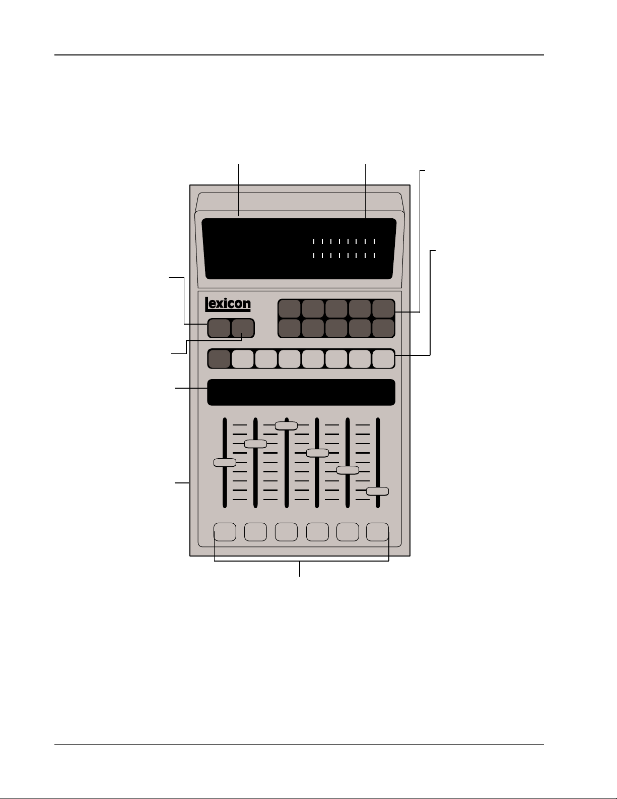
About the LARC
Program Select
Press to enter Program
mode. Press repeatedly to
scroll through presets in a
bank.
Register Select
Press to enter Register
mode. Press repeatedly to
scroll through registers in a
bank.
Slider Display Line
Shows abbreviated names
of the parameters currently
under the control of the sliders. Full name appears in the
Main Display.
Main Display
Shows names and values for
all selections.
PROG REG
VAR
Headroom Indicator
+12 dBm indicates analog or
digital clipping. Proper input
level is with +12 dB and ovld
LEDs
unlit
.
-24 18 12 6 0 6 +12 ovld dB
162738495
MUTE ENTER PAGECTRL MACHSTOBANK SETUP
Lexicon
Numeric Keypad
Press one of these keys to
load a program selected with
PROG or REG. Also used to
select pages.
L
Function Keys
R
0
Bank scrolls through
groups of programs or registers.
SETUP brings you to the
top level of the user interface.
STO stores edited setups
and program registers.
CTRL toggles in and out of
the control mode.
MACH toggles between
machines when Split or
Cascade setups are selected.
Control Sliders
Adjust parameter values.
1-6
MUTE toggles the removal
and restoration of processed audio from the outputs.
ENTER loads selected setups.
PAGE steps through pages
of setup and program parameters.
Slider Display Keys
Show parameter name and
value in main display. Press
twice to engage vernier (fine)
adjustment mode when
available.
Page 12

300L Service Manual
The 300L rear panel COMM PORT connector interfaces to the Lexicon
Alphanumeric Remote Control (LARC) via a flexible 50-ft cable (supplied). The
pin assignments for the connector are shown to the right.
Controls and
Connectors
How to Interface
the LARC
PUSH
COMM PORT
DOTIME CODE IN
AES/EBU
OUT
EIAJ CP340
DO DI
MIDI
THRU IN
DI
DO
R OUT R IN
L OUT L IN
PUSH
PUSH
INPUT
GAIN
DI
PUSH
Wiring diagram for the 300L
COMM PORTconnector.
1-7
Page 13

Controls and
-24 18 12 6 0 6 +12 ovld dB
L
R
Connectors
Lexicon
Setting Analog
Audio Levels
When shipped from the factory, the 300L is set for Analog I/O configuration.
Once you have connected the analog inputs and outputs, you should set up the
analog input (pre A/D converter) and analog output (post D/A converter) levels.
First, you will need to select a Setup which represents a digital “straight wire”
through the box. To do this, press the SETUP key, then use the PRE slider to
select Setup Preset 81.
The upper display should read:
STEREOADJUST
SG: SET P 81
Press ENTER to load the setup. Press CTRL, then press PAGE, followed by the
number 9. This will display Control Mode Page 9. The lower display will show:
IN: LFT RT OUT: LFT RT
The I/O structure of the box is specified such that if a +11dBu signal is input into
the box, full scale conversion will occur. This is indeed true if the LFT (left) input
and RT (right) input sliders are set to 0dB. In fact, with the Output sliders set to
0dB, you should read exactly the same, +11dBu. In practice, analog I/O interface
levels vary widely with various console types. The Input and Output controls on
page 9 allow the 300L to be optimized for use throughout the analog world.
With the Left and Right sliders fully attenuated to -10dB, the 300L can look at
signals as high as +21dBu. For those of you who like to “blast” through an analog
console, this full attenuation may be a requirement.
If your console typically sends a +4dBu signal when the send meters read 0VU,
the 300L’s input will be left with only 7dB before converter saturation. This is not
good. A common rock and roll solution would be a quick trim of the send masters
by -7 or -10 dB to give the system a little more “breathing room”. Some analog
engineers often refer to this “breathing room” as headroom. Technically , there
is no such thing as headroom in a digital system. When the converter goes to full
scale, overload will occur. Although this solution will usually work, we suggest
you trim the inputs to the 300L.
To do this, move the LFT and RT input sliders to the required settings. You may
need to “null” these sliders at their mid-travel points in order to “grab” the default
value of +0dB. Attenuate them one at a time and make sure they are matched.
Pressing the buttons under each of the active sliders will interrogate the current
values.
1-8
Page 14

300L Service Manual
Input levels between -1.5dBu and -2.9dBu will reference to 0 on the LARC
meters. You will find your own region of optimization.
On the output side, if +11dBu isn’t quite enough oomph! for the return inputs
(which is rarely the case) you may need to crank up the outputs. If you have
attenuated the inputs, as in the above example, the output will not be at unity gain
so you will have to boost the output sliders by the same amount. Grab each slider
individually and match the outputs.
A note on metering reverberation programs
Most Setups have the meters set for EFX-OUT. What we have described above
is getting the input and outputs “environmentally” matched.
As you start running reverb programs, you will see a natural attenuation on the
meters. This is perfectly normal. If the LARC overload LEDs do light up, DSP
overload is occurring. This is usually linked to someone’s “aggressive analog
behavior”, but there may be other times when an effect running in a delay
program has too much feedback and cross-feedback. A common pre-mastering
mistake is to run close to the edge going into an EQ process before going digitally
into a DAT. Boosting high or low frequencies is likely to overload the DSP output.
Be aware!
Controls and
Connectors
1-9
Page 15

Controls and
Connectors
Lexicon
Periodic
Maintenance
Obtaining Factory
Parts and Service
Ordering Parts
Under normal conditions the 300L requires minimal maintenance. Use a soft,
lint-free cloth slightly dampened with warm water and a mild detergent to clean
the exterior surfaces of the unit.
Do not use alcohol, benzene or acetone-based cleaners or any strong
commercial cleaners.
Avoid using abrasive materials such as steel wool or metal polish. If the unit is
exposed to a dusty environment, a vacuum or
to remove dust from the 300L exterior.
When ordering parts, identify each part by type, value and Lexicon Part Number.
Replacement parts can be ordered from:
Lexicon Inc.
100 Beaver Street
Waltham MA 02154
Telephone: 617-736-0300
Fax: 617-788-0499
low-pressure
blower may be used
Returning units
for service
ATT: Customer Service
Before returning a unit for warranty or non-warranty service, consult with
Lexicon to determine the extent of a problem and to obtain Return
Authorization. No equipment will be accepted without Return Authorization from Lexicon.
If you choose to return a 300L to Lexicon for service, Lexicon assumes no
responsibility for the unit in shipment from customer to the factory, whether the
unit is in or out of warranty. All shipments must be well packed (using the original
packing materials if possible), properly insured, and consigned to a reliable
shipping agent. When returning a unit for service, please include the following
information:
• Name
• Company name
• Street address
• City, State, Zip Code, Country
• Telephone number (including Area Code)
• Serial number of unit
• Description of the problem
• Desired return date
• Preferred method of return shipment
Please include a brief note describing conversations with Lexicon personnel and
give the name and telephone number of the person directly responsible for
maintaining the unit.
1-10
Do not include accessories such as manuals, cables, etc. with the unit
unless specifically requested to do so by Lexicon Service personnel.
Page 16

2
Performance
Verification
Page 17

Performance Verification
Lexicon
Introduction
This section attempts to guide the troubleshooting technician through the
process of verifying the proper operation of all of the 300L systems and subsystems. It is assumed that the reader is a qualified technician that is familiar with
the operation of the 300L and the required test equipment. A good understanding of how the 300L
Before attempting to perform any of the detailed tests outlined in this document,
a list of symptoms should be generated based on user complaints and some
basic system tests (listening, etc...). In most cases the technician is not the
person who encountered the problem. As a starting point, try to recreate the
symptoms on the bench and add your own notes to the original user’s notes.
Check the following:
• odor (Do you smell burnt components?)
• mechanical damage (Was the unit dropped or something dropped on the
unit?)
• mechanical sounds on power up (You should hear relays click on power up.)
• loose components rattling around inside unit
Verify that all of the troubleshooting tips outlined in the Owner's Manual and at
the end of this section have been checked. This will help eliminate any
unnecessary service due to operator error. These troubleshooting tips should
be tried
before
should
attempting to perform the entire Proof of Performance.
behave is essential to debugging a defective system.
2-2
Page 18

300L Service Manual
Performance Verification
Initialization and
Inspection
Remove the top cover of the unit as follows: Remove the 3 screws that hold each
rack ear. Remove the 3 remaining screws on each side of the unit, screw(s) in
the front of the top cover, and 1 screw in the upper center of the rear panel.
Remove the cover by gently spreading the bottom of each of its sides and lifting.
Inspect the unit for any obvious signs of physical damage.
Verify that all screws and hardware are tight.
Verify that the fuses on the Power Supply board are not blown. If fuses are
replaced, use those indicated in the following table:
LINE F1 F2 F3 F5
100/120v .5A .5A 3.15A .500A
5x20 5x20 5x20 3AG
230v .5A .5A 3.15A .250A
5x20 5x20 5x20 5x20
Verify that the XLR connector are tight by plugging a connector into each jack.
If the XLR connectors feel loose, tighten them by turning the lock clockwise with
the “XLR Lock Screw Driver”.
Initial Inspection
Required Equipment
Clean, antistatic,
well-lighted work area.
Male XLR Connector
Female XLR Connector
(cable not required, but
can be used)
XLR Lock Screw Driver
(Neutrix Part #140)
Check all ribbon cables for proper seating.
Verify that both W4 and W5 on the Host board are in the righthand position (as
viewed from the front of the unit). Note: these jumper blocks are not available on
Rev. 1 Host boards.
Check all socketed components for proper seating and bent pins.
Verify that fiche paper (protective covering) has been installed on the bottom of
the power supply board.
Check the AC power cord for signs of physical damage.
DSP
Analog
Host
Power
Supply
2-3
Page 19

Performance Verification
Lexicon
Power Supply
Required Equipment
Clean, antistatic,
well-lighted work area
300L Power Cord (Lexicon
#680-00841)
Variac or comparable vari-
able AC line source
(1Amp)
Digital Multi-Meter (DMM)
Oscilloscope (min. 20mHz
with a X10 probe)
To check the 300L's power supplies, remove the top cover as described under
Initial Inspection and perform the following tests. (Refer to Power Supply
schematics at the end of this manual.)
System Current Draw
Slowly power up the 300L with the Variac to rated line voltage.
Observe the AC line current on the Variac and verify that it is <0.4amps for 100/
120v or <0.2amps for 220/240v line voltages.
+5V Digital Supply Check
Measure the voltage between pin 2 (+5V) & 6 (DGND) of the cable plugged into
J9 on the Host board.
Verify that the voltage is between +4.9VDC and +5.1VDC. If the voltage is
outside of this range, adjust R3 on power supply board for +5.00VDC +0.1V.
+12V Supply Test
Measure the voltage between the front of FB (ferrite bead) 4 and the front of R22
on the Host board. Verify that the voltage is between +11.40 and +12.60VDC.
-12V Supply Test
Measure the voltage between the front of FB3 and the front of R22 on the Host
board. Verify that the voltage is between -11.40 and -12.60VDC.
+15V Supply
Measure the voltage from the +15V pin of J2 on the Analog board to the left side
of C6 (analog ground). Verify that the voltage is +14.25 to +15.75VDC.
-15V Supply
Measure the voltage from the -15V pin of J2 on the Analog board to the left side
of C6. Verify that the voltage is -14.25 to -15.75VDC.
+5VA Supply
Measure the voltage from the +5VA pin of J2 on the Analog board to the left side
of C6. Verify that the voltage is +4.75 to +5.25VDC.
-5VA Supply
Measure the voltage from the -5VA pin of J2 on the Analog board to the left side
of C6. Verify that the voltage is -4.75 to -5.25VDC.
Battery
Power down the unit. Measure the voltage across BAT 1 on the Host board.
Verify that the voltage is >2.5VDC.
2-4
Page 20

300L Service Manual
Performance Verification
Set the DMM for 750VAC and attach the probes to the blue and brown wires at
the AC receptacle on the 300L.
Reduce the AC line voltage. Verify that the AC line voltage is above the -25%
voltage, and below the -15% voltage for the appropriate nominal line voltage as
shown in the following table.
Nominal -25% -15%
100VAC - 75VAC 85VAC
120VAC - 90VAC 102VAC
220VAC - 165VAC 187VAC
230VAC - 100VAC 216VAC
Return the AC line voltage to the nominal level.
Verify that W4 and W5 on the Host board are in the righthand position (as viewed
from the front of the unit).
Connect the XLR cable from the Time Code output of the timecode generator to
the Time Code input on the 300L.
Power Fail
Timecode Tests
On the LARC, press CTRL, Page, then 7. The upper display should read:
TIMECODE
DISABLED
Move the slider labeled OFF until the upper display reads:
SNAP =
00: 00: 00: 00
Set the timecode generator for “SMPTE DROP-FRAME.
Verify that the unit displays “SD—V” to indicate that it has identified the incoming
time code as SMPTE Drop and the timecode continues to increment on the lower
display of the LARC.
Set the timecode generator for “EBU”.
Verify that the unit displays “—E-V” to indicate that it has identified the incoming
time code as EBU and the timecode continues to increment.
Set the timecode generator for “FILM”.
Verify that the unit displays “—FV” to indicate that it has identified the incoming
time code as FILM and the timecode continues to increment.
2-5
Page 21

Performance Verification
Lexicon
Listening
Required Equipment
Clean, antistatic,
well-lighted work area
Low Distortion sine wave
oscillator
Headphone Amplifier
Bong/click generator
2 Audio cables w/ female
XLR connectors on one
end and connectors to
fit the bong/click gen-
erator and the oscillator
on the other end.
2 Audio cables w/ male
XLR connectors on one
end and connectors to
fit the headphone amp
at the other end.
Stereo Headphones
Setup
1. Connect the left and right outputs of the oscillator to the left and right inputs
of the 300L.
2. Connect the left and right audio outputs of the 300L to the left and right inputs
of the headphone amp.
Note: When performing the Listening tests with unbalanced equipment,
short pin 3 to pin 1 of cables connected to the analog input and output
connectors.
3. Set the oscillator to 200Hz @ about -20dBV.
4. Turn volume control on amplifier all the way to minimum.
5. Attach headphones to amplifier’s headphone jack.
6. Set the input gain switch on the rear panel of the 300L to the OUT position.
7. Turn on the amplifier.
8. Turn on the 300L. The LARC should go through its power up display
sequence and then display:
LARGE HALL
If LARGE HALL is not displayed at the end of this sequence, press BANK,
1, PROG, 1 on the LARC to load the Large Hall program.
9. Press CTRL to display:
CONTROL MODE
PAGE 1
If Page 1 is not displayed, press PAGE, then press 1.
10.Adjust slider 2 (labeled CLK) until the display reads:
CONTROL MODE
ANALOG 44K
Listen
1. Put on the headphones and slowly increase the amplifier volume to a
comfortable listening level.
2. Verify that the output of the unit is free of converter artifacts (grit, buzz, static,
etc.).
3. Listen to the reverb decay time for any break up or pops.
4. Turn off the oscillator and connect a bong/click generator. Play a bong
through the 300L and check the reverb again.
5. Press CTRL to return to Control mode, set the CLK slider to select 48K and
repeat the listing test.
Storing Registers*
Modify one of the system presets and store it in a user register.
Load another preset.
Power cycle the system (OFF/ON).
Reload the modified effect from the user registers and verify that it sounds the
same as it did when it was stored.
* Refer to the 300L Owner's Manual for operational instructions.
2-6
Page 22

300L Service Manual
Connections
Connect the 600Ω resistor to the input of the distortion analyzer.
Connect the audio cable with the male XLR between the oscillator output and the
left input of the 300L.
Connect the audio cable with the female XLR between the distortion analyzer
input and the left output of the 300L.
The following sections attempt to describe analog performance verification in
generic terms which can be applied to most types of audio tests. These sections
can also be used as a reference when troubleshooting failure of an Audio
Precision ATE test.
Setup
Power on the 300L.
Performance Verification
Audio Proof of
Performance
Required Equipment
Clean, antistatic,
well-lighted work area
Low Distortion audio oscil-
lator <0.01% THD
Distortion Analyzer that
can measure <0.01%
THD and perform level
measurements in dB
*Balanced audio cable with
a male XLR on one end
and the appropriate
connector on the other
end for the oscillator
output. Pin 2 on XLR is
hot.
600Ω resistor
Load the Stereo Adjust program by pressing BANK, 9, PROG, 1 on the LARC.
Press CTRL, PAGE, 9.
*Balanced audio cable with
a female XLR connector
on one end and the appropriate connector on
the other end for the distortion analyzer input.
Pin 2 on XLR is hot.
*NOTE: If the audio oscillator and/or the distortion
analyzer do not have balanced audio connections,
configure the appropriate
XLR connectors so that
pins 1 and 3 are ground and
pin 2 is hot.
2-7
Page 23

Performance Verification
Lexicon
Level Test
Frequency
Response
If necessary, adjust the appropriate sliders on the LARC so that input and output
levels are set to 0.00dB.
Set the oscillator for 0dBu output @1kHz and the distortion analyzer to measure
level in dB.Verify the output level is between +1dB and –1dB.
Take a 0dBr reference. On the LARC, adjust the slider labeled Left Input until it
displays–10.00dB, and verify the output level is between –9.00 and –11.00dB.
Adjust the slider to display +10.00dB, and verify the output level is between
+9.00 and +11.00dB.
Adjust the slider until it displays 0.00dB, then repeat the above procedure for the
slider labeled Left Output.
On the distortion analyzer, disable all filters. Vary the oscillator frequency from
20Hz to 20kHz and verify that the output level remains between +0.20dB and
-.20dB at all frequencies.
Enable the lowpass filter (10Hz-20kHz) if available.
Noise
THD
Crosstalk
Turn the oscillator off, and set the level meter on the distortion analyzer to
measure <–80dB. Verify that the reading is <–78dB.
Turn the oscillator on and set the distortion analyzer to measure THD at the .01%
range and at a level range where it can measure 11dB. Set the oscillator for
11dBu output @ 1kHz and verify that the reading on the distortion analyzer is
<0.01%.
Transfer the 300L audio cable connection to the right input and set the distortion
analyzer to measure a level of –80dB. Verify that the reading is <–80dB.
Set the oscillator for frequencies of 10kHz, 20kHz and 1kHz and verify the
analyzer reading is <–80dB at each frequency.
Set the oscillator for a frequency of 1kHz and the distortion analyzer to measure
a level of 0dB.
Transfer the 300L audio cable connections to the other side and repeat the
frequency response, noise, THD and crosstalk tests.
2-8
Page 24

300L Service Manual
Performance Verification
Power the 300L off, then on and verify that the following display sequence
appears on the LARC:
LEXICON
MAINFRAME
RESET
LEXICON
300L VX.XX
LARGE HALL
SG:SET P 1
If the program LARGE HALL is not displayed at the end of the power up
sequence, press BANK, 1, PROG, 1, to load the LARGE HALL program. Put on
the headphones and slowly increase the amplifier volume until it's at a comfortable listening level.
TO PREVENT DAMAGE TO THE UNIT, KEEP ONE CORNER
TOUCHING THE WORK SURFACE AT ALL TIMES.
Lift each corner of the 300L four (4) inches off of the worksurface and drop it.
Verify that no audio intermittence occurs during this action.
Power Up
Shock
On the LARC, press CTRL, then 1 to display:
CONTROL MODE
PAGE 1
Press the button below the slider labeled CLK and verify that the LARC upper
display reads:
SAMPLE RATE
ANALOG 48K
Move the CLK slider to its topmost position, then to the bottom of its range until
the display reads:
SAMPLE RATE
ANALOG 44K
Lift each corner of the 300L four (4) inches off of the worksurface and drop it.
Verify that no audio intermittence occurs during this action.
Inspect all visible components to make sure nothing has loosened, then press
PAGE, 3 to display:
CONTROL MODE
PAGE 3
Adjust the slider labeled COPY until the upper display reads:
COPY PROTECT
OFF
Press CTRL. The upper display should read:
LARGE HALL
300MA: B01 P1
2-9
Page 25

Performance Verification
Lexicon
DSP Board
Troubleshooting
Cable Connections
The DSP board in the 300L cannot be troubleshot in the field. Contact Lexicon
Customer Service if symptoms indicate DSP board failure.
The 300L contains a lot of cables and connectors, which naturally have a lower
overall reliability than raw PC boards or components. Vibration can eventually
break the strands of cables making them intermittent or even open. Connections
can become oxidized, corroded or contaminated with flux and become intermittent, open or resistive. In addition to these “natural” dangers of cables/connectors, poor seating at assembly can reduce the long term reliability of the
connection.
For all of these reasons, caution should be used when troubleshooting 300Ls.
Before any cables are removed, they should be carefully inspected for proper
seating and continuity between the following points.
for reference only
Host to DSP (J6/J9 pin Signal)
U18 pin 2 U46 pin 19 45 D0
31847D1
41749D2
5651D3
61553D4
71455D5
81357D6
91259D7
U33 pin 10 U52 pin 2 7 SLVST/
U32 pin 14 U45 pin 11 6/7 pin 15 SLVCSR
U25 pin 46 U52 pin 5 1 A0
U39 pin 3 U45 pin 1 J6/7 pin 7 RESET/
2-10
These are the minimum connections required to test the control lines from the
Host to the DSP. If these lines are showing continuity and you are still getting
errors on power up, there is probably a legitimate problem with the circuitry, but
you should still carefully inspect each cable before, during and after removal.
Page 26

300L Service Manual
Performance Verification
When troubleshooting any kind of equipment, intermittent problems are among
the most difficult to trace. The first step when troubleshooting any problem is to
collect as much information as possible. The following table outlines some basic
questions which should be answered before attempting to troubleshoot an audio
problem with the 300L:
Does the problem occur...
1. on one output only?
2. at certain signal frequencies only?
3. at certain signal level only?
4. in certain programs only?
5. at certain sample frequencies only?
6. with input only?
7. without input only?
8. temperature or shock sensitive?
all
In general, it is best to run
isolate the problem within the system. This can be vital when troubleshooting
subtle problems. While some system failures may cause a variety of tests to fail,
troubleshooting based on one type of symptom may be much easier than
another. For example, a bad capacitor may produce a high level of distortion and
a frequency response problem. The frequency response problem would be
easier to trace because the signal level can be monitored on an ordinary
oscilloscope.
of the audio proof-of-performance tests to further
Audio Problems
Probably the most useful piece of information is to determine whether the
problem is on both channels or on only one. If the problem is occurring on one
output only, the following assumptions can be made with some level of
confidence:
The power supplies are OK.
The system timing (clocks) is O.K.
The digital circuitry up to the oversampling filters is O.K.
These types of problems can be fairly easy to troubleshoot, as the working
channel can be used as a reference. With the same signal applied to both inputs,
compare the signal on both channels at various points along the analog signal
path. This may localize the problem fairly quickly.
The fact that the problem is occurring in both channels can be equally revealing.
The likelihood that the two separate components failed in the same way at the
same time is fairly remote. The problem can probably be traced either to a
component which is common to both channels, or to a system problem such as
a power supply or timing problem. If there is no output, refer to that section for
more troubleshooting information.
A unit with no output can be one of the easiest to troubleshoot. The reason for
this is very straightforward: the symptom is easy to see.—.no signal. Again,
determining whether one or both channels is bad can reduce the number of
suspected circuits dramatically. (See the previous sections.)
One Channel Bad
Both Channels Bad
No Output
When the system under test has no output from only one channel, the
problem can usually be easily traced by feeding a sine wave into both inputs and
comparing the left and right signals at various points in the circuit.
2-11
Page 27

Performance Verification
Lexicon
No Output, cont'd.
No output
with no relay click
on power up
Effects don’t sound
the same as when
they were stored
Note that from the A/D chip output to the oversampling chip on the DSP board
the left and right are combined into a single serial audio data stream. Any
problems related to one channel only will probably
not
occur in this circuitry.
When the system under test has no output from either channel, the first thing
to check is the
+15V power supplies on the Analog board. Verify that they are
within the specified voltage ratings. (See the proof-of-performance section.) If
they are OK, feed a sinewave into both inputs and check for signal at the output
of the A/D converter chip (U6 pin 16). If there
path indicated earlier in this section. If there
is
signal present, follow the signal
isn’t
signal present, check the +5VA,
-5VA and +5VD supplies at the A/D chip. If they are active check for the CHSEL
(sample clock), XCLK and BCLK clocks and follow the signal path back toward
the inputs.
If the +15V supplies on the Analog board are down with F1 and F2 on Power
Supply board blown, a problem on the Analog board is causing the fuses to blow.
Check the +15v supplies for shorts. Replace fuses (if blown), power up the
system and carefully check the MDACs for heat. A hot MDAC is usually bad and
will pull down the +15v supplies.
Effects that don’t sound the same as when they were stored can be caused by
a number things. To help localize the problem several preliminary tests should
be performed. Verification of the system’s ability to store and generate an effect
can usually be done by creating an effect, storing it, power cycling the unit
several times and checking the effect. If the effect has noticeably changed, the
problem is probably in the Host board’s static RAM (U21) or the battery circuitry.
If the effect seems unchanged, the fault may be in the DSP processors and the
audio signal path itself.
The LARC control
head will not light
Touching a LARC
slider resets unit
Because the analog circuitry and the DSP processors are both in the audio signal
chain, the two circuit groups must be divided using the BYPASS control. Load
the “Stereo Adjust” preset and listen for distortion or audible artifacts at the 300L
output . Put the unit into BYPASS and listen again. If the artifacts disappear, the
problem is probably on the DSP board. If the artifacts remain, the problem is
probably on the Analog board. In any case, you should check the sample clock
(CHSEL at pin 14 of U6 on the Analog board) for the correct sample frequency
(default in diagnostics is 48kHz). The sample clock (and all of the converter
clocks) are generated on the Host board.
Verify +20VDC at TP1 on motherboard and pin 5 of either LARC port on the 300L
rear panel. If +20 volts is getting to the LARC, proceed to troubleshoot the LARC.
(The LARC only needs power to operate.)
Check U11 on LARC (Signetics 4515s have proven to be unreliable. Replace
with RCA or other brand.
2-12
Page 28

300L Service Manual
Performance Verification
This section contains detailed descriptions of Audio Precision automated tests
for the 300L (version 3.50 or higher software). Although these tests will be most
useful for repair facilities with Audio Precision test equipment, it should be noted
for facilities without this equipment, that these descriptions cover the basic
information necessary to create similar tests with alternate audio test equipment. Note: The procedures and utilities used by Lexicon are not included. Users
may develop their own procedures, or contact Lexicon Customer Service.
Lexicon may elect to share these tools with authorized service centers, but will
not provide support to their use.
Most of the audio tests for the system are part analog and part digital. In general
input circuitry up to the A/D converter use the analog GENERATOR portion of
the Audio Precision to provide stimulus for testing and perform the actual
evaluation on the digital audio output (AES). Output circuitry from the D/A
converter onward uses the digital audio input (AES) for stimulus and performs
the actual evaluation on the analog outputs from the 300L using the Audio
Precision’s ANALYZER.
All of the A/D and D/A tests use the Audio Precision DSP program
GENANLR.DSP to perform digital audio tests. At the beginning of the procedure,
the GENANLR.DSP program is copied onto the PC RAM to improve the speed
performance of the procedure. All of the tests in the procedure call the DSP
program from the d:\ drive.
In order to automate the system test procedure a special mode was added to the
system software to allow the 300L to be controlled via MIDI (see APPENDIX A
for a list of commands). Two basic operating modes can be called which allow
the system components to be tested:
Analog I/O: Data from the AD chip is routed to both the D/A chips and the digital
audio output (A/D testing).
Digital I/O: Data from the digital audio input is routed to boththe D/A chips and
the digital audio output (D/A testing).
In Digital I/O mode, the 300L must derive its system word clock from the
incoming digital audio for proper synchronization.
Audio Precision ATE
Test Descriptions
Required Equipment
Audio Precision System 1
(with PCI card)
SYS-22 “A” for Analog
Only Testing
SYS-322 “A” for Full Digi-
tal I/O Testing
IBM PC (or compatible) with
a hard disk (see S1
manual for details)
Audio Input and Output
cables (see the appropriate section)
The 300L ATE Tests consist of a series of Audio Precision “TESTS” which are
sequentially executed by an Audio Precision “PROCEDURE”. The tests attempt
to qualify the 300L as thoroughly as possible in as little time as possible.
These procedures make use of a MIDI (Musical Instrument Digital Interface)
interface card (MPU 401 compatible) installed in the Audio Precision PC. The
MIDI interface is used in the 300L Automated System Test procedure to send
control changes into the 300L under test. The control changes messages set the
300L to the proper operating mode for the given test. In order to transmit these
commands from an Audio Precision procedure, a DOS command: APUTIL M,
was developed by Lexicon to capture any hex data entered on the command line
after the command and transmit it as MIDI data (i.e. APUTIL M f0 06 <Enter>).
In the 300L procedure, MIDI commands are used extensively to set up the unit
under test. APPENDIX A outlines the MIDI commands used in the procedure
and their applications. These commands are entered in the procedure in the
form: DOS APUTIL M f0 06 07 00 00 03 00 00 00 f7.
ATE Tests
MIDI Automation
2-13
Page 29

Performance Verification
Lexicon
Error Handling/
Data Collection
(Lexicon procedure)
If a test fails, the procedure will display a failure message and present the
following options:
View the failure
Quit to Audio Precision menu
Quit to DOS
Continue
If you choose to view the failure, the data will be printed after viewing the failure
and give you another chance to quit to the Audio Precision command menu by
typing <F1> or to quit to DOS by typing <ESC>. If you choose to continue, the
data will be printed immediately. In these cases, any subsequent tests will also
fail depending on the extent of the problem. Generally, if 2 or 3 tests fail, the test
should be halted and the unit debugged.
If the unit passes a given test, the procedure will continue on to the next test. All
test data can be saved and copied into the PASS directory on the data disk (A:\).
When the test procedure is completed, you will be prompted to select the data
handling option. Press <SPACEBAR> to test another unit, <F1> to return to
Audio Precision Menu or <ESC> to quit all testing. The data handling options
available depend on whether the unit passed or failed. When a unit fails one or
more tests, the following options are available:
1. Print all FAILED DATA to the printer only.
2. Save FAILED DATA as a file (serial #).PRN to “ERROR PATH”.
3. Print all tests, pass and fail.
4. Save all tests good or bad as file (serial #).PRN to error path
5. View ERROR file D:\ERROR.PRN
6. View PASS file D:\OKDATA.PRN
Make selection or press <SPACEBAR> for none. (Because the procedure
automatically prints out the ERROR data for any tests that fail, the most common
option taken is <SPACEBAR>. )
When a unit passes all tests, the following options are available:
1. Print all PASSED data to printer only.
2. Save data as file test (Serial #).PRN to A:\PASS\
3. Print custom report and save data as file (Serial #).PRN to
A:\PASS\.
4. View PASS FILE D:\OKDATA.PRN
Make selection or press <SPACEBAR> for none.
Tests which use a STEREO SWEEP will produce a printout with test results from
the left channel on the left and test results from the right channel on the right as
indicated in the following example:
dBu %THD %THD
-20 0.006 0.233
/\ /\ /\
GEN (oscillator) Left Channel Right Channel
The following sections outline each of the Audio Precision “TESTS”, list the pass
fail limits and indicate the associated file names.
2-14
Page 30

300L Service Manual
Performance Verification
Unless otherwise stated, the following settings will be used on all of the Audio
Precision tests:
Generator Analyzer
WAVEFORM SINE BP/BR FREQ AUTO
OUTPUT BAL DETECTOR AUTO RMS
50Ω FILTER OFF
FLOAT BANDWIDTH 0Hz 22kHZ
INPUTS 100kΩ
RANGE AUTO
DSP:
FILTER OFF
TUNING GEN
DETECTOR AUTO
RATE 48kHz
NPUT SERIAL
CH-1 A
CH-2 B
OUTPUT D/A OFF (for A/D tests)
SERIAL A&B (for D/A tests)
When the procedure is first loaded via a batch file, it prompts the operator to
setup the system as shown (see fig.1).
LEXICON M300L ATE TEST PROGRAM
Default Settings
Setup
Power up the 300Land connect it to be tested as follows:
Analog Outputs A —> A Analog Inputs
B —> B 300L
AES Out –> A Out 1 -> AES In (AP)
S/PDIF Out —>SWR122F 2
AES OUT —> AES IN
SPDIF Out —> SPDIF In
AES Out —> AES In
Optical Out A —> A Optical In
Optical Out B —> B Optical In
AP MIDI OUT —> 300L MIDI IN
300L MIDI THRU —> APMIDI IN
Press <Enter> on the A.P. keyboard when ready to continue
The APUTIL M T command is a self contained test for MIDI THRU and wrap
around. The MIDI OUT cable is connected to the MIDI IN connector on the 300L,
which reproduces the message at its MIDI THRU jack. The PC reads and verifies
the message back through it’s MIDI IN cable which is connected to the 300L MIDI
THRU jack. With the cables from the PC properly connected to the 300L, the test
is easily run by entering the command APUTIL M T F8 (or any other byte except
FF) in the Audio Precision’s DOS mode or from the PC’s command line.
MIDI THRU Test
2-15
Page 31

Performance Verification
Lexicon
Test Options
THD Calibration
After the procedure runs the MIDI THRU Test, the MIDI message: APUTIL M
MAP is sent to turn the MIDI Map on and select the 300L Stereo Adjust program.
Following the MIDI message the following setup prompt/menu appears on the
PC CRT:
Set the 300L as follows:
Set the rear panel INPUT GAIN switch OUT (0dB).
Press <Enter> to run the FULL system test (including MDAC)
or 1 to run a QUICK system test (WITH cal)
2 to run a QUICK system test (WITHOUT cal)
3 to run D/A tests only
4 to TROUBLESHOOT A/D problems
5 to TROUBLESHOOT D/A problems
6 for Test Notes and general information
7 for A/D Problem Log
8 for D/A Problem Log
For complete system qualification, the first option must be exercised. The other
options are available primarily for troubleshooting (as the MDAC portion of the
procedure alone takes almost 10 minutes)
The GEN is set for 997Hz at -49dBu and the analog outputs of the 300L are
checked for THD using an <F2> bargraph. The left channel is connected to
channel A of the analyzer and the right is connected channel B. The test comes
up with channel A as the default with the procedure changing the analyzer input
to B after A has been calibrated. No limits are attached to this test so the results
of the calibration will only show up at the D/A THD tests.
DAC Offset Calibration
The calibration is done at low levels where the distortion is much higher and
where it is desirable to improve performance as much as possible. Typical
distortion levels at this signal level are 2.3% THD+N.
Files: THD_TRIM.TST
Prior to running the DAC Offset Calibration test the MIDI message: DOS APUTIL
M EXT is sent to the 300L to set the unit to receive digital audio.
The purpose of the DAC test is to optimize the performance of the DACs by
calibrating the DC offset out of the devices to as close to 0VDC as possible with
all 0s as a source. As with all tests that require the 300L to receive digital audio,
the system sample clock must be put into the External Mode. (See User Guide.)
The DSP panel of the Audio Precision is set for a -997dB output level which
produces an output of all 0s. The actual offset is measured downstream from the
DACs at the op amps associated with the MDACs which control the output level
of the system. No limits files are associated with the test, but the operator is
requested to calibrate for an offset of <1mVDC.
Upon completion of the calibration, the 300L is returned to its crystal-based
48kHz sample clock via the MIDI message: APUTIL M 48 which sets the 300L
to 48kHz internal
2-16
Files: OFFSET.TST
Page 32

300L Service Manual
Performance Verification
Optical Digital I/O Test
Prior to running this test, the MIDI message: APUTIL M OPT <ENTER> is sent
to the 300L to select the Optical Digital Input.
This test verifies that the Optical Digital I/O is working by performing a Digital
Input to Digital Output distortion test. The DSP generator is set for an output level
of 0.00dBFS at a frequency of 1kHz. The test uses the BANDREJECT Filter.
Files: OPT_OUT.TST
DIGIOTHD.LIM
DIGTHDL.LIM
RCA Digital I/O Test
Prior to running this test, the MIDI message: APUTIL M RCA <ENTER> is sent
to the M300L to select the RCA Digital Input.
This test verifies that the S/PDIF (RCA) Digital I/O is working by performing a
Digital Input to Digital Output distortion test. The DSP generator is set for an
output level of 0.00dBFS at a frequency of 1kHz. The test uses the
BANDREJECT Filter.
Files: SDIF_OUT.TST
DIGIOTHD.LIM
DIGTHDL.LIM
D/D Tests
XLR Digital I/O Test
Prior to running this test, the MIDI message: APUTIL M XLR <ENTER> is sent
to the M300L to selects the XLR Digital Input.
This test verifies that the AES (XLR) Digital I/O is working by performing a Digital
Input to Digital Output distortion test. The DSP generator is set for an output level
of 0.00dBFS at a frequency of 1kHz. The test uses the BANDREJECT Filter.
Files: AES_OUT.TST
DIGIOTHD.LIM
DIGTHDL.LIM
A/A Gain Test
The A/A Gain Test checks the analog input to analog output gain characteristics
of the 300L through its signal path. The test sets the Audio Precision oscillator
(GEN1) at 0dBu, driving both Left and Right outputs at the same time INTO
600Ω. The test uses a STEREO AMPLITUDE SWEEP test. Note that the 300L
is set for unity gain (all 4 MDACs set for 0dB).
Files: A-AGAIN.TST
A-AGAINH.LIM
A-AGAINL.LIM
A/A TESTS
2-17
Page 33

Performance Verification
Lexicon
A/A Frequency Response Tests
FREQ RESP RIGHT (+) Test
FREQ RESP LEFT (+) Test
FREQ RESP RIGHT (-) Test
FREQ RESP LEFT (-) Test
Prior to running the following tests, the MIDI Sysex messages: APUTIL P 1
UNBAL+ <ENTER> and APUTIL P 1 UNBAL- <ENTER> are sent to the 300L
to select Unbalanced + Outputs, and Unbalanced - Outputs, respectively.
These tests check the frequency response through the analog signal path. The
outputs are tested for unbalanced + and then for unbalanced -. The analyzer
takes a signal level reference (F4) of the channel’s output at 1kHz then sweeps
the frequency of the oscillator, testing the output level at each frequency relative
to the reference. The test performs a table based sweep at the following
frequencies:
19,997Hz 0,007Hz 251Hz
16,001Hz 4,001Hz 61Hz
12,503Hz 1,999Hz 10Hz
The oscillator (GEN1) is set for 11dB below the A/D Converter limit. The left and
right channels are checked with separate tests to simplify setup and troubleshooting. The test performs an AMPLITUDE test of the 0dB reference level. Note
that the 300L is set for unity gain.
Files: FREQL.TST
FREQR.TST
A-AFREQ.LIM
A-AFREQL.LIM
FREQ.SWP
MDAC Tests
Prior to running the following tests, the MIDI Sysex message: APUTIL P 1 BAL
<ENTER> is sent to the 300L to sets the analog outputs for balanced mode.
The MDAC tests verify that all the MDACs (4) are working. It does this by first
setting the MDAC under test for unity gain 0dB. The test takes a 0dBr reference
(F4), changes the gain of the MDAC, takes a measurement against the 0dBr
reference and verifies the reading is within the limits. Certain gain levels for the
MDACs have been selected to verify the data bits (D0-D7) are working.
The MDACs are labeled :
Left Input (U2)
Left Out (U11)
Right In (U8)
Right Out (U15)
When the MDAC under test is set for + or -3.5dB, the hex value AA is written to
the MDAC. The binary value is 1010 1010.
2-18
When the MDAC under test is set for + or -9.5dB, the hex value 55 is written to
the MDAC. The binary value is 0101 0101. Selecting these values (55 & AA)
verifies that all the data bits are working.
Page 34

300L Service Manual
Due to the tolerance of the Audio Precision and the MDACs, a ±0.10dB limit has
been added to each measurement. So if the LSB (D0) was bad on an MDAC, the
test may not detect it. To eliminate this possibility, a procedure called BIT0 TEST
was written for each MDAC. This will verify if D0 (bit 0) is working by taking a 0dBr
reference when the MDAC is set for -9.5dB, lowering the MDAC level to -9.6dB
and then taking a measurement to verify the level is between -0.044dBr & -
0.12dBr. When the MDAC gets set to -9.6dBr, the hex value 54 is written to the
MDAC. The binary value is 0101 0100. Only bit 0 is different between the hex
value 55 and 54.
Each MDAC is tested as described below.
Negative MDAC Tests
LIN NEG MDAC -3.5dB LOUT NEG MDAC -3.5dB
LIN NEG MDAC -9.5dB LOUT NEG MDAC -9.5dB
LIN MDAC BIT0 TEST LOUT MDAC BIT0 TEST
RIN NEG MDAC -3.5dB ROUT NEG MDAC -3.5dB
RIN NEG MDAC -9.5dB ROUT NEG MDAC -9.5dB
RIN MDAC BIT0 TEST ROUT MDAC BIT0 TEST
1. The MDAC under test is set for unity gain 0dB via the following MIDI
messages:
APUTIL M LI0DB for left input
APUTIL M RI0DB for right input
APUTIL M LO0DB for left output
APUTIL M RO0DB for right output
2. The test takes a 0dBr reference.
3. The MDAC under test is set for -3.5dB via the following MIDI messages:
APUTIL M LINEG35 for left input
APUTIL M RINEG35 for right input
APUTIL M LONEG35 for left output
APUTIL M RONEG35 for right output
4. The test takes a measurement and verifies the reading is between -3.32 and
-3.68dB.
5. The next test sets the MDAC under test for -9.5dB via the following MIDI
messages:
APUTIL M LINEG95 for left input
APUTIL M RINEG95 for right input
APUTIL M LONEG95 for left output
APUTIL M RONEG95 for right output
6. The test takes a measurement and verifies the reading is between -8.99 and
-10.01dB.
7. The test takes a 0dBr reference.
8. The next test sets the MDAC under test for -9.6dB via the following MIDI
messages:
APUTIL M LINEG96 for left input
APUTIL M RINEG96 for right input
APUTIL M LONEG96 for left output
APUTIL M RONEG96 for right output
9. The test takes a measurement and verifies the reading is between -0.044
and -0.156dB.
Performance Verification
2-19
Page 35

Performance Verification
Lexicon
Positive MDAC Tests
LIN POS MDAC +3.5dB RIN POS MDAC+3.5dB
LIN POS MDAC +9.5dB RIN POS MDAC+9.5dB
LO POS MDAC +3.5dB R0 POS MDAC +3.5dB
LO POS MDAC +9.5dB RO POS MDAC +9.5dB
1. The MDAC under test is set for unity gain 0dB via the following MIDI
messages:
APUTIL M LI0DB for left input
APUTIL M RI0DB for right input
APUTIL M LO0DB for left output
APUTIL M RO0DB for right output
2. The test takes a 0dBr reference.
3. The MDAC under test is now set for +3.5dB via the following MIDI messages:
APUTIL M LIPOS35 for left input
APUTIL M RIPOS35 for right input
APUTIL M LOPOS35 for left output
APUTIL M ROPOS35 for right output
4. The test takes a measurement and verifies the reading is between +3.32 and
+3.68dB.
5. The next test sets the MDAC under test for +9.5dB via the following MIDI
messages:
APUTIL M LIPOS95 for left input
APUTIL M RIPOS95 for right input
APUTIL M LOPOS95 for left output
APUTIL M ROPOS95 for right output
6. The test takes a measurement and verifies the reading is between +8.99 and
+10.01dB.
7. The MDAC under test is set for unity gain 0dB via the following MIDI
messages:
APUTIL M LI0DB for left input
APUTIL M RI0DB for right input
APUTIL M LO0DB for left output
APUTIL M RO0DB for right output
2-20
The second test sets the MDAC for -9.5dB. At this setting the hex value 55 is
written to the MDAC. The binary value is 0101 0101.
The third test takes a 0dBr reference at the -9.5dB reading and then sets the
MDAC for -9.6dB. At this setting, the hex value 54 is written to the MDAC. The
binary value is 0101 0100.
All of the MDAC tests are performed with only 2 Audio Precision tests.
LMDAC.tst for the Left input and Left Output, RMDAC for the Right Input and
Right Output.
Files: LMDAC.TST 3_5H.LIM BIT0LO.LIM
RMDAC.TST 3_5.LIM -9_5.LIM
-3_5H.LIM 9_5H.LIM -9_5H.LIM
- 3_5.LIM 9_5.LIM BIT0HI.LIM
Page 36

300L Service Manual
Performance Verification
Prior to running the following tests, the MIDI Sysex messages: APUTIL M INT
<ENTER> and APUTIL M 48 <ENTER> are sent to the 300L to select the
Internal Word Clock and the Internal Word Clock For 48kHz, respectively.
A/D THD 48
The High Level Dist A/D 48 checks the THD+N of the analog circuitry from the
input jacks to the A/D converter. The serial audio data generated by the A/D
converter chip is routed through the bypass path of the DSP board to the ADI chip
on the Host board. The ADI chip converts the data to AES format and outputs
it to the Audio Precision via the AES (XLR) jack. The test is performed at an
oscillator level of 11dBu at the following frequencies:
9.2kHz 251Hz
10.007kHz 50Hz
997Hz
The total harmonic distortion + noise reading is acquired by passing the signal
under test through a band reject (BANDREJ) filter which removes the fundamental frequency (listed above) and measuring the resulting signal. Typically this
measurement is expressed as a percentage of the unfiltered test signal.
Files: A/DTHD.TST
THD-HIGH.SWP
THD-HI.LIM
A/D Tests
A/D THD 48 Low
The low level dist A/D 48 test is similar to the high level test except that the test
is performed at an oscillator level of -9dBu at the following frequencies:
19.2kHz
10.007kHz
997Hz
50Hz
The total harmonic distortion + noise reading is acquired by passing the signal
under test through a band reject (BANDREJ) filter which removes the fundamental frequency (listed above) and measuring the resulting signal. Typically this
measurement is expressed as a percentage of the unfiltered test signal.
Files: A/DTHDLO.TST
THD-LOW.SWP
THD-LOW.LIM
A/D Dynamic Range
The dynamic range test is actually a modified distortion test which is performed
at a signal level 60dB below the system limit. With the 300L set for unity gain,
the oscillator must be set for -49dBu to achieve this. The reading is measured
at 997Hz in dB and has 60dB subtracted from it to determine the dynamic range
of the system. The result must be below -84.94dB for the test to pass.
The Audio Precision executes this test using the COMPUTE DELTA function
which computes the delta (or difference) between the data from the most current
test (F9) and the data stored with a test on the disk. The test which gets used by
the COMPUTE DELTA function is specified under the NAMES DELTA (“Com-
2-21
Page 37

Performance Verification
Lexicon
pute Delta file”). For the dynamic range test, the test DYNR_REF.TST on the
hard disk which contains data values of 60dB for left and right channels, gets
used as the Compute Delta file.
In order to prevent false errors from being detected by the Audio Precision before
the COMPUTE DELTA has been performed, the dynamic range tests do not
have limit files attached to them when they are called. They are instead assigned
after the COMPUTE operation using the “NAMES UPPER dynr.lim <Enter>”
command. An F7 at this point checks the measurements against the limits.
Files: A/DDYNR.TST
DYNR_REF.TST (reference)
DYNR.LIM
A/D Signal to Noise
This test attempts to measure the residual noise generated by the A/D portion
of the 300L with no signal being fed to it. Because the A/D tests are performed
on the AES data out of the 300L, any measurement of level by the Audio
Precision DSP module will be an absolute measurement (no dBr). The test,
therefore, shuts off the oscillator and measures the signal level present at the
AES output. It should be noted that the signal is passed through a digitally
generated “A Weighted” filter in the Audio Precision DSP module to simulate the
effect of human hearing on the measured noise reading.
Files: A/DSN.TST
A/DSN.LIM
A-DSNL.LIM
CMR TestsLeft Channel CMR, Right Channel CMR
The common mode rejection tests check the ability of the balanced input circuitry
on the 300L to ignore extraneous signals which appear on both + and -signal
lines in the same phase. The Audio Precision is set to send the same signal
(same phase and level) to both + and - 300L analog inputs at the following
frequencies:
19.997kHz
0.007kHz
997Hz
61Hz
Any signal that shows up at the output of the 300L with this setup is either being
passed by the balanced inputs or being generated by the 300L (usually noise).
On the Audio Precision, the common mode output is selected in the GENERATOR panel “Output configuration” field as CMTST. The oscillator is set for 11dBu
with the measurement being made on the 300L AES output. For ease of testing,
a separate test exists for each channel. Note that no A Weighting filter is used
for this test.
2-22
Files: CMRL.TST
CMRR.TST
CMR.SWP
CMR.LIM
CMRL.LIM
Page 38

300L Service Manual
A/D Crosstalk
The cross talk test measures the amount of signal that bleeds through from one
channel to the next in the A/D section of the Analog board. The tests are
performed by sending a full scale signal (just below clipping) to one channel
while measuring the signal level present on the other channel with no input
applied. The test runs at an oscillator level of 11.66dBu at the following
frequencies:
19.997kHz
10.007kHz
997Hz
10Hz
Note that this test uses a special CROSSTALK mode of the Audio Precision
which automatically swaps GENERATOR and ANALYZER channels in a
STEREO sweep test to check both channels in one sweep.
Files: A-DXTALK.TST
XTALK.LIM
XTALKL.LIM
XTALK.SWP
Performance Verification
A/D Frequency Response
The A/D frequency response tests check the 300L’s ability to convert signal at
the balanced inputs to the AES output with a minimum of level shifting relative
to signal frequency.
Frequency response tests are usually performed by sending a 997Hz sinewave
to the unit under test, taking a reference measurement of the output signal
coming back, then measuring the output level of the unit at various other
frequencies relative to the reference level. This becomes a problem with the
Audio Precision because the DSP program which reads the incoming AES data
always measures the signal level of incoming serial audio as an absolute value.
The solution is to use the COMPUTE NORMALIZE function on the Audio
Precision to offset the DSP’s measurements relative to 997Hz. By entering the
command “COMPUTE NORMALIZE 1,997,0 <Enter>” on the Audio Precision
after a frequency response sweep (F9), all of the measured readings from the
DATA 1 field (left channel) are offset relative to measurement at 997Hz which
is set to 0dB. The command for the right channel is “COMPUTE NORMALIZE
2,997,0 <Enter>”. The net result of this is even better than the usual method
because the measurement at 997Hz is set to exactly 0db with no noise or drift.
The check against the limits is performed after the data has been altered using
the F7 function key.
In order to prevent false errors from being detected by the Audio Precision before
the COMPUTE NORMALIZE has been performed, the frequency response tests
do not have limit files attached to them when they are called. They are instead
assigned after the COMPUTE operation using the “NAMES UPPER a-dfreu.lim
<Enter>” and “NAMES LOWER a-dfrel.lim <Enter>” commands. An F7 at this
point checks the COMPUTEd measurements against the limits. Level measurements are made at the following frequencies:
2-23
Page 39

Performance Verification
Lexicon
21,500Hz 4,001Hz
17,989Hz 1,999Hz
16,001Hz 997Hz
12,503Hz 251Hz
10,007Hz 61Hz
10Hz
Files: A/DFREQ.TST
FREQ1U.LIM
FREQ1L.LIM
48_FR.SWP
A/D Frequency Response Emphasis
Prior to running the following test, the MIDI Sysex message: APUTIL M
EMP_ON <ENTER> is sent to the 300L to turn the Emphasis on.
Testing the frequency response with emphasis is the same as without, except
that another COMPUTE function is added to the test to compensate for the
emphasis. When the emphasis circuits are turned on in the 300L, the frequency
response of the system is altered to provide higher gain for higher frequencies.
The following table outlines the frequencies tested along with the associated
pre-emphasis gain in dB:
21,500Hz 9.69dB
17,989Hz 9.37dB
16,001Hz 9.12dB
12,503Hz 8.44dB
10,007Hz 7.66dB
4,001Hz 3.56dB
1,999Hz 1.30dB
997Hz 0.37dB
251Hz 0.03dB
61Hz 0.00dB
10Hz 0.00dB
The DSP module has no de-emphasis circuits, so it reads back the signal level
with the indicated gains. The problem is overcome with the Audio Precision
COMPUTE DELTA command which computes the difference between two
groups of data. The data in the table above is stored with the actual frequency
response test, a-dfreqe.tst. In the NAMES panel of that test, the test itself (adfreqe.tst) is identified as the Delta file which the COMPUTE DELTA command
uses for reference. After the test is loaded, a sweep is run (F9) to collect data from
the unit under test. The “COMPUTE DELTA 1 <Enter>” and “COMPUTE DELTA
2 <Enter>” commands are executed which subtract the gain value in the table
above from the data collected in the sweep for the left and right channels
respectively at the appropriate frequencies. From this point the test is performed
like the other frequency response tests.
2-24
Files : A/DFREQE.TST
48_FR.SWP
FREQ1U.LIM
FREQ1L.LIM
When the test is finished, the MIDI message: APUTIL M EMP_OFF <ENTER>
is sent to the 300L to turn the emphasis off.
Page 40

300L Service Manual
A/DTHD 44
Prior to running this test, the MIDI message: APUTIL M 44 <ENTER> is sent to
the 300L to select the internal 44.1kHz Word Clock.
This test checks the A/D section’s THD at a sample rate of 44.1kHz. The 300L
is put into the 44.1kHz xtal sample mode and Audio Precision checks the THD
at an oscillator level of 11dBu at 997Hz.
Files: A/DTHD1K.TST
THD-HIGH.LIM
When the test is finished, the MIDI message: APUTIL M 48 is sent to the 300L
to select the internal 48kHz Word Clock.
Performance Verification
General D/A Test Notes
All of the D/A tests are performed with the DSP module in the Audio Precision
generating the stimulus for the test (input to the 300L) and the ANALYZER
section performing the actual test. When troubleshooting ATE failures for the
300L it is vitally important to understand the role of digital audio in these tests.
First, the 300L must derive its sample clock from the incoming digital audio for
data to be properly received. (Refer to the drawing below .) The 300L is put into
the ext 48/48 sample mode which enables it to derive all of its audio-related
timing from the incoming digital audio. In this mode, digital audio enters the unit
through the AES jack (XLR) on the rear panel of the unit and is routed to the ADI
chip (U17). The ADI chip extracts a sample clock from the digital audio and
outputs it to the PLL circuitry. The PLL (phase locked loop) circuit compares the
current system sample clock with this external clock and adjusts the frequency
of the system clock to bring the phase of these two clocks as close as possible.
This locking of phase is extremely important for the system to read the incoming
digital audio properly. When troubleshooting D/A problems, you should always
be aware this chain of events. When troubleshooting failures in the first D/A test,
you should be particularly suspicious of digital audio problems.
AES Out
Audio Precision
Analog
Inputs
D/A Tests
AES
Input
Circuit
Compare
300L
Xtals
Xtals
ADI
Chip
WC Out
MC
Select
DDI
DSP
Board
Routing
Clock
Dividers
D/A
Circuit
Timing
Clocks
2-25
Page 41

Performance Verification
Lexicon
Prior to running the following tests, the MIDI SysEx messages: APUTIL M XLR
<ENTER> and APUTIL M EXT <ENTER> are sent to the 300L to selects Dig In
on the 300L for XLR and to select the External Word Clock.
D/A THD
This test checks the THD+N of the D/A section of the 300L analog board at a
sample frequency of 48kHz. This and all of the D/A tests are executed by feeding
digital audio (AES) to the 300L from the Audio Precision DSP module and
reading the analog output of the 300L on the Audio Precision’s analog ANALYZER section (see the previous section for more info). The test sends a digitally
generated sinewave at a level of 0.00dBFS to the 300L at the following
frequencies:
19.2kHz
10.007kHz
997Hz
251Hz
50Hz
The ANALYZER section of the Audio Precision which makes the actual distortion
measurements is set for a 22kHz bandwidth with an A weighted filter.
Files: D/ATHD.TST
THD-HIGH.LIM
D-ATHDL.LIM
THD-HIGH.SWP
D/A THD 44
This test checks the THD+N of the D/A section of the unit under test at a sample
frequency of 44.1kHz. The DSP generator is set for an output level of 0.00dBFS
at a frequency of 997Hz. The test uses a 22kHz BANDWIDTH and an A weighted
filter.
Files: D/ATHD1K.TST
THD-HIGH.LIM
D-ATHDL.LIM
D/A THD LOW
This test checks the THD+N of the D/A section of the Analog board at a sample
frequency of 48kHz and a digitally generated signal level of -20dBFS. As with the
other D/A distortion tests, a 22kHz BANDWIDTH and A Weighted filter are used.
Distortion measurements are made at the following frequencies:
19.2kHz 997Hz
10.007kHz 50Hz
2-26
Files: D/ATHDLO.TST
THD-LOW.LIM
D-ATHDL.LIM
THD-LOW.SWP
Page 42

300L Service Manual
D/A Dynamic Range
The dynamic range test is actually a modified distortion test which is performed
at a signal level 60dB below the system limit. With the 300L set for unity gain,
the digital signal generator must be set for -60dBFS to achieve this. The reading
is measured at 997Hz in dB and has 60dB subtracted from it to determine the
dynamic range of the system. An “A Weighted” filter is used.
The Audio Precision executes this test using the COMPUTE DELTA function
which computes the delta (or difference) between the data from the most current
test (F9) and the data stored with a test on the disk. The test which gets used by
the COMPUTE DELTA function is specified under the NAMES DELTA (“Com-
pute Delta file”). For the dynamic range test, the test DYNR_REF.TST on the
hard disk which contains data values of 60dB for left and right channels, gets
used as the Compute Delta file.
In order to prevent false errors from being detected by the Audio Precision before
the COMPUTE DELTA has been performed, the dynamic range tests do not
have limit files attached to them when they are called. They are instead assigned
after the COMPUTE operation using the “NAMES UPPER d-adynr.lim <Enter>”
command. An F7 at this point checks the measurements against the limits.
Files: D-ADYNR.TST
DYNR_REF.TST (reference)
D-ADYNR.LIM
DADYNRL.LIM
Performance Verification
D/A Signal to Noise(Left & Right)
This test checks the residual noise generated by the D/A section of the 300L. The
test begins with the digital signal generator sending a full scale signal to the
300L. The Audio Precision takes a reference of the output signal (F4) then shuts
off the generator (F1) to take the signal to noise measurement (F9). The
ANALYZER uses an “A weighted” filter. The test is run separately for the left and
right channels with the ANALYZER input channel being changed by the
procedure to B for the right channel.
Files: D-ASN.TST
D-ASN.LIM
D-ASNL.LIM
D/A Crosstalk
The crosstalk test measures the amount of signal that bleeds through from one
channel to the next in the D/A section of the Analog board. The tests are
performed by sending a full scale signal to one channel while measuring the
signal level present on the other channel with no input applied. The test runs at
an digital signal level of 0.00dBFS at the following frequencies:
19.997kHz 997Hz
10.007kHz 10Hz
2-27
Page 43

Performance Verification
Lexicon
Note that this test uses a special CROSSTALK mode of the Audio Precision
which automatically swaps serial audio output and ANALYZER channels in a
STEREO sweep test to check both channels in one sweep.
Files: D-AXTALK.TST
D-AXTALK.LIM
D-AXTLKL.LIM
XTALK.SWP
D/A Frequency Response EMPH
Prior to running the following test, the MIDI SysEx messages: APUTIL M
DEMP_ON <ENTER>, and APUTIL M EMP_ON <ENTER> are sent to the 300L
to turn Digital Emphasis on and to turn Emphasis on.
Testing the frequency response with emphasis is the same as without, except
that another COMPUTE function is added to the test to compensate for the deemphasis. When the de-emphasis circuits are turned on in the 300L, the
frequency response of the system is altered to provide lower gain for higher
frequencies. The following table outlines the frequencies tested along with the
associated de-emphasis gain in dB:
21,500Hz -9.69dB 1,999Hz -.30dB
17,989Hz -9.37dB 997Hz -0.37dB
16,001Hz -9.12dB 251Hz -0.03dB
12,503Hz -8.44dB 61Hz -0.00dB
10,007Hz -7.66dB 10Hz -0.00dB
4,001Hz -3.56dB
The DSP module has no pre-emphasis circuits, so it transmits the signal level
with at a uniform signal level. This problem is overcome using the Audio
Precision COMPUTE DELTA command which computes the difference between two groups of data. The data in the table above is stored with the actual
frequency response test, d-afreqe.tst. In the NAMES panel of that test, the test
itself (d-afreqe.tst) is identified as the Delta file which the COMPUTE DELTA
command uses for reference. After the test is loaded, a sweep is run (F9) to
collect data from the unit under test. The “COMPUTE DELTA 1 <Enter>” and
“COMPUTE DELTA 2 <Enter>” commands are executed which subtract the gain
value in the table above from the data collected in the sweep for the left and right
channels respectively at the appropriate frequencies. From this point the test is
performed like the other frequency response tests.
Note that the pre/de-emphasis circuits can be turned on or off using batch
commands. See Appendix B for additional information.
Files: D-AFREQE.TST
48_FR.SWP
FREQ3U.LIM
FREQ3L.LIM
When the test is finished, the MIDI messages: APUTIL M DEMP_OFF
<ENTER> and APUTIL M EMP_OFF <ENTER> are sent to the 300L to turn
Digital Emphasis and Emphasis off.
2-28
Page 44

300L Service Manual
D/A Frequency Response
Prior to running the following tests, the MIDI SysEx messages: APUTIL P 1
UNBAL+ <ENTER> and APUTIL P 1 UNBAL- <ENTER> are sent to the 300L
to select Unbalanced + Outputs and Unbalanced - Outputs, respectively.
The D/A frequency response tests check the 300L’s ability to convert the serial
audio signal at the AES inputs to unbalanced outputs with a minimum of level
shifting relative to signal frequency.
Frequency response tests are usually performed by sending a 997Hz sinewave
to the unit under test, taking a reference measurement of the output signal
coming back, then measuring the output level of the unit at various other
frequencies relative to the reference level. Because the Audio Precision can only
take a reference of one channel at a time, two separate tests are usually required
to check both channels. In order to avoid running two tests, the procedure uses
the COMPUTE NORMALIZE function on the Audio Precision to offset the right
channel measurements relative to 997Hz. By entering the command “COM-
PUTE NORMALIZE 2,997,0 <Enter>” on the Audio Precision after a frequency
response sweep (F9), all of the measured readings from the DATA 2 field (right
channel) are offset relative to the measurement at 997Hz which is set to 0dB.
The net result of this is even better than the usual method because the
measurement at 997Hz is set to exactly 0dB with no noise or drift. The check
against the limits is then performed after the data has been altered using the F7
function key.
Performance Verification
In order to prevent false errors from being detected by the Audio Precision before
the COMPUTE NORMALIZE has been performed, the frequency response tests
do not have limit files attached to them when they are called. They are instead
assigned after the COMPUTE operation using the “NAMES UPPER d-afreu.lim
<Enter>” and “NAMES LOWER d-afrel.lim <Enter>” commands. An F7 at this
point checks the COMPUTEd measurements against the limits of ±0.26dB.
Level measurements are made at the following frequencies:
21,500Hz 1,999Hz
17,989Hz 997Hz
16,001Hz 251Hz
12,503Hz 61Hz
10,007Hz 10Hz
4,001Hz
Files: D-AFREQ.TST
FREQ5U.LIM
FREQ5L.LIM
48_FR.SWP
The test is performed again with the outputs of the 300L set for unbalanced mode
so that the analog output circuit is completely tested.
2-29
Page 45

Performance Verification
Lexicon
MIDI Commands
MIDI Command Application
F0 06 03 20 10 27 01 00 F7 44.1kHz Sample Rate
F0 06 03 20 10 27 00 00 F7 48kHz Sample Rate
F0 06 03 20 10 29 00 00 F7 Turns the Digital Emphasis Off
F0 06 03 20 10 29 01 00 F7 Turns the Digital Emphasis On
F0 06 03 20 10 28 00 00 F7 Turns the Emphasis Off
F0 06 03 20 10 28 01 00 F7 Turns the Emphasis On
F0 06 03 20 10 23 01 00 F7 Sets the unit for Digital Input
F0 06 03 20 10 23 00 00 F7 Sets the unit for Analog Input
F0 06 03 20 10 2C 64 00 F7 Sets the Left Input MDAC for 0.0dB
F0 06 03 20 10 2C 41 00 F7 Sets the Left Input MDAC for -3.5dB
F0 06 03 20 10 2C 05 00 F7 Sets the Left Input MDAC for -9.5dB
F0 06 03 20 10 2C 04 00 F7 Sets the Left Input MDAC for -9.6dB
F0 06 03 20 10 2C 07 01 F7 Sets the Left Input MDAC for +3.5dB
F0 06 03 20 10 2C 43 01 F7 Sets the Left Input MDAC for +9.5dB
F0 06 03 20 10 2E 64 00 F7 Sets the Left Output MDAC for 0.0dB
F0 06 03 20 10 2E 41 00 F7 Sets the Left Output MDAC for -3.5dB
F0 06 03 20 10 2E 05 00 F7 Sets the Left Output MDAC for -9.5dB
F0 06 03 20 10 2E 04 00 F7 Sets the Left Output MDAC for -9.6dB
F0 06 03 20 10 2E 07 01 F7 Sets the Left Output MDAC for +3.5dB
F0 06 03 20 10 2E 43 01 F7 Sets the Left Output MDAC for +9.5dB
F0 06 03 20 10 2D 64 00 F7 Sets the Right Input MDAC for 0.0dB
F0 06 03 20 10 2D 41 00 F7 Sets the Right Input MDAC for -3.5dB
F0 06 03 20 10 2D 05 00 F7 Sets the Right Input MDAC for -9.5dB
F0 06 03 20 10 2D 04 00 F7 Sets the Right Input MDAC for -9.6dB
F0 06 03 20 10 2D 07 01 F7 Sets the Right Output MDAC for +3.5dB
F0 06 03 20 10 2D 43 01 F7 Sets the Right Output MDAC for +9.5dB
F0 06 03 20 10 2F 64 00 F7 Sets the Right Output MDAC for 0.0dB
F0 06 03 20 10 2F 41 00 F7 Sets the Right Output MDAC for -3.5dB
F0 06 03 20 10 2F 05 00 F7 Sets the Right Output MDAC for -9.5dB
F0 06 03 20 10 2F 04 00 F7 Sets the Right Output MDAC for -9.6dB
F0 06 03 20 10 2F 07 01 F7 Sets the Right Output MDAC for +3.5dB
F0 06 03 20 10 2F 43 01 F7 Sets the Right Output MDAC for +9.5dB
F0 06 03 20 10 25 02 00 F7 Selects the Optical Digital Input
F0 06 03 20 10 25 01 00 F7 Selects the RCA Digital Input
F0 06 03 20 10 25 00 00 F7 Selects the XLR Digital Input
F0 06 03 20 10 0B 01 00 F7 Turns the 300L MIDI Map on
F0 06 03 20 10 0B 00 00 F7 Turns the 300L MIDI Map off
c0 50 (MIDI Map must be on) Selects the 300L Stereo Adjust Program
c0 00 (MIDI Map must be on) Selects the 300L Large Hall Program
2-30
Batch Commands
The following commands were written for troubleshooting Audio Precision
failures. The commands can be executed from the DOS Command Line option
of the Audio Precision Menu. To select the command line option from the menu,
press D followed by the command you want executed.
Command Contents Description
44 APUTIL M F0 06 03 20 10 27 00 00 F7 Sets the 300L for 44.1kHz
48 APUTIL M F0 06 03 20 10 27 01 00 F7 Sets the 300L for 44.1kHz
DEOFF APUTIL M F0 06 03 20 10 29 00 00 F7 Turns the Digital Emphasis off
DEON APUTIL M F0 06 03 20 10 29 01 00 F7 Turns the Digital Emphasis on
EOFF APUTIL M F0 06 03 20 10 28 00 00 F7 Turns the Analog Emphasis off
EON APUTIL M F0 06 03 20 10 28 01 00 F7 Turns the Analog Emphasis on
EXT APUTIL M F0 06 03 20 10 23 01 00 F7 Sets the 300L for Dig In
INT APUTIL M F0 06 03 20 10 23 00 00 F7 Sets the 300L for Analog In
Page 46

3
Circuit
Description
Page 47

Circuit Description
Lexicon
Architectural
Overview
A fundamental feature of the 300L is its dual-HSP architecture. There are two
independent HSP (Lexichip)-Z80 processor groups operating under the control
of a single 68008 MPU. Each of the different processors resides on a separate
circuit board. The 68008 is located on the Host PCB. The two Lexichip-Z80 audio
processors reside on the DSP PCB. In addition to these circuit boards the M300
contains:
1 Analog Board containing the A/D and D/A circuitry
1 Power Supply Board
4 smaller boards (2 Audio RAM boards, 1 Digital I/O and 1 Analog
I/O board) each containing connectors for their respective circuits.
(See Figure 3-1, System Block Diagram.)
Functionally, the circuitry can be divided into Host-Digital I/O, DSP-Audio RAM,
Analog-analog I/O, and Power Supply sections. Each section’s circuitry is
fundamentally different and is, therefore, presented separately here.
LARC
HOST BOARD
ANALOG BOARD
ANALOG I/O BOARD DIGITAL I/O BOARD
POWER SUPPLY BOARD
DSP BOARD
DRAM
BOARD
DRAM
BOARD
3-2
System Block Diagram
Page 48

300L Service Manual
Circuit Description
Host Board
DUART
INTRPT GEN
TC
READ
AES
INTERFACE
LARC
MIDICOMM
MASTER
CONTROL
PROCESSOR
68008
DTACK
GEN
RESET
GEN
SYSTEM CLOCKS
PLL
16.934
MHZ
ADDR
DECODE
CTRL
&
STATUS
18.432
MHZ
128K
EPROM
32K
SRAM
Clock
8MHZ
MDAC
INTERFACE
DSP INTERFACE
The Host Board contains circuitry for the host processor, program storage,
system clock generation, an AES conformant digital audio interface and interfaces to the Analog and DSP boards, LARC, midi ports, time code input, and
serial port.
The Host Processor monitors and updates the various control ports (i.e. the
LARC, MIDI, timecode, and the serial port). It translates data received from those
ports into control actions for the audio processing circuitry. It directly controls
audio routing, system sample rate, and analog audio I/O levels. It loads audio
effects code into the DSP slaves and drives parameter changes within those
processes. For some audio effects (pitch change, for example) it participates in
the audio processing through its ability to read the Peak Detect chips, which are
on the DSP board.
This processing is performed by a 68008 CPU (U25). It runs from a clock (8MHz)
derived from a crystal clock (U50) and a counter (U38).
The initialization of processing, for both power-up and manual reset (SW1) is
controlled by the signals RESET/ and HALT/. On power-up the RC network of
R42 and C63 delays the rise of the input to the inverter U48, guaranteeing a high
output for at least 120 milliseconds. This drives one input of the OR gate (U37),
which in turn drives the open-collector (U39) RESET/ and HALT/. When RESET
(SW1) is pressed, the RS flip-flop created from U31 drives the other input of the
OR gate (U37) high, also generating RESET/ and HALT/.
Host Board Diagram
The Host Processor
3-3
Page 49

Circuit Description
k
k
Lexicon
When RESET/ and HALT/ are released, the 68008 will begin processing by
attempting to read instructions from address 0. The counter (U52) sends a
modifier to the address decode PAL (U24), forcing the first 8 memory accesses
(which will be at 0x000000 - 0x000007) to be from ROM0. All subsequent
accesses are decoded as indicated in the figure below. The large scale decoding
is done by U24 and the register level decoding of PERIPH/ devices by U32, U33,
and U19.
Function
RAM0
ROM0
ROM1
ZRAM1
ZRAM2
DUART
PERIPH
SLVCSR
INTSWR
AINCR
AESCS/
TCCS/
SEGSEL
LEVEL
in left
out left
in right
out right
SLVDR/
INTSRD/
Host Board Memory Map
PEAK1
PEAK2
SLVST/
HEX Address
00000 - 07fff
10000 - 1ffff
20000 - 3ffff
80000 - 81fff
90000 - 91fff
f0000 - f1fff
f2000 - f3fff
f2008
f2010
f2018
f2020 - f2027
f2028
f2030
f2038 - f203f
f2038 - f2039
f203a - f2-3b
f203c - f203d
f203e - f203f
f2048 - f2049
f2050
f2058
f2060
f2068 - f2069
Size (x8)
32
64
128k
8k
8k
8k
8k
1
1
1
8
2
1
2
2
2
2
2
1
1
1
2
Notes
Battery Backup U21
Socket U23
Socket U22
DSP 1 Z80 RAM
DSP 2 Z80 RAM
DUART Internal Registers
Peripheral Devices
DSP Bd Slave CSR
Misc. Control Register
DSP Bd Audio Routing Register
Digital Interface Control (U17 & U56)
Time Code USART Internal Registers
7-Segment Display Register
Analog Bd MDAC Control
DSP Slave Status Registers
Misc. Status Registers
DSP Bd Peak Detect 1
DSP Bd Peak Detect 2
DSP Bd Slave Status Registers
3-4
Page 50

300L Service Manual
/
/
W
Circuit Description
The 68008 has an asynchronous bus interface. This means that when the 68008
initiates a bus cycle, it will normally not finish the cycle until it has received
acknowledgment from the addressed device (DTACK/). The Host board contains circuitry to handle a number of device-dependent cases:
Most of the on-board devices are sufficiently fast to issue a DTACK/ on the first
8MHz cycle after data strobe. This creates a psuedo-synchronous cycle with 0
wait states for reads and 1 wait state for writes. See Figure below.
S0 S2S1
S3 S4
W
W
S5
8MHZ
AS
SYNCDT/
DTACK
R/
68008 Bus Interface
S6
S7
S0
DS/ (WR)
ZWR/
DATA (OUT)
8MHZ
DS/ (RD)
ROMø1
R/WINV/
DATA (IN)
S0 S2S1
S3 S4
W
4
W
2
S5
S6
5
S7
S0
6
Synchronous Bus Timing
3-5
Page 51

Circuit Description
Lexicon
Other devices, specifically the DUART (U20) and the DSP board Slave ZRAM,
will take a longer and indeterminate amount of time to respond. Either case
drives U35 pin 12 high and this in turn will drive U46 pin 12 low on the next edge
of 8MHz. This will hold off DTACK/ until either the DUART acknowledge
(DDTACK/) or the ZRAM acknowledge (DMAACK) is asserted.
As mentioned above, the 68008 suspends processing during a bus cycle until
DTACK/ is asserted. This means the system will hang if DTACK/ does not work
as expected. The 68008 can recover from an unterminated bus cycle (DTACK/
not asserted) if a circuit is provided that drives the BERR/ input low after some
time interval. The BERR/ generator is a 74HC393 (U36) wired as a divide-by-256
counter, and an inverter (U34). When AS/ is asserted at the beginning of a bus
cycle, the counter begins counting 4MHz cycles. If 128 cycles are counted (32
usec) and AS/ is still asserted, pin 6 of the 393 goes high. This is inverted to
generate the BERR/ signal. BERR/ causes the 68008 to begin exception
processing. AS/ is released, which resets U36, clearing the BERR/ signal. In a
normal cycle, AS/ is de-asserted in less than 32 usec and the counter is reset
before BERR/ is asserted.
Interrupts
Memory
There are only two sources of interrupts: PF/ (power fail, from the power supply)
and DINT/ (from the DUART). These are encoded by U51 so PF/ will generate
a level 7 interrupt (highest priority), and DINT/ will generate a level 5 interrupt.
During the interrupt acknowledge cycle, address lines (A3:A1) will output the
interrupt level and (FC2:FC0) will all be high, causing U35 to drive IACK/ low. At
this time, A2 distinguishes between level 5 (A2 low) and level 7 (A2 high). These
conditions are decoded by U37. A level 7 (PF/) interrupt will cause VPA/ to be
driven. VPA/ low will cause the 68008 to process a level 7 autovectored interrupt.
Exception processing will execute the code pointed to by interrupt vector 31. A
level 5 interrupt (DINT/) causes DIACK/ to be driven to the 68881 DUART. This
will cause the DUART to drive a software loaded interrupt vector to the data lines
and to assert DTACK/. Exception processing will execute the code pointed to by
that vector.
All program (Host and DSP) and preset data is stored in PROM at locationsU23
(low addresses) and U22. These sockets will accept either standard pinout 64K
by 8-bit parts (These must be installed in the sockets bottom justified, i.e. the
part’s pin 1 should be in the socket’s pin 3.) or 128K by 8-bit parts.
All Host RAM is contained in the device at U21. The location is configured for
standard-pinout 32k by 8 bit devices. U21 has a backup battery and circuit
intended to provide reliable parameter storage during periods without power.
When RESET/ is low (during power-up or manual reset) the chip enable to RAM0
(CE1/) is disabled to prevent spurious write strobes from altering the data. This
protection is also provided if the Vcc level falls below 3.9 volts (the base current
for Q4 is pinched out against the Zener CR6).
3-6
Page 52

300L Service Manual
Circuit Description
The 68681 Dual Universal Asynchronous Receiver/Transmitter, U20, is a
multifunction device that implements the following functions:
• MIDI serial port handling
• Communications port serial handling
• Time code clock generation
• Software system timer
• Interrupt handling for serial ports(MIDI, time code and communications port),
system timer, front panel communications, and digital interface events.
• An 8-bit parallel output port
There are many sources which may initiate a Duart interrupt. These sources
include the MIDI port , the Comm port, the Front panel interface , Time code and
finally the AES interface. Time code SYNC detect and data available interrupts
and the AES interface receive block interrupt, RBLKINT/ are detected and
controlled through OR gate U43, buffer U30 and latch U29. This structure
provides the ability to enable or mask the source of the interrupt. The signal INT
generates an active signal through U43 to DUART input port, IP2.
The DUART has six available input ports, IP0 - IP5, and eight output ports, OP0
- OP7, which can be configured in many different ways.
The DUART
DUART Interrupts
Input/Output Ports
Input Ports ADDR = F000Dh
Three input bits on the DUART are used to detect delta changes on the lines
driving them. These bits are IP0 - IP2. The function of the bits are:
IP0 - MDAV (Master Data Available)
Front panel interface — not used in the 300L.
IP1 - FPDAV (Front Panel Data Available)
Front panel interface — not used in the 300L.
IP2 - INT (Interrupt)
This bit is used to indicate that an interrupt has been generated by either the
Timecode USART or the AES interface. It is the logical OR of these two sources
and a high level indicates that the interrupt is active. To determine which source
is active the Host must read the MSRD register.
DUART Input Ports
3-7
Page 53

Circuit Description
Lexicon
DUART Output Ports
Output Ports Bit Set ADDR = F000Eh, Bit Reset ADDR = F000Fh_
OP0 - BYP (Hard Bypass)
BYP, when high, puts the Analog Board into bypass mode via relays. The signal
is supplied by bit 0 on the output port of the DUART. This output is then inverted
in order for it to be in the active state on power-up (output port pins on the DUART
power up in the high state). The signal is ORed with a power-on/off detection
circuit on the Analog Board itself. This circuit is presently configured to hold the
relays in bypass for approximately 1.5 seconds on power-up. Calibration of the
ADC (mentioned above ) should take place approximately one second after
power-up to allow as much time for the ADC to stabilize. Once the ADC has
completed its autocal routine and program is loaded into the DSP chip(s) the
BYP signal should be driven low thereby taking the unit out of the software
bypass mode. If the power-on/off detection circuit has completed its cycle by this
time audio will be passed from input to output. It should be noted that in bypass
mode, the analog input connectors are routed directly to the output connectors
and are disconnected from the unit's input circuitry. The bypass relays take
about 5mS to switch out of bypass and about 2ms to go into bypass.
OP1 - EMPH/ (Emphasis)
Both the pre and de-emphasis circuitry are controlled by output port bit 1 on the
DUART. On power-up the default condition leaves the emphasis circuitry out of
the audio paths. By setting the output port high the circuitry is switched into the
path. It should be remembered that for digital audio (AES data) emphasis in any
form has no effect.
OP2 - 31.25K (Timecode State Machine Clock)
This bit is controlled by setting up the OPCR, output control register, to provide
the MIDI transmit clock at this pin.
OP3, OP4 - CHAR1/, CHAR2/ (Diagnostic Display Characters 1, 2)
These two ports turn-on source current to the two seven segment displays on
the Host Board. When used in conjunction with SEGSEL displays are time
multiplexed for displaying diagnostic codes.
OP5, OP6 - DIFSEL0, DIFSEL1 (Digital Input Format Select Bits)
There are three electrical formats in which the 300 can receive digital audio.
These bits select the format. They are:
DIFSEL1 DIFSEL0 Format
0 0 AES/EBU
0 1 EIAJ CP 340 - RCA Phono
1 0 EIAJ CP 340 - Optical
1 1 not used
3-8
Page 54

300L Service Manual
Circuit Description
TCCS/ (Time Code Chip Select) ADDR = F2028h, Data ADDR = F2029h Control
This strobe is used for addressing the time code USART.
The front end of the circuitry for Time Code reading is PAL U41. This circuitry
detects the incoming differential signal, and converts to a bi-phase encoded bit
stream.
The time code PAL, U41, extracts serial data and clock from incoming bi-phase
encoded data using a state machine clocked at 31.25 Khz. The state machine
can be thought of as a counter that counts from 0 to 10 and “sticks” until a
transition in the data is detected. Transitions occurring before the counter has
reached 10 are latched by asserting the DATA output. When the counter reaches
10, it generates a positive data clock, RXC, edge. Transitions occurring while the
counter is held in state 10 cause the counter, RXC, and DATA outputs to be
reset. Data sent to the USART is in NRZ form. See Figure 5 for State Diagram.
Transitions are detected within the PAL by generating two outputs, TCRZ1 and
TCRZ2, which are simply latched versions of the input data, delayed by one and
two 31.25 Khz clock periods, respectively. A transition occurs when TCRZ1 is
not equal to TCRZ2.
Time Code Chip Select
Time Code Input
Time Code Extraction
The range of time code rates that can be decoded is approximately +15%
SMPTE (30 frames per second) and - 15% for Film (24 frames per second). The
critical parameters are the state machine clock frequency and the highest state
count (which is 10 here). The range can be determined by considering what the
DATA and RXC outputs generate when a square wave of variable frequencies
are applied to the input of the PAL. For example, a stream of “1s” at the nominal
SMPTE frame rate is a 2400 Hz square wave (10 bytes per frame = 80 data bits,
30 frames per second); a constant stream of zeros would be a 1200 Hz square
wave.
The critical factor determining the upper frequency limit of operation for 30 frame
per second time code is computed by determining the highest frequency square
wave that still generates clocked “zero” data as output. From the state diagram,
this is a square wave with a half-cycle period of 11/31250 ≅ 1420 Hz, which is
≅18% above the frequency for normal speed, 30 frames per second time code
(1200Hz)
Determining the lower frequency limit of operation for 24 frames per second time
code is computed by determining the lowest frequency square wave that still
generates clocked “one data as output. From the state diagram, this is for a
square wave with a half cycle period of 10/31250 ≅ 1563 Hz, which is ≅18% below
the frequency for normal speed, 24 frames-per-second time code (1920Hz).
SEGSEL/ (7 -Segment Display Select) ADDR = F2030h
Limits of Operation
3-9
Page 55

Circuit Description
Lexicon
RXC=0
Legend
S
D=?
STATE
0
D=0
TRANS
S=5[3..0]
STATE
of
1
D=0
D=1
DATA
1
TRANS
D=0
D=1
2
2
TRANS
3
D=0
3
D=1
TRANS
4
D=0
D=1
4
TRANS
TRANS
TRANS
5
D=0
5
D=1
TRANS
6
D=0
D=1
7
D=0
TRANS
6
7
D=1
TRANS
8
D=0
8
D=1
TRANS
10
RXC=1
D=0
ASSERT
RXC (4)
10
RXC=1
D=1
9
D=0
TRANS
9
D=1
Time Code State Diagram
7-Segment Display Select
AES Chip Select
This strobe is used to drive segments on the diagnostic displays mounted on the
Host board.
AESCS/ (AES Chip Select) ADDR = F2020h
This strobe is used to enable writing or reading of the AES interface chip.
Master Clock can be selected from any of three sources via multiplexer (MUX)
3-10
Page 56

300L Service Manual
Circuit Description
System Clock
Generation Circuits
IC, U10. These three sources are an 18.4320MHz (384 times a 48.000 kHz
sample rate) and a 16.9344MHz (384 times a 44.100kHz sample rate) CMOS
crystal oscillator modules, and the output of the phase-locked loop, PLLCLK, the
frequency of which (when selected and locked) would be 384 times the sample
rate of the incoming digital data.
Selection of the clock source is controlled by the signals MCSEL0 and MCSEL1.
On power-up, these signals are held low, which results in the 18.4320MHz clock
being selected. Due to the relatively large fanout of the master clock in this unit,
both halves of the MUX IC are utilized for selecting the clock. The signal MC1
is used to feed the dividers and latch IC described earlier, while the other output,
MC, goes to J1, which connects to the DSP Board. The signal MC is equipped
with a passive parallel termination on the DSP board, in order to optimize the
waveform of this high frequency signal.
The two crystal oscillator modules can be deactivated while the phase-locked
loop (PLL) is selected in order to minimize the pickup of spurious noise and beat
frequencies in the PLL. This is accomplished by removing the +5V power to
these modules via PNP transistor Q3 and signal XTALEN/. Like the MCSEL
lines, this signal powers-up in the low state, thereby enabling the oscillators.
When reverting to master mode (crystal) from the PLL, the XTALEN/ signal is
applied at least 20mS before the MCSEL signals are changed, in order for the
modules to properly power-up and their frequency stabilize.
Master Clock
Clock Source
All sample-synchronous clocks used in the 300L are generated by a series of
synchronous counters on the Host Board. These counters are arranged in three
groups, the first divides the master clock (MC1) by 384, the second divides MC1
by 16, and the third combines signals from both sections to generate a gating
signal.
The first section is composed of a counter, U6, configured as a divide-by-3 stage,
to generate 128Fs. This then feeds a divide-by-16 stage, U5, which, in turn,
feeds U4, configured as a divide-by-8. The RCO (ripple-carry output) of U4 is 1/
384th of the master clock frequency, which puts it at the sample rate, Fs. This
signal is NOR’d with the RCO of the first counter, so that on start-up, the 128Fs
generated by this first counter will become properly phase-aligned with the
clocks generated by the following two counters.
The second section is a single divide-by-16 counter, U3. It generates a 48Fs
clock and provides the count enable signal to the third section. This counter is
loaded at the sample rate.
The third section, U2, generates a gating signal which is used to gate the input
bit clock to the digital filter chip. This bit clock must have 32 cycles per sample
period (16 bits x 2 channels), while all the serial audio data in the unit is clocked
at 48Fs. The gating signal is low for the first 16 of the 24 bit cells in each half of
a sample period, and is high for the remaining 8 bit cells. Thus, when gated with
the 48Fs clock, a 32 cycle per sample clock is generated.
Sample Clocks
In order to guarantee precise alignment of the clocks generated by the above
3-11
Page 57

Circuit Description
Phase-Locked Loop
Lexicon
circuits, they are all reclocked by U1 via MC1. This chip also provides an
inverting, as well as a non-inverting, output for each input. The edges of these
signals are, therefore, closely aligned to each other. Once reclocked, the signal
Fs becomes CHSEL, and its complement WC/, the signal 48Fs becomes BCLK
and BCLK/, the signal 128Fs becomes XCLK, and the signal GATE becomes
BGATE. These signals, along with MC, go to connector J1, routed to the DSP
Board, via series termination resistors, R2-R7. These resistors are necessary in
order to prevent excessive over- and undershoot due to their fast transitions.
The function of the PLL is to precisely frequency and phase align all the samplesynchronous clocks generated on this board to the sample rate extracted from
the selected incoming data by the AES interface IC, U17. When activated, the
unit is in slave mode, since the sample rate is determined by an outboard device.
Selection of the three available digital input signals, AESIN, SPDIFIN, and
OPTIN from the AES Interface Board is performed by MUX IC U7, by the signals
DIFSEL0 and DIFSEL1.
The PLL is composed of four components:
1. The phase comparator
2. The loop filter
3. The VCO
4. The divider (described in the previous section).
The Phase Comparator
Loop Filter
The phase comparator used is a falling-edge triggered RS flip-flop type device
with a built-in charge pump and Darlington amplifier. The charge pump and
amplifier are not used, however, as their gain is too low for adequate jitter and
sideband rejection. Instead, a discrete design is used.
Since the sample rate signal generated by the AES interface, WCOUT, rises at
the beginning of the sample period, this signal is inverted by U11 before being
fed to the phase comparator IC, U13. In the interest of precise phase alignment,
the sample rate signal generated by the dividers, CHSEL, is also inverted by
another section of U11, thus equal propagation delays are imposed on both
signals.
The up and down signals from U13 are fed to a differential amplifier/filter network
using a low-offset JFET input dual opamp. The advantages of this topology are
high phase error gain and linearity, high sideband rejection, and the ability to
isolate the loop filter/VCO ground from that of the phase comparator and other
digital circuitry, thus reducing noise-induced jitter. The opamp is powered via J3
from a well-filtered +/-12V supply, generated on the Power Supply Board. The
second half of this opamp is used as a two-pole filter to further suppress
sidebands. It is a 1dB passband ripple Chebyschev design with a cutoff
frequency of approximately 4kHz.
3-12
Following the filters is the VCO, which is comprised of a varactor diode, VRC1,
Page 58

300L Service Manual
Circuit Description
an L-C tank, and an AGC-equipped VCO IC, U14. The VCO has a nominal range
of 16 to 19.5 MHz, which translates to sample rates of 41.7 kHz to 50.8 kHz. In
order to accommodate a 32 kHz sample rate in slave mode, an additional
capacitor, C26, is switched into the tank by way of Q2, driven by the signal
32KEN. The output of the VCO is level-shifted by Q1 and squared-up by U11,
generating the signal PLLCLK.
The overall loop bandwidth is about 640 Hz and the damping factor is nominally
1.5. However, due to component tolerances, worst case damping factor could
be as low as 0.82 to as high as 1.86. In any case, frequency lock will occur within
2.5 mS of loop closure.
LEVEL/ (Input/Output Audio Level Strobe) ADDR = F2038h
This signal enables the Host processor to control the MDACs on the Analog
board . Input/Output Level Control is performed by successively writing two
bytes of data to the input or output MDAC of the channel you want to adjust.
There are four write signals, CSINL/, CSINR/, CSOUTL/, and CSOUTR/, and a
signal called A/BSEL, which determines which of the two bytes are being written.
The MDACs are mapped starting at F2038h and which of the two bytes being
written are determined by address bit 0. The mapping follows:
Signal Address N2 - N1
CSINL/ F2038h - F2039h
CSINR/ F203Ah - F203Bh
CSOUTL/ F203Ch - F203Dh
CSOUTR/ F203Eh - F203Fh
The VCO
Input/Output
Audio Level Strobe
Gain (Av) follows the formula Av = N1/N2, where N1 is the byte written while A/
BSEL is high (in other words the address is odd), and N2 is the byte written while
A/BSEL is low (address is even). The default gain setting (i.e. when first powered
up) should be unity, which would be N1 = N2 = FFh. For best audio performance,
at least one of the two bytes should always be at the maximum value, FFh.
Therefore, to increase gain from the unity setting, N1 is left unchanged and N2
is decremented. To decrease gain, N2 is left at FFh and N1 is decremented.
When changing from one gain setting to another, all codes in between should be
used, in order to minimize zippering. Since these MDACs are not logarithmic
devices, a log conversion must be performed in software if the front panel is to
display settings in decibels. The analog gains are set so that a +/- 10dB range
is required. Wider range is possible, of course, although noise and distortion will
degrade the further you go from unity gain. N2 must never be 00h.
A single-cycle Direct-Memory-Access to a DSP board's Z80 RAM asserts that
3-13
Page 59

Circuit Description
Lexicon
Z80 DMA Access
Slave Control
Status Register
Miscellaneous
Status Read Register
processor’ BUSREQ/ input; the Z80 completes the instruction cycle being
performed before it samples this signal and then tri-states its buses and asserts
the BUSACK/ signal. This signal is used to generate the DMAACK signal
connected to the Set input of the Asynchronous flip-flop of U46. Since the 68008
and the Z80s operate asynchronously, there is no way to predict the delay
resulting from this handshaking process. The asynchronous flip-flop is held in
the Set state (Q high) by the DMAACK signal, which is normally low. This inhibits
the flip-flop from clocking a low on its D input through to the Q output, thus
delaying the generation of DTACK/ until the DMAACK signal is asserted and a
rising edge of the 8MHz clock occurs. (See Figure 4 for asynchronous timing.)
SLVCSR (Slave Control Status Register) ADDR = F2008h
This port provides the Host with the ability to control the two Slaves on the DSP
board. See the section on the DSP board for a detailed description.
MSRD (Miscellaneous Status Read Register) ADDR = F2050h
This register is used to monitor miscellaneous functions. Only the first three bits
are used. These are:
Bit 0 - RBLKINT (AES Receive block interrupt)
This bit indicates that the source to the interrupt generated on the input port, bit
5 of the DUART is the AES chip. It indicates that a full block of AES data has been
received.
Miscellaneous
Status Write Register
Bit 1 - TCINT (Time Code Interrupt)
This bit indicates that the source to the interrupt generated on the input port, bit
5 of the DUART is the Timecode receiver. The interrupt will be generated when
either data is received or SYNC has been detected.
Bits 2 - PLOCK (PLL Lock)
When the PLL is slaved to an incoming data stream it takes approx imately 10
ms to phase lock. This bit allows the Host to determine when lock occurs.
Bits 3-7 - not used
MSWR (Miscellaneous Status Write Register) ADDR = F2010h
This register is used to control miscellaneous functions. Five of the eight bits are
used. These are:
Bit 0 - CLRRBLK/ (Clear receive block interrupt)
Upon power-up this interrupt source is disabled. To enable the interrupt source
a one (1) is written to this bit. When the source has been enabled and an interrupt
is received the bit must be cleared in this register. Once the interrupt has been
serviced the bit can then be set to a one (1) thus re-enabling the interrupt.
Bit 1 - XTLEN/ (Crystal Enable)
3-14
Page 60

300L Service Manual
This bit turns on the on board crystal oscillators which provide clocking for
everything except the Host processor. On power-up the crystals are powered
and the default source is 18.4320 Mhz which corresponds to a 48Khz sampling
frequency. When external clocking is selected ( PLL source) this bit is to be set
to a one (1) turning off the crystals. If internal clocks are then selected at some
future time the bit is again reset to zero (0) and a period of at least 10mS should
elapse before any internal source is selected using the clock select bits. This
allows the crystal oscillators to stabilize. The mapping for the clocks is given
below.
Bits 2,3 - not used
Bit 4, 5 - MCSEL<0:1> (Master Clock source Select)
These two bits are used to select the clocking source for the DSP. They are
encoded as follows:
0 - 18.4320 Mhz
1 - 16.9344 Mhz
2 - PLL
3 - PLL
Bit 6 - 32KEN (32Khz Sample Frequency Select)
This selects the 32Khz sample frequency mode for the PLL. This bit is only
relevant when the 300 is slaved to an incoming AES data stream from which
word clock is extracted.
Circuit Description
Bit 7 - not used
AINCR (Audio Information Control Register) ADDR = F2018h
This register is used to control the audio routing in the machine. See the section
on the DSP board for a detailed description.
SLVDR/ (SLAVE Data Register)
ADDR = F2048h DSP A, ADDR = F2049h DSP B
These registers are used by the Z80 Slaves to provide information to the Host
processor. They provide a means for the Host to obtain status without interfering
with the operation of the DSPs by requesting DMA access.
PEAK1/ (Peak Detect Chip, DSP A) ADDR = F2058h - F205Fh
This chip select is used to read peak information from the peak detect chip
residing on the audio bus of DSP A. See the section on the DSP board for a
detailed description.
PEAK2/ (Peak Detect Chip, DSP B) ADDR = F2060h - F2067h
This chip select is used to read peak information from the peak detect chip
residing on the audio bus of DSP B. See the section on the DSP board for a
detailed description.
SLVST/ (Slave Status Registers) ADDR = F2068h, F2069h
Audio Information
Control Register
SLAVE Data Register
Peak Detect Chip,
DSP A and B
3-15
Page 61

Circuit Description
Lexicon
Slave Status Registers
Host Sample Synchronizer
These two registers are provided for diagnostic purposes. See the section on the
DSP board for a detailed description.
SYNC (Host Sample Synchronizer) ADDR = F2070h
This strobe enables the Host to synchronize with the sample cycle. Arming the
wait state generator,U45 takes place when writing to this address. The Host will
be held in a wait state until the beginning of the next DSP sample cycle. The
current cycle will then be completed.
This board contains the transmitting and receiving circuits for the external digital
3-16
Page 62

300L Service Manual
Circuit Description
interfaces supported by the 300L. These interfaces are:
1. AES/EBU professional digital audio interface
2. EIAJ CP-340 consumer digital interface in both optical and coaxial formats
(which also encompasses the Sony/Philips digital interface, S/PDIF)
3. EIA-422A timecode input.
The AES/EBU interface conforms to both the AES ANSI S4.40-1985 spec and
the EBU doc tech 3250. Both input and output are balanced, transformercoupled designs, with a female XLR input, and a male XLR output, J4. Input/
output levels and impedance comply with the CCITT V.11 EIA-422A specification. Input and output is handled by a single transceiver IC, U2. The input to the
transmitter portion of the chip is the signal TXDF, and the output from the receiver
portion is AESIN.
The CP-340 interface, commonly used in consumer digital products, is a singleended interface using coaxial cable and “RCA” type connectors, J1. Input and
output impedance is specified to be 75 ohms with a 1 volt drive level, yielding 0.5
volt amplitude at the receiver. The input is capacitively coupled to the input
receiver, U1, which is biased to operate as a high-speed linear amplifier. This is
then buffered and squared-up by another section of U1 to generate the signal
SPDIFIN. The transmitting circuit, fed by TXDF, uses the remaining four sections
of U1 to drive the 5 to 1 step-down transformer, TX1.
Digital Interface
Board
AES/EBU Interface
EIAJ CP-340 Interface
“RCA” Single Ended
Coaxial Interface
The optical interface is also being used in consumer digital audio products. It
uses a standard connector specified by the EIAJ. These one-piece fiber optic
devices allow transmission over a maximum distance of 5 meters using a plastic
fiber or 10 meters using a silica-based fiber. The input to the transmitter, CP2,
is TXDF, and the output from the receiver, CP1, is OPTIN.
The timecode input uses a balanced female XLR, J5, feeding an EIA-422 input
stage. This receiver circuit, composed of U3 and associated components, is the
same as the AES/EBU receiver, except that capacitor coupling is used instead
of a transformer, due to the relatively low frequency of the timecode signal, which
would require a prohibitively large transformer. The output of this receiver circuit
is TCRAW.
Due to the fact that a lot of very high speed processing is going on inside this unit,
extra measures were taken to ensure that signals on this board be as clean as
possible from an EMI standpoint. The precautions taken were primarily: using
short, low-impedance connections from on-board grounds to the chassis
ground, extensive high-frequency bypassing, and using inductors or ferrite
beads in series with all connections to the Host Board.
This board contains both DSP engines (each a Z80-Lexichip pair), audio routing,
Optical Interface
Timecode Input
EMI Considerations
3-17
Page 63

Circuit Description
Lexicon
Audio RAM PCB
Audio
RAM
DSP Board
DSP BOARD
DMA Interface
Control Proc.
Lexichip Lexichip
and circuitry and connectors for interfacing to the Host Processor Board, the
AES/Wordclock Board and the Analog I/O Board. Though it is the Host
Processor that controls the entire system, this board makes possible the 300L’s
capabilities. (See Figure below.)
Each of the two independently functioning DSP slaves is composed of a Z80/
HOST BOARD
STATUSCSR
BIDIR
DATA
REGS
PDCPDC
DMA Interface
Control Proc.
Audio RAM PCB
Audio
RAM
A
E
S
In
DIGITAL I/O
DSP Board
fmt. conversionfmt. conversion
Digital Audio Proc. Digital Audio Proc.
I/O
Routing
DGI
FILTER
T
I
A
M
E
E
S
C
Out
O
D
E
Analog In
Analog Out
Analog PCB
3-18
Page 64

300L Service Manual
Circuit Description
RAM combination as controller, a Lexichip (High Speed Processor) as the DSP
engine and Dynamic RAM for audio storage. A bi-directional data port is used
to pass 20-bit audio data between the two Lexichips. An external A/D converter
on the Analog board provides a serial bit stream to the DSP board. By using
serial-to-parallel and parallel-to-serial conversion circuits for Lexichip I/O we
have developed a very symmetrical and flexible routing scheme using relatively
few parts.
The processor implementation for the DSP slaves is very simple. Each Z80 (U7
for DSP A; U49 for DSP B) has a single 8K by 8 bit RAM (U8 and U50
respectively). Each processor is closely coupled with its Lexichip (U9 for DSP A;
U35 for DSP B). Address lines A13 and 14 are decoded by half of a 74HC139,
U34 to provide select signals (at 8K-byte boundaries) for the RAM (00001FFFh), the Lexichip's Writeable Control Store, (2000h - 3FFFh) and the Slave
Status Register, (4000h - 5FFFh). The last 8K-bytes of the 32K decoded space
is unused.
The Host Processor has direct access to the Slave Z80’s RAM via a simple DMA
interface, which is composed of two 74AC541s (U24-U25 for DSP A or U57U58 for DSP B) for address signals, a 74AC245 (U16 or U48) for data and a
74AC244 (U36) for control signals. The Host processor signals that it wants
access to a Slave’s RAM by asserting one of two signals, BLOCKx/ or ZRAMx/
BLOCKx/ is asserted by the Host via the Slave Control Register in order to do
block moves of data (such as program or microcode loads). ZRAMx/ is a signal
generated by the memory decoding PAL on the Host Board indicating that the
68008 is performing a read or write within a block of its address space into which
is mapped the Z80 address space. When either of these is asserted, the
BUSREQ/ input is driven low. After completion of the instruction being executed,
the Z80 tri-states its busses and then asserts the BUSACK/ signal. This signal
then enables the DMA Interface buffers and allows generation of the DTACK/
signal required for 68008 read/write cycles. See 68008 Asynchronous Timing
Figure 4.
DSP Slaves-Lexichips
Z80 Control
Processors
Z80 DMA Interface
This port provides the Host with the ability to control the operation of both two
Slaves . The default condition on power-up is all bits are zero (0). The following
is the bit map with explainations for this byte.
Bit 0 - RESET1/ (Reset line for DSP A)
This bit must be set high to allow the Z80 to execute its program.
Bit 1 - INT1/ (Interrupt line for DSP A)
This bit is normally high. When the Host wants to interrupt the Slave, the bit is
set low for approximately 20 usec (to allow for the case where INT/ is set low
when the Z80 is in a sample synchronous wait state) and then set high. This will
allow the Z80 to finish executing any instruction at which point the INT line is
sampled.
Bit 2 - BLOCK1/ (Block transfer control line for DSP A)
The Host sets this bit to zero when transferring large blocks of data to the Slave.
Bit 3 - AUTOCAL (Auto Calibration of the Analog to Digital Converter)
Slave Control
Status Registers
3-19
Page 65

Circuit Description
Lexicon
The AUTOCAL input to the ADC causes the ADC to measure any internal dc
offset, store this value in an internal register, and subtract it from all following
conversion results. On power-up, the value in this offset register is indeterminate, so AUTOCAL must be initiated before it is allowed to pass audio. Control
of the AUTOCAL signal is provided via the Slave Control Status Register,
SLVCSR, bit 3 located at address F2008h in the host address space. In order
for the ADC to properly perform its calibration the AUTOCAL input must first set
high (1) and then reset low (0) synchronous with the sample cycle. Synchronization is provided by hardware but a procedure must be followed by the software.
This procedure is as follows:
1. Set AUTOCAL high.
2. Wait a minimum of one sample cycle (31.25us worst case).
3. Reset AUTOCAL.
AUTOCAL is initiated on the falling edge of this signal. An additional 100mSmust
then pass before the calibration cycle is complete. BYP (describedbelow) may
then be released after this time.
AUTOCAL can be initiated at any time (e.g. during program change),
withouthaving to go into hard (relay) bypass, as long as all audio output data is
ramped down to bipolar zero first, and at least 100mS after the falling edge of
AUTOCAL is allowed to pass for the calibration procedure before output
coefficients are ramped back up. All data received from the ADC during the
calibration procedure should be discarded.
Bit 4 - RESET2/ (Reset line for DSP B)
This bit must be set high to allow the Z80 to execute its program.
Bit 5 - INT2/ (Interrupt line for DSP B)
Operation is the same as INT1/ above.
Bit 6 - BLOCK2/ (Block transfer control line for DSP B)
The Host set this bit to zero when transferring large blocks of data to theSlave.
Bit 7 - BYSEL (Bypass source selection control)
When set to a one (1) the source of the bypass data is the DDI (Digital Data
Input). When the bit is set to zero the source is the ADI (Analog Data Input ). The
default on power-up is ADI as source. See the section on audio routing.
These registers, 1 and 2, provide a means for the Host to verify the operation or
3-20
Page 66

300L Service Manual
Circuit Description
state of various control and response lines in the DSPs. When testing these lines
the Host should set or reset the state of a particular bit and then wait approximately 30us for clocking to occur at these registers.
SLVST/ (ADDR = F2068h)
Bit 0 - BLOCK1/ (Block transfer control line for DSP A)
The Host can monitor this bit by toggling and reading the state to determine that
it is operational. On power-up this bit should be a zero.
Bit 1 - BLOCK2/ (Block transfer control line for DSP B)
The Host can monitor this bit by toggling and reading the state to determine that
it is operational. On power-up this bit should be a zero.
Bit 2 - RESET1/ (Reset line for DSP A)
On power-up this bit should be a zero.
Bit 3 - RESET2/ (Reset line for DSP B)
On power-up this bit should be a zero.
Bit 4 - INT1/ (Interrupt line for DSP A)
On power-up this bit should be a zero.
Bit 5 - INT2/ (Interrupt line for DSP B)
On power-up this bit should be a zero.
Slave Status Registers
Slave Status Register 1
Bit 6 - AWAIT/ (Wait input for the Z80 in DSP A)
To test the operation of this line a short program must be loaded to the Z80 that
generates waits by writing to the Lexichip. The state transitions can then be
verified by the Host. On power-up this bit should be a one.
Bit 7 - BWAIT/ (Wait input for the Z80 in DSP B)
On power-up this bit should be a one.
SLVST/ (ADDR = F2069h)
Bit 0 - DMAREQ1/ (DMA request DSP A)
The Host can monitor this bit by setting the BLOCK1/ bit high which sets this bit
high and then setting the BLOCK1/ bit low which sets this bit low. On power-up
this bit should be a zero.
Bit 1 - DMAREQ2/ (DMA request DSP B)
The Host can monitor this bit by setting the BLOCK2/ bit high which sets this bit
high and then setting the BLOCK2/ bit low which sets this bit low. On power-up
this bit should be a zero.
Bit 2 - BUSACK1/ (Bus acknowledge DSP A)
The Host can monitor this bit by resetting the BLOCK1/ bit low and then releasing
the Z80 from reset. if the Z80 is functioning properly this bit will be driven low
acknowledging the request by the Host for the Z80 bus. On power-up this bit
should be high.
Bit 3 - BUSACK2/ (Bus acknowledge DSP B)
Slave Status Register 2
3-21
Page 67

Circuit Description
Lexicon
The Host can monitor this bit by resetting the BLOCK2/ bit low and then releasing
the Z80 from reset. if the Z80 is functioning properly this bit will be driven low
acknowledging the request by the Host for the Z80 bus. On power-up this bit
should be one.
Bit 4 - DMAACK (DMA Acknowledge)
This is the logical OR of BUSACK1/ and BUSACK2/. On power-up this bit should
be a zero.
Bit 5 - AOVLD/ (DSP A Audio Overload)
This bit must be periodically monitored by the Host to detect overload in DSP A.
It should be sampled approximately every 5 ms. On power-up this bit should be
one.
Bit 6 - BOVLD/ (DSP B Audio Overload)
This bit must be periodically monitored by the Host to detect overload in DSP
B. It should be sampled approximately every 5 ms. On power-up this bit should
be one.
Bit 7 - not used
Wait State Generation
Audio Routing-Data
Routing Implementation
The Z80s in the 300L are driven by a clock, ZCLK, which is one half of the Master
Clock, MC. In order to allow adequate time for the Z80 to read and write data from
and to the Lexichip WCS a wait-state must be inserted. Flip-flop U56, inverter
U54 and OR gate, U53 form the necessary circuitry to generate the correct wait
pulse to the Z80 to affect a single wait period. AND gate U53 provides the
capability to allow for also generating Wait states for synchronizing utilizing the
Lexichip on board synchronizer.
All audio data within the 300L is passed from device to device in the same serial
format. Figure 10 depicts the standard data format. This format is sample-length
independent, meaning that samples for a channel could be any number of bits
in length, from 1 to 24. When a sample is less than 24 bits, devices pad the LSBs
with zeros. The Bit Clock Generation circuitry produces two separate bit clocks
used to shift data into and out of devices. The 48FS signal is used most
extensively. It provides 24 bit clocks per half sample cycle, which are used for
shifting data into and out of the various devices.
For the purpose of routing data within the 300L, it may be viewed as four
independent sources of data and four sinks for data. For this model of the 300L,
any data source could provide data to any data sink, and in any combination. Due
to the serial data format, this routing model is implemented with nine ICs, four
74HC00 packages, U31-U33 and U40, four 74HC153s, U37-U39 and U41 and
a single 74HC157, U27. For routing control a 74HC273 and a 74HC574, U43
and U42 respectively provide a WC synchronized for routing control. A block
diagram for System Routing is given on the next page.
3-22
The simplest way to understand the routing in the 300L is to think of it as being
Page 68

300L Service Manual
from ADC
Serial Data
from AES
Receiver
mux
Digital Audio
Processor A
Circuit Description
muxSerial Data
mux
To Digital Filter
and DAC
mux
Digital Audio
Processor B
composed of two completely independent DSP processors, A and B . Each
processor has the option of having four sources of input. These are:
1. Analog Data Input (ADI) from the ADC
2. Digital Data Input (DDI) from the AES interface
3. B processor output to A or A processor output to B
4. Mix configuration, ADI + DDI right in A and ADI + DDI left in B
For outputs, Analog Data Out (ADO) and Digital Data Out (DDO) from the 300
there are four sources of audio data.
1. L + R from the A processor
2. L + R from the B processor
3. L + R from a bypassed input source, ADI or DDI (see SLVCSR bit 7)
4. L from the B processor and R from the A processor
mux
To AES
Transmitter
Audio Routing
Input routing is controlled by the high nibble of the routing control register. The
sources to DSP A are controlled by bit 7 and bit 6 and the sources to DSP B are
controlled by bit 5 and bit 4.
DSP A Sources DSP B Sources
Bit 7 Bit 6 Source Bit 5 Bit 4 Source
0 0 ADI 0 0 ADI
0 1 DSP B 0 1 DSP A
1 0 DDI 1 0 DDI
11 Mix 11 Mix*
*(see input configuration 4 above)
Output routing is controlled by the low nibble of the routing control register. The
Input Routing
3-23
Page 69

Circuit Description
Lexicon
Output Routing
Lexichip I/O
sources ADO are controlled by bit 3 and bit 2 and the sources for DDO are
controlled by bit 1 and bit 0.
ADO Sources DDO Sources
Bit 3 Bit 2 Source Bit1 Bit 0 Source
0 0 Bypass 0 0 Bypass**
0 1 DSP B 0 1 DSP B
1 0 DSP A 1 0 DSP A
1 1 DSP B - Left 1 1 DSP B - Left ***
+ DSP A - Left + DSP A - Left
** (see SLVCSR bit 7)
*** (A stereo pair is created DSP A supplies the right
and DSP B supplies the left)
There are two serial-to-parallel, parallel-to-serial conversion ports for each
Lexichip. These ports composed of two 24-bit S-P/P-S converters, SM5823s.
For DSP A these are U10 and U20 and for DSP B they are U13 and U23. U10
and U23 are used for the right input and output and U20 and U23 are used for
the left input and output. All sources of digital audio data provide serial data in
the same MSB-first, Left channel/Right channel format, with MSB-justified
framing (the MSB is the first bit of a frame, regardless of data and frame size).
Refer to figure 5 for the general serial data format. All output devices, or sinks
for audio data, accept input data in the same format. Thus, within the 300L all
data circulates in the same serial format. This allows great flexibility in routing
data among devices.
External Input and Output port addresses are provided from the Lexichip via the
XA0 and XA1 bits. These two bits are reclocked by MC to correctly time align
them for decoding. This reclocking is provided by a 74HC174, U26. Once
reclocked the outputs of U26 then drive the select inputs of two 74 AC139s, U29
for DSP A and U28 for DSP B. These two-to-four decoders provide both the input
gating signals and the output strobes to the serial-to-parallel, parallel-to-serial
ports. The enable signals for these decoders are also provided by the Lexichips.
For the inputs the signal IN is provided and for outputs the signal is OUT. The
mapping of the I/O addresses is given below:
XA1 XA0 IN OUT Function
0 0 0 1 Right Input
0 1 0 1 Left Input
1 0 0 1 Bidirectional port Input
1 1 0 1 not used
0 0 1 0 Right Output
0 1 1 0 Left Output
1 0 1 0 Bidirectional port Output
1 1 1 0 Output to Peak Detect
When in the most common configuration, both channels (Left and Right) are
3-24
Page 70

300L Service Manual
Circuit Description
available to each Lexichip. In this mode both input STP (Serial-To-Parallel) ports
are concatenated to capture both the Left and Right channel input data. STP
ports 1 and 2 are then loaded into the Lexichip via Input addresses 0 and 1. One
other important input configuration is provided, allowing an Analog/Digital Mix
function. In this mode the serial data shifted into Lexichip A’s STP port 1 comes
from the ADC, the data shifted out of Lexichip A’s STP port 1 is routed to Lex B’s
STP port 1 (instead of Lex A’s STP port 2), Lex A’s STP port 2’s input comes
directly from the AES receiver and data shifted out is routed to Lex B’s STP port
2. The result is that Lexichip B’s STP ports 1 and 2 contain the Left channel data
from the ADC and the AES receiver, respectively, while Lex A’s ports 1 and 2
contain the Right channel data. Each Lexichip may then mix the two samples and
output a single sample.
Each Lexichip may output data for either one or both channels (symmetric with
input, ie: ports at same addresses). This is reflected in the existence of two
(Parallel to Serial ) PTS ports (1 and 2) for each Lexichip. Normally, the two ports
are concatenated to provide a Left/Right stream of data two samples wide. When
configured for a stereo effect, or for mixing, there is only one channel’s data
output by each Lexichip. To accomodate this, a mode is provided in which the
input to Lex B’s PTS port 1 is provided by the output of Lex A’s PTS port 2. The
result is a Left/Right packet taken from the same PTS port of each Lexichip
(allowing complete symmetry in the microcode).
Lexichip Input
Lexichip Output
A bi-directional parallel port is provided for communication between the two
Lexichips. The port is located at Input and Output address 2 (for both Lexichips).
The port may be written to and read from simultaneously, so that data may be
swapped between the two chips with only an output and input instruction pair,
each. The port consists of 6 74HC574s, (U12, U15, U22 for DSP A, U11, U14,
U21 for DSP B), a bank of three each direction.
The digital filter, U51, is a NPC5813, 8 X over-sampling stereo filter with serial
I/O. The data input format for this filter is slightly different from that of the rest of
the 300L's devices. The MSB is still the first data bit and it is a left/right packet
(with the left frame first), but if more than 16 input shift clock cycles are provided
on the BCI input for a given frame, this part expects padding zeros before the
data, rather than after it (a channel frame is LSB-justified instead of MSBjustified). To avoid the problem posed by this difference in channel framing we
provide only 16 shift clock cycles, and thus input to the digital filter only the first
16 bits of data. The gating of the bit clock is provided by NANDing BCLK with a
signal called BGATE which is generated in the clock circuitry on the Host board.
The filter chip provides two serial data output signals, one for each DAC, a shift
clock signal for output data, and a de-glitching signal (for both channels).
The PDC 412 is an in-house-designed gate array which will provide four
Inter-Lexichip
Communication
Digital Filter
3-25
Page 71

Circuit Description
Lexicon
Peak-Detect
MIDI
channels of peak information to the 68008. Two Peak-Detect ICs (U76 and U77)
will be provided on the DSP board. Each of these will monitor the inputs and
outputs of the Lexichips (from the parallel audio data bus) and be read and
controlled by the 68008. The PDCs are configured to capture all inputs from the
audio bus (addresses 0 and 1).Also there are two channels are reserved for
outputs (address 3).
When an input is read by the the DSP (doing an IN instruction) an address is
specified for one of the four peak registers to be used. The value being input is
then used by the PDC to compare to a previously stored value. If the present
value is greater then the value currently stored then it is stored as the current
peak value.The channels written to in the PDC are mapped by the microcode
using the DEG0, DEG1, here renamed xPAR0, xPAR1. This allows the peak
values to mapped to any of the four PDC registers. To allow for values other then
inputs to be stored in the PDC, OUT address 3 is provided for this purpose.
Manipulation of data may occur on a sample and then be sent to the PDC for
peak evaluation. Channel 0 of the PDC has a ten bit counter associated with it.
This counter counts the number of samples that have passed without changing
the value in the peak registers.
The MIDI interface utilized by the 300L complies with the MIDI spec. It
incorporates three 5 pin, female DIN connectors, J1-J3. MIDI IN is optocoupled,
for ground isolation, through U1 to the DUART on the Host board. MIDI Thru has
the received input fed back out through Inverter, U2, to a current loop driver, Q1
and out J2. The MIDI OUT signal is provided by the DUART on the Host board.
This signal is fed to Inverter, U2, to current loop driver Q2 and out J3. Ferrite
beads, FB1-FB4 and capacitors, C1-C4 are provided to reduce RFI from being
radiated from the MIDI OUT and THRU ports.
Audio RAM Boards
3-26
A PC board has been provided with 1M DRAMs. The standard audio RAM
configuration for the 300L will be 256K by 20 bits of dynamic RAM per DSP
engine. This configuration is composed of five 256K x 4 DRAMs. RAM for each
DSP engine will reside on separate PC boards that plug into connectors on the
DSP Board. Resistors RP1 and R1-R4 provide series damping of address and
control lines.
Page 72

300L Service Manual
Circuit Description
The Analog I/O Board, located at the rear of the unit, mounts the two female XLR
input connectors and the two male XLR output connectors. All four XLRs, J202
through J205, are connected to ferrite bead-capacitor circuits for RFI attenuation, and then routed to bypass relays K201 through K204. When power is
removed from these relays or the signal BYPASS goes high, the input and output
circuitry on the main analog board is disconnected from the input and output XLR
circuitry, and the left and right inputs are routed directly to their appropriate
output. Relay control signals are discussed at the end of this section.
Positions are provided (R201 and R202) to install the user’s choice of input
termination resistor (usually 600 ohms). If a 600 ohm terminator is to be installed,
it should be a flameproof type of 1/2 watt capacity. Consult the factory if alternate
termination values are desired. These terminating resistors are switched out of
circuit when the unit is off or in bypass so that the device driving the 300L inputs
is not double-terminated due to the input termination on the device connected
to the 300L’s outputs. A 15 conductor cable, J201, carries the I/O signal lines to
and from the Analog Board.
From the Analog I/O Board, the input signals are routed to a pair of 3-opamp
unity-gain differential input to single-ended output circuits, U1 (U7), and U4.
Henceforth, left channel component reference designators will be given, followed by the corresponding right channel designator in parenthesis, as both
channels are identical. A precision resistor pack, RP1 (RP2), with 0.1%
matching and tight-tolerance polypropylene capacitors are used to maintain
high common-mode rejection throughout the audio range. The input impedance
of the circuit is 50k ohms when driven single-ended and 100k ohms when driven
from a balanced device. Maximum input level is typically +21 dBu, balanced or
unbalanced. (dBu is the voltage equivalent of dBm. Unlike dBm, which is
referenced to circuits with 600 ohm impedance, dBu can be used regardless of
circuit impedance.)
Analog Boards
Analog I/O Board
Analog Motherboard
Differential
Input Circuitry
By depressing the rear panel gain switch, SW1, the circuits are reconfigured to
a gain of +16dB. In this configuration, the maximum input level is typically +5dBu,
while input impedance remains unchanged.
From the differential input circuitry, the signal is routed to a dual 8-bit currentoutput multiplying digital to analog converter (MDAC), U2 (U8), and half of dual
opamp U3 (U9). The MDAC is connected such that one of its sections performs
the function of a programmable input resistor and the other section serves as a
programmable feedback resistor for the opamp, which is connected in the
inverting configuration. By manipulating the code loaded to either the input or
feedback DAC, gain of the circuit can be set from -48dB to +48dB. However, for
optimum noise and distortion performance, the range is restricted in software to
+/-10dB. (Actually, if the input DAC were loaded with the code 00 hex, the input
resistance would theoretically be infinite, resulting in a gain of 0, or -dB. Likewise,
the code 00 hex loaded into the feedback DAC would result in theoretically
infinite gain [but in actuality would be the open-loop gain of the opamp]. These
two conditions are disallowed in software).
The signals which control these MDACs are the 8-bit data bus, the signal A/
Programmable
Input Gain Circuitry
3-27
Page 73

Circuit Description
Pre-emphasis/Input
Offset Servo
Lexicon
BSEL, and four separate write signals, LINWR/, RINWR/, LOUTWR/, and
ROUTWR/. A/BSEL selects which of the two DACs internal to each IC will be
written to. When low, the “input DAC” is enabled for writing, and when high, the
“feedback DAC” is enabled. All of these control signals are static when not
actually writing new data, in order to minimize digital noise coupling into the audio
circuitry.
The programmable input gain circuit then feeds the other half of dual opamp U3
(U9), which is configured as an inverting opamp with a gain of -1 dB. This stage
includes a very low on-resistance N-channel JFET in series with C12 and R11
in a branch off the opamp’s feedback loop. When the signal EMPH is at -15V,
the JFET will not conduct, and the resistor and capacitor are effectively out of the
circuit. When EMPH is at or above ground potential, the JFET conducts and the
circuit performs the standard 15/50 uS pre-emphasis function.
A dual low-offset FET opamp, U5, integrates the output of U3 (U9), and feeds
this voltage back to the non-inverting input of U3 (U9) through a voltage divider
comprised of R7 (R28) and R8 (R29). The circuit effectively acts as a high-pass
filter (-3 dB at approximately 1 Hz) in order to eliminate DC offset generated by
any of the M300’s input circuitry or offset from the device driving the unit.
Typically, this offset will be reduced to less than 1 mV by this circuit. The resistive
divider protects the input circuitry of U3 (U9) from transients on power up/down,
and limits the range to approximately +/- 2.5 volts.
A/D Conversion
Conversion is performed by a stereo monolithic 16-bit ADC, U6. This device is
a 64-times oversampling delta-sigma type converter with a single bit front end
using a third-order noise shaping filter. The effect of this filter is to push the
granularity noise of the single-bit front end up beyond the audio frequency range.
A very high order digital decimation filter in the device then filters out this high
frequency noise and reduces the word rate by a factor of 64. This reduction
process (decimation) results in a 16-bit wide final word length from the original
1-bit front end.
There are several sonic advantages to this form of conversion. First, is that the
high oversampling rate, coupled with the digital filter, eliminates the need for a
high order analog anti-alias filter before the converter. These filters exhibit large
amounts of non-linear group delay, are easily overloaded at high frequencies,
and often have excessive passband ripple, not to mention the added noise and
distortion generated by the additional components. Secondly, the single-bit front
end ensures excellent low-level linearity, as the usual problem of trying to
perfectly match 16 binarily weighted current sources at the major carry (despite
aging and temperature effects) is eliminated.
Another feature of this device is that when the signal AUTOCAL is brought high
and then returned low, it will automatically measure its DC offset and subtract the
result from all subsequent conversions. By connecting output pin “DCAL” of the
chip to input “ACAL”, the chip’s front end will be internally grounded during autocalibration, and the internal offset will be computed.
3-28
Maximum input level for this device is determined by its internal reference, and
Page 74

300L Service Manual
is typically 3.65 volts peak, or +10.4 dBu. The only anti-alias filtering needed by
the device (since the Nyquist frequency is 32 times the sample rate, or roughly
1.5 MHz) is handled by the single-pole filter comprised of R16 (R36) and C13
(C40).
U6 outputs serial data, MSB first and left-justified, with the left channel sent
during the first half of the sample cycle (CHSEL high), and the right channel sent
during the second half cycle (CHSEL low). The MSB is clocked out on CHSEL
transitions, and all subsequent bits are clocked out on the rising edges of BCLK.
As there are 24 BCLK periods in each half of the sample cycle, the trailing 8 bits
are padded with zeros. This serial data line, ADI, is then sent to the DSP Board
via J6. In addition to CHSEL and BCLK, the ADC requires a phase-synchronized
clock at 128 times the CHSEL rate, which it internally divides by two to generate
its own 64X sample clock, DCLK. This 128 times clock is the signal XCLK.
The 8 times oversampling digital interpolation filter on the DSP Board transmits
two serial data lines (DLO and DRO), each containing 16 bits of data at eight
times the original sample rate, to the two 16-bit serial-input DACs, U13 and U17.
The filter chip also generates the bit clock for clocking the data into the DACs
(BCO), and the latch enable signal for latching the completed output word, WCO.
The DACs are updated simultaneously so there will be no phase skew between
channels.
Circuit Description
D/A Conversion
The current output of these DACs is connected to its internal current-to-voltage
opamp. Maximum full scale output level is 3.0 volts peak, or +8.7 dBu. The DACs
are connected to multi-turn trimpots which, when properly adjusted, allow
differential linearity error at the major carry (zero crossing) to be virtually
eliminated, thereby improving low-level performance. An additional trimpot is
provided on each channel for the function of eliminating DAC offset.
The voltage output of the DAC is used to drive a third order, non-inverting
Chebyshev low-pass filter with a 60 kHz cutoff (-3 dB) frequency, composed of
U12 (U16) and associated components. This filter has negligible ripple and
phase shift in the audio band and properly filters the 8 times oversampled image
in the 330 kHz to 400 kHz frequency range. This stage then feeds a passive deemphasis filter, R50 (R75), C55 (C73), and R51 (R76), with the inverse response
of the pre-emphasis network. Like the pre-emphasis network, this circuit is
driven by the signal EMPH, which, when “high”, causes a low on-resistance FET,
Q4 (Q6), to conduct, thereby enabling the network. This circuit exhibits approximately 0.65 dB of loss.
Following the de-emphasis network, the signal is fed to a circuit identical to the
input level programmable gain amp, consisting of a dual MDAC, U11 (U15), and
half of a dual opamp, U12 (U16). As on the programmable input gain amp, this
circuit is restricted in software to a +/-10 dB gain range.
Output Filtering
Programmable Output
Gain Circuitry
The signal is then routed to the balanced output drivers, which consists of dual
3-29
Page 75

Circuit Description
Lexicon
Balanced Output Driver
Voltage Regulators
and Relay Driver
opamp U10 (U14) and associated components. This circuit converts the singleended input to a balanced, differential output. It has a gain of approximately 2.65
dB when driving a 600 ohm load (+3.65 dB with a high impedance load). Its
output impedance is 75 ohms, and its maximum output level is +18 dBm. It also
has the ability to drive single-ended loads without having to flip a switch or
construct special interconnect cables, and with virtually no loss in gain. A 6dB
loss in maximum attainable level will occur, however, when operated singleended.
From the balanced output driver, the left and right signals are routed to J1 and
returned to the Analog I/O Board, routed to the previously described bypass
relays, and on to the output XLR connectors.
Unregulated power, nominally + and - 20 volts dc, enters the board at J3, from
the Power Supply Board. These are routed to four low-noise programmable
regulators in TO-220 type packages mounted to the heatsink, U18 through U21.
These regulators are set by their associated programming resistors to produce
+15V, -15V, +5V, and -5V, respectively. These voltages are available at
connector J2 for testing purposes.
The positive unregulated voltage (+20V) is also fed to R106, which current-limits
the power for the relays, VRELAY. In addition, it is used by the power-fail
detection circuit, composed of Q9 and associated components. On power-up,
Q9 will quickly turn on. This causes Q8 to clamp the base of the relay drive
transistor, Q7, to ground, thereby preventing the relays from energizing from
their bypassed state, regardless of the state of the signal BYP/, described later.
When power is stabilized and C90 is fully charged, Q9 will turn off, and its
collector will be pulled to ground via resistor R98. This then turns off Q8, which
releases the clamp on Q7. The relays can now be toggled by the microprocessorcontrolled signal BYP/. On power-down, charge is removed from C91 via diode
CR24, while the charge stored in C90 allows Q9 to turn on. Once again, this turns
on Q8 which clamps the base of Q7, thereby de-energizing the relays into the
bypassed state. The signal BYP/ is buffered by Q5, configured as a follower, to
drive the relay drive transistor, Q7. BYP/ is set low in hardware on power-up, and
when the system properly completes boot-up, the BYP/ signal will be set high,
thereby turning on the relays. Thereafter, the BYP/ signal can be set by the user
from the front panel.
3-30
Power Supply
Board
The Power Supply Board has the function of providing a regulated +5 volts for
digital circuitry on the Host Board and DSP Board, in addition to + and -12 volts
for the PLL circuitry on the Host Board. It also provides rectified and filtered (but
unregulated) bipolar supplies to the Analog Board, as well as a positive DC
supply.
The IEC power entry module on the rear panel is equipped with an RFI filter for
suppression of conducted radio frequency emissions. From this module, the AC
power is routed to the board, where the “hot” lead feeds fuse F5, and then goes
to the front-panel-mounted power switch. From this switch (SW1), AC power is
run to an array of connecting holes in the board. These are used to configure the
primaries of the main power transformer (T2) for the AC line voltage it is to be
Page 76

300L Service Manual
operated on. The primaries of this transformer are divided into three windings
with nominal AC voltages of 20 volts (Black-Blue), 100 volts (Blue-White), and
120 volts (Brown-Orange). With the connections available from the array of
connecting holes, it is possible to configure the transformer for 100, 120, 220, or
240 volt operation. Additional RFI suppression is provided by capacitors C21
through C23. (Only two of the three are installed, depending on line voltage.)
The main power transformer has two center-tapped secondaries, one used for
digital circuitry, and the other used for Analog Board power. The analog supplies
are nominally + and -20 volts (unregulated but well filtered) and generated by a
full-wave bridge. These supplies are regulated on the Analog Board. This
secondary contains a current-limiting resistor before the rectifying diodes, CR1
through CR4, for the purpose of reducing in-rush current when power is applied.
It is also individually fused by F1.
The digital +5 volt supply is full-wave rectified and fused (by F3), and filtered by
low-ESR electrolytic capacitors C17-C20. It then feeds a heatsink-mounted TO3 type programmable regulator, U1. The output voltage of this device can be set
over approximately
+.5 volt range around +5 volts, by trimpot R3. The ground
reference for the voltage set circuitry is not directly connected on the Power
Supply Board, but instead is run through the digital power connector to the Host
Board, where it is tied to its digital ground. This then provides a form of remote
voltage sensing to the regulator, so that the voltage drop due to resistive ground
wire losses can be compensated for. A 10 ohm resistor on the Power Supply
Board, connected between this “sense” line and the local digital ground prevents
the supply from producing an excessively high voltage should the power
connector (and thereby the sense line) be unplugged. This regulator is capable
of providing up to a maximum of 3 amperes of current to the digital circuitry, which
is the point at which its internal current_limiter will activate.
The unregulated digital power also goes to a voltage sensing circuit composed
of Q1 and Q2, which provides a signal, PFAIL/, to warn the system when supply
voltages are about to drop out. This circuit will toggle when power is removed
from the unit, or in a severe “brown-out” situation, giving the microprocessors
adequate time to perform clean-up duties prior to full power loss. The circuit uses
positive feedback in order to provide hysteresis, and thereby prevent oscillation
should the voltage hover at the trigger point during a brown-out. Therefore, the
circuit will not reset, and the microprocessors will not resume normal activity,
until the brown-out has passsed.
Circuit Description
The digital secondary of the main power transformer also drives a bipolar
voltage-doubling circuit composed of CR11 through CR14 and associated
components. The resultant DC voltages are regulated to + and -12 volts by zener
diodes CR15 and CR16 and series-pass transistors Q3 and Q4. These voltages
are then run to connector J27, which runs to the PLL circuitry on the Host Board.
3-31
Page 77

Circuit Description
Lexicon
LARC
Power Supply
The power supply for the LARC is a 5V switching regulator. The central item in
this regulator is an MC34060 or TL494 pulse width modulation (PWM) control
chip. The 34060 produces an output control whose duty cycle multiplied by the
input voltage is equal to 5V. This control is then applied to a pass transistor (Q1)
located between the input voltage and an output filter. The output filter is a lowpass filter with a single pole at a frequency sufficiently low to attenuate the
switching frequency and harmonic components in the switched square wave.
The input section is relatively simple. The LARC may be powered from one of
two sources; from the mainframe through J1, or from an alternate power source
through J2. Note that whenever a plug is inserted into J2, an integral switch
disconnects the mainframe power source. C30, and FB3-4 form a simple RF
filter for the mainframe power source; C23 and R13 provide a bypass for RF and
static between the cable shield and LARC ground; and C31-33 and FB5-8 form
a two stage RF filter for the alternate power source. The CR7 bridge rectifier is
provided so that either AC or DC power may be used (the mainframe power is
rectified). C35-37 form a composite filter capacitor operating over a large
frequency range with low ESR. F1 was chosen through extensive testing to be
a 1 amp fast fuse. Note, however, that one fault condition can occur that can not
be protected by this (or any other) fuse: while the LARC is being powered by the
mainframe, the fuse will not blow if a short occurs in the LARC circuitry after the
regulator, because the mainframe can not provide enough power to blow the
fuse. This fault condition will not damage the regulator or the mainframe.
The 34060 accepts a Vcc input (pin 12) from which the chip is powered and a
5 V reference (Vref, pin 14) is produced. This Vcc may be from 7 to 40 Vdc, and
need not be carefully regulated. The dead time input (DT, pin 4) is used to “soft-
start” the regulator; when DT is near Vref the regulator is effectively shut down,
and when DT is near ground the regulator is allowed to function normally. Thus
as C39 is charged from Vref through R19 and R20, the output of the power supply
ramps up from 0 V to the normal 5 V output. The 34060 generates the switching
frequency internally using the external timing components RT (pin 6 connected
to R21) and CT (pin 5 connected to C40). The switching frequency is 1.1/
(RT*CT), which figures out to approximately 50 kHz in the LARC. The output
transistor of the 34060 is controlled by the product of comparators whose inputs
are an internal ramp waveform at the switching frequency, the dead time input,
and the sum of two other comparators whose inputs are pins 1 and 2, and 16 and
15. The first comparator is used to compare the regulator output voltage with the
reference voltage. The second comparator (which is normally used for current
limiting) is not used, and its inputs are tied off. The COMP input (pin 3) is used
for compensation of the comparators. The output transistor is used commonemitter fashion to control the pass transistor.
3-32
The output section of the regulator consists of the pass transistor (a P-channel
MOSFET) and output filter (a single pole LC low-pass filter). The pass transistor
is turned on when its gate is pulled to ground by the output transistor of the
34060. R22 is used to quickly discharge the pass transistor’s stray gate
capacitance when the 34060 output transistor turns off. The output of the pass
transistor is a 50 kHz square wave which swings from ground to the input voltage
and whose average voltage is 5 V. The output filter (which consists of CR8, FB
9 and 10, L1, and composite capacitor C41 and C42) has its pole at 83 Hz and
is used to block the 50 Khz (and higher harmonic) components of the square
wave, yielding only the DC component at the output (the desired 5 VDC).
Page 78

300L Service Manual
Circuit Description
The central processing unit of the LARC is an 8749, containing the CPU, clock
oscillator, RAM, UV erasable ROM, and three 8-bit I/O ports on a single chip.
The XTAL 1 and XTAL 2 (pins 2 and 3) are connected to a 4.608 MHz crystal,
yielding a processor throughput of 307,200 instruction cycles/second. The ALE
output (pin 11) is a 20% duty cycle square wave at the same frequency as
instruction cycles (307.2 kHz), and is present whenever the 8749 has power.
This the first place to verify that the processor’s clock is correctly functioning.
The three I/O ports are used as follows: The BUS port (pins 12-19) is used as
a bidirectional data bus. It is used in two modes; in the tristate mode to transfer
8-bit data to the Litronix DL-1414 intelligent displays from the ADC0809 A/D
converter, and both to and from the CDP1854 UART; and in the latched mode
(through the NE594 buffer/driver) to scan the switches and headroom LEDs. Bits
0-6 of Port 2 are outputs used as the address bus bits A0-A6, and bit 7 is used
as the FSK tape output. Bits 0-3 of Port 1 are used as inputs from the switch array
(B0-B3), and bits 4-7 are used as outputs controlling which section/row is lit in
the headroom LED array (S0-S3).
There are also several control pins on the 8749: the SS input (pin 5), which must
be unconnected for correct operation; the EA input (pin 7), which must be
grounded for correct operation; the INT/ input (pin 6), which the UART pulls low
to signal the processor when a character is available; the T0 input (pin 1), which
the processor can read to determine if there was a framing error on the last
character received (this feature is not currently used by the software); the T1
input (pin 39), which the processor reads during FSK tape input; the PROG/
output (pin 25), which is normally used with a 8243 I/O port expander, but is used
in the LARC to clock the address of the slider to convert into the ADC0809; and
the RD, WR and PSEN (pins 8, 9, and 10) outputs, which are normally used for
external memory access, but are not used in the LARC.
CPU
Both the 8749 and the CDP1854 need to be reset after power up. A simple RC
(R7 and C9) circuit is used as an input to a differential driver (U3, the uA9638)
to produce the required RES and RES/ signals, which are asserted for approximately 1/4 second after power is applied. The CR5 Schottky diode is used to
quickly discharge C9 when power is removed (or when power is momentarily
lost). To manually reset the LARC, momentarily ground pin 3 of U3.
In order to be able to access the devices that share the data bus (the ADC0809,
CDP1854, and 12 DL-1414s), an address decoder is used. Address bits A2-A5
are decoded into 16 low-active chip select lines using a CD4515 4-to-16 line
decoder. Address bit A6 is used as the decoder enable so that any race
conditions (which may cause glitches in the decoder outputs) are eliminated.
When addressing devices, the software in the 8749 goes through several steps
to assure that the addressing is done without any glitches. When addressing
devices for output (such as the CDP1854 and DL-1414s), the 8749 first places
the output data on the BUS port, presents the address of the desired device on
A0-A5, then pulls A6 low to address the device, and lastly pulls A6 high again to
disable the device. When addressing devices for input (such as the CDP1854
and ADC0809), the 8749 first tristates the BUS port, presents the address of the
Reset Logic
Address Decoding Logic
3-33
Page 79

Circuit Description
Lexicon
desired device on A0-A5, pulls A6 low to address the device, then reads the
desired input data from the BUS port, and lastly pulls A6 high again to disable
the device.
A simple device address map is shown below.
Device A5 A4 A3 A2 A1 A0
DL-1414, U1, Display Bd 0 0 0 0 C C
DL-1414, U2, Display Bd 0 0 0 1 C C
DL-1414, U3, Display Bd 0 0 1 0 C C
DL-1414, U4, Display Bd 0 0 1 1 C C
DL-1414, U5, Display Bd 0 1 0 0 C C
DL-1414, U6, Display Bd 0 1 0 1 C C
DL-1414, U1, Panel Bd 0 1 1 0 C C
DL-1414, U2, Panel Bd 0 1 1 1 C C
DL-1414, U3, Panel Bd 1 0 0 0 C C
DL-1414, U4, Panel Bd 1 0 0 1 C C
DL-1414, U5, Panel Bd 1 0 1 0 C C
DL-1414, U6, Panel Bd 1 0 1 1 C C
CDP1854 character output 1 1 0 0 X X
CDP1854 character input 1 1 0 1 X X
ADC0809 input 1 1 1 0 X X
ADC Logic
Where: XX are don’t cares, and CC is the code for the character within a DL-1414
display chip: 00 is the right-most character, 01 is the second from the right, 10
is the second from the left, and 11 is the left-most character.
The first item of interest concerning the ADC0809 is its power source; in order
to guarantee that any switching supply noise will not affect the converter, a filter
is used between the 5 V supply and the ADC0809’s Vcc input. The filter is an RC
filter consisting of R12 and the composite capacitor C16 and C17. Since the
ADC0809 is CMOS (and consequently low power), the voltage drop across R17
is minimal. Note also that all the analog inputs are decoupled for further noise
immunity.
Parts of the addressing logic for the ADC0809 are slightly more complicated than
the other chips on the data bus. The ADC0809’s internal analog multiplexer
address (the address of the slider to convert) is transferred to the ADC0809
using the 8749’s PROG/ output, which is normally used with 8243 Port 2
expander chips. When the processor wishes to change the address of the slider
to convert, it uses a command which places a flurry of (mostly useless)
information on A0-A3. During this command, the address of the slider to convert
is placed on A0-A3 400 ns before the rising edge of PROG/, and is held for 90
ns after the rising edge.
After the processor sets up the address of the next slider to convert, the
processor will read the results of the last conversion and start the next
conversion simultaneously by addressing the ADC0809 for input as described
in section 4. Note that the ADC0809’s end of conversion (EOC) output is not
used since the processor’s software never accesses the ADC0809 more often
than the 250 microsecond conversion time.
3-34
Page 80

300L Service Manual
The last item of interest concerning the ADC0809 is the circuitry associated with
analog inputs IN6 and IN7, which is used to measure the 5 V power supply’s
actual voltage. The circuit connected to IN6 is a resistor/zener diode constant
voltage source (R10 and CR6). The digital code resulting from the conversion
of this signal will change as the supply voltage to the ADC0809 changes,
because the ratio of the supply voltage to the constant voltage will change. The
circuit connected to IN7 is simply a resistive voltage divider (R9 and R11) with
an adjustable output voltage. Since the voltage source to this divider is the same
as the ADC0809 supply voltage, the resulting digital code from the conversion
of this signal will be always a constant. If the adjustable voltage source is
adjusted so that it is the same as the constant voltage source when the 5 V power
supply is at 5.00 V, then the actual voltage of the 5 V power supply is calculated
using a linearization of the system equations governing these circuits.
Circuit Description
The UART data is read and written using the addressing scheme in section 4.
The UART clock inputs (RCLK and TCLK pins 17 and 40), which are 16 times
the 9600 baud data rate, are derived by dividing the 307.2 kHz ALE clock by two
using 1/2 of the CD4013 flip-flop. The UART is strapped to provide and recognize
8-bit characters with no parity and 2 stop bits. The UART data available (DA, pin
19) output, which signals that the UART has received a complete character, is
inverted before being used to interrupt the processor.
The serial data to and from the UART is converted to RS-422 compatible signals
by the uA9637 (U2) differential receiver and the uA9638 (U3) differential driver.
The LC filter comprised of C27, FB1 and FB2 is used to rate limit the signal rise
and fall times (and thereby reduce RF noise), and the R14 termination resistor
is used to eliminate signal reflections.
The Litronix DL-1414 displays act very much like as a memory device that
happens to display its memory’s contents. Once a character has been written to
the DL-1414, it will be displayed without any need for refresh from the processor.
When the addressing scheme from section 4 is used to output data to the DL1414, the data on the BUS port is the character to display (in ASCII), the A0 and
A1 lines correspond to the character to display within a given display chip, and
the A2-A5 lines correspond to the address of the display chip. Remember that
these lines are decoded by the CD4515 into low-going enable lines, which are
connected to the WR/ (pin 3) lines of the DL-1414s and used to clock the data
into the displays. Remember that the characters within a chip are numbered from
character 00 on the right to character 11 on the left.
UART Logic
RS-422 Logic
Litronix Display Logic
3-35
Page 81

Circuit Description
Lexicon
Buffered Bus and
Sink logic
The NE594 driver circuit buffers the BUS port and provides current drive
capability for the headroom LEDs. No headroom LEDs, however, will light unless
the appropriate current sink (the 75492, U4) is activated also. Therefore when
the processor is using the data bus to communicate with the DL-1414s,
ADC0809, or the CDP1854, it keeps the sinks deactivated so that the LEDs do
not light up spuriously. Upon reset of the 8749, all the bits on Port 1 and Port 2
are set to logic 1; therefore Port 1 bits 4-7 are inverted before the 75492 so the
LEDs do not light up during power up. R5-R12 on the Panel board are provided
for LED current limiting.
The Panel board switches are also scanned from the NE594 buffered BUS
output. CR1-CR8 of the Panel board are provided so that “sneak paths” will not
cause the LEDs to light if multiple buttons are pushed. R1-R4 of the Panel board
provide a pulldown to ground, which is the default condition when buttons are not
pushed.
Unlike many other Lexicon products, the LARC processor software does not
scan its LEDs and switches simultaneously. The software first will scan the
LEDs, lighting eight at a time: the data for each group is placed on the BUS port,
then the appropriate bit on Port 1 is set low for several hundred microseconds,
then it is set high again. After all the LEDs have been scanned, then the
processor will scan all the switches, scanning four at a time: the appropriate bit
for each group on the BUS port is set high, then the processor reads the B0-B3
bits from Port 1 to determine the states of the buttons in the selected column.
Note that the processor scans only the switches during the Diagnostic Menu
Mode; the LEDs are not scanned.
3-36
Page 82

4
Specifications
Page 83

Specifications
300L Specifications
Audio Input and A/D
Conversion
Lexicon
Input Channels (2)
Input Impedance
Full Scale Input Level
Common Mode Rejection
Frequency Response
Phase Linearity
Delay
Crosstalk
Signal to Noise Ratio
Total Harmonic Distortion
SMPTE Intermodulation
Distortion
Dynamic Range
Pre-emphasis
Gain Control
D/A Conversion and
Analog Output
Output Channels (2)
Output Impedance
Full Scale Output Level
Frequency Response
Phase Linearity
Delay
Crosstalk
Signal-to-Noise Ratio
Total Harmonic Distortion
SMPTE Intermodulation
Distortion
Balanced XLR, pin 2 "high"
50kΩ, unbalanced; 100kΩ, balanced
Gain switch in 0dB position: +2dBu minimum; +20dBu maximum
Gain switch in +16dB position: -14dBu minimum; +4dBu maximum
DC to 2kHz: 60dB minimum; 2kHz to 20kHz: 40dB minimum
48kHz sample rate: 10Hz to 21.5kHz,
44.1kHz sample rate: 10Hz to 20kHz, +0.2dB
32kHz sample rate: 10Hz to 14.5kHz, +0.2dB
+5 degrees, 10Hz to 20kHz
(Frequency Independent) From Analog Input to Digital Output: 0.75mS
80dB maximum, 10Hz to 20kHz
90dB minimum, A-weighted
0.01% maximum, 10Hz to 20kHz
0.01% maximum
90dB minimum
+0.9µs) and 50µs (+3µs)
15µs (
20dB in 0.1dB increments
Balanced XLR, pin 2 "high"
75Ω
-2dBu to +18dBu
48kHz sample rate: 10Hz to 21.5kHz,
44.1kHz sample rate: 10Hz to 20kHz, +0.2dB
32kHz sample rate: 10Hz to 14.5kHz, +0.2dB
+5 degrees, 10Hz to 20kHz
(Frequency Independent) From Digital Input to Analog Output: 1.8mS
90dB maximum, 10Hz to 20kHz
100dB minimum, A weighted
0.01% maximum, 10Hz to 20kHz
0.01% maximum
+0.2dB
+0.2dB
4-2
Dynamic Range
De-emphasis
Gain Control
90dB minimum
+0.9µs) and 50µs (+3µs)
15µs (
20dB in 0.1dB increments
Unless otherwise specified, specifications presume 48kHz sample rate, Emphasis off,
Gain switch at 0dB, and Gain Control at unity (0dB)
Page 84

300L Service Manual
Specifications
Analog Input to Analog
Output (48kHz sampling rate)
48kHz sample rate: 10Hz tp 21.5kHz,
80dB maximum, 10Hz to 20kHz
90dB minimum, A-weighted
0.01% maximum, 10Hz to 20kHz
0.01% maximum
90dB minimum
Balanced female XLR digital input; Balanced male XLR digital output
Conforms to AES 3-1992 (ANSI S4.40-1992).
Both input and output are transformer-coupled.
Input/output levels and impedance comply with CCITT V.11 and EIA RS-422A.
Unbalanced coaxial "RCA" type digital input and output; SPDIF compatible
Optical (fiber optic) type digital input and output
Master: 48kHz+5Hz Slave: 42 kHz to 50kHz
44.1 kHz +5Hz
Balanced female XLR, EIA-422 input, 100mV p-p minimum. Formats supported::
Speed Range
SMPTE 0.75 to 1.18
(Drop or Non-drop)
EBU 0.80 to 1.33
Film 0.82 to 1.33
+0.2dB
Frequency Response
Crosstalk
Signal-to-Noise Ratio
Total Harmonic Distortion
SMPTE Intermodulation
Distortion
Dynamic Range
Digital Audio Interfaces
AES/EBU
professional digital
audio interface
EIAJ CP-340/SPDIF
consumer digital
audio interface
Sample Frequency
Control Interfaces
Time Code Input
5-pin DIN connectors provided for MIDI IN, MIDI OUT, and MIDI THRU
Four mode-select buttons (BANK, PROG, SETUP, REG) used with ten numeric select
buttons (1 to 0); a page select button (PAGE); a load key (ENTER); a control program key
(CTRL); a machine-select key (MACH); two auxiliary control buttons (MUTE, STO); six
sliders for smoothcontrol of up to 128 parameters per program with associated displayselect buttons
Two lines of 12 alphanumeric LEDs for interactive display; additional line of 24 alphanumeric LEDs (sixgroups of four for each slider); dual 16-position LED headroom indicator
(calibrated -24 to +12 dBm with overload warning)
DE9
50-ft extra-flexible cable; cables can be linked
Up to 100 feet when powered from mainframe; up to1000 feet possible with optional
remote power source for LARC
MIDI Interface
LARC
(Lexicon Alphanumeric
Remote Control)
Controls
Display
Connector Type
Cable
Operating Distance
4-3
Page 85

Specifications
Lexicon
General
Dimensions
Weight
Power Requirements
Power Consumption
Environment
Safety Approvals
19.0"W x3.5"H x13.6"D (483x89x346mm) 19" rack mount standard, 2U high
Net weight:18.9 lbs (8.6 kg)
Shipping weight: 24.5 lbs (11.1 kg)
100/120/230 VAC (-10%, +5%) 50-60 Hz
3-pin IEC power connector
75 VA maximum
Operating Temperature: 32° to 95°F (0° to 35° C)
Storage Temperature: -22° to 167°F (-30° to 75°C)
Humidity: 95% max without condensation
CLA approval
Specifications subject to change without notice.
4-4
Page 86

5
Parts List
Page 87

Parts List
ANALOG BOARD
PART NO DESCRIPTION QTY EFF•INACT REFERENCE
TRIM RESISTORS
201-06098 RES,TRM,ST,PC,100K OHM,SA,CER 2 R59,84
201-08071 RES,TRM,20T,PC,200K OHM,SA,CER 2 R61,86
CARBON FLM RES
202-00505 RES,CF,5%,1/4W,10 OHM 2 R58,83
202-00510 RES,CF,5%,1/4W,51 OHM 8 R16,36,37,88-91,97
202-00514 RES,CF,5%,1/4W,100 OHM 2 R8,29
202-00515 RES,CF,5%,1/4W,150 OHM 1 R101
202-00523 RES,CF,5%,1/4W,390 OHM 2 R7,28
202-00525 RES,CF,5%,1/4W,510 OHM 1 R96
202-00528 RES,CF,5%,1/4W,820 OHM 2 R109,110
202-00537 RES,CF,5%,1/4W,3K OHM 1 R21
202-00546 RES,CF,5%,1/4W,7.5K OHM 2 R99,100
202-00555 RES,CF,5%,1/4W,20K OHM 5 R14,20,98,102,103
202-00564 RES,CF,5%,1/4W,51K OHM 4 R1,2,22,23
202-00576 RES,CF,5%,1/4W,200K OHM 4 R57,62,82,87
202-00579 RES,CF,5%,1/4W,470K OHM 12 R12,15,17,18,33,35,52,
R54,60,78,79,85
METAL FLM RES
203-00453 RES,MF,1%,1/4W,316 OHM 4 R11,32,51,76
203-00456 RES,MF,1%,1/4W,1.00K OHM 2 R105,108
203-00457 RES,MF,1%,1/4W,1.50K OHM 4 R9,10,30,31
203-00459 RES,MF,1%,1/4W,2.00K OHM 4 R3,4,24,25
203-00462 RES,MF,1%,1/4W,2.55K OHM 2 R93,95
203-00471 RES,MF,1%,1/4W,10.0K OHM 1 R19
203-01665 RES,MF,1%,1/4W,237 OHM 2 R92,94
203-02658 RES,MF,1%,1/4W,340 OHM 6 R53,55,77,80,104,107
203-03343 RES,MF,1%,1/4W,432 OHM 2 R56,81
203-03345 RES,MF,1%,1/4W,3.40K OHM 2 R13,34
203-07557 RES,MF,1%,1/4W,806 OHM 2 R50,75
203-07558 RES,MF,1%,1/4W,374 OHM 4 R5,6,26,27
203-07560 RES,MF,5%,1W,180 OHM,FP 1 R106
203-07561 RES,MF,1%,1/2W,75 OHM,FP 4 R40,41,65,66
Lexicon
NETWORK RES
205-07569 RES,NET,DIP,1%,2.0KX8 2 RP1,2
ELECTROLYT CAP
240-00608 CAP,ELEC,2.2uF,50V,RAD 7 C15,17,45,88,92,95, 97
240-00613 CAP,ELEC,22uF,25V,RAD 10 C25,42,61-64,79-82
240-01262 CAP,ELEC,330uF,25V,RAD 7 C46,47,65,86,87,98, 99
240-02048 CAP,ELEC,47uF,25V,AX 1 C101
240-04277 CAP,ELEC,330uF,50V,RAD 4 C83,84,90,94
240-07335 CAP,ELEC,47uF,25V,RAD,NON-POL 4 C49,51,67,69
240-07567 CAP,ELEC,47uF,35V,RAD,105C 1 C91
TANTALUM CAP
241-00655 CAP,TANT,22uF,25V,RAD 4 C85,89,93,96
PCRB/PP CAP
244-00662 CAP,MYL,.1uF,5%,RAD 2 C21,24
244-02104 CAP,PP,100pF,160V,2.5%,AX 10 C1,2,5,6,28,29,32,33,
C60,78
244-06176 CAP,MYL,.047uF,5%,RAD 6 C12,39,55,57,73,75
244-06883 CAP,MYL,.01uF,5%,RAD 4 C13,40,59,77
244-07568 CAP,MYL,1000pF,5%,RAD 2 C56,74
5-2
Page 88

300L Service Manual
PART NO DESCRIPTION QTY EFF•INACT REFERENCE
CERAMIC CAP
245-03609 CAP,CER,.1uF,50V,Z5U,AX 29 C3,4,7,8,11,14,16,19,20,
C22,23,27,30,31,34,35,38,
C41,44,48,50,52,54,58,
C66,68,70,72,76
245-03610 CAP,CER,.01uF,100V,Z5U,AX 2 C26,100
245-03867 CAP,CER,10pF,100V,COG,10%,AX 4 C9,37,53,71
245-03868 CAP,CER,33pF,100V,COG,10%,AX 1 C102
245-03870 CAP,CER,150pF,100V,COG,10%,AX 4 C103-106
245-07544 CAP,CER,18pF,100V,COG,10%,AX 4 C10,18,36,43
INDUCTORS
270-00779 FERRITE,BEAD 7 FB1-7
DIODES
300-01024 DIODE,ZENER,3.3V,1N746 1 CR23
300-01029 DIODE,1N914 AND 4148 21 CR1-16,24,35-38
300-01030 DIODE,1N4004 AND 4005 12 CR17-22,25-30
300-02401 DIODE,BAR 35,SCHOTTKY,LOW VF 4 CR31-34
TRANSISTORS
310-01007 TRANSISTOR,2N3904 3 Q5,7,8
310-01008 TRANSISTOR,2N3906 2 Q2,9
310-06612 TRANSISTOR,J108 4 Q1,3,4,6
Parts List
LINEAR IC
340-04681 IC,LINEAR,TL288CP 1 U5
340-07565 IC,LINEAR,MC33077 7 U1,3,4,7,9,12,16
340-07726 IC,LINEAR,LM337T,TO-220 2 U19,21
340-08225 IC,LINEAR,LM317T,TO-220 2 U18,20
340-08831 IC,LINEAR,SSM2142,BAL LINE DRV 2 U10,14
CONVERTER IC
355-05949 DAC,PCM56P-K 2 U13,17
355-07542 DAC,AD7628,CMOS,2X8BIT,MDAC 4 U2,8,11,15
355-07564 ADC,CS5326 1 U6
PSH BUT SWITCH
453-03993 SW,PBPP,2P2T,PCRA,2.5MM TRAV 1 SW1
PC MNT CONN
510-00826 CONN,POST,156X045,HDR,4MCG,LOK 1 J3
510-03922 CONN,POST,100X025,HDR,6MCG 1 J2
510-06168 CONN,POST,079,HDR,15MC 3 J1,4,6
510-06568 CONN,POST,079,HDR,6MC 1 J5
SOCKETS
520-00943 IC SCKT,16 PIN,PC,LO-PRO 2 U13,17
520-01361 IC SCKT,20 PIN,PC,LO-PRO 4 U2,8,11,15
520-05632 IC SCKT,28 PIN,MACH,TIN 1 U6
INSUL
630-00952 INSUL,SEMI,BUSHING,TO-220 4 U18-21
630-07339 INSUL,SEMI,SIL RUB,TO-220SHORT 4 U18-21
SCREWS
641-04021 SCRW,TAP,SW,4-40X1/4,PNH,PH,ZN 4 U18-21
5-3
Page 89

Parts List
PART NO DESCRIPTION QTY EFF•INACT REFERENCE
HEATSINK
704-07562 HEATSINK,M300 1
PC BOARDS
710-07437 PC BD,ANALOG,M300 1
ANALOG I/O BOARD
PART NO DESCRIPTION QTY EFF•INACT REFERENCE
CERAMIC CAP
245-00590 CAP,CER,150pF,500V,10%,Y5P 8 C201-208
INDUCTORS
270-00779 FERRITE,BEAD 8 FB201-208
DIODES
300-01030 DIODE,1N4004 AND 4005 1 CR201
FANS/MOTORS/RELY
410-03584 RELAY,2P2T,LOW LEVEL,DIP,12V 4 K201-204
Lexicon
PC MNT CONN
510-02534 CONN,XLR,3MC,PCRA 2 J204,205
510-02535 CONN,XLR,3FC,PCRA 2 J202,203
510-06168 CONN,POST,079,HDR,15MC 1 J201
WIRE
670-01974 WIRE,JMP,22AWG,0.1",NON-INSUL 4 W201-204
PC BOARDS
710-07510 PC BD,ANALOG I/O,M300 REV 1 1
POWER SUPPLY BOARD
PART NO DESCRIPTION QTY EFF•INACT REFERENCE
TRIM RESISTORS
201-00424 RES,TRM,ST,PC,100 OHM,SA,CER 1 R3
CARBON FLM RES
202-00505 RES,CF,5%,1/4W,10 OHM 1 R4
202-00508 RES,CF,5%,1/4W,33 OHM 2 R11,12
202-00525 RES,CF,5%,1/4W,510 OHM 2 R6,8
202-00531 RES,CF,5%,1/4W,1.5K OHM 1 R5
202-00537 RES,CF,5%,1/4W,3K OHM 1 R9
202-07780 RES,CF,5%,1/2W,390 OHM 2 R13,14
METAL FLM RES
203-00452 RES,MF,1%,1/4W,309 OHM 1 R2
203-00464 RES,MF,1%,1/4W,4.99K OHM 1 R7
203-07559 RES,MF,1%,1/4W,121 OHM 1 R1
5-4
Page 90

300L Service Manual
PART NO DESCRIPTION QTY EFF•INACT REFERENCE
ELECTROLYT CAP
240-00613 CAP,ELEC,22uF,25V,RAD 2 C15,16
240-01446 CAP,ELEC,3300uF,35V,RAD 2 C1,2
240-02048 CAP,ELEC,47uF,25V,AX 1 C7
240-04277 CAP,ELEC,330uF,50V,RAD 4 C10-13
240-07566 CAP,ELEC,3300uF,25V,RAD,105C 4 C17-20
TANTALUM CAP
241-00655 CAP,TANT,22uF,25V,RAD 1 C5
PCRB/PP CAP
244-10768 CAP,MYL,.015UF,250V,INTL,.6SP 2 C184,185
CERAMIC CAP
245-03609 CAP,CER,.1uF,50V,Z5U,AX 4 C3,4,6,14
DIODES
300-01026 DIODE,ZENER,6.2V,1N753 1 CR7
300-01029 DIODE,1N914 AND 4148 4 CR17,18,21,22
300-01030 DIODE,1N4004 AND 4005 10 CR1-6,11-14
300-01032 DIODE,1N5404 2 CR19,20
300-07781 DIODE,ZENER,12V,1N759 2 CR15,16
Parts List
TRANSISTORS
310-01007 TRANSISTOR,2N3904 3 Q1,2,4
310-01008 TRANSISTOR,2N3906 1 Q3
LINEAR IC
340-07535 IC,LINEAR,LM350K,+ADJ REG,TO-3 1 U1
FUSES
440-00862 FUSE,3AG,SLO-BLO,.500AMP 1 F5 - 100V,120V ONLY
440-02348 FUSE,5X20MM,SLO-BLO,.250AMP 1 F5 - 230V ONLY
440-02349 FUSE,5X20MM,SLO-BLO,.500AMP 2 F1,2
440-02665 FUSE,5X20MM,SLO-BLO,3.15A,250V 1 F3
PC MNT CONN
510-06568 CONN,POST,079,HDR,6MC 1 J27
510-10745 CONN,POST,100X025,HDR,2MC,POL 1 J41
SOCKETS
520-00947 XISTOR SCKT,TO3,SOLDER 1 U1
ELECTRONIC HDWE
600-00871 FUSE CLIP,1/4",PC 2 F5 - 100V,120V ONLY
600-02227 FUSE CLIP,20MM,PC 2 F5 - 230V ONLY
600-02227 FUSE CLIP,20MM,PC 6 F1-3
INSUL/SPACERS
630-03969 INSUL,COVER,AGC,FUSE 1 F5 - 100V,120V ONLY
630-07556 INSUL,SEMI,SIL RUB,HP,TO-3 1 U1
630-08045 INSUL,COVER,5X20MM FUSE 1 F5 - 230V ONLY
SCREWS
640-01719 SCRW,6-32X1/2,PNH,PH,ZN 2 U1
WASHERS
644-01740 WSHR,LOCK,SPLIT,#6 2 U1
5-5
Page 91

Parts List
PART NO DESCRIPTION QTY EFF•INACT REFERENCE
PRE CUT WIRE
675-07770 WIRE,18G,BRN,8",.250QDC/ST 1 CORCOM
675-07771 WIRE,18G,LT BLU,6",.250QDC/ST 1 CORCOM
675-07772 WIRE,18G,BRN,10",.187QDC/ST 2
675-07817 WIRE,18G,RED,2.5",ST&T 2 J8,11
675-07818 WIRE,18G,YEL,2.5",ST&T 1 J9
675-07819 WIRE,18G,PRP,2.5",ST&T 1 J10
CABLES/CORDS
680-07759 CABLE ASSY,4C,18G,13",ST&T/HSG 1 ANLG J3 TO
PS J1-4 SLOT 2 & 4
680-07760 CABLE ASSY,6C,18G,8",ST&T/HSG 1 HOST J9 TO
PS J12-17 SLOT 1
680-10817 CABLE,ASSY,6C,18G,15",STT/HSG 1 FP J1 TO
PS J18-23 SLOT 1
HEATSINK
704-07562 HEATSINK,M300 1 U1
PC BOARDS
710-10806 PC BD,PS,M300L 1
Lexicon
AES INTERFACE BOARD
PART NO DESCRIPTION QTY EFF•INACT REFERENCE
CARBON FLM RES
202-00512 RES,CF,5%,1/4W,75 OHM 3 R1,2,17
202-00514 RES,CF,5%,1/4W,100 OHM 4 R8,9,14,15
202-00529 RES,CF,5%,1/4W,1K OHM 4 R5,10-12
202-00534 RES,CF,5%,1/4W,2.2K OHM 1 R3
202-00542 RES,CF,5%,1/4W,4.7K OHM 1 R4
202-00547 RES,CF,5%,1/4W,8.2K OHM 1 R6
202-00548 RES,CF,5%,1/4W,9.1K OHM 1 R16
202-08190 RES,CF,5%,1/4W,110 OHM 1 R7
ELECTROLYT CAP
240-00613 CAP,ELEC,22uF,25V,RAD 2 C1,8
240-01262 CAP,ELEC,330uF,25V,RAD 1 C11
240-06096 CAP,ELEC,10uF,25V,RAD,NON-POL 2 C23,26
CERAMIC CAP
245-03609 CAP,CER,.1uF,50V,Z5U,AX 12 C4,6,9,10,13,14,17-19,22
C,27,28
245-03610 CAP,CER,.01uF,100V,Z5U,AX 5 C3,7,12,24,25
245-03868 CAP,CER,33pF,100V,COG,10%,AX 2 C15,16
245-03870 CAP,CER,150pF,100V,COG,10%,AX 2 C2,5
245-06622 CAP,CER,47pF,100V,COG,10%,AX 2 C20,21
INDUCTORS
270-06671 FERRITE CHOKE,2.5 TURN 7 FB1-7
270-07725 INDUCTOR,47UH,SHIELDED 2 L1,2
DIODES
300-01029 DIODE,1N914 AND 4148 12 CR1-12
5-6
Page 92

300L Service Manual
PART NO DESCRIPTION QTY EFF•INACT REFERENCE
DIGITAL IC
330-03482 IC,DIGITAL,74HC04 1 U5
330-07067 IC,DIGITAL,74HCU04 2 U1,4
INTERFACE IC
345-07777 IC,INTER,SN75179,RS422 XCVR 2 U2,3
TRANSFORMERS
470-07031 XFORMER,PULSE,AES,5:1 1 TX1
470-07652 XFORMER,PULSE,AES,1:1 2 TX2,3
PC MNT CONN
510-02534 CONN,XLR,3MC,PCRA 1 J4
510-02535 CONN,XLR,3FC,PCRA 2 J3,5
510-06168 CONN,POST,079,HDR,15MC 1 J2
510-07579 CONN,OPTO,PCRA,RCVR,PANEL,F05 1 CP1
510-07580 CONN,OPTO,PCRA,XMTR,PANEL,F05 1 CP2
510-07785 CONN,RCA,PCRA,1FCGX2,VERT 1 J1
LUGS
620-06897 LUG,PCB/#2 INT STAR 1 RCA
Parts List
WIRE
670-01974 WIRE,JMP,22AWG,0.1",NON-INSUL 4 TP1-4
PC BOARDS
710-07491 PC BD,AES INTERFACE REV 4 1
HOST BOARD
PART NO DESCRIPTION QTY EFF•INACT REFERENCE
CARBON FLM RES
202-00508 RES,CF,5%,1/4W,33 OHM 5 R2-6
202-00514 RES,CF,5%,1/4W,100 OHM 4 R1,7,12,35
202-00517 RES,CF,5%,1/4W,200 OHM 1 R14
202-00521 RES,CF,5%,1/4W,330 OHM 4 R37,38,47,49
202-00525 RES,CF,5%,1/4W,510 OHM 2 R13,15
202-00529 RES,CF,5%,1/4W,1K OHM 5 R29,31,32,34,51
202-00534 RES,CF,5%,1/4W,2.2K OHM 2 R50,52
202-00543 RES,CF,5%,1/4W,5.1K OHM 3 R27,46,48
202-00549 RES,CF,5%,1/4W,10K OHM 10 R8,9,22,28,33,39,40,
R42,44,45
202-00555 RES,CF,5%,1/4W,20K OHM 1 R11
202-00570 RES,CF,5%,1/4W,100K OHM 4 R10,23,25,30
202-02649 RES,CF,5%,1/4W,300 OHM 2 R41,43
202-07607 RES,CF,5%,1/4W,62 OHM 1 R16
METAL FLM RES
203-00456 RES,MF,1%,1/4W,1.00K OHM 2 R17,36
203-00471 RES,MF,1%,1/4W,10.0K OHM 2 R18,21
203-01490 RES,MF,1%,1/4W,3.09K OHM 2 R19,20
203-01491 RES,MF,1%,1/4W,4.22K OHM 2 R24,26
NETWORK RES
205-01590 RES,NET,SIP,2%,BUS EL,2.2KX9 6 RP1-6
5-7
Page 93

Parts List
PART NO DESCRIPTION QTY EFF•INACT REFERENCE
ELECTROLYT CAP
240-00613 CAP,ELEC,22uF,25V,RAD 4 C15,27,30,63
240-01262 CAP,ELEC,330uF,25V,RAD 1 C67
240-04277 CAP,ELEC,330uF,50V,RAD 1 C31
PCRB/PP CAP
244-00662 CAP,MYL,.1uF,5%,RAD 2 C20,22
244-04901 CAP,MYL,.022uF,100V,10%,RAD 1 C33
244-04960 CAP,MYL,1uF,5%,RAD 1 C38
244-06174 CAP,MYL,5600pF,5%,RAD 1 C32
CERAMIC CAP
245-01164 CAP,CER,10pF,50V,10% 2 C40,41
245-03609 CAP,CER,.1uF,50V,Z5U,AX 60 C1-11,13,14,16,17,19,
C24,28,34-37,39,42-62,
C64-66,68-77,79-81
245-03610 CAP,CER,.01uF,100V,Z5U,AX 3 C12,25,29
245-03867 CAP,CER,10pF,100V,COG,10%,AX 1 C18
245-03868 CAP,CER,33pF,100V,COG,10%,AX 1 C21
245-03871 CAP,CER,1000pF,50V,X7R,10%,AX 2 C23,C82
245-06622 CAP,CER,47pF,100V,COG,10%,AX 2 C26,78
Lexicon
INDUCTORS
270-00779 FERRITE,BEAD 2 FB1,2
270-06671 FERRITE CHOKE,2.5 TURN 2 FB3,4
270-07545 INDUCTOR,1.8uH,5%,SHIELDED 1 L1
DIODES
300-01029 DIODE,1N914 AND 4148 3 CR1,3,7
300-02401 DIODE,BAR 35,SCHOTTKY,LOW VF 2 CR4,5
300-07132 DIODE,ZENER,3.9V,1N748 1 CR6
300-08080 DIODE,VARACTOR,BB809 1 VRC1
TRANSISTORS
310-01007 TRANSISTOR,2N3904 1 Q2
310-01008 TRANSISTOR,2N3906 5 Q3-7
310-02517 TRANSISTOR,2N5771 1 Q1
DIGITAL IC
330-00694 IC,DIGITAL,74LS03 1 U39
330-01298 IC,DIGITAL,MC4044 1 U13
330-03482 IC,DIGITAL,74HC04 1 U49
330-03578 IC,DIGITAL,74HC00 3 U31,40,47
330-03581 IC,DIGITAL,74HC138 2 U32,33
330-03585 IC,DIGITAL,74HC14 1 U48
330-03611 IC,DIGITAL,74HC273 2 U29,53
330-03638 IC,DIGITAL,74HC393 1 U36
330-03780 IC,DIGITAL,74HC02 1 U12
330-04509 IC,DIGITAL,74HC74 5 U28,44,45,54,55
330-04644 IC,DIGITAL,MC1648 1 U14
330-04673 IC,DIGITAL,74HC597 1 U58
330-04759 IC,DIGITAL,74HCT10 1 U35
330-04763 IC,DIGITAL,74HCT161 1 U38
330-05901 IC,DIGITAL,74HC253 1 U7
330-06321 IC,DIGITAL,74HC592 1 U57
330-06495 IC,DIGITAL,74AC14 1 U11
330-07066 IC,DIGITAL,74AC74 1 U46
5-8
Page 94

300L Service Manual
PART NO DESCRIPTION QTY EFF•INACT REFERENCE
DIGITAL IC cont'd.
330-07260 IC,DIGITAL,74HC32 1 U37
330-07262 IC,DIGITAL,74HC161 1 U52
330-07531 IC,DIGITAL,74HC139 1 U19
330-07536 IC,DIGITAL,74HC574 2 U26,27
330-07537 IC,DIGITAL,74AC08 1 U51
330-07597 IC,DIGITAL,74AC04 1 U34
330-07599 IC,DIGITAL,74AC32 1 U43
330-07709 IC,DIGITAL,74AC161 5 U2-6
330-07710 IC,DIGITAL,74AC175 1 U1
330-07715 IC,DIGITAL,74HC541 2 U18,30
330-08079 IC,DIGITAL,74AC253 1 U10
LINEAR IC
340-04681 IC,LINEAR,TL288CP 1 U15
INTERFACE IC
345-06037 IC,INTER,82C51A 1 U42
345-08078 IC,INTER,AES,ADI5400 1 U17
MEMORY IC
350-05841 IC,SRAM,43256,100NS 1 U21
350-08091 IC,GAL,16V8,M300,TMCODE,V1.00 1 U41
350-08365 IC,GAL,16V8,M300,CHSTAT,V1.00 1 U56
350-09681 IC,GAL,16V8,M300,MEMORY,V3.00 1 U24
350-10675 IC,ROM,27C010,M300L,V3.5L-1 1 U23
350-10676 IC,ROM,27C010,M300L,V3.5L-2 1 U22
Parts List
MICROPROC IC
365-04593 IC,uPROC,DUART,MC68681 1 U20
365-04594 IC,uPROC,MC68008 1 U25
CRYSTALS
390-04597 CRYSTAL OSC,16.000MHZ,TTL 1 U50
390-04645 CRYSTAL,3.6864MHz 1 Y1
390-07570 CRYSTAL OSC,16.9344MHz,HCMOS 1 U8
390-07571 CRYSTAL OSC,18.4320MHz,HCMOS 1 U9
390-07572 CRYSTAL OSC,48.000MHz,HCMOS 1 U16
DISPLAY/IND/LED
430-02285 LED,RED,.118 DIA 2 D2,3
430-02286 LED,GRN,.118 DIA 1 D1
430-07543 LED,DSPLY,7-SEG,.36",RED,2mA 2 DS1,DS2
PSH BUT SWITCH
453-07778 SW,PBM,1P2T,PC,1/2"SQ,RED 1 SW1
BATTERY
460-04598 BATTERY,LITH,3V,FLAT 1
JUMPERS
490-02356 CONN,JUMPER,.1X025,2FCG 2 W4 CONN PINS 2 & 3;
W5 CONN PINS 2 & 3
5-9
Page 95

Parts List
PART NO DESCRIPTION QTY EFF•INACT REFERENCE
PC MNT CONN
510-00826 CONN,POST,156X045,HDR,4MCG,LOK 1 J8
510-01481 CONN,POST,156X045,HDR,6MCG,LOK 1 J9
510-02671 CONN,POST,100X025,HDR,3MC,GOLD 2 W4,5
510-06168 CONN,POST,079,HDR,15MC 3 J1,2,4
510-06568 CONN,POST,079,HDR,6MC 1 J3
510-07723 CONN,POST,050,HDR,60MCG,LK 1 J6
510-07724 CONN,POST,050,HDR,30MCG,LK 2 J5,7
SOCKETS
520-00946 IC SCKT,40 PIN,PC,LO-PRO 2 U17,20
520-01361 IC SCKT,20 PIN,PC,LO-PRO 3 U24,41,56
520-01458 IC SCKT,28 PIN,PC,LO-PRO 2 U21,42
520-04688 IC SCKT,48 PIN,PC,MACH,TIN 1 U25
520-04999 IC SCKT,32 PIN,PC,MACH,TIN 2 U22,23
PC BOARDS
710-10780 PC BD,HOST,M300L 1
DSP BOARD
Lexicon
PART NO DESCRIPTION QTY EFF•INACT REFERENCE
CARBON FLM RES
202-00512 RES,CF,5%,1/4W,75 OHM 1 R23
202-00514 RES,CF,5%,1/4W,100 OHM 3 R10-12
202-00518 RES,CF,5%,1/4W,220 OHM 5 R1,2,5,6,8
202-00520 RES,CF,5%,1/4W,270 OHM 1 R3
202-00529 RES,CF,5%,1/4W,1K OHM 1 R9
202-00534 RES,CF,5%,1/4W,2.2K OHM 2 R4,7
202-00543 RES,CF,5%,1/4W,5.1K OHM 2 R25,26
202-00549 RES,CF,5%,1/4W,10K OHM 10 R13-22
NETWORK RES
205-05638 RES,NET,SIP,2%,BUS EL,10KX9 1 RP1
ELECTROLYT CAP
240-01262 CAP,ELEC,330uF,25V,RAD 1 C7
CERAMIC CAP
245-00588 CAP,CER,100pF,50V,10% 1 C55
245-03609 CAP,CER,.1uF,50V,Z5U,AX 59 C5,6,8,10-54,56-65,67
245-03868 CAP,CER,33pF,100V,COG,10%,AX 4 C1-4
245-03870 CAP,CER,150pF,100V,COG,10%,AX 1 C66
INDUCTORS
270-00779 FERRITE,BEAD 6 FB1-6
DIODES
300-01029 DIODE,1N914 AND 4148 5 CR1-5
TRANSISTORS
310-01007 TRANSISTOR,2N3904 2 Q3,5
310-01008 TRANSISTOR,2N3906 2 Q4,6
310-01647 TRANSISTOR,2N4401 2 Q1,2
5-10
Page 96

300L Service Manual
PART NO DESCRIPTION QTY EFF•INACT REFERENCE
DIGITAL IC
330-03482 IC,DIGITAL,74HC04 2 U54,59
330-03578 IC,DIGITAL,74HC00 4 U31-33,40
330-03585 IC,DIGITAL,74HC14 1 U2
330-03611 IC,DIGITAL,74HC273 2 U43,45
330-04509 IC,DIGITAL,74HC74 2 U4,56
330-06204 IC,DIGITAL,LEXICHIP 1 2 U9,35
or
330-09350 IC,DIGITAL,LEXICHIP 2 2 U9,35
330-07260 IC,DIGITAL,74HC32 1 U52
330-07476 IC,DIGITAL,74AC541 4 U24,25,57,58
330-07478 IC,DIGITAL,74AC244 1 U36
330-07532 IC,DIGITAL,74HC153 4 U37-39,41
330-07533 IC,DIGITAL,74HC157 1 U27
330-07536 IC,DIGITAL,74HC574 11 U11,12,14,15,17,21,
U22,42,44,46,47
330-07537 IC,DIGITAL,74AC08 2 U30,53
330-07538 IC,DIGITAL,PEAK DETECT,PDC412 2 U5,6
330-07598 IC,DIGITAL,74AC11 1 U19
330-07599 IC,DIGITAL,74AC32 2 U18,55
330-07708 IC,DIGITAL,74AC139 3 U28,29,34
330-07713 IC,DIGITAL,74HC174 1 U26
330-07714 IC,DIGITAL,74AC245 2 U16,48
330-07717 IC,DIGITAL,FILTER,SM5813 1 U51
330-07718 IC,DIGITAL,SHFT REG,SM5823 4 U10,13,20,23
Parts List
INTERFACE IC
345-07777 IC,INTER,SN75179,RS422 XCVR 1 U3
MEMORY IC
350-07540 C,SRAM,8KX8,55NS,.3" 2 U8,50
MICROPROC IC
365-07541 IC,uPROC,Z80,CMOS,10MHz 2 U7,49
375-02247 IC,OPTO-ISOLATOR,6N138 1 U1
PC MNT CONN
510-04286 CONN,CIRC DIN,5FC@18ODEG,PCRA 3 J1-3
510-06168 CONN,POST,079,HDR,15MC 2 J6,8
510-06568 CONN,POST,079,HDR,6MC 1 J10
510-07526 CONN,ISBX,PC,36FCG 2 P1,2
510-07723 CONN,POST,050,HDR,60MCG,LK 1 J9
510-07724 CONN,POST,050,HDR,30MCG,LK 1 J7
510-10745 CONN,POST,100X025,HDR,2MC,POL 1 J11
SOCKETS
520-00946 IC SCKT,40 PIN,PC,LO-PRO 2 U7,49
520-01458 IC SCKT,28 PIN,PC,LO-PRO 3 U5,6,51
520-06184 IC SCKT,PLCC,84 PIN 2 U9,35
520-07115 IC SCKT,28 PIN X.3",PC,LO-PRO 2 U8,50
520-07481 IC SCKT,.070",42 PIN,PC,LO-PRO 4 U10,13,20,23
INSUL/SPACERS
635-01453 SPCR,SWAGE,6-32X1/2,1/4RD,BR/N 4 MEMORY
WIRE
670-01974 WIRE,JMP,22AWG,0.1",NON-INSUL 1 W6 (PIN 2 & 3)
5-11
Page 97

Parts List
PART NO DESCRIPTION QTY EFF•INACT REFERENCE
CABLES/CORDS
680-07719 CABLE,XITION/DE9S,10C,2" 1 J4
680-07762 CABLE ASSY,4C,18G,8",ST&T/HSG 1 J5
PC BOARDS
710-10800 PC BD,DSP,M300L 1
MEMORY BOARD
PART NO DESCRIPTION QTY EFF•INACT REFERENCE
CARBON FLM RES
202-00508 RES,CF,5%,1/4W,33 OHM 4 R1-4
NETWORK RES
205-01485 RES,NET,DIP,2%,33X8 1 RP1
TANTALUM CAP
241-00652 CAP,TANT,4.7uF,25V,RAD 1 C1
Lexicon
CERMIC CAP
245-03609 CAP,CER,.1uF,50V,Z5U,AX 5 C2-6
MEMORY IC
350-07782 IC,DRAM,256KX4,100NS 5 U1-5
PC MNT CONN
510-07525 CONN,ISBX,HDR,36MCG 1
PCBOARDS
710-07581 PC BD,1M MEMORY,M300 1
FRONT PANEL LED BOARD
PART NO DESCRIPTION QTY EFF•INACT REFERENCE
CARBON FLM RES
202-00521 RES,CF,5%,1/4W,330 OHM 1 R1
DISPLAY/IND/LED
430-02013 LED,GRN,5082-4950 1 D1
PC MNT CONN
510-02355 CONN,POST,156X045,HDR,6MCG,RAL 1 J1
630-03669 SPCR,#4CLX3/8,3/16RD,NYL 1 D1
710-10678 PC BD,FP LED,M300L 1
5-12
Page 98

300L Service Manual
MECHANICAL PARTS
PART NO DESCRIPTION QTY EFF•INACT REFERENCE
ROCKER SWITCH
454-03900 SW,ROCKER,1P1T,QDC,INTL LINE 1 SW1 (PS BD)
TRANSFORMERS
470-07508 TRANSFORMER,POWER,50VA 1
CABLE CONN
490-00396 CONN,AC AND RFI FILTER 1 L1 (PS BD)
CONN HDWE
527-00138 CONN,D-SUB,JACKSOCKET,.150" 2 D9
STRAIN REL
530-02489 TIE,CABLE,NYL,.1"X4" 5
FEET
541-07547 BUMPER,FEET,.98DIAX.2,RVT MTG 4
KNOBS/CAPS
550-03827 BUTTON,.346RD,BLK 1
Parts List
LUGS
620-01999 LUG,SOLDER,LCKNG,#6,.020THK 1 REAR PNL CHAS GND
INSUL/SPCRS
630-07549 SPCR,SNAP-IN,.18DX.5L,NYL 2 MEM PCBS (1 EA)
630-07550 SPCR,SNAP-IN,.18DIAX1.125L,NYL 2 ANALOG I/O
630-07716 SPCR,#8CLX2.000,1/4RD,PH 1
630-07846 SPCR,PCB/FOOT,.250,NYL 3
MACHINE SCREWS
640-01704 SCRW,4-40X5/16,FH,PH,ZN 14 XLR MTG
640-01716 SCRW,6-32X3/8,PNH,PH,ZN 4 XFORMER BRACKET
640-01721 SCRW,8-32X3/8,PNH,PH,ZN 4 XFORMER
640-02812 SCRW,4-40X3/8,PNH,PH,BLK 8 PWR (2); DIN (6);
640-03087 SCRW,6-32X3/8,PNH,PH,SEMS,BLK 1 REAR PNL CHAS GND
640-03713 SCRW,6-32X1/4,PNH,PH,SEMS,ZN 4 MEM BD MTG
640-07774 SCRW,6-32X3/8,HWH,SL,ZN 4 HEATSINK
640-07816 SCRW,10-32X5/16,PNH,PH,SEMS,BK 6 TOP COVER
640-08061 SCRW,2-56X3/4,PNH,PH,BLK 3 OPTICAL (2); RCA (1)
640-08874 SCRW,10-32X3/8,FH,PH,BLK 6 MTG BRKT
THRD-FRM SCRWS
641-08796 SCRW,TAP,SW,6-32X5/16,THG,PD,B 44 REAR PANEL (8)
CHASSIS INSERT (8);
PCB (14:4 HOST,
4 PS, 3 DSP,3 ANLG);
TOP COVER (4);
BOTTOM PLATE (9);
FP LED BD (1)
5-13
Page 99

Parts List
PART NO DESCRIPTION QTY EFF•INACT REFERENCE
NUTS
643-01728 NUT,6-32,KEP,ZN 9 XFRMR BRKT(4);
HEATSINK(4);
R PNL CHAS GND (1)
643-01732 NUT,4-40,KEP,ZN 8 PWR (2); DIN (6);
643-01733 NUT,4-40,HEX,SMALL,ZN 2 D9
643-01734 NUT,8-32,KEP,ZN 4 XFORMER
643-01855 NUT,2-56,HEX,ZN 3 OPTICAL (2); RCA (1)
WASHERS
644-01735 WSHR,FL,#6CLX3/8ODX1/32THK 1 R PNL CHAS GND
644-01747 WSHR,INT STAR,#4 2 D9
644-06635 WSHR,INT STAR,#2,ZN 2 OPTICAL
THRDLS FSTNR
650-07551 RVT,SNAP-IN,.16DIA,NYL 7 ANLG BD (3);
DIG BD (3)
SUB PANEL (1)
PRE CUT WIRE
675-08800 WIRE,18G,GRN/YEL,4.5",SSX2 1 CORCOM TO REAR
PNL CHAS GND
Lexicon
CABLES/CORDS
680-07720 CABLE,050,SCKT/SCKT,60C,3.5" 1 HOST J6 TO DSP J9
680-07721 CABLE,050,SCKT/SCKT,30C,3.5" 1 HOST J5 TO DSP J7
680-07763 CABLE,079,SCKT/SCKT,6C,5.5" 1 DSP J10 TO ANLG J5
680-07764 CABLE,079,SCKT/SCKT,6C,8.5" 1 PS J27 TO HOST J3
680-07765 CABLE,079 SCKT/SCKT,15C,3.8" 1 ANLG J1 TO
ANLG I/O J201
680-07766 CABLE,079,SCKT/SCKT,15C,4.5" 1 ANLG J4 TO HOST J4
680-07767 CABLE,079,SCKT/SCKT,15C,5.5" 1 ANLG J6 TO DSP J8
680-07768 CABLE,079,SCKT/SCKT,15C,8.0" 1 HOST J1 TO DSP J6
680-07769 CABLE,079,SCKT/SCKT,15C,3.0" 1 HOST J2 TO AES J2
SLEE
690-02060 SLEEVING,SHRINK,3/16X1/2LG,BLK 1
CHASSIS/MECH
700-07465 GUARD,POWER SWITCH,PROTECTION 1
700-07563 BRACKET,MTG,XFORMER,M300 1
700-08109 COVER,TOP,2UX13.51 1
BRACKETS
701-07482 SUPPORT,CENTER,M300 2
701-07756 BRACKET,MTG,RACK,2U,M300 2
701-08112 SUPPORT,SIDE,2UX13.43 2
701-09115 BRACKET,AC SW PROTECTION,M300 1
PANELS
702-07730 PANEL,REAR,M300 1
702-07758 COVER,PROTECTIVE,AC,M300 1
702-08111 PLATE,BOTTOM,16.88X13.37 1
702-08572 PANEL,SUB,FRONT,.837,M300 1
702-10670 PANEL,FRONT,M300L 1
PLASTICS
720-06893 ROD,1/8SQX5/8L,ACRYLIC 1
5-14
Page 100

300L Service Manual
Parts List
LARC MECHANICAL ASSEMBLY
PART NO DESCRIPTION QTY EFF•INACT REFERENCE
CONN HDWE
527-00138 CONN,D-SUB,JACKSOCKET,.150" 2 DE-9 TO CHAS BKT MTG
MISC HDWE
540-00886 PLUG,HOLE,5/8" 1
540-03532 GUARD,DUST,LARC 1
KNOBS/CAPS
550-03388 KNOB,SLIDE POT,WHITE 6
550-03415 BUTTON,.57X.47,”PROG” LEG,BLU 1
550-03416 BUTTON,.57X.47,”REG” LEG,BLU 1
550-03429 BUTTON,.57X.47,”STO” LEG,WHT 1
550-03431 BUTTON,.57X.47,”MUTE” LEG,WHT 1
550-03434 BUTTON,.57X.47,”PAGE” LEG,WHT 1
550-04724 BUTTON,.57X.47,”MACH” LEG,WHT 1
550-04725 BUTTON,.57X.47,”CTRL” LEG,WHT 1
550-10687 BUTTON,.57X.47,”BANK” LEG,BLU 1
550-10688 BUTTON,.57X.47,”SETUP/VAR”,WHT 1
550-10689 BUTTON,.57X.47,”ENTER”,WHT 1
550-10690 BUTTON,.57X.47,”0" LEG,BLU 1
550-10691 BUTTON,.57X.47,”1" LEG,BLU 1
550-10692 BUTTON,.57X.47,”2" LEG,BLU 1
550-10693 BUTTON,.57X.47,”3" LEG,BLU 1
550-10694 BUTTON,.57X.47,”4" LEG,BLU 1
550-10695 BUTTON,.57X.47,”5" LEG,BLU 1
550-10696 BUTTON,.57X.47,”6" LEG,BLU 1
550-10697 BUTTON,.57X.47,”7" LEG,BLU 1
550-10698 BUTTON,.57X.47,”8" LEG,BLU 1
550-10699 BUTTON,.57X.47,”9" LEG,BLU 1
PC HDWE
610-02269 HARDWARE,PC,RICHCO #MB-3-156 2 DISPLAY BD TO PNL BD
INSUL/SPCRS
635-01655 SPCR,6-32X7/16,1/4HEX,AL 2 ELECT BD
TO CASE MTG
635-03541 SPCR,#6CLX.355,1/4RD,BR/N 2 SUB-PNL
TO PNL BD MTG
MACHINE SCREWS
640-02378 SCRW,6-32X7/16,TH,PH,BLK 4 PCB TO CASE MTG
640-02746 SCRW,2-M3X.5MMX.175L,PNH,PH,ZN 6 R23-28 MTG
640-03713 SCRW,6-32X1/4,PNH,PH,SEMS,ZN 2 CONN BRKT
TO PNL BD MTG
THRD+FRM SCRW
641-03543 SCRW,TAP,F,4-40X1/4,PNH,PH,ZN 2 DSPLY BD MTG
WASHERS
644-01736 WSHR,FL,#4CLX.218ODX.032THK 2 DSPLY BD MTG
644-01747 WSHR,INT STAR,#4 6
644-02379 WSHR,FL,#6CLX3/8ODX.031THK,BLK 4 PCB TO CASE MTG
CABLES/CORDS
680-03525 CABLE,50',LARC 1
5-15
 Loading...