


RSL 420
Table of contents
 Loading...
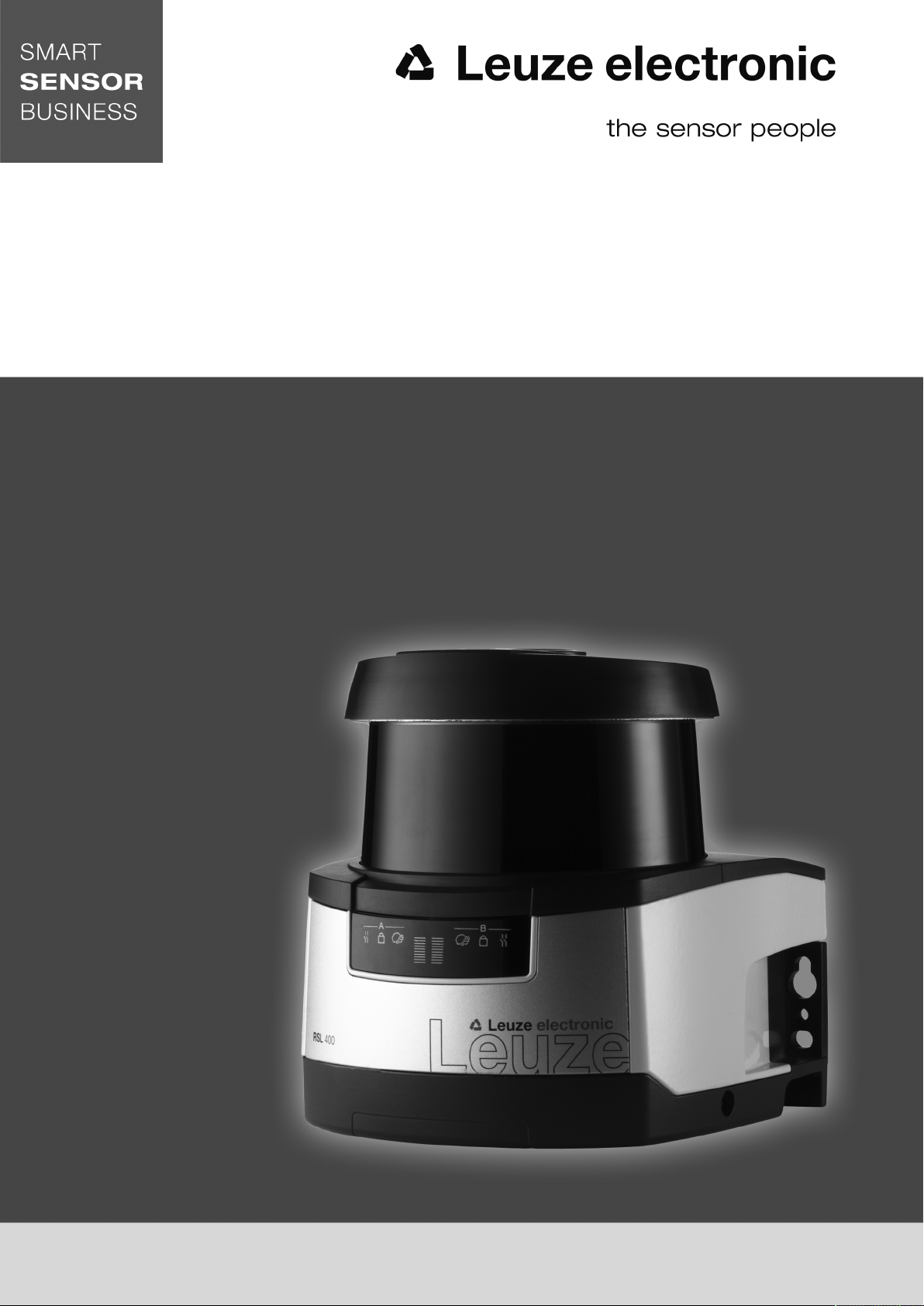
S A F E I M P L E M E N T A T I O N A N D O P E R A T I O N
O r i g i n a l o p e r a t i n g i n s t r u c t i o n s
EN 2018/03 - 50128239
We reserve the right to
make technical changes
RSL 420
RSL 425
Safety Laser Scanner
© 2018
Leuze electronic GmbH & Co. KG
In der Braike 1
D-73277 Owen / Germany
Phone: +49 7021 573-0
Fax: +49 7021 573-199
http://www.leuze.com
info@leuze.com
Leuze electronic RSL 420 2

Table of contents
Leuze electronic RSL 420 3
Table of contents
1 About this document ............................................................................................7
1.1 Other applicable documents ................................................................................................... 7
1.2 Downloading configuration software from the Internet ........................................................... 7
1.3 Used symbols and signal words .............................................................................................7
1.4 Checklists................................................................................................................................ 8
2 Safety .....................................................................................................................9
2.1 Intended use ........................................................................................................................... 9
2.1.1 Vapors, smoke, dust, particles ..........................................................................................10
2.1.2 Stray light ..........................................................................................................................10
2.1.3 Obstructions in the protective field ....................................................................................10
2.2 Foreseeable misuse ............................................................................................................. 11
2.3 Competent persons .............................................................................................................. 11
2.4 Disclaimer ............................................................................................................................. 12
2.5 Laser safety notices – Laser class1 for wavelength range outside 400-700 nm ...............12
2.6 Responsibility for safety........................................................................................................ 12
3 Device description ..............................................................................................13
3.1 Device overview.................................................................................................................... 14
3.1.1 Protective function of RSL400 safety sensors.................................................................. 14
3.1.2 Parameters for protective function ....................................................................................15
3.1.3 Device and monitoring functions .......................................................................................15
3.2 Connection unit..................................................................................................................... 15
3.3 Display elements .................................................................................................................. 16
3.3.1 LED indicator.....................................................................................................................16
3.3.2 Alphanumerical display .....................................................................................................17
3.3.3 Field-of-view display..........................................................................................................18
3.4 Mounting system (optional)................................................................................................... 18
3.5 Loop guard (optional)............................................................................................................ 18
4 Configuration and diagnostic software SensorStudio...................................19
4.1 System requirements............................................................................................................ 19
4.2 Installing software ................................................................................................................. 19
4.3 User interface........................................................................................................................ 21
4.4 FDT frame menu................................................................................................................... 22
4.4.1 Project wizard....................................................................................................................22
4.4.2 DTM change......................................................................................................................23
4.4.3 User management.............................................................................................................23
4.4.4 Exiting SensorStudio ........................................................................................................23
4.5 Using configuration projects ................................................................................................. 24
4.5.1 Selecting access level .......................................................................................................26
4.5.2 IDENTIFICATION..............................................................................................................27
4.5.3 PROCESS.........................................................................................................................27
4.5.4 CONFIGURATION ............................................................................................................27
4.5.5 DIAGNOSIS ......................................................................................................................27
4.5.6 SETTINGS ........................................................................................................................28

Table of contents
Leuze electronic RSL 420 4
5 Functions.............................................................................................................30
5.1 Authorization concept of safety sensor................................................................................. 30
5.2 Function modes of safety sensor.......................................................................................... 31
5.2.1 One protective function .....................................................................................................32
5.2.2 One protective function – four field mode.......................................................................... 32
5.3 Selectable resolution for hand, leg and body detection ........................................................ 33
5.4 Speed-dependent protective function for vehicles................................................................ 33
5.5 Response time...................................................................................................................... 33
5.6 Configurable start-up behavior ............................................................................................. 34
5.6.1 Automatic start/restart .......................................................................................................34
5.6.2 Start interlock/automatic restart......................................................................................... 34
5.6.3 Start/restart interlock (RES) ..............................................................................................35
5.7 Field pair changeover ...........................................................................................................35
5.7.1 Fixed selection of one field pair.........................................................................................36
5.7.2 Changeover of five field pairs in changeover mode Overlapped monitoring.....................36
5.7.3 Changeover of ten field pairs in changeover mode Fixed changeover moment ............... 37
5.8 Monitoring of field pair changeover....................................................................................... 38
5.9 Reference contour monitoring .............................................................................................. 39
5.10 Field pair monitoring .............................................................................................................39
5.11 EDM contactor monitoring ....................................................................................................39
5.12 E-Stop linkage ...................................................................................................................... 39
5.12.1 Contact-based safety circuit ..............................................................................................40
5.12.2 Linkage of electronic safety-related switching outputs ......................................................40
5.13 Signaling functions................................................................................................................ 40
6 Applications ........................................................................................................41
6.1 Stationary danger zone guarding.......................................................................................... 41
6.2 Stationary point of operation guarding.................................................................................. 41
6.3 Stationary access guarding .................................................................................................. 42
6.4 Mobile danger zone guarding ...............................................................................................43
6.5 Danger zone safeguarding on side-tracking skates.............................................................. 45
6.6 Vehicle navigation................................................................................................................. 46
6.6.1 Signal strength and reflector detection..............................................................................46
7 Mounting..............................................................................................................48
7.1 Basic infos............................................................................................................................. 48
7.1.1 Calculation of safety distanceS ........................................................................................48
7.1.2 Suitable mounting locations ..............................................................................................49
7.1.3 Mounting the safety sensor ...............................................................................................49
7.1.4 Mounting examples ...........................................................................................................52
7.1.5 Information on protective field dimensioning .....................................................................53
7.2 Stationary danger zone guarding.......................................................................................... 56
7.3 Stationary point of operation guarding.................................................................................. 59
7.4 Stationary access guarding .................................................................................................. 60
7.5 Mobile danger zone guarding on DTSs ................................................................................61
7.5.1 Minimum distanceD..........................................................................................................62
7.5.2 Protective field dimensions................................................................................................ 63
7.6 Mobile side guarding on DTSs.............................................................................................. 64
7.7 Mounting accessories ........................................................................................................... 64
7.7.1 Mounting system ...............................................................................................................64
7.7.2 Loop guard ........................................................................................................................65

Table of contents
Leuze electronic RSL 420 5
8 Electrical connection..........................................................................................66
8.1 Electrical supply.................................................................................................................... 66
8.2 Interfaces .............................................................................................................................. 67
8.2.1 Connection cable, control..................................................................................................67
8.2.2 Connection cable with M30 connector ..............................................................................68
8.2.3 Pin assignment of M12 Ethernet interface (communication) ( D-coded)........................... 69
8.3 Connection unit CU416......................................................................................................... 70
8.4 Circuit diagram example ....................................................................................................... 72
9 Configuring the safety sensor ...........................................................................73
9.1 Defining safety configuration ................................................................................................ 73
9.2 Connecting safety sensor to PC ...........................................................................................75
9.2.1 Connection via Ethernet cable ..........................................................................................75
9.2.2 Connection via Bluetooth ..................................................................................................75
9.2.3 Communication between safety sensor and PC ...............................................................75
9.3 Determine the configuration project...................................................................................... 76
9.4 Configuring protective function .............................................................................................77
9.4.1 Creating simple safety configuration .................................................................................78
9.4.2 Entering administration parameters ..................................................................................78
9.4.3 Activating protective function and contactor monitoring ....................................................78
9.4.4 Creating and configuring protective/warning field pairs..................................................... 78
9.4.5 Configuring field pair monitoring........................................................................................ 80
9.5 Defining permissible field pair changeovers .........................................................................81
9.6 Configuring signal outputs ....................................................................................................81
9.7 Saving configuration .............................................................................................................82
9.8 Transferring configuration project to safety sensor............................................................... 82
9.9 Selecting access level .......................................................................................................... 84
9.10 Reset safety configuration ....................................................................................................84
10 Starting up the device ........................................................................................85
10.1 Switching on ......................................................................................................................... 85
10.2 Aligning the safety sensor..................................................................................................... 85
10.3 Unlocking start/restart interlock ............................................................................................ 85
10.4 Shutting down ....................................................................................................................... 86
10.5 Restarting.............................................................................................................................. 86
10.6 Starting up replacement scanner unit ................................................................................... 86
11 Testing .................................................................................................................88
11.1 Before the initial start-up and following modifications........................................................... 88
11.1.1 Checklist for integrator – to be performed prior to the initial start-up and following modifica-
tions...................................................................................................................................88
11.2 To be performed periodically by competent persons............................................................ 90
11.3 Periodically by the operator ..................................................................................................90
11.3.1 Checklist – periodically by the operator............................................................................. 90
12 Diagnostics and troubleshooting ......................................................................92
12.1 What to do in case of failure? ...............................................................................................92
12.2 Diagnostics displays .............................................................................................................92

Table of contents
Leuze electronic RSL 420 6
13 Care, maintenance and disposal .......................................................................96
13.1 Changing scanner unit.......................................................................................................... 96
13.2 Cleaning the optics cover ..................................................................................................... 97
13.3 Servicing ............................................................................................................................... 98
13.4 Disposing .............................................................................................................................. 98
14 Service and support ...........................................................................................99
15 Technical data ...................................................................................................100
15.1 General specifications ........................................................................................................ 100
15.2 Dimensions ......................................................................................................................... 105
15.3 Dimensional drawings: Accessories ...................................................................................107
15.4 Representation of safety sensor status .............................................................................. 115
16 Standards and legal regulations .....................................................................119
17 Order guide and accessories...........................................................................120
18 EC Declaration of Conformity ..........................................................................125
About this document
Leuze electronic RSL 420 7
1 About this document
1.1 Other applicable documents
The information on the safety sensor is distributed over several documents to make working with the docu-
ments easier. You will find the documents and software for the safety sensor in the following table:
Purpose and target group of the document Document/software ti-
tle
Source
Software for users of the machine
a)
for safety sen-
sor diagnostics if a fault occurs and for machine de-
sign engineers for configuring the safety sensor
SensorStudio
DTM RSL400
Supplied with the safety
sensor on data carrier
Notes for the machine design engineer
a)
"Safe implementation
and operation"
(this document)
PDF, supplied with the
safety sensor on data
carrier
Notes for the machine design engineer
a)
for config-
uring the safety sensor (software instructions)
Online help for software Supplied with the safety
sensor on data carrier
Notices regarding mounting, alignment and connec-
tion of the safety sensor
"Quick Start Guide
RSL400"
Print document, supplied
with the safety sensor
a) Machine identifies the product that the safety sensor is installed in.
1.2 Downloading configuration software from the Internet
Ä Call up the Leuze home page: www.leuze.com.
Ä Enter the type designation or part number of the device as the search term.
Ä The configuration software can be found on the product page for the device under the Downloads tab.
1.3 Used symbols and signal words
Tab.1.1: Warning symbols and signal words
Symbol indicating dangers to persons
Symbol indicating dangers from harmful laser radiation
Symbol indicating possible property damage
NOTE Signal word for property damage
Indicates dangers that may result in property damage if the measures for dan-
ger avoidance are not followed.
CAUTION Signal word for minor injuries
Indicates dangers that may result in minor injury if the measures for danger
avoidance are not followed.
WARNING Signal word for serious injury
Indicates dangers that may result in severe or fatal injury if the measures for
danger avoidance are not followed.
DANGER Signal word for life-threatening danger
Indicates dangers with which serious or fatal injury is imminent if the measures
for danger avoidance are not followed.

About this document
Leuze electronic RSL 420 8
Tab.1.2: Other symbols
Symbol for tips
Text passages with this symbol provide you with further information.
Symbol for action steps
Text passages with this symbol instruct you to perform actions.
Symbol for action results
Text passages with this symbol describe the result of the preceding action.
Tab.1.3: Terms and abbreviations
CS Switching signal from a control
(Controller Signal)
DTM Software device manager of the safety sensor
(Device Type Manager)
EDM Contactor monitoring
(External Device Monitoring)
FDT Software frame for management of device managers (DTM)
(Field Device Tool)
Field pair A protective field with an associated warning field
DTS Driverless Transportation System
LED LED, display element in the safety sensor
(Light Emitting Diode)
OSSD Safety-related switching output
(Output Signal Switching Device)
PFH
d
Probability of a dangerous failure per hour
(Probability of dangerous Failure per Hour)
PL Performance Level
Quad Two field pairs (four fields) that are monitored simultaneously in four field mode
TSS Transverse Side-tracking Skate
RES Start/restart interlock
(Start/REStart interlock)
SIL Safety Integrity Level
State ON: device intact, OSSDs switched on
OFF: device intact, OSSDs switched off
Locking: device, connection or control/operation faulty, OSSDs switched off
(lock-out)
1.4 Checklists
The checklists serve as a reference for the machine manufacturer or supplier (see chapter 11 "Testing").
They replace neither testing of the complete machine or system prior to the initial start-up nor their periodic
testing by a competent person. The checklists contain minimum testing requirements. Depending on the
application, other tests may be necessary.
Safety
Leuze electronic RSL 420 9
2 Safety
Before using the safety sensor, a risk assessment must be performed according to valid standards (e.g.
ENISO12100, ENISO13849-1, IEC61508, ENIEC62061). The result of the risk assessment determines
the required safety level of the safety sensor (see chapter 15.1 "Safety-relevant technical data"). For
mounting, operating and testing, this document as well as all applicable national and international stan-
dards, regulations, rules and directives must be observed. Relevant and supplied documents must be ob-
served, printed out and handed to affected persons.
Ä Before working with the safety sensor, completely read and observe the documents applicable to your
task.
In particular, the following national and international legal regulations apply for the commissioning, techni-
cal inspections and work with safety sensors:
• Machinery directive 2006/42/EC
• Low voltage directive 2006/95/EC
• EMC directive 2004/108/EC
• Use of work equipment directive 89/655/EEC supplemented by directive 95/63EC
• OSHA 1910 Subpart O
• Safety regulations
• Accident-prevention regulations and safety rules
• Ordinance on Industrial Safety and Health and employment protection act
• Product Safety Law (ProdSG)
NOTICE
For safety-related information you may also contact local authorities (e.g., industrial inspec-
torate, employer's liability insurance association, labor inspectorate, occupational safety and
health authority).
2.1 Intended use
The safety sensor protects persons or body parts at points of operation, danger zones or access points of
machines and systems.
WARNING
A running machine may result in serious injury!
Ä Make certain that the safety sensor is correctly connected and that the protective function of
the protective device is ensured.
Ä Make certain that, during all conversions, maintenance work and inspections, the system is
securely shut down and protected against being restarted.
• The safety sensor may only be used after it has been selected in accordance with the respectively ap-
plicable instructions and relevant standards, rules and regulations regarding labor protection and safety
at work, and after it has been installed on the machine, connected, commissioned, and checked by a
competent person (see chapter 2.3 "Competent persons").
• When selecting the safety sensor it must be ensured that its safety-related capability meets or exceeds
the required Performance Level PL
r
ascertained in the risk assessment (see chapter 15.1 "Safety-rele-
vant technical data").
• The safety sensor may only be used in North America in applications that satisfy the requirements
specified by NFPA79.
• With the “access guarding” function, the safety sensor detects persons only when they enter the danger
zone but cannot tell whether there are any persons inside the danger zone. For this reason, a start/
restart interlock in the safety chain is essential in this case.
• The construction of the safety sensor must not be altered. When manipulating the safety sensor, the
protective function is no longer guaranteed. Manipulating the safety sensor also voids all warranty
claims against the manufacturer of the safety sensor.
Safety
Leuze electronic RSL 420 10
• The safety sensor must be inspected regularly by a competent person to ensure proper integration and
mounting (see chapter 15.1 "Safety-relevant technical data").
• The safety sensor must be exchanged after a maximum of 20 years. Repairs or the exchange of wear
parts do not extend the mission time.
CAUTION
Observe intended use!
The protection of personnel and the device cannot be guaranteed if the device is operated in a
manner not complying with its intended use.
Ä Only operate the device in accordance with its intended use.
Ä LeuzeelectronicGmbH+Co.KG is not liable for damages caused by improper use.
Ä Read these operating instructions before commissioning the device. Knowledge of the oper-
ating instructions is an element of proper use.
NOTICE
Comply with conditions and regulations!
Ä Observe the locally applicable legal regulations and the rules of the employer's liability insur-
ance association.
2.1.1
Vapors, smoke, dust, particles
Vapors, smoke, dust and all particles visible in the air can cause the machine to switch off unintentionally.
This can mislead the user into bypassing the safety devices.
Ä Do not use the safety sensor in environments in which heavy vapors, smoke, dust or other visible parti-
cles occur at the beam level.
2.1.2
Stray light
Light sources can impair the safety sensor's availability. Interfering light sources are:
• Infrared light
• Fluorescent light
• Strobe light
Ä Ensure that there are no interfering light sources at beam level.
Ä Prevent reflective surfaces at beam level.
Ä Where applicable, take protective field addition distances into account.
Ä Implement all additional measures to ensure that any special application of any effected beam types
does not impair the safety sensor's operation.
2.1.3
Obstructions in the protective field
Ä Do not bring any additional window materials into the area monitored by the safety sensor.
NOTICE
No screen between optics cover and monitoring area!
Ä Between the optics cover of the safety sensor and the monitored area, no further screen
may be mounted to protect the safety sensor.
Safety
Leuze electronic RSL 420 11
2.2 Foreseeable misuse
Any use other than that defined under "Intended use" or which goes beyond that use is considered im-
proper use.
In principle, the safety sensor is not suitable as a protective device for use in the following cases:
• Danger posed by ejected objects or the spraying of hot or hazardous liquids from within the danger
zone.
• Applications in explosive or easily flammable atmospheres.
• Use for outdoor applications or under extreme temperature fluctuations.
Humidity, condensation and other weather influences can impair the protective function.
• Use on vehicles with combustion engines.
Alternators and ignition systems can cause EMC interferences.
NOTICE
Do not modify or otherwise interfere with the safety sensor!
Ä Do not carry out modifications or otherwise interfere with the safety sensor. The safety sen-
sor must not be tampered with and must not be changed in any way.
Ä The safety sensor must not be opened. There are no user-serviceable parts inside.
Ä The construction of the safety sensor must not be altered. When manipulating the safety
sensor, the protective function is no longer guaranteed.
Ä Manipulating the safety sensor voids all warranty claims against the manufacturer of the
safety sensor.
Ä Repairs must only be performed by Leuze electronic GmbH + Co. KG.
2.3 Competent persons
Connecting, mounting, commissioning and adjustment of the safety sensor must only be carried out by
competent persons.
Prerequisites for competent persons:
• They have a suitable technical education.
• They know the rules and regulations for labor protection, safety at work and safety technology and can
assess the safety of the machine.
• They know the operating instructions for the safety sensor and the machine.
• They have been instructed by the responsible person on the mounting and operation of the machine
and of the safety sensor.
• They perform a task related to the subject matter shortly thereafter and keep their knowledge up to date
through continuous further training.
Certified electricians
Electrical work must be carried out by a certified electrician.
Due to their technical training, knowledge and experience as well as their familiarity with relevant standards
and regulations, certified electricians are able to perform work on electrical systems and independently de-
tect possible dangers.
In Germany, certified electricians must fulfill the requirements of accident-prevention regulations DGUV
Regulation3 (e.g. electrician foreman). In other countries, there are respective regulations that must be ob-
served.

Safety
Leuze electronic RSL 420 12
2.4 Disclaimer
LeuzeelectronicGmbH+Co.KG is not liable in the following cases:
• The safety sensor is not used as intended.
• Safety notices are not adhered to.
• Reasonably foreseeable misuse is not taken into account.
• Mounting and electrical connection are not properly performed.
• Proper function is not tested (see chapter 11 "Testing").
• Changes (e.g., constructional) are made to the safety sensor.
2.5 Laser safety notices – Laser class1 for wavelength range outside 400-700 nm
NOTICE
Additional measures for shielding the laser radiation are not necessary (safe for eyes).
WARNING
LASER RADIATION – LASER CLASS 1
The device satisfies the requirements of IEC60825-1:2007 (EN60825-1:2007) safety regula-
tions for a product of laser class1 as well as the FDA Radiation Performance Standards,
21CFR, SubchapterJ, Part1010 and Part1040 with deviations corresponding to "Laser Notice
No.50" from June 24, 2007.
Ä Observe the applicable statutory and local laser protection regulations.
Ä The device must not be tampered with and must not be changed in any way.
There are no user-serviceable parts inside the device.
Ä Repairs must only be performed by Leuze electronic GmbH + Co. KG.
2.6 Responsibility for safety
Manufacturer and operator must ensure that the machine and implemented safety sensor function properly
and that all affected persons are adequately informed and trained.
The type and content of all imparted information must not lead to unsafe actions by users.
The manufacturer of the machine is responsible for:
• Safe machine construction
• Safe implementation of the safety sensor, verified by the initial test performed by a competent person
• Imparting all relevant information to the operating company
• Adhering to all regulations and directives for the safe commissioning of the machine
The operator of the machine is responsible for:
• Instructing the operator
• Maintaining the safe operation of the machine
• Adhering to all regulations and directives for labor protection and safety at work
• Regular testing by competent persons
Device description
Leuze electronic RSL 420 13
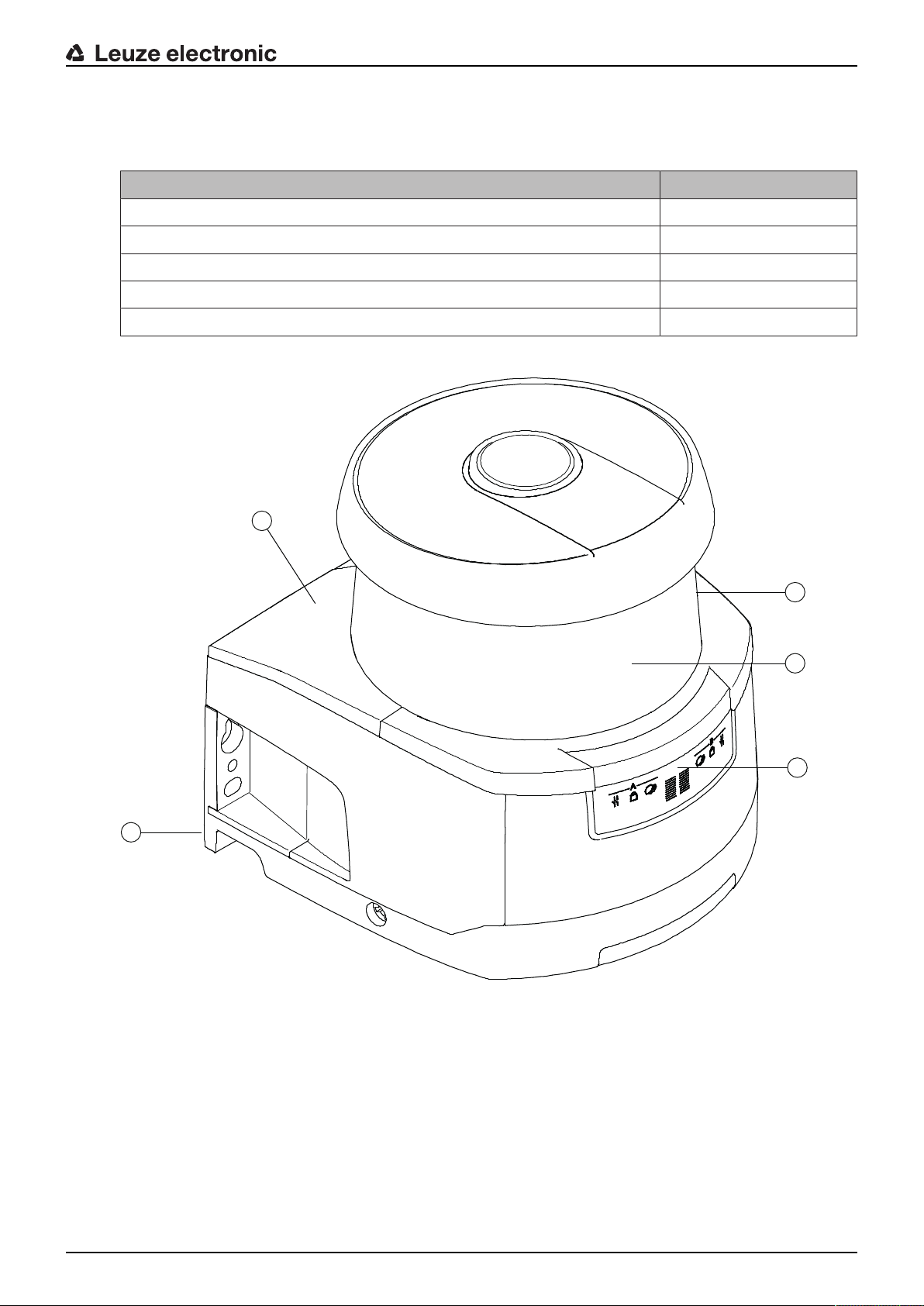
3 Device description
The safety sensors from the RSL400 series are optoelectronic, two-dimensional measuring safety laser
scanners. They satisfy the following standards:
RSL400
Type in accordance with IEC/EN61496 3
Category in accordance with ENISO13849 3
Safety Integrity Level (SIL) in accordance with IEC61508 2
SILCL in accordance with IEC/EN62061 2
Performance Level (PL) in accordance with ENISO13849‑1 d
1
2
4
5
3
1 Scanner unit
2 Connection unit
3 Optics cover
4 Alphanumerical display (displayed)
5 LED indicators
Fig.3.1: Device overview of RSL400 safety laser scanners
Device description
Leuze electronic RSL 420 14
All safety sensors of the RSL420 series are equipped as follows:
• Laser scanner with the range class S, M, L or XL:
Operating range
class
Operating range [m]
S 3.00
M 4.5
L 6.25
XL 8.25
• 24-digit alphanumerical display
• Integrated electronic spirit level for aligning the safety sensor
• LED indicator
• Connection unit:
• Configuration memory
• Ethernet connection for communication and configuration with the PC/laptop
• Electrical connection to the machine via connection cable
3.1 Device overview
The following table provides an overview of the possible uses, features and functions of the RSL400 safety
sensors.
Tab.3.1: Device overview
RSL410 RSL420
RSL425
RSL430 RSL440
RSL445
Stationary danger zone guarding x x x x
Mobile danger zone guarding x x x x
Access guarding x x x x
Point of operation guarding x x x x
Safety-related switching outputs
Protective functionA
Protective functionB
1 OSSD pair
x
-
1 OSSD pair
x
-
2 OSSD pairs
x
x
2 OSSD pairs
x
x
Signal outputs Up to 3 Up to 4 Up to 9 Up to 9
Configurable signal outputs x x x x
Number of changeover-capable pro-
tective/warning field pairs
1 10 10+10 100
E-stop linkage - x x x
Four field mode (quads) x x x x
Internal safe time delay - - x x
Measurement data output optimized
for vehicle navigation
- Only RSL425 - Only RSL445
3.1.1
Protective function of RSL400 safety sensors
The safety sensor transmits periodic light pulses via a rotating deflection unit. The light pulses are scattered
in all directions by obstacles, e.g. persons. A part of the light pulses is received again by the safety sensor
and evaluated. The safety sensor calculates the precise position of the object from the propagation time of
the radiated light and the current angle of the deflection unit at that time. If the object is within a predefined
area, the protective field, the safety sensor performs a safety-related switching function. It switches the
safety-related switching outputs off.
Device description
Leuze electronic RSL 420 15
Only when the protective field is free again does the safety sensor reset the safety-related switching func-
tion, either automatically or following acknowledgment, depending on the operating mode.
The safety sensor can even detect people when they are wearing very dark clothes, which have a very
weak diffuse reflectance.
3.1.2
Parameters for protective function
The following parameters for switching off the safety-related switching outputs of the safety sensor are
taken into consideration for the protective function:
• Configurable protective fields
• Reference contour of protective fields
• Configurable field pair changeover
• Selectable resolution for hand, leg or body detection
• Safety sensor response time
• Selectable start-up behavior
The following non-safety-oriented functions and signals also belong to the protective function:
• Configurable warning fields
• Configurable indication signals
Additional functions of the protective function
• Warning field evaluation
• Selectable dynamic contactor monitoring (EDM)
• E-Stop
3.1.3
Device and monitoring functions
• Monitoring and release of field pair changeover
3.2 Connection unit
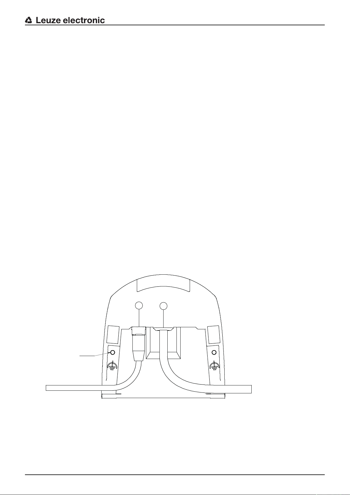
The safety sensor is mounted, connected and aligned using the connection unit.
M5 2x
2
1
1 Connection cable, connection to the machine
2 M12 socket, D-coded, Ethernet communication connection
M5 Connection for functional earth with M5x10 self-cutting/self-tapping (gas tightness) and ground strap
Fig.3.2: Device overview, connection unit

Device description
Leuze electronic RSL 420 16
Functions of connection unit:
• Attachment point for mounting, either directly or using an optional mounting system.
When devices are swapped out, the connection unit remains mounted and aligned.
• EMC wiring for signal inputs/outputs and supply using connection cable
Safety sensor Connection unit Connection
RSL420 CU416-y
y=5000, 10000, 25000
Connection cable, 16-wire
5m, 10m, 25m
• Connector bushing and EMC for the Ethernet TCP/IP communication and configuration interface to the
PC/laptop
• Memory for the configuration files and automatic parameter transfer in the event of device swap-out
• Quick-release connection to the scanner unit (see Quick Start Guide) for easy device swap-out
3.3 Display elements
The display elements of the safety sensors simplify start-up and fault analysis.
3.3.1
LED indicator
Located on the connection unit are the LEDs for displaying the operating state.
• Protective function A: LEDs 1, 2, 3
1
2 3 4 5 6
Tab.3.2: Meaning of the LEDs
LED Color State Description
1 Red/green OFF Device switched off
Red OSSD off
Red, flashing Error
Green OSSD on
2 Yellow OFF RES deactivated
RES activated and enabled
Flashing Protective field occupied
ON RES activated and blocked but ready to be unlocked
Protective field free and linked sensor enabled (if applicable)
3 Blue OFF Free warning field
ON Warning field interrupted
4 Blue OFF Four field mode: warning field3 free
ON Four field mode: warning field3 interrupted
5 Yellow Flashing Four field mode: warning field2 interrupted
Device description
Leuze electronic RSL 420 17
3.3.2
Alphanumerical display
In normal operation, the 24-digit alphanumerical display of the safety sensor shows the monitored protec-
tive and warning field pairs. It also provides assistance during detailed error diagnostics (see chapter 12
"Diagnostics and troubleshooting").
Tab.3.3: Alphanumerical displays
Display Description Example
Upon startup without configuration/upon initial commissioning
Sensor type Sensor type 420M
Sensor serial number Sensor serial number SN: 21513123456
Sensor name / Network name Name of the sensor / network A123456789
Configuration necessary Configuration required CONFIG REQUESTED
Repeated until end of booting phase / start phase, then
Spirit level permanent Horizontal alignment in degrees: H
Vertical alignment in degrees: V
H -3° V +9°
Upon startup with configuration
Sensor type Sensor type 410XL
Sensor serial number Sensor serial number SN: 21513123456
Sensor name / Network name Name of the sensor / network A123456789
IP: DHCP/FIX DHCP or permanent IP address IP: DHCP or
10.25.45.2
Bluetooth on/off Bluetooth detection ON/OFF Bluetooth ON
Date of configuration Date of configuration 11/13/2014 08:15
Signature Signature of configuration DG45L8ZU
Level Horizontal alignment in degrees: H
Vertical alignment in degrees: V
H-3° V+9°
Repeated until end of booting phase / start phase, then
Display following configuration of normal operation
e.g. display of active field pair A1.1
Transfer of the configuration data
AWAITING CONFIG Until downloading of configuration data is confirmed
DOWNLOAD CONFIG During transfer of configuration data
Level
H +/- ..° V +/- .. ° Horizontal alignment in degrees: H
Vertical alignment in degrees: V
H -3° V +9°
Sensor detection
PING received Display for identification by device
name
PING received Device name
Message
Message via a signal output or diag-
nosis ID
ProtF A: E123
Device: P007 - wrong Config
Device description
Leuze electronic RSL 420 18
Display Description Example
Error diagnostics
F… Failure, internal device error
E… Error, external error
U… Usage info, application error
I… Information
P… Parameter, inconsistency in the con-
figuration
For error diagnostics, the error's respective letter is displayed first followed by the number code. An Au-
toReset is carried out after 10 seconds for errors that do not cause locking, with an unauthorized restart be-
ing impossible. In the case of blocking errors, the voltage supply must be separated and the cause of the
error must be eliminated. Before switching on again, the steps taken before initial commissioning must be
repeated (see chapter 10 "Starting up the device").
When the protective field has been free for about 5 seconds, the device switches back to the display in nor-
mal operation.
Displays in normal operation
The display in normal operation depends on the operating state of the safety sensor. The display can be
switched off or rotated by 180° by means of the software.
3.3.3
Field-of-view display
The upper and lower limit of the safety sensor's field of view can be displayed by means of horizontal lines
on the optics cover.
Ä Make sure that the safety sensor's field of view is always completely unobstructed.
NOTICE
Always check the protective field configuration!
Ä Check all defined protective fields each time the configuration is changed.
The field-of-view display is a comfort function and is not intended as a substitute for check-
ing the protective field configuration.
Ä The safety sensor's field of view must be completely unobstructed on the application side.
3.4 Mounting system (optional)
Mounting systems and mounting brackets simplify mounting and alignment of the safety sensor. Mounting
systems and mounting brackets are available as accessories (see chapter 17 "Order guide and acces-
sories").
3.5 Loop guard (optional)
The loop guard for the optics cover prevents damage to the safety sensor caused by light contact with for-
eign objects. The loop guard is available as an accessory (see chapter 17 "Order guide and accessories").
Configuration and diagnostic software SensorStudio
Leuze electronic RSL 420 19
4 Configuration and diagnostic software SensorStudio
To start up a safety sensor in your application, the safety sensor must be set up according to its specific
use using the configuration and diagnostic software. The software is used to set up the safety configuration
of the safety sensor, to change the communication and diagnostics settings and to perform diagnostic rou-
tines. Communication takes place via the PC.
The software is designed according to the FDT/DTM concept:
• You make the individual configurations for the safety sensor in the Device Type Manager (DTM).
• The individual DTM configurations of a project can be called up via the frame application of the Field
Device Tool (FDT).
• Each device DTM has a communication DTM that sets up and monitors the communication connec-
tions to the sensor.
NOTICE
Only use the software for safety sensors manufactured by Leuze electronic.
4.1 System requirements
To use the software, you need a PC or laptop with the following specifications:
Hard disk space At least 250MB free memory
If you want to save the protective field or configuration values, you will
need more memory.
Screen display Color
External drive DVD drive
Input device Keyboard and mouse or touchpad
Output device Printer (black-white or color)
Interfaces RJ45 Ethernet network
Bluetooth (optional) - If the PC does not have integrated Bluetooth technol-
ogy, use an appropriate USB or PCMCIA adapter if necessary.
Operating system Microsoft® Windows7 and Windows8.1
NOTICE
Only the term "PC" is used below.
4.2 Installing software
Prerequisites:
• You do not need the safety sensor to install the software on the PC.
• All Windows applications are closed.
NOTICE
The software is installed in two steps:
Ä Installing the SensorStudio FDT frame.
Ä Installing LeSafetyCollection device manager (DTM).
Configuration and diagnostic software SensorStudio
Leuze electronic RSL 420 20
Installing the SensorStudio software
NOTICE
If FDT frame software is already installed on your PC, you do not need the SensorStudio instal-
lation.
You can install the device manager (DTM) in the existing FDT frame.
Ä Insert the data carrier.
ð The installation will start automatically.
Ä If installation does not start automatically, double-click the file SensorStudioSetup.exe.
Ä If you want to call up the menu of the CD, double-click the file start.exe.
Ä Select a language for the interface text in the installation wizard and software and confirm with [OK].
ð The installation wizard starts.
Ä Click [Next].
ð The installation wizard opens the software license agreement.
Ä If you want to accept the license agreement, select the appropriate option field and click [Next].
Ä If the suggested installation path is OK, click [Next].
If you want to specify a different path, click the [Browse] button. Select a different path, confirm with
[OK] and click [Next].
Ä Click the [Install] button to start installation.
ð The wizard installs the software and places a shortcut on the desktop ( ).
Ä Click the [Finish] button to complete installation.
Installing LeSafetyCollection device manager (DTM)
Prerequisites:
• The Sensor Studio software is installed on the PC.
• Data carrier inserted.
Ä Double-click the file LeSafetyCollectionSetup.exe.
Ä Select a language for the interface text in the installation wizard and software and confirm with [OK].
ð The installation wizard starts.
Ä Click [Next].
ð The installation wizard opens the software license agreement.
Ä If you want to accept the license agreement, select the appropriate option field and click [Next].
Ä If the suggested installation path is OK, click [Next].
If you want to specify a different path, click the [Browse] button. Select a different path, confirm with
[OK] and click [Next].
Ä Click the [Install] button to start installation.
ð The wizard installs the software.
Ä Click the [Finish] button to complete installation.
NOTICE
During installation of the software, a user admin (without password query) is created so that you
can start the software without user identification. If other users are registered (Tools > User
management in the FDT frame menu), you must log in at the software with a user name and
password.
This setting allows you to connect to the safety sensor and to read out, upload, enter or change
the safety configuration and all settings using the RSL400 device DTM. The password for the
safety sensor only needs to be entered (i.e. the access level only needs to be changed) when
the changes are downloaded to the safety sensor (see chapter 4.5.1 "Selecting access level").

Configuration and diagnostic software SensorStudio
Leuze electronic RSL 420 21
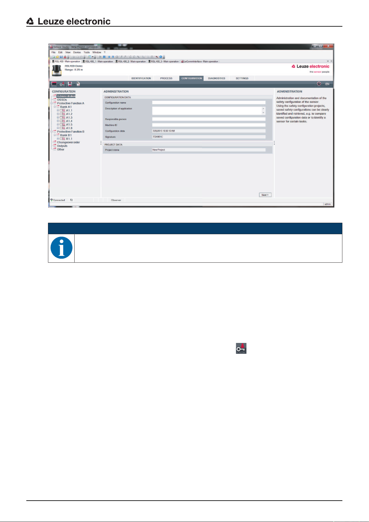
4.3 User interface
2 3
4
5
1
6
7
1 FDT frame menu with toolbar
2 RSL400 device manager (DTM)
3 Navigation tabs
4 Information area
5 Dialog box
6 Status line
7 Navigation area
Fig.4.1: User interface of the software
FDT frame menu
The device managers (DTM) of the safety sensors are created and managed in the FDT frame menu.
Device manager DTM
Configuration projects for setting up the selected safety sensor are created and managed in the device
managers (DTM) of the safety sensors.

Configuration and diagnostic software SensorStudio
Leuze electronic RSL 420 22
Project tree view
21
3
1 FDT frame menu
2 Device manager (DTM) tabs
3 Project tree view
Fig.4.2: User interface with project tree view
The project tree view shows the structure of the currently installed device managers (DTM). In the project
tree view you can, for example, add copies of an already configured device manager (DTM) quickly and
easily to the DTM structure if you want to operate multiple safety sensors with the same configuration set-
tings.
Example: DTS with safety sensors on front and rear side
4.4 FDT frame menu
NOTICE
You can find complete information on the FDT frame menu in the online help system. Select the
Help menu item in the menu [?].
4.4.1
Project wizard
Using the Project Wizard you can create and change configuration projects for setting up the safety sensor
(see chapter 4.5 "Using configuration projects").
Ä Start the Project Wizard in the FDT frame menu by clicking the button.
NOTICE
Information on the Project Wizard can be found in the online help for the FDT frame menu under
Sensor Studio Options.
Configuration and diagnostic software SensorStudio
Leuze electronic RSL 420 23
4.4.2
DTM change
The DTM Change function makes it easier for you to call up the communication DTM of a device or change
from device DTM to communication DTM.
Ä Start the DTM change function in the FDT frame menu by clicking the button.
NOTICE
Information on DTM change can be found in the online help for the FDT frame menu under Sen-
sor Studio Options.
4.4.3
User management
Using the user management in the FDT frame menu, you can create users, log users in/out and manage
passwords.
Creating users
When creating a user in the user management via Tools > User management in the software frame
menu, select the access level for the user. For information on access permissions and access levels (see
chapter 5.1 "Authorization concept of safety sensor").
Ä In the FDT frame menu, click Tools > User management > Create user.
Logging users in/out
Prerequisites:
• Users have been created
Ä In the FDT frame menu, click Tools > Log in/log out.
Managing passwords
Prerequisites:
• Users have been created
Ä In the FDT frame menu, click Tools > Change password.
NOTICE
Password management via the FDT frame menu applies to all installed device managers (DTM)
of the project.
Whenever write access occurs, the safety sensors of the RSL400 series always check the ac-
cess level (Engineer, Expert) and the password defined via the device manager (DTM) (SET-
TINGS > Passwords) independently of the password management via the FDT frame menu.
4.4.4
Exiting SensorStudio
When you have finished making the configuration settings, close the configuration and diagnostics soft-
ware.
Ä Exit the program via File > Exit.
Ä Save the configuration settings as a configuration project on the PC.
You can open the configuration project again at later time via File > Open or with the SensorStudio Project
Wizard ( ).
Configuration and diagnostic software SensorStudio
Leuze electronic RSL 420 24
4.5 Using configuration projects
Configuration projects are created and managed in the device manager (DTM) of the selected safety sen-
sor.
NOTICE
During installation of the software, a user admin (without password query) is created so that you
can start the software without user identification. If other users are registered (Tools > User
management in the FDT frame menu), you must log in at the software with a user name and
password.
This setting allows you to connect to the sensor and to read out, upload, enter or change the
safety configuration and all settings using the RSL400 device DTM. The password for the sen-
sor only needs to be entered (i.e. the access level only needs to be changed) when the changes
are downloaded to the safety sensor (see chapter 4.5.1 "Selecting access level").
Ä Start the configuration and diagnostics software on the PC by double-clicking the button.
ð The mode selection of the Project Wizard is displayed.
ð If the mode selection is not shown, start the Project Wizard in the FDT frame menu by clicking the
[Project Wizard] button ( ).
Fig.4.3: Project wizard
Ä Select the configuration mode and click [Next].
ð Automatic connection to a connected safety sensor (Online)
ð Device selection without communication connection (offline)
ð Load a saved project again
ð The project wizard displays the SEARCH DEVICES dialog box.
Ä Select the interface and click the [Start] button.
Configuration and diagnostic software SensorStudio
Leuze electronic RSL 420 25
Ä Find the safety sensor for your configuration project using the search function of the communication
DTM.
21
3
4
1 FDT frame menu
2 Communication DTM
3 Device list
4 Search function
Fig.4.4: Communication DTM with search function
ð The project wizard displays the device list of configurable safety sensors in the SEARCH DEVICES di-
alog box.
Fig.4.5: Device selection in project wizard
Ä Select the safety sensor from the device selection list and click [Next].
ð The device manager (DTM) of the safety sensor shows the initial screen for the configuration project.
Configuration and diagnostic software SensorStudio
Leuze electronic RSL 420 26
Fig.4.6: Initial screen for safety configuration
NOTICE
The device manager (DTM) starts without querying the access level of the user. During commu-
nication with the safety sensor, the safety sensor does however query the access level of the
user. To change the access levels (see chapter 4.5.1 "Selecting access level").
Setting device manager
Using the menus of the device manager (DTM) you can set the parameters of the safety configuration. The
online help system provides information on the menu items and adjustment parameters. Select the Help
menu item in the menu [?].
4.5.1
Selecting access level
Using the device manager you can change the access level of the user if necessary.
For the authorization concept of the software, see chapter see chapter 5.1 "Authorization concept of safety
sensor".
Ä Click in the DTM menu bar on the [Change access level]button ( ).
ð The Change access level dialog box opens.
Ä In the Access level list, select the item Expert, Engineer or Observer and enter the default password or
the password defined for the individual user.
The following access levels are available:
• Observer can read everything (no password)
• Expert can change communication and diagnostics settings (default password = comdiag)
• Engineer can additionally change the safety configuration (default password = safety)
The password is case-sensitive (i.e. a distinction is made between upper-case and lower-case letters).
Ä Confirm with [OK].
Configuration and diagnostic software SensorStudio
Leuze electronic RSL 420 27
4.5.2
IDENTIFICATION
Detailed information on the menu items and setting parameters can be found in the information area and in
the online help. Select the Help menu item in the menu [?].
• RSL400 safety laser scanner
• Sensor and configuration data
• Technical data
4.5.3
PROCESS
Detailed information on the menu items and setting parameters can be found in the information area and in
the online help. Select the Help menu item in the menu [?].
• Sensor display
Device display in the DTM menu
• SENSOR DISPLAY
• STATE OF THE ACTIVE PROTECTIVE AND WARNING FIELDS
• SENSOR DATA
• Measurement contour
• Inputs / outputs
• SENSOR DISPLAY
• CONNECTIONS AND SIGNALS
• Simulation – only with access level Engineer
• Measurement contour
• Inputs / outputs
4.5.4
CONFIGURATION
see chapter 9 "Configuring the safety sensor"
NOTICE
You can only transfer changes made in the CONFIGURATION menu to the safety sensor if you
are logged in with the access level Engineer.
4.5.5
DIAGNOSIS
Adjustment / Alignment
Display of safety sensor alignment using the integrated electronic spirit level
Prerequisites: The software and safety sensor are connected.
Ä In the DIAGNOSIS menu, click the [Align sensor mechanically]button ( ).
ð The safety sensor display shows the horizontal and vertical alignment in degrees.
Visually identify device
If you have installed multiple safety sensors, identify the safety sensor that is connected to the currently
open device manager (DTM).
Prerequisites: The software and safety sensor are connected.
Ä In the DIAGNOSIS menu, click the [Visually identify sensor]button ( ).
ð In the display of the safety sensor connected to the device manager (DTM), the message "PING re-
ceived" flashes for ten seconds.
Reset sensor
Acknowledge messages and faults
Set safety sensor to safety mode
Configuration and diagnostic software SensorStudio
Leuze electronic RSL 420 28
Create and save service file
The service file contains all available information on the safety sensor as well as configuration and settings.
When requesting support, send the service file to the Leuze electronic customer service (see chapter 14
"Service and support").
Sensor display
Device display in the DTM menu
• SENSOR DISPLAY
• STATE OF THE ACTIVE PROTECTIVE AND WARNING FIELDS
• SENSOR DATA
Diagnostics list
Access list
EventLog
4.5.6
SETTINGS
NOTICE
You can only transfer changes made in the SETTINGS menu to the safety sensor if you are
logged in with the access level Engineer.
Communication
• LAN
• DHCP
• CONNECTION SETTINGS
• MAC address
• Bluetooth
• Activate Bluetooth module
• Activate device scan
• Bluetooth address
EventLog
Trigger signals output when certain events occur, are recorded and shown in the event list of the safety
sensor.
Information on the monitored signals can be found in the information area and in the online help. Select the
Help menu item in the menu [?].
Sensor display
Activation of the safety sensor alphanumerical display.
Information on the display options can be found in the information area and in the online help. Select the
Help menu item in the menu [?].
Passwords
NOTICE
If a user has forgotten his password for login at the safety sensor or has repeatedly entered the
password incorrectly, he cannot log in at the safety sensor. The CHANGE PASSWORD function
is therefore not available.
To reset the password, a user must generate a reset password and have it confirmed by the
manufacturer.

Configuration and diagnostic software SensorStudio
Leuze electronic RSL 420 29
CHANGE PASSWORD
Ä Define individual passwords for the access levels Engineer and Expert. These passwords replace the
default passwords set by the manufacturer.
The password is case-sensitive (i.e. a distinction is made between upper-case and lower-case letters).
Reset password
Prerequisites:
• The software is connected to the safety sensor.
Ä Generate a one-time password.
Note down the generated reset password.
Ä Send the reset password to the Leuzeelectronic customer service for confirmation (see chapter 14
"Service and support").
The device can now be switched off and the connection can be terminated.
Ä Enter the confirmed reset password and create a new password.
Optics cover
• Monitoring of optics cover
• Dialog box for calibrating a replacement optics cover
Field editor display options
Display settings for the field editor when defining protective/warning fields.
• CONTOUR ALIGNMENT
• COORDINATE DISPLAY
• EDITOR BEHAVIOR
Information on the display options can be found in the information area and in the online help. Select the
Help menu item in the menu [?].
Functions
Leuze electronic RSL 420 30
5 Functions
The functions of the safety sensor must be matched to the respective application and its safety require-
ments. You can activate/deactivate the functions and adapt them using parameters. You configure the
functions with the help of the configuration and diagnostics software (see chapter 9 "Configuring the safety
sensor").
• You configure the functions of the safety sensor in the software as configuration projects.
• In each configuration project you determine the protective function and the configurable field pairs via
the selected function mode.
• The changeover-capable protective/warning field pairs for the selected function mode are defined in
configuration banks.
• You determine the resolution, the start-up behavior, the response time and, where applicable, the vehi-
cle speed together for all protective/warning field pairs of a configuration bank.
5.1 Authorization concept of safety sensor
User management allows target-group-oriented communication between the software and the safety sen-
sor. Which functions are available depends on the selected access level of the user. For information on
the software and on user management (see chapter 4 "Configuration and diagnostic software SensorStu-
dio").
• Changing the safety configuration as well as the communication and diagnostics settings of the sensor
is only permitted for certain access levels.
• Installation and operation of the software do not depend on the access level of the user.
The following access levels are available:
Tab.5.1: Access levels and functions available
Access level Functions
Observer • Display the measurement contour
• Upload and display configuration data from the safety sensor
• Display status information from the safety sensor
• Display diagnostics list
• Customize display
• Display and evaluate the measurement contour
• Load configuration data from the safety sensor
• Load status information from the safety sensor
• Display diagnostics list
• Create service file
• Reset password
Expert In addition to the functions of the Observer
• Load the signed safety configuration from a file and transfer/download to
the safety sensor
• Transfer changed communication and diagnostics settings from the PC
to the safety sensor
• Print configuration data incl. protective/warning fields
• Calibrate optics cover
Loading...