


 Loading...
RS4soft
Configuration and diagnostics software for ROTOSCAN RS4 Safety Laser Scanner
| <![if ! IE]> <![endif]>-2009/01 |
<![if ! IE]> <![endif]>to change without prior notice |
| <![if ! IE]> <![endif]>607143 |
<![if ! IE]> <![endif]>Subject |
S A F E P A R A M E T E R I N G
© 2009
Leuze electronic GmbH + Co. KG Liebigstr. 4
D-82256 Fuerstenfeldbruck www.leuze.com
Version 1.17

|
|
Contents |
1 |
About this document ............................................................................................ |
5 |
1.1 |
Other applicable documents ................................................................................................ |
5 |
1.2 |
Means of illustration used .................................................................................................... |
6 |
2 |
System requirements........................................................................................... |
7 |
3 |
Scope of function ................................................................................................. |
8 |
3.1 |
Configuration........................................................................................................................ |
8 |
3.1.1 |
Configuring the Safety Sensor....................................................................................................... |
8 |
3.1.2 |
Configuring protective and warning fields...................................................................................... |
8 |
3.2 |
Diagnostics .......................................................................................................................... |
9 |
4 |
User interface .................................................................................................... |
10 |
4.1 |
Screen setup...................................................................................................................... |
10 |
4.2 |
Topic bar ............................................................................................................................ |
11 |
4.3 |
Work space ........................................................................................................................ |
12 |
4.4 |
Navigation area.................................................................................................................. |
13 |
4.5 |
Status line .......................................................................................................................... |
13 |
5 |
Operate.............................................................................................................. |
15 |
5.1 |
Procedure when configuring .............................................................................................. |
15 |
5.2 |
Install software ................................................................................................................... |
15 |
5.3 |
Log in user ......................................................................................................................... |
16 |
5.3.1 |
Authorization concept .................................................................................................................. |
16 |
5.3.2 |
Login ............................................................................................................................................ |
18 |
5.4 |
Create new Safety Sensor configuration ........................................................................... |
20 |
5.5 |
Change existing Safety Sensor configuration .................................................................... |
20 |
5.6 |
Load Safety Sensor configuration ..................................................................................... |
21 |
5.6.1 |
Load from file ............................................................................................................................... |
21 |
5.6.2 |
Get from the Safety Sensor ......................................................................................................... |
23 |
5.7 |
Change Safety Sensor configuration parameters .............................................................. |
23 |
5.7.1 |
Change parameters with the configuration wizard....................................................................... |
24 |
5.7.2 |
Change individual parameters ..................................................................................................... |
25 |
5.8 |
Save Safety Sensor configuration...................................................................................... |
28 |
5.8.1 |
Transfer configuration data from the PC to the Safety Sensor .................................................... |
28 |
5.8.2 |
Save configuration data as a file.................................................................................................. |
30 |
5.9 |
Create new protective/warning field configuration ............................................................. |
31 |
5.10 |
Change existing protective/warning field configuration ...................................................... |
31 |
5.11 |
Load protective/warning field configuration........................................................................ |
32 |
5.11.1 |
Load protective/warning field configuration from a file................................................................. |
32 |
Leuze electronic |
RS4soft |
3 |

Contents |
|
|
5.12 |
Edit protective and warning fields ...................................................................................... |
33 |
5.12.1 |
Define protective and warning fields ............................................................................................ |
35 |
5.12.2 |
Change protective and warning fields .......................................................................................... |
38 |
5.12.3 |
Set reference contour................................................................................................................... |
44 |
5.13 |
Save protective/warning field ............................................................................................. |
46 |
5.13.1 |
Save as a file................................................................................................................................ |
46 |
5.13.2 |
Transfer from the PC to the Safety Sensor .................................................................................. |
47 |
5.14 |
Document configurations ................................................................................................... |
49 |
5.14.1 |
Print status information ................................................................................................................ |
49 |
5.14.2 |
Print Safety Sensor configuration................................................................................................. |
50 |
5.14.3 |
Print protective/warning field configuration................................................................................... |
51 |
5.14.4 |
Print diagram ................................................................................................................................ |
51 |
5.15 |
Calibrate the front screen................................................................................................... |
52 |
5.16 |
Change password .............................................................................................................. |
54 |
5.17 |
Reset password ................................................................................................................. |
55 |
5.18 |
Create diagnostics list and service file............................................................................... |
56 |
5.18.1 |
Create diagnostics list .................................................................................................................. |
56 |
5.18.2 |
Create service file ........................................................................................................................ |
57 |
6 |
Menu item reference.......................................................................................... |
58 |
6.1 |
Menu .................................................................................................................................. |
58 |
6.1.1 |
File ............................................................................................................................................... |
58 |
6.1.2 |
View ............................................................................................................................................. |
59 |
6.1.3 |
Settings ........................................................................................................................................ |
59 |
6.1.4 |
Configuration................................................................................................................................ |
61 |
6.1.5 |
Protective/warning fields .............................................................................................................. |
62 |
6.1.6 |
System data ................................................................................................................................. |
64 |
6.1.7 |
Safety ........................................................................................................................................... |
64 |
6.1.8 |
Help.............................................................................................................................................. |
65 |
6.2 |
Buttons............................................................................................................................... |
65 |
6.2.1 |
Toolbar ......................................................................................................................................... |
65 |
6.2.2 |
Measured contour display ............................................................................................................ |
66 |
6.2.3 |
Configuration................................................................................................................................ |
66 |
6.2.4 |
Protective/warning fields definition ............................................................................................... |
67 |
6.2.5 |
System data ................................................................................................................................. |
68 |
4 |
RS4soft |
Leuze electronic |

About this document
1 About this document
1.1Other applicable documents
The information on the Safety Sensor is distributed over several documents to make working with the documents easier. The documents and software for the Safety Sensor are provided in the following table:
Purpose and target group of the |
Document/software |
Source |
document |
title |
|
Basic information for all users of the |
Application information |
Art. no. 607140** |
machine*; on paper so that the |
|
Included with the product |
information is always at hand |
|
delivery as print and on |
|
|
CD-ROM |
|
|
|
Software for users of the machine* |
RS4soft |
Included with the product |
for Safety Sensor diagnostics if a |
|
delivery on CD-ROM** |
fault occurs and for the machine |
|
|
designer* for configuring the Safety |
|
|
Sensor |
|
|
|
|
|
Information for the machine |
Safe implementation and |
Art. no. 607142** |
designer* |
operation |
Included with the product |
|
|
delivery on CD-ROM |
|
|
|
Notes for the machine designer* for |
Safe parametering |
Art. no. 607141** |
configuring the Safety Sensor |
(this document) |
Included with the product |
(RS4soft software instructions) |
|
delivery on CD-ROM |
|
|
|
ROTOSCAN RS4/AS-i |
ROTOSCAN RS4-4 |
Art. no. 607060** |
additional information |
connecting and |
Included with the product |
|
operating instructions |
delivery on CD-ROM |
|
additional information |
|
|
|
|
ROTOSCAN RS4/PROFIsafe |
ROTOSCAN RS4-4 |
Art. no. 605054** |
additional information |
Laser Scanner |
Included with the product |
|
connecting and |
delivery on CD-ROM |
|
operating instructions |
|
|
additional information |
|
|
|
|
*identifies the product that the Safety Sensor is installed in.
**You download the current version of the software and all documents as PDF on the Internet at: http://www.leuze.de/rotoscan
Leuze electronic |
RS4soft |
5 |

About this document
1.2Means of illustration used
Table 1.1: Warning signs and signal words
|
|
Symbol for dangers |
|
|
|
NOTICE |
|
Signal word for damage to property |
|
|
Indicates dangers that could damage the Safety Sensor if the measures |
|
|
for preventing danger are not implemented. |
|
|
|
CAUTION |
|
Signal word for minor injuries |
|
|
Indicates dangers that could slightly injure you if the measures for |
|
|
preventing danger are not implemented. |
|
|
|
WARNING |
|
Signal word for serious injuries |
|
|
Indicates dangers that could seriously or fatally injure you if the measures |
|
|
for preventing danger are not implemented. |
|
|
|
DANGER |
|
Signal word for danger to life |
|
|
Indicates dangers that could seriously or fatally injure you if the measures |
|
|
for preventing danger are not implemented. |
|
|
|
Table 1.2: |
Further symbols |
|
Symbol for tips
Texts with this symbol provide you with further information on handling the software.
ªSymbol for action steps
Texts with this symbol instruct you on how to perform actions.
6 |
RS4soft |
Leuze electronic |

System requirements
2 System requirements
Computer
You require a PC or laptop with the following to use the software:
Processor type |
Intel→ Pentium or comparable, e.g. AMD→ or Cyrix→ |
|
|
Operating system |
Microsoft→ Windows 95/98/NT→/2000/XP→ |
|
|
RAM |
At least 64 MB |
|
|
Hard disk memory |
At least 50 MB free memory |
|
You require more memory space if you want to save |
|
protective field or configuration values. |
|
|
Screen display |
Color |
|
|
External drive |
CD drive |
|
|
Input device |
Keyboard and mouse or touchpad |
|
|
Output device |
Printer (black and white or color) |
|
|
Serial interface |
RS232 or RS422 |
|
Use an appropriate adapter if the PC has a USB |
|
interface instead of a serial interface. |
|
|
Only the term "PC" will be used in the following.
Leuze electronic |
RS4soft |
7 |

Scope of function
3 Scope of function
You can configure the ROTOSCAN RS4 Safety Sensor and perform diagnostics with the software. The communication is performed here via the PC.
Only use the software for Safety Sensors manufactured by Leuze electronic.
3.1Configuration
To put the Safety Sensor into operation in your application, you must adjust the Safety Sensor individually via the software.
The Safety Sensor is configured at the factory and delivered with a default configuration.
The default configuration is stored as a file in the program directory during the software installation.
3.1.1Configuring the Safety Sensor
The software saves all the data of a configuration in a configuration file.
A configuration file has the *.rs file format and includes all the information that the Safety Sensor requires for the operation.
A Safety Sensor's configuration file includes the following data:
•Administrative data, e.g. description
•Safety-relevant data, e.g. startup process
•Protective or warning field configuration data, e.g. contours and limits
A wizard guides you through the configuration.
3.1.2Configuring protective and warning fields
Several configurable field pairs are available for the Safety Sensor. A field pair consists of a protective field and a warning field.
A field configuration file has the *.sf file format and includes data on the size of a single protective or warning field, e.g. contours and limits.
8 |
RS4soft |
Leuze electronic |

Scope of function
3.2Diagnostics
During operation you can graphically display measured data transferred from the Safety Sensor to the PC and measured contours with the software. The software constantly compares the protective and warning fields with the measured room contour and shows protective field interruptions in real-time.
During the Safety Sensor configuration you can analyze coordinates in the software, e.g. for using automated guided vehicle systems (AGVs).
For the MotionMonitoring function the wizard supports you with two additional dialog boxes with the effective startup.
Pic. 3.1: Additional dialog box for MotionMonitoring
For the system test you can perform extended status and operation diagnostics with the software. You can, for example, load status information from the Safety Sensor, print a diagnostics list, and create a service file for Support.
Leuze electronic |
RS4soft |
9 |

User interface
4 User interface
4.1Screen setup
The software graphically displays the measured and configured field contours. The screen structures itself in several areas in which you can display and edit/ process data. Various control elements are provided on the user interface to call up the required functions.
1 |
2 |
3 |
6 |
5 |
4 |
Pic. 4.1: Screen setup
10 |
RS4soft |
Leuze electronic |
|
|
|
User interface |
|
|
|
|
|
|
|
|
|
Position |
Name |
Description |
|
1 |
Menu bar |
Includes menus with menu items and sub menus (see |
|
|
|
chapter, "Menu", page 58). |
|
|
|
|
|
2 |
Topic bar with toolbar |
Includes operating modes with toolbar and topical task |
|
|
|
bars (see chapter, "Topic bar", page 11). |
|
|
|
|
|
3 |
Work space |
Graphically displays measured and room contour and |
|
|
|
protective/warning fields and allows them to be |
|
|
|
processed (see chapter, "Work space", page 12). |
|
|
|
|
|
4 |
Navigation area |
Shows XY coordinates of the cursor position (end |
|
|
|
position) and includes buttons for positioning the contour |
|
|
|
field (see chapter, "Navigation area", page 13). |
|
|
|
|
|
5 |
Status line |
Informs, for example, about connection and login (see |
|
|
|
chapter, "Status line", page 13). |
|
|
|
|
|
6 |
Information area |
Names active and selected field pairs and data source. |
|
|
|
|
4.2Topic bar
In the top area of the screen you will find the topic bar with the following entries:
•Measured contour display
•Configuration
•Protective/warning fields definition
•System data
Each entry of the topic bar corresponds with an operating mode. Note! The available entries of the topic bar depend on the selected authorization level.
Each topic bar includes the toolbar with standard buttons and buttons for special functions (see chapter, "Buttons", page 65). If you click on an entry in the topic bar, you can use the functions of the selected operating mode (according to your authorization level).
Leuze electronic |
RS4soft |
11 |
User interface
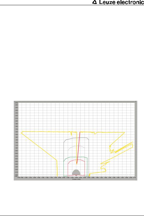
4.3Work space
The Work space screen area is used for graphically displaying measured and room contours and protective and warning field pairs. The software uses the following colors to differentiate the contours:
Table 4.1: Contour colors
Contour |
Color |
Minimum protective field |
Gray |
|
|
Protective field |
Red |
|
|
Warning field |
Green |
|
|
Deactivated protective |
Bright gray |
field |
|
|
|
Deactivated warning field |
Dark gray |
|
|
Measured contour |
Yellow/red |
|
|
Pic. 4.2: Contour display
You recognize the cursor position by a dark-blue circle that changes to a crosshairs when clicked.
With the appropriate authorization you can edit protective and warning fields on the work space (see chapter, "Edit protective and warning fields", page 33).
12 |
RS4soft |
Leuze electronic |

User interface
4.4Navigation area
In the navigation area the software shows the XY coordinates of the cursor position during the protective and warning field definition. When you click on the work space and pull out a zone with the mouse button pressed, the software shows the area in the position and end position lines. With these coordinates you can precisely locate objects on the work space and display them in detail.
With the arrow buttons arranged in a cross, you can move the displayed image section on the work space. Click on the middle button to optimally position the entire contour field.
Pic. 4.3: Navigation buttons
4.5Status line
In the Status line screen area you receive detailed information in five fields about:
•The communication between PC and Safety Sensor
•The Safety Sensor status
•The selected operating mode of the software
•The active protective/warning field status
•The logged on user's authorization level
Table 4.2: Communication
Display |
Status |
RS4 synchronous |
PC synchronizes the connection between the PC and the |
|
Safety Sensor |
|
|
RS4 connection |
Data transfer between PC and Safety Sensor is possible |
|
|
Table 4.3: Safety Sensor
Display |
Status |
RS4 -> Measurement mode |
Software records measurement data from the Safety |
|
Sensor |
|
|
RS4 -> Configuration |
Software transfers configuration data to the Safety Sensor |
|
(Sods switched off) |
|
|
RS4 -> Error |
Error in the Safety Sensor (Sods switched off) |
|
|
Leuze electronic |
RS4soft |
13 |

User interface
Table 4.4: Operating mode
Display |
Status |
PC -> Measured value |
Software in measured contour display operating mode |
display |
|
|
|
PC -> RS4 configuration |
Software in configuration operating mode |
|
|
PC -> Protective/warning |
Software in protective/warning field definition operating |
field definition |
mode |
|
|
PC -> RS4 system data |
Software in system data operating mode |
|
|
Table 4.5: Protective/warning field
Display |
Status |
PF/WF red |
Protective and warning field interrupted (Sods switched off) |
|
|
WF green |
Warning field interrupted |
|
|
Empty |
Protective and warning field free |
|
|
Table 4.6: Logged-on authorization level
Display |
Status |
Operator (Op) |
User is logged in with the Operator (Op) authorization level |
|
|
Maintainer (Ma) |
User is logged in with the Maintainer (Ma) authorization |
|
level |
|
|
Authorized Customer (AC) |
User is logged in with the Authorized Customer (AC) |
|
authorization level |
|
|
Production (Pr) |
User is logged in with the Production (Pr) authorization |
|
level. |
|
|
Development (De) |
User is logged in with the Development (De) authorization |
|
level. |
|
|
14 |
RS4soft |
Leuze electronic |

Operate
5 Operate
5.1Procedure when configuring
Proceed as follows to configure a Safety Sensor:
ªConnect PC with Safety Sensor
ªStart software and log in user
ªCreate Safety Sensor configuration with the wizard
ªCreate protective/warning field configuration
ªTransfer configuration to the Safety Sensor
ªCheck echo data
5.2Install software
Requirements:
•You do not need the Safety Sensor to install the software on the PC. If the devices are already connected with one another, ensure that the Safety Sensor is switched off.
•All Windows applications are closed.
ªInsert the CD ROM.
The installation starts automatically.
ªIf the installation does not start automatically, double-click on the setup.exe file.
ªIf you want to open the CD's menu, double-click on the setup.exe file.
ªSelect a language for the interface texts in the installation wizard and in the software and confirm with [OK].
The installation wizard starts.
ªClick on [Next].
The installation wizard opens the software license contract.
ªIf you agree with the software license contract, click on [Yes].
Leuze electronic |
RS4soft |
15 |

Operate
ªIf you agree with the recommended installation path, click on [Next]. or
If you want to enter another path, click on [Search]. Select another path, confirm with [OK] and click on [Next].
The wizard installs the software and creates a link on the desktop.
5.3Log in user
The following chapters provide basic information on the various access rights and the actual login process.
5.3.1Authorization concept
The access administration enables a target group-oriented login. The functions that are available depend on the selected authorization level. Functions that are not available in the software are identified by the bright gray buttons.
You do not require any individual user names for the login, but you must select an authorization level. The following authorization levels are available:
16 |
RS4soft |
Leuze electronic |

Operate
Table 5.1: Authorization levels and available functions
Authorization level |
Functions |
||
Operator (Op) |
• |
Adjust display |
|
• Display and analyze measured contour |
|||
|
|||
|
• Load configuration data from the Safety Sensor |
||
|
• Load status information from the Safety Sensor |
||
|
• |
Display diagnostics list |
|
|
• |
Create service file |
|
|
• |
Reset password |
|
|
|
||
Maintainer (Ma) |
In addition to the Operator (Op) functions: |
||
|
• Load configuration data from the Safety Sensor |
||
|
• Load configuration data from file |
||
|
• Load configuration data from file and transfer to the Safety |
||
|
|
Sensor |
|
|
• Transfer configuration data from the PC to the Safety |
||
|
|
Sensor |
|
|
• |
Print configuration data |
|
|
• |
Print protective/warning field |
|
|
|
||
Authorized Customer |
In addition to the Maintainer (Ma) functions, full access to all |
||
(AC) |
user-relevant functions and parameters: |
||
|
• Save configuration data as a file |
||
|
• Change all configuration parameters |
||
|
• Reset Safety Sensor to default values |
||
|
• Define and change protective/warning fields |
||
|
• Set reference contour in the protective field |
||
|
• Print and delete protective/warning fields |
||
|
• Load protective/warning field data from file |
||
|
• Save protective/warning field data |
||
|
• Transfer protective/warning field data from the PC to the |
||
|
|
Safety Sensor |
|
|
• Calibrate the front screen |
||
|
• |
Change passwords |
|
|
|
||
Production (Pr) |
Manufacturer-specific access |
||
|
|
||
Development (De) |
Manufacturer-specific access |
||
|
|
|
|
Leuze electronic |
RS4soft |
17 |

Operate
All authorization levels except Operator (Op) are protected with a password. There are the following password types:
•Default password: Valid for the software, cannot be changed
•Specific password: Valid for the Safety Sensor
The software saves the specific password in the connected Safety Sensor and therefore ensures that only authorized users can change the existing configuration.
The password that you must enter in the software depends on the login situation: Table 5.2: Login situations and password types
Login situation |
Password type |
Software is not connected with Safety Sensor |
Default password |
|
|
Software is connected with Safety Sensor |
Specific password |
|
|
Use the default password when you log in on the Safety Sensor for the first time. Change the default password immediately to a specific password. More information is provided in chapter "Login" on page 18 and chapter "Change password" on page 54.
5.3.2Login
Using software without Safety Sensor
You can use the software without the Safety Sensor, e.g. to edit existing configurations. The functionality of the software is limited.
Requirements:
•Software and Safety Sensor are not connected.
•The R232 serial interface must be active on the PC. If, for example, you use a laptop with a USB adapter, you must first install this interface where necessary.
ªClick on [Start] in the taskbar.
ªIn the start menu select Program > Leuze electronic > RS4soft > RS4soft.
The software starts.
The start screen with information on the version opens. The Change authorization level dialog box opens.
18 |
RS4soft |
Leuze electronic |

Operate
ªIn the Authorization level list select the Authorized Customer (AC) entry and enter the RS4LEUZE default password.
ªConfirm with [OK].
You can use the offered wizard (see page 24) and load a configuration from a file (see page 21).
Using software with the Safety Sensor
You can use the software with the Safety Sensor connected, e.g. to transfer an existing configuration to the Safety Sensor.
Requirements:
•The Safety Sensor is connected to the power supply.
•The Safety Sensor is connected to the PC and turned on.
If you switch on the Safety Sensor after the software start and have selected the
Maintainer (Ma) or Authorized Customer (AC) authorization level, you must first log in to the software with the default password.
ªClick on [Start] in the taskbar.
ªIn the Windows→ start menu select the menu items All programs > Leuze electronic > RS4soft > RS4soft.
The software starts.
The start screen with information on the version opens.
The Safety Sensor automatically contacts the connected PC.
The software automatically synchronizes the PC and the Safety Sensor.
The software automatically transfers the configuration from the Safety Sensor and checks the data.
The Change authorization level dialog box opens.
ªChange the entry in the Authorization level list. If you have selected the
Maintainer (Ma) or Authorized Customer (AC) entry, you must enter a password (see page 16).
When you log in for the first time, enter a suitable default password for your authorization level:
Maintainer (Ma): RS4IGOY
Authorized Customer (AC): RS4LEUZE
ªConfirm with [OK].
Leuze electronic |
RS4soft |
19 |

Operate
ªIf you have logged in with the Maintainer (Ma) or Authorized Customer (AC) authorization level for the first time, you must change your password (see page 64).
The software contacts and checks the connected Safety Sensor. The Scanner status information message appears.
ªThe status information includes administrative and safety-relevant parameters. Compare all safety-relevant parameters with the required parameters of the current application (see chapter, "Print status information", page 49).
ªClick on [Close].
You can execute the functions available on your authorization level. If you have logged in with the Authorized Customer (AC) or Maintainer (Ma) authorization level, you can use the offered wizard (see page 24) and load a configuration from
a file (see page 21).
5.4Create new Safety Sensor configuration
To create a new configuration, load an existing configuration and change its parameters. You will find basic information about configurations in chapter (see chapter, "Configuring the Safety Sensor", page 8).
A default configuration file is stored in the Examples folder of the program directory. This configuration file standard.rs corresponds with the Safety Sensor's standard configuration in its delivery status. You can use and change the default configuration file as a template.
See also:
•Load Safety Sensor configuration (see page 21)
•Change Safety Sensor configuration parameters (see page 23)
5.5Change existing Safety Sensor configuration
To change an existing configuration, load a configuration file and change the configuration.
See also:
•Load Safety Sensor configuration (see page 21)
•Change Safety Sensor configuration parameters (see page 23)
20 |
RS4soft |
Leuze electronic |
Operate
5.6Load Safety Sensor configuration
To create a new configuration or to change an existing configuration, you must first load an existing configuration. You can either open a locally saved configuration file or get the configuration from the Safety Sensor.
See also:
•Load from file (see page 21)
•Get from the Safety Sensor (see page 23)
5.6.1Load from file
You can load a configuration from the PC, e.g. from the hard disk or from an external drive.
If no Safety Sensor is connected, the load process starts after a passwordprotected login and use of the configuration wizard.
Requirement:
•You are logged in with the Maintainer (Ma) or Authorized Customer (AC) authorization level.
ªSelect Settings > Operating mode > Configuration. or
Click in the topic bar on [Configuration].
ªSelect File> Load configuration data from file.
or
Click on  .
.
Leuze electronic |
RS4soft |
21 |
Loading...