


 Loading...
ROTOSCAN RS4
Safety Laser Scanners
<![if ! IE]><![endif]>EN 2011/03 - 607144 We reserve the right to make technical changes
S A F E I M P L E M E N T A T I O N A N D O P E R A T I O N
O r i g i n a l o p e r a t i n g i n s t r u c t i o n s
© 2011
Leuze electronic GmbH + Co. KG In der Braike 1
D-73277 Owen - Teck / Germany Phone: +49 7021 573-0
Fax: +49 7021 573-199 http://www.leuze.com info@leuze.de
Version 8.6

|
|
|
Contents |
1 |
About this document ..................................................................................................................................................... |
|
6 |
1.1 |
Other applicable documents ......................................................................................................................................... |
|
6 |
1.2 |
Used symbols and signal words ................................................................................................................................... |
|
6 |
2 |
Safety............................................................................................................................................................................ |
|
7 |
2.1 |
Proper use .................................................................................................................................................................... |
|
7 |
2.2 |
Appropriately qualified person ...................................................................................................................................... |
|
7 |
2.3 |
Responsibility for safety ................................................................................................................................................ |
|
7 |
2.4 |
Laser ............................................................................................................................................................................. |
|
8 |
2.5 |
Handling the safety sensor ........................................................................................................................................... |
|
8 |
2.6 |
Usage limits .................................................................................................................................................................. |
|
8 |
2.7 |
Guarantee the availability of the safety sensor ............................................................................................................. |
|
9 |
2.8 |
Providing the company operating the machine with information................................................................................... |
9 |
|
2.9 |
Exemption of liability ................................................................................................................................................... |
|
10 |
3 |
Device description ...................................................................................................................................................... |
|
11 |
3.1 |
Device overview.......................................................................................................................................................... |
|
12 |
3.2 |
Display elements ........................................................................................................................................................ |
|
12 |
3.3 |
Mounting system (option) ........................................................................................................................................... |
|
14 |
3.4 |
ConfigPlug (option) ..................................................................................................................................................... |
|
14 |
4 |
Functions .................................................................................................................................................................... |
|
15 |
4.1 |
Start/restart interlock................................................................................................................................................... |
|
15 |
4.1.1 |
Start interlock .............................................................................................................................................................. |
|
15 |
4.1.2 |
Restart interlock .......................................................................................................................................................... |
|
15 |
4.2 |
Start test ..................................................................................................................................................................... |
|
15 |
4.3 |
Automatic start/restart................................................................................................................................................. |
|
15 |
4.3.1 |
Automatic start ............................................................................................................................................................ |
|
15 |
4.3.2 |
Automatic restart......................................................................................................................................................... |
|
16 |
4.4 |
Dust suppression ........................................................................................................................................................ |
|
16 |
4.5 |
Field pair switchover ................................................................................................................................................... |
|
16 |
4.6 |
Reference boundary monitoring ................................................................................................................................. |
|
17 |
4.7 |
MotionMonitoring ........................................................................................................................................................ |
|
17 |
5 |
Applications ................................................................................................................................................................ |
|
19 |
5.1 |
Stationary danger zone guarding................................................................................................................................ |
|
19 |
5.2 |
Stationary point of operation guarding ........................................................................................................................ |
|
20 |
5.3 |
Stationary access guarding ........................................................................................................................................ |
|
21 |
5.4 |
Mobile danger zone guarding ..................................................................................................................................... |
|
22 |
5.5 |
Mobile side guarding................................................................................................................................................... |
|
23 |
6 |
Mounting ..................................................................................................................................................................... |
|
24 |
6.1 |
Basic infos .................................................................................................................................................................. |
|
24 |
6.2 |
Basic infos on the protective field dimensioning ......................................................................................................... |
|
25 |
6.2.1 |
Handling unmonitored areas....................................................................................................................................... |
|
25 |
6.2.2 |
Protective field setup with adjacent safety sensors .................................................................................................... |
|
26 |
6.3 |
Stationary danger zone guarding................................................................................................................................ |
|
28 |
6.3.1 |
Beam level height ....................................................................................................................................................... |
|
29 |
6.3.2 |
Safety distance "S" ..................................................................................................................................................... |
|
29 |
6.3.3 |
Additional distance "C" because of the possibility of reaching over............................................................................ |
30 |
|
6.3.4 |
Machine response times, stopping time ..................................................................................................................... |
|
30 |
6.3.5 |
Application-conditional additional distances for safety distance "S" ........................................................................... |
31 |
|
6.3.6 |
Minimum distance "D" to the protective field contour.................................................................................................. |
|
31 |
6.4 |
Stationary point of operation guarding ........................................................................................................................ |
|
32 |
6.4.1 |
Safety distance "S" ..................................................................................................................................................... |
|
33 |
6.4.2 |
Additional distance C .................................................................................................................................................. |
|
33 |
6.4.3 |
Machine response times, stopping time ..................................................................................................................... |
|
33 |
6.4.4 |
Protective field and reference boundary ..................................................................................................................... |
|
34 |
6.5 |
Stationary access guarding ........................................................................................................................................ |
|
34 |
6.5.1 |
Safety distance "S" .................................................................................................................................................... |
|
35 |
6.5.2 |
Machine response times, stopping time ..................................................................................................................... |
|
35 |
Leuze electronic |
RS4 |
3 |
|

|
|
|
Contents |
6.5.3 |
Protective field contour and reference boundary |
........................................................................................................ |
36 |
6.6 |
Mobile danger zone guarding on DTSs ...................................................................................................................... |
|
36 |
6.6.1 |
Basic requirements ..................................................................................................................................................... |
|
37 |
6.6.2 |
Minimum distance D ................................................................................................................................................... |
|
37 |
6.6.3 |
Protective field dimensions ........................................................................................................................................ |
|
39 |
6.6.4 |
Test mode for MotionMonitoring ................................................................................................................................. |
|
39 |
6.7 |
Mobile side guarding on DTSs.................................................................................................................................... |
|
40 |
7 |
Technical data ............................................................................................................................................................ |
|
41 |
7.1 |
Safety.......................................................................................................................................................................... |
|
41 |
7.2 |
Optics.......................................................................................................................................................................... |
|
41 |
7.3 |
Protective field ............................................................................................................................................................ |
|
42 |
7.4 |
Warning field ............................................................................................................................................................... |
|
42 |
7.5 |
Measured data ............................................................................................................................................................ |
|
42 |
7.6 |
Electrical power supply .............................................................................................................................................. |
|
43 |
7.7 |
Software...................................................................................................................................................................... |
|
44 |
7.8 |
Ambient conditions ..................................................................................................................................................... |
|
44 |
7.9 |
Dimensions, weight..................................................................................................................................................... |
|
45 |
8 |
Electrical connection ................................................................................................................................................... |
|
47 |
8.1 |
Electrical power supply ............................................................................................................................................... |
|
47 |
8.2 |
Interfaces .................................................................................................................................................................... |
|
47 |
8.2.1 |
X1 plug interface assignment ..................................................................................................................................... |
|
48 |
8.2.2 |
Interface assignment, plug X2 .................................................................................................................................... |
|
49 |
8.3 |
Assemble cables......................................................................................................................................................... |
|
50 |
8.4 |
Integrating the safety sensor into machine control .........................................................................................system |
51 |
|
8.4.1 |
Downstream safety circuit with start/restart interlock, .................contactor monitoring, without field pair switchover |
51 |
|
8.4.2 |
Programmable logic controller (PLC) with corresponding ................................safety level and field pair switchover |
51 |
|
9 |
Parameters ................................................................................................................................................................. |
|
53 |
9.1 |
Administrative parameters .......................................................................................................................................... |
|
53 |
9.1.1 |
Safety Laser Scanner name ....................................................................................................................................... |
|
53 |
9.1.2 |
Description .................................................................................................................................................................. |
|
53 |
9.1.3 |
Start segment output .................................................................................................................................................. |
|
53 |
9.1.4 |
Stop segment output................................................................................................................................................... |
|
53 |
9.1.5 |
Output resolution ........................................................................................................................................................ |
|
53 |
9.1.6 |
Serial interface baud rate............................................................................................................................................ |
|
54 |
9.1.7 |
Alarm incident ............................................................................................................................................................. |
|
54 |
9.1.8 |
Precalculated measured values output....................................................................................................................... |
|
54 |
9.1.9 |
2nd measured value calculation segment .................................................................................................................. |
|
54 |
9.1.10 |
3rd measured value calculation segment ................................................................................................................... |
|
54 |
9.2 |
Safety-relevant parameters ........................................................................................................................................ |
|
55 |
9.2.1 |
Application .................................................................................................................................................................. |
|
55 |
9.2.2 |
Response times .......................................................................................................................................................... |
|
55 |
9.2.3 |
Dust suppression ........................................................................................................................................................ |
|
55 |
9.2.4 |
Applicable field pair selection with scanner start ........................................................................................................ |
|
56 |
9.2.5 |
Permitted field pair switchovers .................................................................................................................................. |
|
56 |
9.3 |
Field pair ..................................................................................................................................................................... |
|
56 |
9.3.1 |
Protective field/description .......................................................................................................................................... |
|
56 |
9.3.2 |
Warning field/description ............................................................................................................................................ |
|
56 |
9.4 |
MotionMonitoring ........................................................................................................................................................ |
|
56 |
9.4.1 |
Vehicle width............................................................................................................................................................... |
|
56 |
9.4.2 |
Protective field side additional distance ...................................................................................................................... |
|
56 |
9.4.3 |
Laser scanner installation point .................................................................................................................................. |
|
57 |
9.4.4 |
Warning field prerun time............................................................................................................................................ |
|
57 |
9.4.5 |
Vehicle response time ................................................................................................................................................ |
|
57 |
9.4.6 |
Brake wear and tear additional distance..................................................................................................................... |
|
57 |
9.4.7 |
Ambient influences additional distance....................................................................................................................... |
|
57 |
9.4.8 |
Speed with PF ............................................................................................................................................................ |
|
58 |
9.4.9 |
Braking distance with PF ............................................................................................................................................ |
|
58 |
9.4.10 |
Standstill monitoring ................................................................................................................................................... |
|
58 |
9.4.11 |
Creep and reverse ...................................................................................................................................................... |
|
58 |
Leuze electronic |
RS4 |
4 |
|

|
|
Contents |
10 |
Setting the device into service .................................................................................................................................... |
59 |
10.1 |
Before first start-up ..................................................................................................................................................... |
59 |
10.2 |
Switching on ............................................................................................................................................................... |
59 |
10.3 |
Shutting down ............................................................................................................................................................. |
59 |
10.4 |
Restart ........................................................................................................................................................................ |
59 |
10.5 |
Starting up the replacement device ............................................................................................................................ |
60 |
10.6 |
Starting up a safety sensor with the MotionMonitoring function................................................................................. |
61 |
11 |
Testing ........................................................................................................................................................................ |
66 |
11.1 |
Testing before first start-up and after machine modification ....................................................................................... |
66 |
11.2 |
Regular test by an appropriately qualified person ...................................................................................................... |
67 |
11.3 |
Daily functions test...................................................................................................................................................... |
67 |
12 |
Maintenance ............................................................................................................................................................... |
69 |
12.1 |
Clean the front screen ................................................................................................................................................ |
69 |
12.2 |
Clean scatter screens ................................................................................................................................................. |
70 |
13 |
Diagnostics and removing errors ................................................................................................................................ |
71 |
13.1 |
What to do in case of failure? ..................................................................................................................................... |
71 |
13.2 |
Operating displays of the LEDs .................................................................................................................................. |
71 |
13.3 |
LED warning and error displays.................................................................................................................................. |
72 |
13.4 |
Diagnostics codes....................................................................................................................................................... |
73 |
14 |
Repairs ....................................................................................................................................................................... |
78 |
14.1 |
Change the front screen ............................................................................................................................................. |
78 |
15 |
Disposing .................................................................................................................................................................... |
81 |
16 |
Service ........................................................................................................................................................................ |
82 |
17 |
Accessories ................................................................................................................................................................ |
83 |
17.1 |
Accessories to choose from........................................................................................................................................ |
83 |
Leuze electronic |
RS4 |
5 |
About this document
1 About this document
1.1Other applicable documents
The information on the safety sensor is distributed over several documents to make working with the documents easier. You will find the documents and programs for the safety sensor in the following table:
Purpose and target group of the document |
Document/software |
Source |
|
title |
|
|
|
|
Software for users of the machine* for safety sensor |
RS4soft |
Included with the product |
diagnostics if a fault occurs and for machine design |
|
delivery on CD-ROM** |
engineers* for configuring the safety sensor |
|
|
|
|
|
Notes for the machine design engineer* |
Safe implementation |
Art. no. 607144** |
|
and operation |
Included with the product |
|
(this document) |
delivery on CD-ROM |
|
|
|
Notes for the machine design engineer* for config- |
Safe parametering |
Art. no. 607143** |
uring the safety sensor (Software RS4soft instruc- |
|
Included with the product |
tions) |
|
delivery on CD-ROM |
|
|
|
Additional information on ROTOSCAN RS4/AS-i |
Additional information |
Art. no. 607060** |
|
for the ROTOSCAN |
Included with the product |
|
RS4-4 connecting and |
delivery on CD-ROM |
|
operating instructions |
|
|
|
|
Additional information on ROTOSCAN RS4/ |
Additional information |
Art. no. 605054** |
PROFIsafe |
for the ROTOSCAN |
Included with the product |
|
RS4-4 Laser Scanner |
delivery on CD-ROM |
|
connecting and operat- |
|
|
ing instructions |
|
|
|
|
*identifies the product that the safety sensor is installed in.
**You can download the current version of the software and all documents as PDF on the Internet at: http://www.leuze.com/rotoscan
1.2Used symbols and signal words
Table 1.1: |
Warning symbols and signal words |
|
|
|
Symbol for dangers |
|
|
NOTICE |
Signal word for property damage |
|
Indicates dangers that could damage the safety sensor if the measures for preventing |
|
danger are not implemented. |
|
|
CAUTION |
Signal word for minor injury |
|
Indicates dangers that could slightly injure you if the measures for preventing danger are |
|
not implemented. |
|
|
WARNING |
Signal word for serious injury |
|
Indicates dangers that could seriously or fatally injure you if the measures for preventing |
|
danger are not implemented. |
|
|
DANGER |
Signal word for life-threatening danger |
|
Indicates dangers that could seriously or fatally injure you if the measures for preventing |
|
danger are not implemented. |
|
|
Table 1.2: |
Other symbols |
Symbol for tips
Texts with this symbol provide you with further information on handling the safety sensor.
ªSymbols for action steps
Text passages with this symbol instruct you to perform actions.
Leuze electronic |
RS4 |
6 |

Safety
2 Safety
WARNING
If the safety sensor is not selected and used correctly, severe accidents may result.
ªCarefully follow all notices regarding the safety sensor.
ªMake certain that all other people also know and observe the notices that apply to them.
The documents are part of the product. Non-observance presents a high risk to personal health and life.
ªObserve the documents on the CD ROM included with the product. Alternatively you can also download the current documents on the Internet. Internet: http://www.leuze.com/rotoscan
For an overview of other applicable documents (see chapter 1.1 „Other applicable documents“).
ªRead and observe the documents that apply for your activities in full before you work with the safety sensor.
Print out the relevant text parts to make reading and handling the documents easier.
2.1Proper use
The safety sensor is used to protect people in danger zones or at points of operation on machines and to protect objects and machine parts against the dangers of collision.
The safety sensor may only be used after it has been put into operation in accordance with the applicable instructions, relevant rules and regulations on occupational health and safety at work and the recognized safety-related rules and regulations have been placed on the machine by an appropriately qualified person.
The safety sensor must be integrated into the machine's electrical control system in such a way that an activation of the safety function safely stops or interrupts the dangerous process before a person can be endangered.
If the machine does not allow the dangerous movement to be stopped at all times, you may not install the safety sensor. Do not use the safety sensor, for example, together with a press with form-locking coupling.
2.2Appropriately qualified person
Appropriately qualified is a person that,
•has acquired adequate knowledge and skills with regard to operating the machine, the configuration and diagnostics software and testing the safety sensor through training and practical experience and has proven their capabilities in practice,
•and is so well versed in the applicable rules and regulations on occupational health and safety at work and the recognized safety-related rules and regulations that he/she can evaluate the safety of the machine,
•and has been instructed in the machine's operation and safety rules and regulations,
•and has read and understood the respective applicable instructions for the safety sensor and the machine's operating instructions,
•and has been charged by the respective person responsible for the machine's safety with the testing of the safety sensor.
2.3Responsibility for safety
The responsibility for the safety-assured use of the safety sensor and compliance with the regulations and directives that apply in the country of use lies with the machine's manufacturer and company operating the machine.
Leuze electronic |
RS4 |
7 |
Safety
The manufacturer of the machine is responsible for:
•The safe design and construction of the machine.
•The safe implementation of the safety sensor.
•The provision of all relevant information to the operator company.
•Compliance with all regulations and directives for safely putting the machine into operation.
The operating company is responsible for:
•Instructing the operating staff.
•Maintaining the safe operation of the machine.
•Compliance with all occupational health and safety at work regulations and directives.
Passwords
Improperly set parameters on the safety sensor can cause serious accidents. The configuration of the safety sensor is therefore protected by passwords.
ªEnsure that the passwords are kept locked away by the security officer.
ªThe people responsible for the machine's safety must ensure that the appropriately qualified person can properly perform the tests and work on the machine and the safety sensor in accordance with their intended use.
2.4Laser
The safety sensor corresponds with laser class 1. Additional activities for shielding the laser beams are not required (safe for eyes).
Laser Klasse 1
Laser Class 1
Laser de Classe 1
ªObserve the applicable legal and local regulations for operating laser equipment.
2.5Handling the safety sensor
ªObserve the permissible environmental conditions for storage and operation.
Front screen and scatter screens
The safety sensor's front screen and scatter screens must be clean, free of damage and properly installed.
ªAvoid touching the front screen and scatter screens.
ªClean dirty screens immediately (according to these instructions).
ªHave damaged screens replaced immediately (according to these instructions).
Screwed-on cables
Improper handling can damage the safety sensor and result in safety-relevant signals not being sent. The safety sensor's IP type of protection is only guaranteed with screwed-on plug cover caps.
ªOnly operate, transport and store the safety sensor with screwed-on control cable (X1) and PC cable (X2) or dummy plug (X2).
2.6Usage limits
Only on closed rooms
The safety sensor is not suitable for use outdoors or under conditions with significant temperature fluctuations. Humidity, condensation and other weather influences can impair the safety function.
ªOnly use the safety sensor in closed rooms.
ªObserve all technical data and ambient conditions.
Industrial use only
The safety sensor is not suitable for residential areas, because it can cause radio interferences.
ª Only use the safety sensor in industrial environments.
Leuze electronic |
RS4 |
8 |

Safety
Not on vehicles with combustion engines
The safety sensor is not suitable for use on vehicles with combustion engines, because alternators or ignition systems can cause EMC disturbances.
ª Only use the safety sensor on vehicles without a combustion engine.
No changes on the safety sensor
The construction of the safety sensor may not be changed, because the protective function can no longer be guaranteed if the safety sensor is changed. Manipulating the safety sensor also voids all warranty claims against the manufacturer of the safety sensor.
Service life TM according to ISO 13849-1: 2006
Values PL and PFHd of the safety sensor refer to a service life TM of 20 years.
Repairs or the exchange of parts subject to wear and tear do not extend the service life.
Protective function limits
The safety sensor does not protect against:
•Projected (thrown out) parts
•Splashing/spraying liquids
•Gases and vapors
•Radiation
2.7Guarantee the availability of the safety sensor
Vapors, smoke, dust, particles
Vapors, smoke, dust and all particles visible in the air can cause the machine to switch off unintentionally. This can mislead the user into bypassing the safety devices.
ªDo not use the safety sensor in environments in which heavy vapors, smoke, dust or other visible particles occur at the beam level.
No stray light
Light sources can impair availability. Interfering light sources are:
•Infrared light
•Fluorescent light
•Strobe light
ªEnsure that there are no interfering light sources at beam level.
ªPrevent reflective surfaces at beam level.
ªWhere applicable, take additional protective field distances into account.
ªImplement all additional measures to ensure that any special use of any effected beam types does not impair the safety sensor's operation.
No obstructions in the protective field
ª Do not bring any additional window materials into the area monitored by the safety sensor.
2.8Providing the company operating the machine with information
The machine manufacturer must inform the company operating the machine in detail and comprehensibly about all activities that are required for the safety-assured operation of the machine with the safety sensor. This also includes the forwarding of information from these instructions that the operating company requires.
The type and content of the information may not, however, result in any questionable safety-related actions by the user.
Where required, safety key, special tools and passwords should be maintained under the control of one or more responsible or authorized people.
Leuze electronic |
RS4 |
9 |

Safety
2.9Exemption of liability
Leuze electronic GmbH + Co. KG is not liable in the following cases:
•safety sensor is not used as intended
•safety notices are not adhered to
•reasonably foreseeable misuse is not taken into account
•mounting and electrical connection are not properly performed
•proper function is not tested, see chapter 11 „Testing“
•changes (e.g., constructional, electrical) are made to the safety sensor.
Leuze electronic |
RS4 |
10 |
Device description
3 Device description
The ROTOSCAN RS4 safety sensor is an optical, two-dimensional measuring Safety Laser Scanner. The safety sensor transmits periodic light pulses via a rotating deflection unit. The light pulses are reflected by obstructions, e.g. people, and received by the safety sensor again and analyzed. The safety sensor calculates the precise position of the obstruction from the light travel time and the angle of the deflection unit at that time. If the obstruction is within a predefined area, the protective field, the safety sensor performs a safety-related switching function. It switches the safety-related switching outputs off.
Only when the protective field is free again does the safety sensor reset the safety-related switching function, either automatically or following confirmation, depending on the operating mode.
The safety sensor can even detect people when they are wearing very dark clothes, which have a very weak diffuse reflectance.
1
|
|
|
|
|
|
|
|
|
|
|
|
|
|
d |
|
|
|
|
|
|
|
e |
|
|
|
|
|
|
|
|
|
||||
|
|
|
|
SF |
|
||||||
|
|
|
|
|
|
|
|
|
|||
|
|
|
|
|
|
WF |
|
|
|
||
|
|
|
|
|
|
a |
|
|
|
||
|
1 |
2 |
3 |
4 |
|
|
|
|
|
||
Figure 3.1: Safety sensor detection ranges |
|
|
|
|
|
|
|
||||
|
|
|
|
|
|
|
|
||||
Pos. |
Description |
|
|
|
|
|
Comment |
||||
|
|
|
|
|
|
|
|
||||
1 |
Configured warning field |
|
|
|
|
|
Example |
||||
|
|
|
|
|
|
|
|
||||
2 |
Configured protective field |
|
|
|
|
|
Example |
||||
|
|
|
|||||||||
3 |
Object (person) in the protective field |
Example |
|||||||||
|
|
|
|
|
|
|
|
|
|
||
4 |
Safety sensor |
|
|
|
|
|
|
|
|
||
|
|
|
|||||||||
a |
Maximum measurement value logging |
50 m |
|||||||||
|
|
|
|
|
|||||||
d |
Configurable protective and warning field extension |
-5° |
|
|
|||||||
|
|
|
|
|
|||||||
e |
Configurable protective and warning field extension |
+5° |
|
|
|||||||
|
|
|
|
|
|
|
|
|
|
||
PF |
Maximum protective field |
|
|
|
|
|
|
|
|
||
|
|
|
|
|
|
|
|
|
|
||
WF |
Maximum warning field |
|
|
|
|
|
|
|
|
||
|
|
|
|
|
|
|
|
|
|
|
|
Leuze electronic |
RS4 |
11 |
Device description
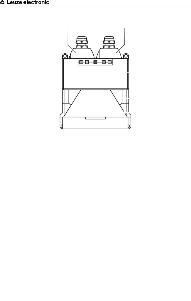
3.1Device overview
11 |
22 |
 33
33
 44
44
 55
55
1X1 interface for controlling the machine, with protective cap
2X2 interfaces for PC/laptop, with protective cap
3Status display
4Scatter screens
5Front screen
Figure 3.2: Safety sensor overview
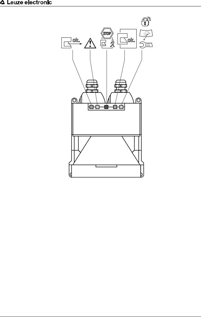
3.2Display elements
Status display
Five LEDs on the front show the safety sensor's status
Leuze electronic |
RS4 |
12 |
Device description
1 2 3 4 5
Figure 3.3: Status displays
Leuze electronic |
RS4 |
13 |
|
|
|
Device description |
Table 3.1: |
Meaning of the LEDs |
|
|
LED |
|
|
Meaning |
ok. |
1, green |
Lights |
Sensor function is active; the active protective field is free. |
|
|
Flashes with 2 Hz |
Fault on the field pair control inputs. |
|
|
Flashes with 4 Hz |
MotionMonitoring has detected a fault. |
|
2, yellow |
Lights |
Active warning field is seized. |
|
|
Flashes with 2 Hz |
Front screen is dirty. |
|
|
Flashes with 4 Hz |
ConfigPlug configuration is not compatible with the safety |
|
|
|
sensor. |
STOP |
3, red |
Lights |
Safety-related switching outputs (OSSD 1 and 2) are |
|
|
switched off. |
|
|
|
|
|
|
4, green |
Lights |
Safety-related switching outputs (OSSD 1 and 2) are |
ok. |
|
|
switched on. |
|
5, yellow |
Lights |
Start/restart interlock locked. |
|
|
Flashes with 2 Hz |
Front screen is dirty. |
|
|
Flashes with 4 Hz |
Fault |
3.3Mounting system (option)
The mounting system makes it easier to install and align the safety sensor. The mounting system is available as an accessory (see chapter 17.1 „Accessories to choose from“).
3.4ConfigPlug (option)
The ConfigPlug makes it easier to swap out the safety sensor. It saves the configuration when the PC is configured and automatically transfers it with the device swap-out to the replacement device. The ConfigPlug is available as an accessory (see chapter 17.1 „Accessories to choose from“).
Leuze electronic |
RS4 |
14 |

Functions
4 Functions
The functions of the safety sensor must be matched to the respective application and its safety requirements. You can activate, deactivate and adjust functions with parameters (list of all parameters of the safety sensor see chapter 9 „Parameters“). You configure the functions with the help of the RS4soft configuration and diagnostics software.
4.1Start/restart interlock
The start/restart interlock has two functions:
•Start interlock
•Restart interlock
Using start/restart interlock
ªIn addition to the safety sensor you must also install the start/restart button. The machine operator starts the machine with this start/restart button.
ªPosition the start/restart button outside the danger zone so that it cannot be activated from the protective fields and danger zones. The operator must be able to see all danger zones from this position.
ªIdentify the zone to be released on the start/restart button so that its meaning is clear and easy to understand.
ªEnsure that nobody is in the danger zone before pressing the start/restart button.
4.1.1Start interlock
The start interlock function prevents the machine from starting automatically after switching on or after the power supply returns.
The machine only starts when you press the start/restart button.
4.1.2Restart interlock
The restart interlock prevents the machine from starting automatically, as soon as the protective field is free again. The restart interlock function always includes the start interlock function.
The machine only starts again when you press the start/restart button.
4.2Start test
The start test function compels the operator to interrupt the protective field once after the safety sensor start, e.g. with a test rod. Only then can the machine be started.
Using the start test
If you combine the start test with the automatic restart function, the start test serves as an automatic start/ restart signal.
4.3Automatic start/restart
The machine starts automatically as soon as the machine is switched on or the supply voltage returns and when the protective field is free again.
Using automatic start/restart
You can use the automatic start/restart function under the following conditions.
•The automatic start/restart function is taken over by a downstream safety-related component of the machine control system.
or
•It is not possible to walk behind or go around the effective protective field.
ªAllow for an optical and/or acoustic start warning.
4.3.1Automatic start
The automatic start function starts the machine automatically as soon as the supply voltage is present.
Leuze electronic |
RS4 |
15 |

Functions
4.3.2Automatic restart
The automatic restart function starts the machine automatically as soon as the protective field is free again.
4.4Dust suppression
The dust suppression function increases the availability of the safety sensor when small particles are in the air, e.g. material chips or insects.
Only deactivate the dust suppression function when, in addition to people, the safety sensor must also detect extremely fast and small objects in your application.
If you use the safety sensor for the mobile danger zone guarding of DTSs, you must select the speed range of your vehicle to optimize dust suppression.
4.5Field pair switchover
The safety sensor has four or eight field pairs. Switchover between the field pairs is possible at all times, provided the operating situation allows this.
During the switchover process the safety sensor monitors the field pair activated before the changeover until a new one has been clearly activated. Use the field pair switchover when the danger zones vary depending on the activity of the machine or the operating status, e.g. driverless transportation system (DTSs), to control the protective field switchover for straight and curved stretches.
If the rules for field pair switchover are not complied with, the safety sensor signals a fault and the machine stops.
Using field pair switchover
You can configure and switch over the field pairs according to the different requirements. The switchover is performed via the corresponding control inputs on the X1 interface.
The precepts for the switchover depend on the amount of the selected field pairs and their numbers. The activated field pair must correspond with the respective operating mode. The time of the switchover must correspond with the machine's risk assessment. You must take the braking distances, response times and machine stopping times, e.g. influenced by overlapping protective fields, into account.
If these rules are not complied with, the safety sensor goes to a fault status within 40 ms. The green LED 1 flashes with 2 Hz.
The following rules apply for switching over four field pairs:
•First the control unit must switch to a new field pair before it switches of the previous one.
•The switchover must be made within 1 sec. Both field pairs are monitored during the switchover time.
•All field pairs must never be deactivated during the switchover.
•The switchover process performed by the control system must agree with the safety sensor's configuration. This configuration is specified with the configuration and diagnostics software.
Table 4.1: |
Connection of control inputs FP1 to FP4 with activation of field pairs 1 to 4. |
|||||
|
|
|
|
|
|
|
Field pair |
|
Control input |
|
|
Description |
|
|
|
|
|
|
|
|
|
|
FP1 |
FP2 |
FP3 |
FP4 |
|
|
|
|
|
|
|
|
1 |
|
1 |
0 |
0 |
0 |
Field pair 1 is active |
|
|
|
|
|
|
|
2 |
|
0 |
1 |
0 |
0 |
Field pair 2 is active |
|
|
|
|
|
|
|
3 |
|
0 |
0 |
1 |
0 |
Field pair 3 is active |
|
|
|
|
|
|
|
4 |
|
0 |
0 |
0 |
1 |
Field pair 4 is active |
|
|
|
|
|
|
|
The following rules apply for switching over eight field pairs:
•The switchover must be made within 40 ms, i.e. after 40 ms an input connection must be valid and stable. The old field pair is monitored during the switchover time. The new field pair is monitored after max. 80 ms.
•The switchover process performed by the control system must agree with the safety sensor's configuration. This configuration is specified with the configuration and diagnostics software.
Leuze electronic |
RS4 |
16 |
Functions
Table 4.2: Connection of control inputs FP1 to FP4 with activation of field pairs 1 to 8.
Field pair |
Control input |
|
|
Description |
|
|
|
|
|
|
|
|
FP1 |
FP2 |
FP3 |
FP4 |
|
|
|
|
|
|
|
1 |
1 |
0 |
0 |
0 |
Field pair 1 is active |
|
|
|
|
|
|
2 |
0 |
1 |
0 |
0 |
Field pair 2 is active |
|
|
|
|
|
|
3 |
0 |
0 |
1 |
0 |
Field pair 3 is active |
|
|
|
|
|
|
4 |
0 |
0 |
0 |
1 |
Field pair 4 is active |
|
|
|
|
|
|
5 |
1 |
1 |
1 |
0 |
Field pair 5 is active |
|
|
|
|
|
|
6 |
1 |
1 |
0 |
1 |
Field pair 6 is active |
|
|
|
|
|
|
7 |
1 |
0 |
1 |
1 |
Field pair 7 is active |
|
|
|
|
|
|
8 |
0 |
1 |
1 |
1 |
Field pair 8 is active |
|
|
|
|
|
|
WARNING
Field pair switchover to field pair 8 deactivates the monitoring function
No field pair is now monitored; the safety outputs (OSSDs) remain constantly active.
ªNever start the safety sensor with field pair 8.
ªOnly use field pair 8 when there is no danger for people present, e.g. with vehicles in creep and reverse, in the area of loading or park positions or during machine cycles with which there is no danger for the operating staff.
4.6Reference boundary monitoring
The reference boundary monitoring function prevents unintentional misalignment and deliberate manipulation of the safety sensor. If a protective field contains an area with reference boundary, the safety sensor not only monitors interruptions of the protective field, it also monitors the concurrence of the measured area contour with the set reference boundary. If the measurement values of the area contour deviate from the defined reference boundary by more than the tolerance zone, i.e., if no object is detected in the area with reference boundary, the safety sensor switches off and the safety-related switching outputs (OSSDs) switch to off. The reference boundary function is set together with the definition of the protective field boundaries.
4.7MotionMonitoring
The MotionMonitoring function assists you during the configuration of the safety sensor for the mobile danger zone guarding application for side-tracking skates and, during travel operation of the side-tracking skate, monitors whether the control has selected the correct protective field for the given operating situation.
Using its internal measurement values, the safety sensor calculates the current speed of the side-tracking skate and compares this value with the speed configured in the speed matrix of the safety sensor for the protective field. This control function of MotionMonitoring leads to the following behavior:
•If the speed is higher than the speed given for the protective field, the safety sensor corrects by one protective field upwards. If a second correction is required with an even faster speed, the safety sensor stops the side-tracking skate.
•If the maximum speed is exceeded, the safety sensor stops the side-tracking skate immediately.
Two further functions are integrated into the MotionMonitoring function, which are assigned to the two field pairs, 7 and 8:
•Further travel blocking – field pair 7
•Creep and reverse – field pair 8
Leuze electronic |
RS4 |
17 |

Functions
Further travel blocking
The further travel blocking function prevents the side-tracking skated from moving as long as field pair 7 is active. The safety sensor switches the safety-related switching outputs in field pair 7 off. The sidetracking skate can start to move again when the control switches to another protective field.
Creep and reverse
A safety sensor is mounted in both directions when a side-tracking skate travels forwards and backwards. The creep and reverse function deactivates the safety sensor that is positioned opposing the current travel direction. This safety sensor only monitors the speed and direction of movement: no protective field and no warning field is monitored; the safety-related switching outputs remain set to ON. The maximum speed with a creep speed is 100 mm/s. If the side-tracking skate moves faster than 100 mm/s, the safety sensor switches the safety-related switching outputs off and stops the side-tracking skate. The creep function is used as the side-tracking skate approaches the minimum distance to loading and unloading stations.
Using MotionMonitoring
Requirements for using the MotionMonitoring function:
•Side-tracking skate (AGV) with linear movement
•Transportation path length max. 50 m
•Transportation path restricted at both ends by a wall or boundary
Pedestrian traffic on the transportation path is possible because it is included in the calculations by the safety sensor
•Side-tracking skate speed 6 m/s
•Only one side-tracking skate per path
ªEnter the speed levels of the AGV and the braking distance with maximum speed in the speed matrix with the configuration.
The software interpolates the missing braking distances and automatically defines the protective and warning fields.
During the initial start up, the configuration and diagnostic software displays the calculated measurement values for speed and distance and a speed monitoring status display in a separate dialog field.
Notices on starting up a safety sensor with the MotionMonitoring function (see chapter 10 „Setting the device into service“).
Function sequence
The protective field activated by the vehicle control— specified by protective field contour and travel speed— is monitored by the safety sensor for protective field violation and excess travel speed!
The following steps describe the principle operating procedure of the MotionMonitoring function:
•Via 4 standard outputs, the vehicle control activates the protective field that is adapted to the operating system on the control inputs of the safety sensor:
•small protective field for slow travel
•medium protective field for moderate travel
•large protective field for fast travel
•PF8 for reverse travel
•The safety sensor monitors this protective field and switches off in the event of a violation.
•While the protective field is free, the safety sensor ascertains the current travel speed and travel direction.
•The travel speed and travel direction are compared with the values configured in the speed matrix.
•If in agreement, i.e., the measured speed is smaller than the configured value, the system functions correctly and the safety sensor activates alarm output 2.
•If the measured speed is greater than the configured value, the safety sensor assumes that a fault has occurred in the system and deactivates alarm output 2.
Faults lead to two escalation levels:
•The protective field is corrected for a short time (5 s) while the next larger is automatically monitored by the safety sensor.
•If the speed increases further or if the maximum speed is exceeded, the safety sensor switches off the safety-related switching outputs; an entry appears in the diagnostics list.
Leuze electronic |
RS4 |
18 |
Applications
5 Applications
The following chapters essentially describe the safety sensor's usage possibilities. To safely configure and mount the safety sensor for the respective application (see chapter 6 „Mounting“).
5.1Stationary danger zone guarding
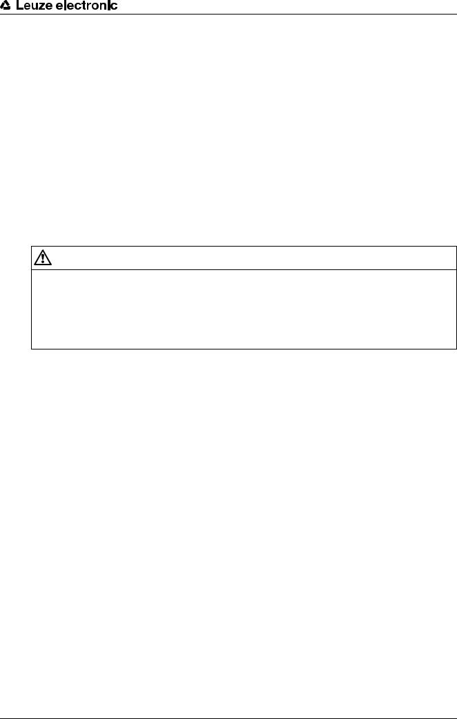
Stationary danger zone guarding enables a very spacious protection of people on machines that are to remain as accessible as much as possible. The safety sensor is applied as a stop-activating and presencedetecting protective device. The safety sensor's protective field is set up horizontally in front of the machine or system's point of operation.
You can also use the stationary danger zone guarding if you do have to guard areas under the machine or at the rear that are not visible.
1 |
2 |
1 |
36 |
4 |
35 |
3 |
1EMERGENCY STOP command device and start/restart button
2Safety sensor
3Protective field 2, activated
4Protective field 1, deactivated
5Warning field 2, activated
6Warning field 1, deactivated
Figure 5.1: Stationary danger zone guarding with two alternating work areas
Leuze electronic |
RS4 |
19 |
Applications
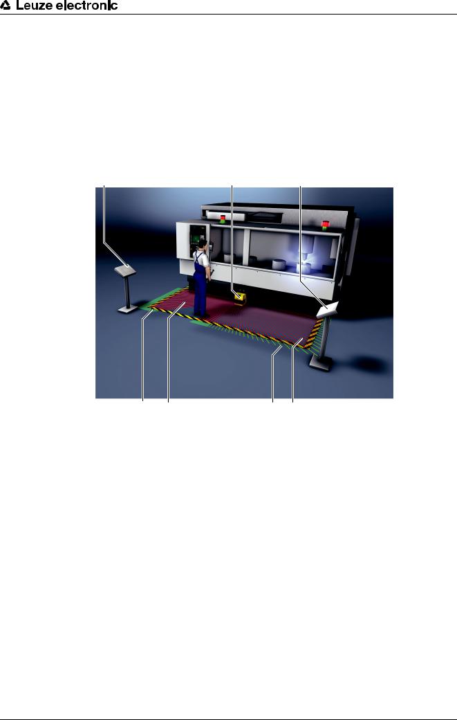
5.2Stationary point of operation guarding
Hand and arm protection are always required when people must work at the point of operation. The safety sensor is applied as a stop-activating and presence-detecting protective device. The safety sensor's protective field is set up vertically in front of the machine or system's point of operation. With small protective field dimensions the safety sensor provides the correspondingly required high resolution level. A sufficient safety distance to the point of operation ensures the finger protection.
5 1
3 |
4 |
32 |
3 |
1Safety sensor
2Reference boundaries of both protective fields
3EMERGENCY STOP command device and start/restart button
4Protective field 1, activated
5Protective field 2, deactivated
Figure 5.2: Stationary point of operation guarding with protective field switchover
Leuze electronic |
RS4 |
20 |
Applications
5.3Stationary access guarding
Stationary access guarding protects people that step into a danger zone. The vertically aligned protective field of the safety sensor detects the passage of a person. A side post and the floor serve as reference boundary for monitoring the position of the protective field. In contrast to danger zone guarding, the safety sensor no longer registers a person in the danger zone after the passage. This is why the start/restart interlock function is vital for access guarding.
1
3 |
4 |
32 |
1Safety sensor
2Reference boundary of the protective field
3EMERGENCY STOP command device and start/restart button
4Protective field
Figure 5.3: Stationary access guarding
Leuze electronic |
RS4 |
21 |
Applications
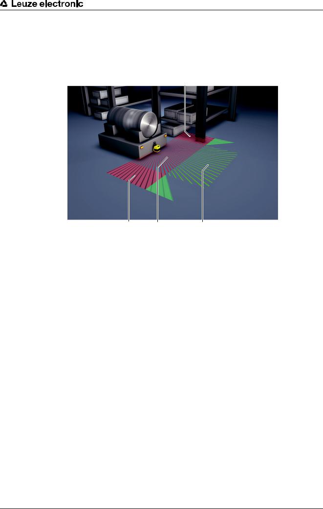
5.4Mobile danger zone guarding
Mobile danger zone guarding protects people that are located in the transportation path of an automated guided vehicle. The distance between the protective field front edge and the vehicle front must be greater than the stopping distance of the vehicle with selected speed and maximum load. A safe control system selects speed-dependent protective fields and can activate side horizontal protective fields for curved stretches.
3
34 |
41 |
32 |
1Protective field 1 for forward travel, activated
2Warning field 1 for forward travel, activated
3Protective field 2 for curved stretch, left, deactivated
4Protective field 3 for curved stretch, right, deactivated
Figure 5.4: Mobile danger zone guarding
Leuze electronic |
RS4 |
22 |

Applications
5.5Mobile side guarding
Mobile side guarding protects people and objects that are located on the vehicles path. This application is used when very low arranged conveyor lanes do not permit an unobstructed passage of horizontal, lateral overlaying protective fields. The safety sensors are positioned laterally and the protective fields are arranged vertically, at a slight tilt. The position of the front edges of the side protective fields is oriented here on the position of the front edge of the horizontal protective field.
4
32 |
43 |
31 |
1Protective field and warning field pair for forward travel, activated
2Protective field and warning field pair for reverse travel, deactivated
3Protective field and warning field pair for side guarding, right, activated
4Protective field and warning field pair for side guarding, left, activated
Figure 5.5: Mobile side guarding on side-tracking skates
Leuze electronic |
RS4 |
23 |

Mounting
6 Mounting
6.1Basic infos
The safety sensor's protective function is only guaranteed when the device arrangement, configuration, protective field dimensioning and installation are coordinated with the respective application.
The installation work must only be performed by an appropriately qualified person in compliance with the applicable standards and these instructions. The installation must be thoroughly inspected on completion.
ª You must observe and comply with the respective relevant machine-specific standards and regulations.
Basic procedure
ª Select the appropriate device type for the application.
Application |
Device type |
Resolution |
Configuration and installa- |
|
|
|
tion notes |
|
|
|
|
Stationary danger zone safeguarding |
RS4-x |
50-70 mm |
see chapter 6.3 „Stationary |
|
RS4-xE |
|
danger zone guarding“ |
|
|
|
|
Stationary point of operation guarding |
RS4-xE |
30-40 mm |
see chapter 6.4 „Stationary |
|
|
|
point of operation guarding“ |
|
|
|
|
Stationary access guarding |
RS4-xE |
150 mm |
see chapter 6.5 „Stationary |
|
|
|
access guarding“ |
|
|
|
|
Mobile danger zone guarding on DTSs |
RS4-x |
70 mm |
see chapter 6.6 „Mobile dan- |
|
RS4-xM |
|
ger zone guarding on DTSs“ |
|
|
|
|
Mobile side guarding on DTSs |
RS4-x |
150 mm |
see chapter 6.7 „Mobile side |
|
|
|
guarding on DTSs“ |
|
|
|
|
ªDetermine the installation point.
ªDetermine whether you are going to install the safety sensor with or without the mounting system.
ªDuring mounting, use the four supplied M5 screws or four similar screws with a diameter of 5 mm, and make certain that the mounting elements or mounting construction supports at least four times the weight of the device with or without mounting system.
ªDetermine the size of the protective field on the basis of the point of installation, the calculated safety distances and additional distances.
ªDetermine the start/restart operating mode required for the application.
ªIf you are using start/restart interlock, determine the position for the start/restart button.
ªDetermine the conditions for the field pair switchover, if required.
ªConfigure the safety sensor with the configuration and diagnostics software.
Many safety-relevant parameters are preset in the configuration and diagnostics software. Use these preset values where possible.
ªCreate a record document for the device configuration and protective field dimensioning. The document must be signed by the person responsible for the configuration.
Include this document with the machine documentation.
ªInstall protective enclosures or safety bars if the safety sensor is in an exposed position.
ªIf there is a risk that the safety sensor will be used as a climbing aid, install a suitable physical cover over the safety sensor.
Ensure that machine parts, protective grids or covers do not impair the safety sensor's field of vision.
Leuze electronic |
RS4 |
24 |
Mounting
6.2Basic infos on the protective field dimensioning
ªDimension the protective field big enough that the safety sensor's switch-off signal can stop the dangerous movement in good time.
If several protective fields are selected with field switchover, this condition applies for all protective fields.
Protective fields with a radius of less than 200 mm (safety sensor close range) are not permitted and are therefore preset as minimum contour.
ªIf you cannot sufficiently dimension a protective field, use additional protective measures, e.g. protective grids.
ªEnsure that the protective field cannot be walked behind in the direction of the danger zone.
ªObserve all delay times, e.g. safety sensor response times, control element response times, braking times or machine or AGV stopping times.
ªTake changed delay times, which, for example, can be caused by reducing the braking force, into account.
ªObserve shadowing effects, e.g. surfaces and areas behind static objects. People in the shadows of these objects will not be detected by the safety sensor.
ªObserve the lateral tolerance when dimensioning the protective fields (see chapter 7 „Technical data“).
ªDo not use cone-shaped protective field contours, as these do not guarantee any protective effect.
ªTake the additional distances required for the application into account.
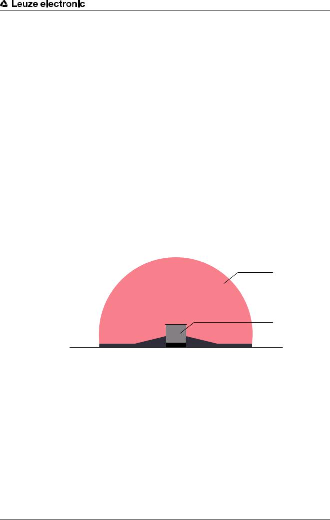
6.2.1Handling unmonitored areas
There is an area behind the safety sensor that the safety sensor does not monitor. Unmonitored areas can also materialize, e.g. if you install a safety sensor on a rounded off vehicle front.
It must not be possible to walk behind unmonitored areas.
2
1
 3
3
1Safety sensor
2Protective field
3Unmonitored area
Figure 6.1: Protective field shape – unmonitored areas
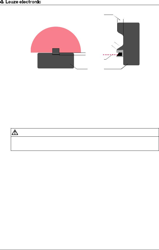
ªPrevent access to an unmonitored area with screens.
ªPrevent walking behind by countersinking the safety sensor into the machine contour.
Leuze electronic |
RS4 |
25 |
Mounting
1
 2
2
5
3 3
 1
1
2
4 |
4 |
1Countersinking into the machine contour
2Protective field
3Safety sensor
4Machine
5Physical cover
Figure 6.2: Stepping behind protection by countersinking into the machine contour
ªUse a physical cover set at an angle over the safety sensor if you expect that the safety sensor will be used as a climbing aid or standing surface.
6.2.2Protective field setup with adjacent safety sensors
The safety sensor has been developed in a way that prevents several safety sensors from interfering with one another as much as possible. Several adjacent safety sensors can, however, cause the response time to increase if the fields overlap.
WARNING
The response time extends with reciprocal influencing of adjacent safety sensors.
ªIf you do not plan for any measures against reciprocal influencing, take a response time extension of 40 ms into account with the safety distance calculation.
ªPlan for shielding with stationary applications.
The shielding must be at least as high as the safety sensor's front screen and flush with the front housing edge.
If you plan for a shielding that is still within the countersinking in the machine contour, the resolution of the protective fields must not be impaired at any accessible points.
You require the reciprocal shielding with both horizontal and vertical alignment of the protective fields.
Leuze electronic |
RS4 |
26 |
Loading...