

Page 1

BA 11.1031
Show/Hide Bookmarks
453 985 EN
Operating Instructions
Simplabelt
Compact Units
Page 2

What is new / what has changed ?
Show/Hide Bookmarks
Material No. Edit ion Important Content s
00 178 416 1.0 06/94 TD09 1st edition First edition for pilot series
00 390 299 1.0 01/96 TD09 1st edition
Replaces 178 415
00 390 299 2.0 07/97 TD09 2nd edition
Replaces 1st edition
00 453 985 1.0 05/02 TD09 1st edition
Replaces 390 299
E 1998 - 2001 Lenze Drive Systems GmbH
No part of this documentation may be re produced or made accessible to third parties without written consent by Lenze Drive Systems GmbH.
All indications given in these Operating instructions have been selected carefully. We will include necessary corrections in subsequent editions.
Completely revised
Product key completed
Chapter 3.3.2 Ambient media: new
Chapter 6.4 Spare parts new
Chapter 3.1.2: Item numbers of spare parts list adapted
Chapter 6.1: Maintenance intervals completed
Chapter 6.4: Order form completed
BA 11.1031
Author: Lenze Drive Systems GmbH
Edition: 1.0 05/02
2
BA S’belt KEEN 1.0
l
Page 3
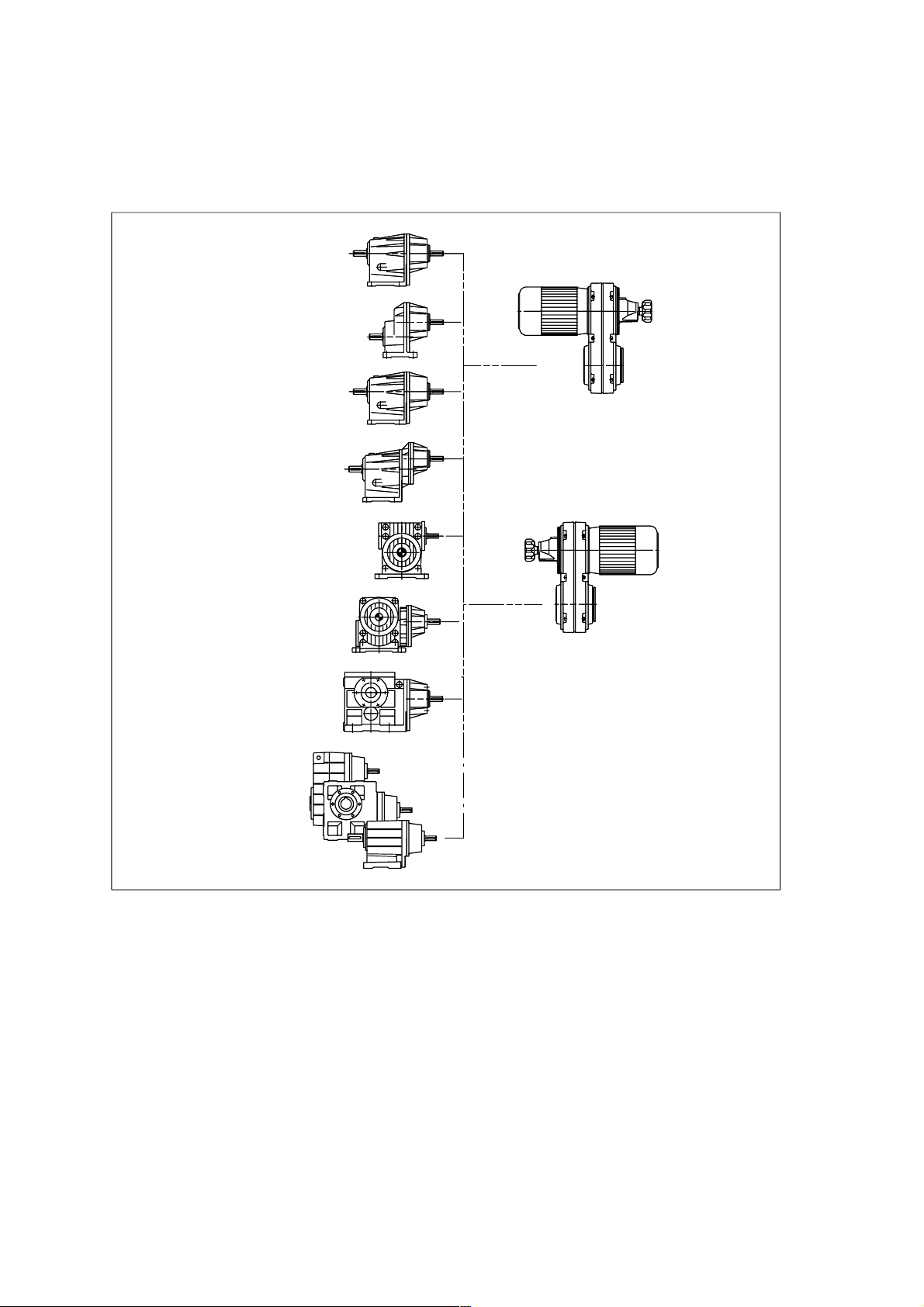
System overview
Show/Hide Bookmarks
12.600.LL
12.601.LL
12.602.LL
12.603.LL
!
&
52.154.LL
"
52.116.LL
#
12.503.LL
$
%
GLL
Helical gearbox i=1 # Helical worm gearbox
Single-stage helicalgearbox $ Helical bevel gearbox
Two-stage helical gearbox % Series GLL gearboxes
'
K11.0311/1
! Three-stage helical gearbox & Simplabelt variable speed drive for
" Wormgearbox compactunits inU-design
l
' Simplabelt variable speed drive for
compact units in Z-design
BA S’belt KEEN 1.0
3
Page 4

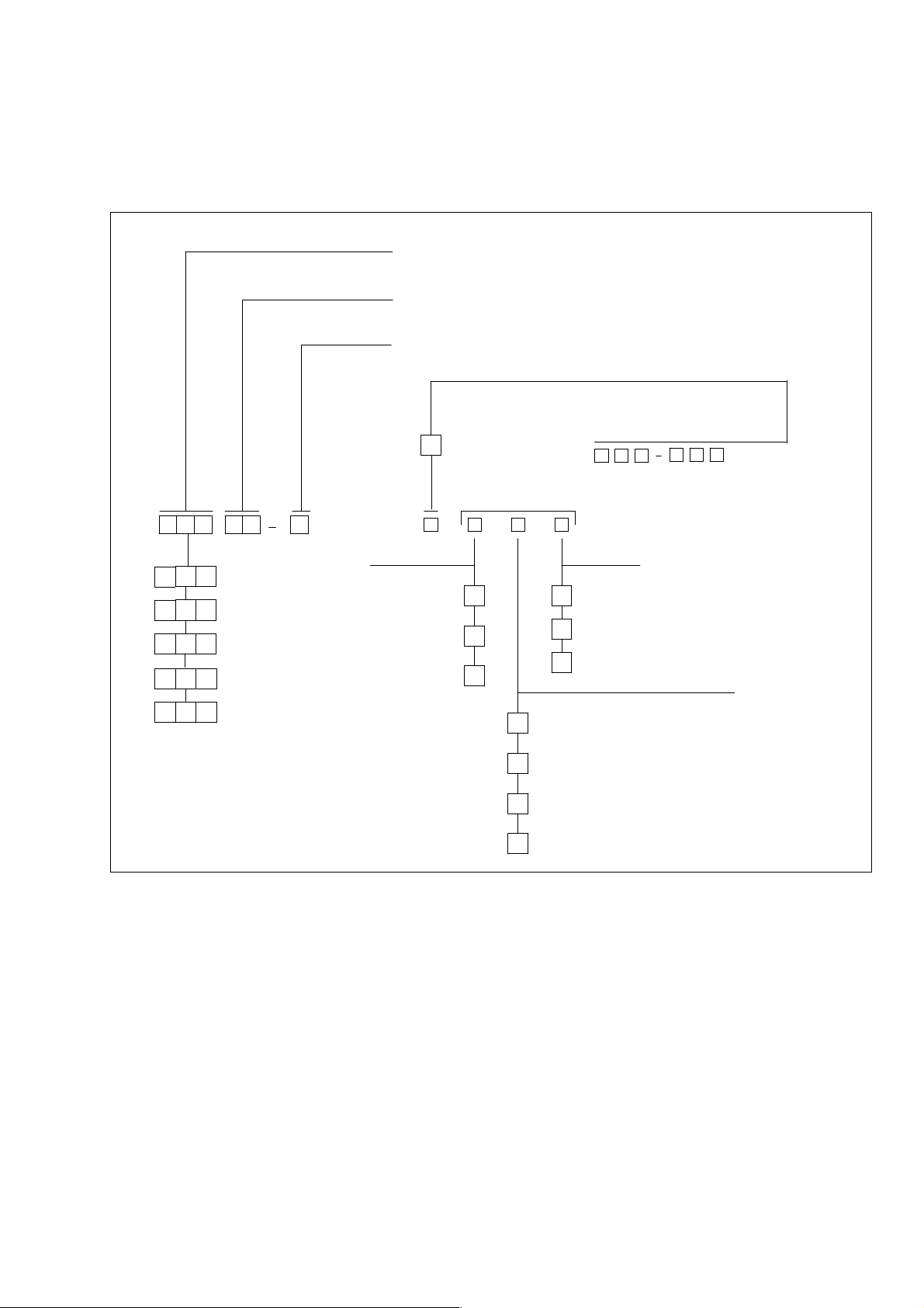
Type code
Show/Hide Bookmarks
11. 432 . 20 . 16 . 2
Type 11.432 (example)
Compact unit in U-design with two-stage helical gearbox
Sizes of the compact unit 10, 13, 16, 20, 25, 31, 40
Reduction gearbox sizes
!!!!
""""
####
Helical gearboxes 08, 10, 12, 16, 20, 25, 32
Worm gearboxes 04, 05, 06, 08, 10, 12
Helical worm gearboxes 15, 19, 24, 30
! Motor code
" Reduction gearbox design
0 = Helical gearbox i=1
1 = Single-stage helical gearbox
2 = Two-stage helical gearbox
3 = Three-stage helical gearbox
5 = Worm gearbox
6 = Helical worm gearbox
7 = Helical bevel gearbox
# Design of the compact unit
3=U-design
4=Z-design
Nameplate
The nameplate for the whole drive is attached to the housing of the modular unit.
4
BA S’belt KEEN 1.0
l
Page 5
Product key
Show/Hide Bookmarks
Gear box t ype
Gear box si ze
Number of stag es
Input design
K12.0546
G
G
G
G
G
S
K
S
F
K
Helical gearbox
T
Low- profile gearbox
L
Helical-bevel gearbox
S
Bevel gearbox
R
Helical-wormgearbox
S
K
Shaf t
Solid shaft
Hollow shaft
Hollow shaft with
shrink di sk
Compact Units
Output design
V
H
S
A
B
C
D
R
K
Drive size
Output
wit hout fl ange
wit h fla nge (trough- holes)
L
wit h fla nge (thre aded-hol es)
Housin g w ith pitch circle
wit h centering and foot
wit h foot (without ce nteri ng)
wit h centering (without f oot)
wit hout centeri ng (without foot )
*
Product key with gearboxes of product family GLL
* according to product family
l BA S’belt KEEN 1.0
5
Page 6

Contents
Show/Hide Bookmarks
1 Preface and general information 8...........................................
1.1 How to use these Operating Instructions 8................................................
1.1.1 Terminology used 8.........................................................
1.2 Contents of delivery 8...............................................................
1.3 Lenze-drive systems 9..............................................................
1.3.1 Labelling 9................................................................
1.3.2 Application as directed 9.....................................................
1.3.3 Legal regulations 9..........................................................
2 Safety information 10......................................................
2.1 Personnel responsible for safety 10......................................................
2.2 General safety information 10..........................................................
2.3 Layout of the safety information 11......................................................
3 Technical data 12.........................................................
3.1 Product features 12.................................................................
3.1.1 Design 12.................................................................
3.1.2 Method of operation 12.......................................................
3.2 Weights 14........................................................................
3.3 Operating conditions 14..............................................................
3.3.1 Temperatures 14............................................................
3.3.2 Ambient conditions 14........................................................
4 Installation 15............................................................
4.1 Storage 15........................................................................
4.2 Installation 15......................................................................
4.2.1 Preparation after long storage 15................................................
4.2.2 General information on the assembly of drive systems 15..............................
4.3 Electrical connection 16..............................................................
4.3.1 Connection of the main motor 16................................................
4.3.2 Connection of the remote-control motor 16.........................................
4.3.3 Connection of the speed measuring unit 17.........................................
5 Commissioning and operation 19.............................................
5.1 Before you start 19..................................................................
5.2 During operation 19.................................................................
6
BA S’belt KE EN 1.0
L
Page 7

Contents
Show/Hide Bookmarks
6 Maintenance 20..........................................................
6.1 Maintenance intervals 20.............................................................
6.2 Maintenance operations 20............................................................
6.2.1 Replacing the V-belt 20.......................................................
6.2.2 Adjustment of output speed 21..................................................
6.2.3 Replacing the lubricant at gearboxes 22...........................................
6.3 Repair 23.........................................................................
6.4 Spare-parts list 254..................................................................
6.5 Order form 25......................................................................
7 Troubleshooting and fault elimination 26.......................................
8 Waste disposal 26.........................................................
Manufacturer’s Certification
Service addresses
L BA S’belt KE EN 1.0
7
Page 8

Preface and general information
Show/Hide Bookmarks
1 Preface and general information
1.1 How to use these Operating Instructions
l These operating instructions are intended for safety-relevant operations on and with the
Simplabelt compact units. They contain safety information which must be observed.
l All personnel working on and with the compact units must have the Operating Instructions
available and observe the information and notes which are relevant for them.
l The Operating Instructions must always be complete and perfectly readable.
1.1.1 Terminology used
Compact unit
For ”Simplabelt compact unit” the term ”compact unit” will be used in the following text.
Drive system
Fordrivesystemswith Simplabelt compactunits and other Lenzedrivecomponentstheterm”drive
system” willbe used in thefollowing text.
1.2 Contents of delivery
l The drive systems are combined individuallyaccording to a modular design. The contents of
delivery can be obtained from the pertinent papers.
l After receipt of the supply, check immediately whether the contents of delivery correspond to
the accompanying papers. Lenze does not grant any warranty for subsequent claims.
Immediately claim:
– visible transport damages to the forwarder
– visible defiencies/incompleteness to the responsible Lenze branch office or agency.
8
BA S’belt KEEN 1.0
l
Page 9

Preface and general information
Show/Hide Bookmarks
1.3 Lenze-drive systems
1.3.1 Labelling
l Lenze drive systems are uniquely designated by the content of their nameplates.
l Manufacturer:
Lenze GmbH & Co KG
Postfach 10 13 52
D-31763 Hameln
1.3.2 Application as directed
l Lenze drive systems
– are intended for use in machineryand systems
– must only be used for the purposes ordered and confirmed
– must only be operated under the ambient conditions prescribed in these operating
instructions
– must not be operated beyond their corresponding power limits
Anyother use shall be deemed inappropriate!
1.3.3 Legal regulations
Liability
l The information, data, and notes in the Operating Instructions were on the state of the art at
the time of printing. Claims about drive systems already supplied cannot be made from the
information, illustrations, and descriptions.
l We do not accept any liability for damages and operating interference caused by:
– inappropriate use
– unauthorized modifications to the drive system
– improper working on and with the drive system
– operating mistakes
– disregarding the Operating Instructions
Warranty
l Conditions of warranty: see terms of sale and delivery of Lenze Drive Systems GmbH.
l Warranty claims must be made to Lenze immediately after detecting the deficiency or fault.
l The warranty is void where liability claims cannot be also made either.
l BA S’belt KEEN 1.0
9
Page 10

Safety information
Show/Hide Bookmarks
2 Safety informat ion
2.1 Personnel responsibl e for safety
Operator
l An operator is any natural or legal person who uses the drive system or on behalf of whom
the drive system is used.
l The operator or his safety officer must ensure
– that all relevant regulations, instructions and legislation are observed.
– that only qualified personnel works with and on the drive system.
– that the personnel have the operating instructions available for all corresponding
operations.
– that non-qualified personnel are prohibited from working with and on the drive system.
Skilled personnel
Skilled personnel are persons who are - because of their education, experience, instructions, and
knowledge about corresponding standards and regulations, rules for the prevention of accidents,
and operatingconditions- authorizedbythepersonresponsibleforthe safetyof theplant toperform
the required actions and who are able to recognize potential hazards
(seeIEC364, definition for skilled personnel) .
2.2 General safety information
l This safety information is not claimed to be complete. In case of questions and problems
please contact your Lenze representative.
l At the time of supply thedrive system meets the state of the art and ensures basically safe
operation.
l The drive system is a source of danger for persons, for thedrive system itself, and for other
material assets of the operator, if
– non-qualified personnel work with and on the drive system.
– the drive system is used inappropriately.
l The drive systems must be designed such that they perform their functions after proper
installation and with application as directed in non-interfered operation and that they do not
cause hazards for persons. This also applies for their interaction with the complete plant.
l Make sure by appropriate measures that in case of failure of the drive system no material
damage is caused.
l Operate the drive system onlywhen in proper state.
l Retrofittings, modifications, or redesigns of the drive system are basically prohibited. In any
case, Lenze must be contacted.
l The compact units must not be adjusted in standstill.
10
BA S’belt KEEN 1.0
L
Page 11

2.3 Layout of the safety information
electricalvoltage
Conse
quencesifdisregarded:
d
r
o
rmo
dange
r
C
o
ifd
isr
r
ded
Show/Hide Bookmarks
l All safety information in these operating instructions has a uniform design:
Signalwort!
Hinweistext
– The icon designates the kind of danger.
– The signal word designates the severeness of the danger.
– The notes describe the danger and suggest how to avoid the danger.
Warning of personal injury
Icons used Signal words
Warning of ha zardous
Danger Wa r n s o f imminant danger.
Safety information
Warning of a general
ange
Warning of a general
danger
Warning! Wa r n s o f a potential, very hazardous situation.
Caution! Wa r n s o f a potential, hazardous situation.
Warning of material damage
Icons used Signal words
Stop! Wa r n s o f potential material damage.
Other information
Icons used Signal words
Note! Designates a general, useful note .
Death or most severe injuries
Consequences if disregarded:
Death
Light or minor injuries.
Consequences if disregarded:
Damage fo t he drive syste m/device or its e nvironment.
If you observe it, handling of the drive system/device is made easier.
nsequences
st severeinjuries
ega
:
L BA S’belt KEEN 1.0
11
Page 12

Technical data
Show/Hide Bookmarks
3 Technical data
l The most important data are indicated on the nameplate.
l Further technical data are listed in the product catalogues.
3.1 Product features
3.1.1 Design
Drive systems have a modular design. They consist of:
l Simplabelt attachment units
l Reduction gearboxes (helical gearboxes, worm gearboxes, helical worm gearboxes, or
helical bevel gearboxes)
l Three - phase AC motors to IEC standard
l Adjustment facilities
l Speed displays
3.1.2 Method of operation
(seeFig. 1 and Fig. 2 )
The three-phase AC motor (11BA)drives the mechanically adjustable variable speed pulley (1BA)
whichdrives the spring-loaded variablespeed pulley( 2BA)via theV-belt (3BA). Thispulley is fitted
onto thedrivingshaft of thereduction gearbox (12BA). Thevariablespeed pulleysandthe V-belt are
covered by the housings (4BA and 5BA).
The speed is adjusted via the adjustment facilities (6BA, 7BA, 8BA), i.e. by turning the handwheel
or operating the adjusting motor to move thepulley flange of themechanically adjustable variable
speed pulley(1BA)inthe axialdirection. The speed is indicated bymeans of thespeed indicatorin
the handwheel or a DC tacho or an impulse recorder and a display.
12
BA S’belt KEEN 1.0
L
Page 13

Technical data
Show/Hide Bookmarks
2 11BA 1.16 1.15 1BA 6BA 7BA 8BA
1
3BA
12BA 2BA 4BA 5BA
Fig. 1 Simplabelt compact unit, U-design
8BA 7BA 6BA 1BA 1.15 1.16 11BA 2
K11.0365/1
1
3BA
Fig. 2 Simplabelt compact unit, Z-design
L BA S’belt KEEN 1.0
12BA
4BA 5BA 2BA
K11.0365/1
13
Page 14

Technical data
Show/Hide Bookmarks
3.2 Weights
Compact Units Weight [kg] Compact Units Weight [kg]
11.4L1.10
11.4L2.10
11.4L3.10
11.4L5.10
11.4L1.13
11.4L2.13
11.4L3.13
11.4L5.13
11.4L6.13
11.4L7.13
11.4L1.16
11.4L2.16
11.4L3.16
11.4L5.16
11.4L6.16
11.4L7.16
11.4L1.20
11.4L2.20
11.4L3.20
11.4L5.20
11.4L6.20
11.4L7.20
<25
<25
<40
<25
<60
<60
<80
<60
<60
<60
< 100
< 100
< 125
< 100
< 100
<125
< 100
< 125
< 250
< 150
< 150
< 200
11.431.25
11.432.25
11.433.25
11.435.25
11.436.25
11.437.25
11.431.31
11.432.31
11.433.31
11.437.31
11.431.40
11.432.40
11.437.40
< 200
< 500
< 400
< 250
< 300
<400
< 400
< 400
< 500
< 500
< 1000
< 1000
< 1000
3.3 Operating conditions
3.3.1 Temperatures
The permissible temperature range is determined by the following:
l Thetorquetobetransmitted(→ dimensioning).
l The lubricant specification of the gearbox considering the oil temperature expected during
operation (see nameplate and/or Operating Instructions of the gearbox).
l The thermal class of the motor considering the motor temperature expected during operation
(seenameplate and Operating Instructions of the motor).
The operating temperature is determined by the power loss, the ambient temperature and the
cooling system!
3.3.2 Ambient conditions
l Gearboxes are protected against dust and spray water.
l Motors according to their enlosure (seenameplate and/or Operating Instructions of the
motor).
l Ambient media - especially chemically aggressive - can destroy shaft seals and coatings
(plastics) . Abrasive media may endanger shaft seals.
14
BA S’belt KEEN 1.0
L
Page 15

4 Installation
Show/Hide Bookmarks
Caution!
Transport the driveonly with transport equipment or hoistswhich are suitable for this load. Ensure
asafefixing.Avoidshocks!
The units in Z-design are not stable! Ensure proper support!
4.1 Storage
If you do not install the gearbox immediately, ensure the appropriate storage conditions.
l Up to one year:
Without special measures in dry, dust-free rooms which are protected against sunlight.
– Store gearbox with ventilation so that the breather screw is located at the top.
– Shafts and bright surfaces are delivered with protection against corrosion.
l Remove V-belts when storing the units for more than three months.
l More than a year:
Please contact the factory.
Installation
4.2 Installation
4.2.1 Preparation after long storage
Carefully remove the anti-corrosion agents from output shafts and flange surfaces.
4.2.2 General information on the assemblyof drive systems
l Take the necessary safety measures prior to any operations:
– Disconnect the machine from the mains, ensurestandstill of the machine and avoid any
machine movement.
– Check the proper state of the drive system. Never install and set-up damaged drive
systems.
– Check the combination of drive function and machine function. Check the direction of
rotation.
l The mounting surfaces must be even, without torsion, and free of vibrations.
l Align the drive system on the mounting surfaces exactly with themachine shaft to be driven.
l Ensurethat the assembly is without torsion, to avoid additional load.
l Compensate minor misalignment by using suitable flexible couplings.
l Upport the reaction torque appropriately.
l Fixings of accessories and attachments must be secured against loosening.
l We recommend bonding screw connections.
L BA S’belt KEEN 1.0
15
Page 16

Installation
Show/Hide Bookmarks
Stop!
Thelubricant filling is adapted to themounting position. To avoid damages to thegearbox, do not
change the mounting position indicated on the nameplate.
Caution!
Compact units in Z-design are not stable. Ensure propper support.
4.3 Electrical connection
Danger!
Electrical connections must only be carried out by skilled personnel!
4.3.1 Connection of the main motor
Connect the motor of your drive system according to the notes in the terminal box and the motor
operating instructions.Pleaseobserve the technicaldataonthemotornameplatepos. 2(Fig. 1and
Fig. 2).
4.3.2 Connection of the remote- control motor
Stop!
The remote-control motor must only be operated when the main motor is running. For testing the
functions at standstill, the momentary-contact switches must only be touched briefly.
1. Connect the remote-control motor according to the circuit diagram ( Fig. 3).
2. Check the direction of rotation in inching mode:
– Touch switch S1: the contact pin must move towards the flange.
– Touch switch S2: the contact pin must move in theopposite direction.
– If the pin does not move as indicated, reverse the motor polarity.
3. Check the limit switch:
– Actuate limit switch S3 (n
– Actuate limit switch S4 (n
– The contact pin must not move in either cases.
16
)and touch S1.
2max
)and touch S2.
2min
BA S’belt KEEN 1.0
L
Page 17

F1 Fuse
Show/Hide Bookmarks
K1, K2 Combined contactor relay for phase reversion
(CW or CCW rotation of the adjusting motor)
M1 Remote-control motor
Q1 Main switch
Q2 Motor circuit breaker
S1 Momentary-contact switch “faster”
S2 Momentary- contact switch “slower”
S3 Limit switch (highest spe ed limit)
S4 Limit speed (lowest speed limit)
① Drive motor
② Control phase of drive motor
③ faster
④ slower
Installation
①①①①
②②②②
③③③③
④④④④
K11.0252
Fig. 3 Connection diagram for the electrical remote control
4.3.3 Connection of the speed measuring unit
You can select the speed measuring units. They all can be retrofitted. The speed measuring units
aredelivered withconnectioncables. They are connected according to the user’s application orto
the requirements of the Lenze display units.
Three-phase AC tacho w ith rectification
Thethree-phase AC tacho with rectification generates a voltage which depends on thespeed and
the input resistance of the evaluating unit. The generated voltage can be evaluated via a
superimposed control or Lenze display units.
Suitable Lenze display units:
Analog voltmeter VSC 96 (approx. 5000Ω)
Digital voltmeter Fdi 635-F( > 100 kΩ)
1 Complete tacho
2Cover
3 Tightenning screw
4 Sealing washer
5 Allen screw
6 Stator (must be adjusted concentrically, gap “a”
must not change)
7Cable,1m
25
4
3
6
Fig. 4 Three-phase AC tacho with rectification
L BA S’belt KEEN 1.0
1
7
K11.0340
17
Page 18

Installation
Show/Hide Bookmarks
Fig. 5 Output voltage of the three-phase AC tacho with rectification as a function of the speed and the input resistance of the
display unit
Pulse recorder
The contactless speed measuring works with a rotating punched disk and a fixed pulse recorder.
In connection with a NAMUR input the pulse recorder generates a digital signal.
Suitable Lenze display units:
Analog voltmeter VSC 96 (approx. 5000 Ω)with digital-to-analog converter
Digital display unit ELTA 2000 A
1 Pulse recorder
2 Punched disk
3 Fixing screw
4Cover
K11.0249/1
Fig. 6 Pulse recorder
Technical data:
Housing Stainless steel
Connection cable 2.5 m PVC cable 2 x 0.14mm max. 300 m should be connected
Control circuit DIN 19234 or NAMUR
Auxiliary power/rated value 8.2 V ” 0.5 V / R
Signal volt age >1,2V
18
BA S’belt KEEN 1.0
ss
=1kΩ ”50Ω
i
L
Page 19

5 Commissioning and operation
Show/Hide Bookmarks
Stop!
The drive must only be commissioned by skilled personnel!
5.1 Before you start
Ensurethat the driveis not connected to mains and does not rotateunintentionally . Please check:
l Is the mechnical fixing o.k.?
l Are the electrical connections o.k.?
l For gearboxes with ventilation:
Is the plug removed from the breather screw?
Commissioning
5.2 During operation
Check the drive periodically during operation and take special note of unusual noises or
temperatures, leakages, loose fastening elements, and the state of the electrical cables. If any
interference occurs, proceed according to the troubleshooting list in chapter 7. If it is not possible
to eliminate the interference, please contact the Lenze Service.
Stop!
Never adjust the speed at standstill!
Otherwise, the compact unit will be damaged!
L BA S’belt KE EN 1.0
19
Page 20

Maintenance
Show/Hide Bookmarks
6 Maintenance
6.1 Maintenance intervals
Stop!
With drivesystems: Please observethe maintenance intervals of theother drive components, too!
l Wide V-belts have a natural wear which depends on several factors:
–On-time
– Load type
– Speeds
– Ambient temperature
As a guide value Lenze recommends to check the wide V-belt for wear and fissures every 4 to 6
months and replace it, if necessary.
l Variable speed pulleys are maintenance-free.
Note!
While checking thewide V-belt Lenze recommends to inspect visually the variable speed pulleys.
Check if themovabledisc canbe moved and the state of the disc face. Run-in grooveson the disc
face caused by wear reduces the belt life.
6.2 Maintenance operations
6.2.1 Replacing the V-belt
Stop!
Only use original Simplabelt V-belts!
Disassembly with U-design (see Fig. 1):
1. Activate the drive and accelerate it to max. speed, then switch off the drive and disconnect it
from mains.
2. Loosen 6 screws (1.16; 1.15)and remove the cover (5BA).
3. Completely open the variable speed pulleys (1BA), pull the V-belt (3BA)over the front edge of
the variable speed pulley (1BA)and remove it when turning the variable speed pulley.
20
BA S’belt KEEN 1.0
L
Page 21

Maintenance
Show/Hide Bookmarks
Disassembly with Z-design (see Fig. 2):
1. Activate the drive and accelerate it to max. speed, then switch off the drive and disconnect it
from the mains.
2. Loosen 6 screws (1.16; 1.15). Then push aside the covers (5BA and 4BA) to remove the V-belt
(3BA)from the variable speed pulley (1BA). The three-phase AC motor (5.0)must be
supported.
Assembly (U-design and Z-design)
Note!
With sizes 31 and 40, thespring-loaded variablespeed pulley can be opened by screwing a screw
into the flange (Fig. 7).
Remove the screw after assembly!
only with sizes 31 and 40
Required screw dimensions
Size 31: M6 x 40 (DIN933)
Size 40: M12 x 45 (DIN933)
Fig. 7 Variable speed pulley
1. First place the new V-belt onto the mechanically adjustable variable speed pulley (1BA)and
then draw it over the spring-loaded variable speed pulley (2BA)(see Fig. 1 and Fig. 2).
2. Refix housing (6 screws).
3. Start test running and check the speed limitating and the adjustment of the speed indicators
by means of a hand tacho. A readjustment may be necessary (see chap. 6.2.2).
K11.0265
6.2.2 Adjustment of output speed
L BA S’belt KEEN 1.0
The limit for the output speeds n
indication on the nameplate (pos. 1) may be necessary in the event of increased wear or after the
change of the V-belt (Fig. 1 and Fig. 2).
2min
and n
are factory-set. A readjustment according to the
2max
21
Page 22

Maintenance
Show/Hide Bookmarks
6.2.3 Replacing the lubricant at gearboxes
See Gearbox Operating Instructions.
Stop!
Never adjust the speed at standstill!
Otherwise, the compact unit will be damaged!
It must be observed that the V-belt
l does not run on the hub base (clearly audible running noises).
l does not run over the edge of the variable speed pulley.
Non-observance may lead to damage of the drive (bearing damage, belt damage).
Procedure of electric remote adjustment (Fig. 3)
1. Switc h on the drive motor.
2. First adjust the upper speed limit (n
– Check speed with hand tacho, increase speed to max with switch S1.
– Move limit switch S3 towards the contact pin until it switches audibly.
– Tighten the fixing screws of the limit switch.
3. Afterwards adjust the lower speed limit in the same way (momentary-contact switch S2 and
limit switch S4).
2max
).
Procedure of front and angle adjustment (Fig. 8 and Fig. 9)
1. Switc h on the drive motor.
2. Remove the bottom cover (4)of the adjustment unit.
3. Increase speed to its maximum indicated on the nameplate (pos. 1) (F ig. 1 and Fig. 2) by
means of the handwheel and the hand tacho.
4. Bolt (6)must be screwed in as an end limit.
5. Adjust the minimum speed in the same way and use bolt (5)as a limitation.
6. Remount the cover (4).
Afterwards check with the hand tacho whether the display values of the position indicator at the
handwheel correspond to the actual speed value. If not:
Adjust position indicator
7. Loosen setscrew (7)and remove the position indicator (9).
8. Turn the position indicator (9)until the display value corresponds to the actual value, ensure
that the scale is in position.
9. Refit the position indicator (9)in the handwheel (8)and secure it with the setscrew (7) .
22
BA S’belt KEEN 1.0
L
Page 23

4Cover
Show/Hide Bookmarks
5 Fixing screw
6Bolt
7Setscrew
8 Handwheel
9 Position indicat or
Maintenance
Fig. 8 Front adjustment
4Cover
5 Fixing screw
6Bolt
7Setscrew
8 Handwheel
9 Position indicat or
0 drawing turned by 90°
Fig. 9 Angle adjustment
K 11.0263
K 11.0263/2
6.3 Repair
L BA S’belt KEEN 1.0
Lenze recommends that repairs are carried out by Lenze Service.
23
Page 24

24
Show/Hide Bookmarks
6.4 Spare-parts list
11BA
BA S’belt KEEN 1.0
1BA
3BA
6BA
7BA
9BA
8BA
10BA
Maintenance
L
Fig. 10 Compact unit module
12BA 4BA 5BA 2BA
Page 25

L BA S’belt KEEN 1.0
Show/Hide Bookmarks
6.5 Order form
Recipient: Lenze
Postal code/City:___________________
Fax-no.: ___________________
all G
LL
Sende r
Company __________________________ Customer no. __________________
Street / P.O. Box __________________________ Orderno. ___________________
Postal code/City __________________________ Issued by ___________________
Delivery address __________________________ Phone ___________________
__________________________ Fax ___________________
Invoice recipient*__________________________ Date of delivery_________________
Date _____________ Signature ___________________
* Please indicate if othe r than sender
Item Name Pieces
1BA Variable spe ed pulley (mech. adjustabl e)
2BA Variable speed pulley (spring-loaded)
3BA V- bel t
4BA Housing (gea rbox side)
5BA Housing
6BA Front control
7BA Angula r control
8BA Electric front control
9BA Three -phase tacho
10BA Impulse gene rator
11BA Three-pase motor (see Ope rating Intructions Motor)
12BA Gearbox (see Operating Intructions Gearbox)
Maintenance
LENZE type number: ______________
Order number: ______________
25
Page 26

Troubleshooting and fault elimination
r
d
Show/Hide Bookmarks
7 Troubleshooting and fault elimination
If any disturbance should occur during operation of the drive system, please check the possible
causes using the following table. If the fault cannot be eliminated by means of one of the listed
measures, please contact Lenze Service.
Fau lt Possible cause Remedy
Drive does not start No or faulty connection of main motor Check motor conne ction
Clearly audible running noise V-belt runs on hub base, wrong adj ustment of spee d
Speeds indicated on the nameplate cannot be
eache
Position indicat ed on handwheel does not correspond
to output speed
Motor of electric remotecontrol does not rota te Adjustment spindle is stalling To do t his, re move the plastic plug at the rear side of
limit
Wrong adjustment of spe ed limit Correct adjustment of speed limit
Wrong V-belt Use V-belt which corresponds to compact unit
Wrong assembly of posi tion indicator Assemble position indicator a t adjustment of max.
Correct adjustment of speed limit
output spe ed
the adjustment motor.Loosen via the central thread
of the motor shaft.
26
BA S’belt KEEN 1.0
L
Page 27

Waste disposal
Show/Hide Bookmarks
8 Waste disposal
Help to protect the environment! Packing material can be recycled.
Material? Wh ere t o d isp os e?
Transport material Pallets Return to the manufacturer or forwarder
Packing material Cardboa rd boxes to waste pa per
Lubrica nts Oil, grease Dispose a ccording to the valid regulations
Components Housing: grey ca st iron
Bearings, shafts, gear wheels: steel
Seals/V-belts: special waste
disposal
Plastic to plastic recycling or waste material
Reuse or dispose of wood sha ving
Separate va luable substa nces a nd dispose
L BA S’belt KE EN 1.0
27
Page 28

Manufacturer’s Certification
Show/Hide Bookmarks
M anufacturer’sCertification
Weherewith certify that the below listed products are intended for assembly into
a machine or for assembly with other elements to form a machine.
Commissioning of the machine is prohibited before it is proven that it
corresponds to the EC regulation 98/37/E C.
Product : Type :
Low-profile gearboxes and geared motors GFL
Helical gearboxes and geared motors GST, 12.6LL
Helical bevel gearboxes and geared motors GKS, 12.5LL
Bevel gearboxes and geared motors GKR
Helical worm gearboxes and geared motors GSS, 52.1LL
Gear box es
Lenze GmbH & Co KG
Postfach 10 13 52
D-31763 Hameln
Site : Bösingfeld
Breslauer Straße 3
D-32699 Extertal
Telephone (05154) 82-0
Telefax (05154) 82-15 75
Variable speed belt drives and geared motors G LL-K
11.1LL, 11.2LL, 11.4LL
Variable speed drives with/without gearbox GLL-D
11.7LL
Shaft-mounted gearboxes 12.4LL
Worm gearboxes and geared motors 52.3LL, 52.4LL, 52.5LL
Applied standards and regulations:
EN 292 part 1
EN 292 part 2
Hameln, October 18, 2001
(i. V. Dr. K ie l)
Head of R&D dept. gearboxes
28
BA S’belt KEEN 1.0
l
Page 29

Notes
Show/Hide Bookmarks
L BA S’belt KEEN 1.0
29
Page 30

Notes
Show/Hide Bookmarks
30
BA S’belt KEEN 1.0
L
 Loading...