

Page 1
(13360067)
SC & TC SERIES DYNAMIC BRAKING OPTION (FOR MODELS RATED 0.25 - 10 HP)
INSTALLATION AND OPERATION INSTRUCTIONS
Manual Number: DF01C
The SC & TC Series Dynamic Braking option can be used with all SCD, SCL, SCM, SCN and TCF models, and SCF models with parameter version 306 or higher. The
parameter version is displayed momentarily when power is applied, and also appears on a label on the heatsink (For example: PV312).
WARNING!
Remove power from the drive and wait three minutes before wiring the DB module. Incorrect wiring of the B+ and B- terminals
will result in equipment damage! The B+ terminal on the DB module must be connected to the B+ terminal on the drive, and
the B- terminal on the DB module must be connected to the B- terminal on the drive.
DO NOT make connections to R+ and R- without consulting AC Tech. Damage to the Dynamic Braking module and/or drive
may result.
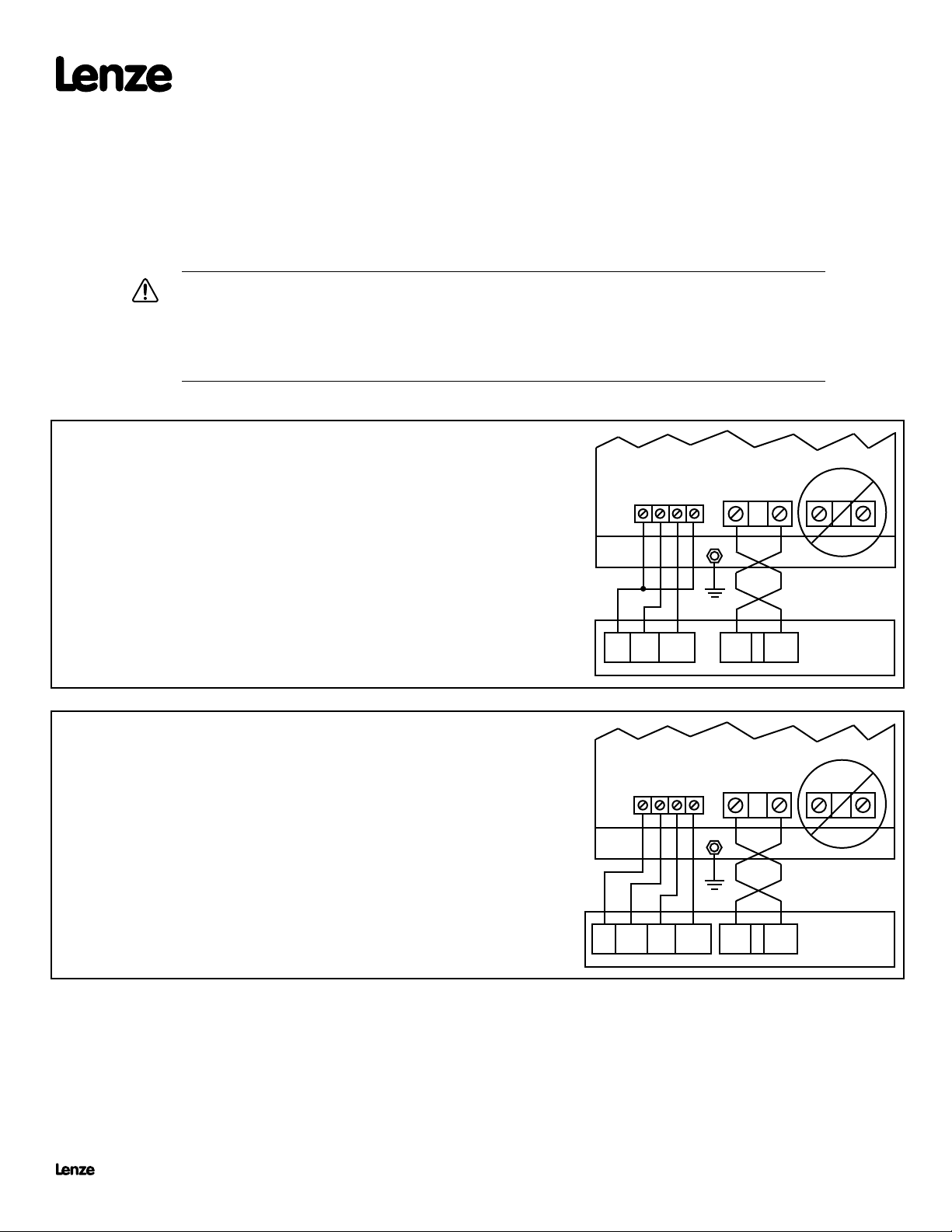
SCD & SCF SERIES DRIVES
PROGRAMMING
1. Set Parameter 09 (TB-31 OUTPUT) to DYNAMIC BRAKING (04).
2. Set Parameter 10 (TB-13A FUNCTION) to DB FAULT (09), or set Parameter 12 (TB-13C
FUNCTION) to DB FAULT (08).
WIRING
The diagram to the right illustrates how the DB module is wired to the SCD & SCF Series drive. In
this diagram, TB-13A is used as the DB FAULT input, but TB-13C could be used instead if TB-13A
is required for another function.
See important wiring NOTES below.
SCL & SCM SERIES DRIVES
PROGRAMMING
1. Set Parameter 12 (TB-13E FUNCTION) to DYNAMIC BRAKING (20).
2. Set Parameter 10 (TB-13A FUNCTION) to INVERSE EXT. FAULT (09), or set Parameter 11
(TB-13B FUNCTION) to INVERSE EXT. FAULT (10).
WIRING
The diagram to the right illustrates how the DB module is wired to the SCL and SCM Series drive. In
this diagram, TB-13A is programmed for INVERSE EXTERNAL FAULT, but TB-13B could be used
instead if TB-13A is required for another function.
See important wiring NOTES below.
DB OPTION MODULE
42
464743
13A2 31
DB OPTION MODULE
42
464743
2
13A13E 11
B -
GND
B - B +
B -
GND
B - B +
B +
B +
R + R -
SCD / SCF
DRIVE
R + R -
SCL / SCM
DRIVE
NOTE 1: Use 18 AWG wire for control connections. Tighten DB module and drive control terminals to a torque of 2 lb-in (0.2 Nm). Overtorque of terminals can result
NOTE 2: Use minimum 14 AWG wire for connections to B+ and B-. Tighten the DB module terminals to a torque of 2 lb-in (0.2 Nm), and tighten the drive terminals
in damage.
to 4.5 lb-in (0.5 Nm). The B+ and B- wires MUST be twisted together and must be less than 12 inches long.
Lenze Americas • 630 Douglas Street • Uxbridge MA 01569 • USA
Sales (800) 217-9100 • Service (508) 278-9100 • www.lenzeamericas.com
DF01C
13360067
Page 2
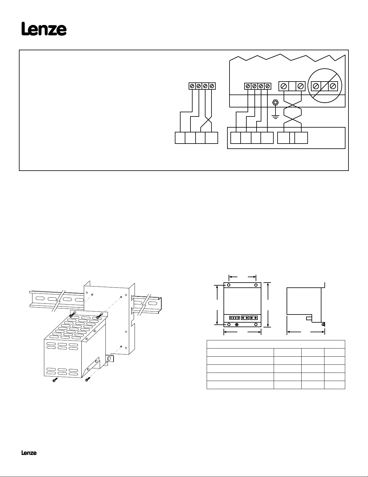
TCF SERIES DRIVES
PROGRAMMING
1. Set Parameter 06 (TB-14 OUTPUT) to DYNAMIC BRAKING (11).
2. Set Parameter 10 (TB-13A FUNCTION) to DB FAULT (10), or set
Parameter 12 (TB-13C FUNCTION) to DB FAULT (08), or set Parameter
49 (TB-13D FUNCTION) to DB FAULT (08).
42
464743
DB OPTION MODULE
B -
42
464743
GND
B +
R + R -
WIRING
The diagrams to the right illustrate how the DB module is wired to the TCF
Series drive, depending on the setting of Parameter 79 (INPUT ASSERTION
LEVEL). In these diagrams, TB-13A is programmed for DB FAULT, but
TB-13C or TB-13D could be used instead if TB-13A is required for another
function.
Be sure to follow the correct wiring diagram based on the setting of
P79!
See important wiring NOTES below.
NOTE 1: Use 18 AWG wire for control connections. Tighten DB module and drive control terminals to a torque of 2 lb-in (0.2 Nm). Overtorque of terminals can result
in damage.
NOTE 2: Use minimum 14 AWG wire for connections to B+ and B-. Tighten the DB module terminals to a torque of 2 lb-in (0.2 Nm), and tighten the drive terminals
to 4.5 lb-in (0.5 Nm). The B+ and B- wires MUST be twisted together and must be less than 12 inches long.
11 414
ACTIVE LOW
P79 set to LOW (02)
13A
11 414
ACTIVE HIGH (default)
P79 set to HIGH (01)
13A
B - B +
TCF
DRIVE
MOUNTING THE DYNAMIC BRAKING MODULE
The diagram below illustrates how to mount the DB Module. The DB Module is compatible with the DIN Rail Mounting Kit option, or can simply be mounted to a at
surface such as an electrical panel.
The DB module is a heat producing device; DO NOT mount the DB module below the drive! The DB module must be mounted above or to the side of the drive.
DIN RAIL
DB MODULE
BRACKET
4.1"
206, 209, 406, 409, 509 0.25 - 1.5 3.1 3.1
214, 215, 414, 415, 514, 515 7.5 - 10 4.2 6.7
2.0"
4.6"
W
DIMENSIONS (inches)
MODEL 845- HP W D
211, 411, 511 2 - 3 3.1 4.3
213, 413, 513 5 3.1 5.6
D
Lenze Americas • 630 Douglas Street • Uxbridge MA 01569 • USA
Sales (800) 217-9100 • Service (508) 278-9100 • www.lenzeamericas.com
DF01C
13360067
 Loading...