

Page 1
BA 13.0008 − EN
.5ôE
Ä.5ôEä
Operating Instructions
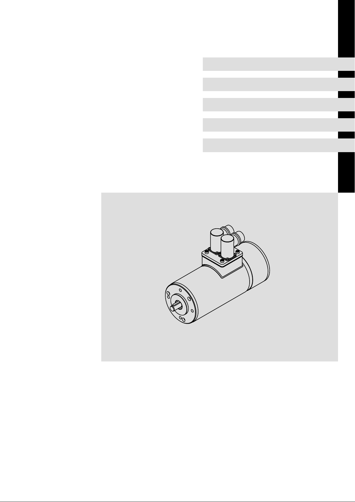
SDSGA
Inverter−optimised asynchronous motors
l
Page 2

, Please read these instructions before you start working!
Follow the enclosed safety instructions.
Document history
Material No. Version Description
409413 1.0 03/1999 TD09 First edition for pilot series
409413 1.1 04/2001 TD09 Chapter 3.2: Extension of application conditions
All chapters: Revised
452930 1.2 04/2002 TD09 Extended by chapter 5.2.1, type and quantity of lubricant
13209536 2.0 04/2007 TD09 Complete revision extended by gearbox type SPL 120
.5ôE 2.1 05/2009 TD09 Change of address
0Fig. 0Tab. 0
0Fig. 0Tab. 0
2
l
BA 13.0008 − EN 2.1
Page 3
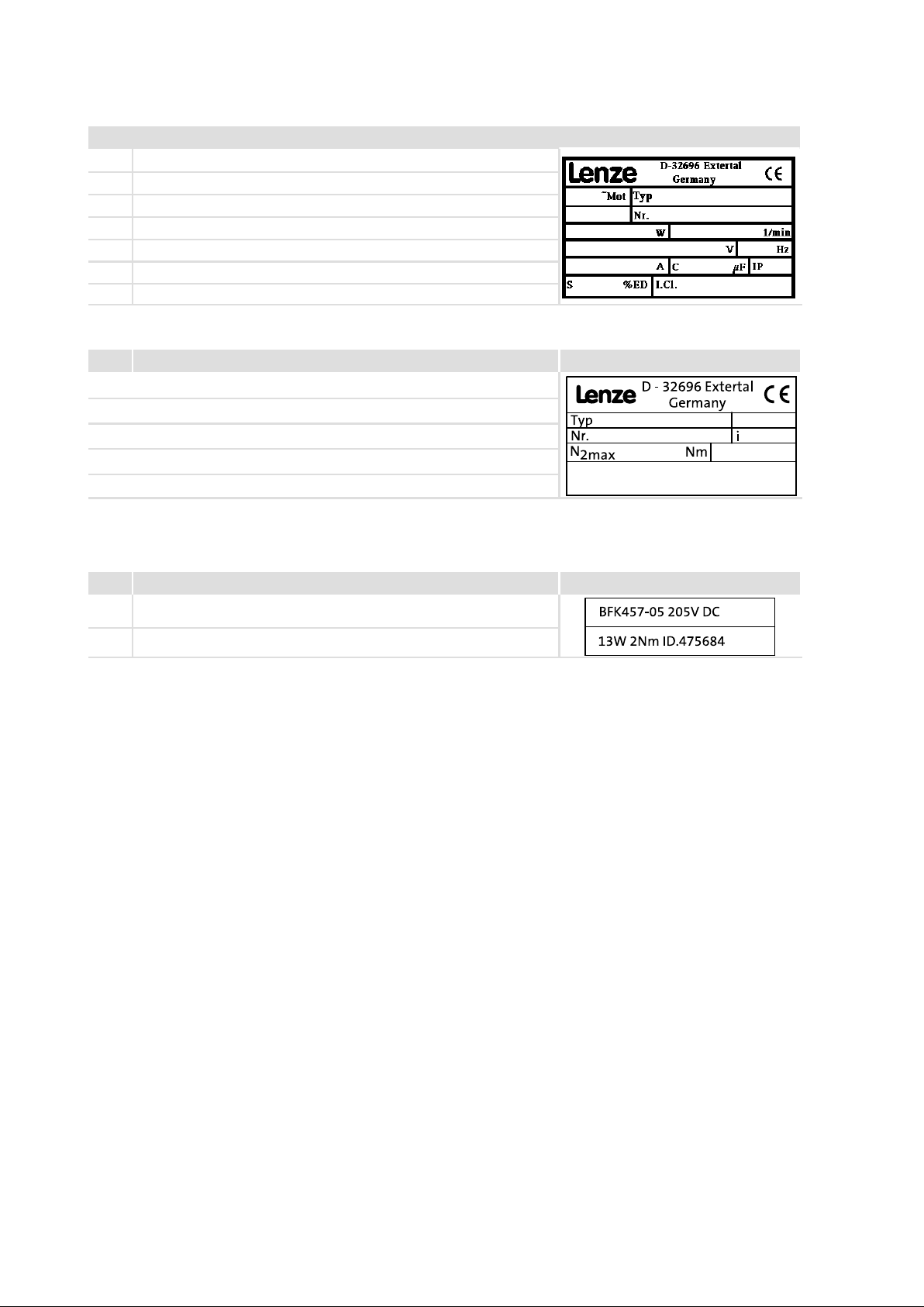
Nameplates
product series SDSLL
Field Contents Example
1 Manufacturer CE identification
2 Type of current Motor type
3 Date of manufacture Commission No.
4 Rated power (W) Rated speed (1/
5 Rated voltage (V) Rated frequency (Hz)
6 Rated current (A) Rated torque (mF) Type of protection (IP)
7 Operating mode Thermal class Material No.
min
)
Gearboxes
Field Contents Example
1 Manufacturer CE identification
2 Gearbox type
3 Commission No. Ratio
4 Torque M2 in Nm
5
Brakes
Reference to installed brake
Field Contents Example
1 Brake type/size Voltage
2 Electric power Torque ID No.
BA 13.0008 − EN 2.1
l
3
Page 4

Type code
Inverter−optimised three−phase AC motors S D S L A LL LLL − L L
0
1
2
3
4
5
6
7
8
Legend for SDLGL type code
0 Product group S Small drives
1 Current type D Three−phase AC
2 Ventilation S Self ventilation (cooling by convection and radiation)
3 Design/housing G
4 Machine type A Asynchronous machine
5 Built−on accessories AG
6 Frame size
7 Overall length
8 Number of pole pairs
Smooth housing and round
R
Ribbed housing, round
Absolute value encoder
BA
Brake and sin/cos absolute value encoder or SSI absolute value encoder
BG
Brake, resolver and incremental encoder
BI
Brake and incremental encoder (pulse encoder)
BR
Brake
BS
Brake and resolver
BW
Brake, resolver and absolute value encoder
B
Brake, encoder prepared
G
No brake, encoder prepared
XX
No brake, no encoder
IG
Incremental encoder (pulse encoder)
RS
Resolver
4
l
BA 13.0008 − EN 2.1
Page 5

Contents i
1 Preface and general information 6 . . . . . . . . . . . . . . . . . . . . . . . . . . . . . . . . . . . . . . . . . . . .
1.1 About these Operating Instructions 6 . . . . . . . . . . . . . . . . . . . . . . . . . . . . . . . . . . . . .
1.1.1 Terminology used 6 . . . . . . . . . . . . . . . . . . . . . . . . . . . . . . . . . . . . . . . . . . . . .
1.1.2 Scope of supply 6 . . . . . . . . . . . . . . . . . . . . . . . . . . . . . . . . . . . . . . . . . . . . . .
1.2 Legal regulations 7 . . . . . . . . . . . . . . . . . . . . . . . . . . . . . . . . . . . . . . . . . . . . . . . . . . . . .
2 Safety instructions 8 . . . . . . . . . . . . . . . . . . . . . . . . . . . . . . . . . . . . . . . . . . . . . . . . . . . . . . . . .
2.1 Personnel responsible for safety 8 . . . . . . . . . . . . . . . . . . . . . . . . . . . . . . . . . . . . . . . .
2.2 Residual hazards 9 . . . . . . . . . . . . . . . . . . . . . . . . . . . . . . . . . . . . . . . . . . . . . . . . . . . . .
2.3 Safety instructions for low−voltage machinery 9 . . . . . . . . . . . . . . . . . . . . . . . . . . . .
2.4 Definition of notes used 12 . . . . . . . . . . . . . . . . . . . . . . . . . . . . . . . . . . . . . . . . . . . . . . .
3 Technical data 13 . . . . . . . . . . . . . . . . . . . . . . . . . . . . . . . . . . . . . . . . . . . . . . . . . . . . . . . . . . . .
3.1 Rated data 13 . . . . . . . . . . . . . . . . . . . . . . . . . . . . . . . . . . . . . . . . . . . . . . . . . . . . . . . . . .
3.1.1 Shaft loads 14 . . . . . . . . . . . . . . . . . . . . . . . . . . . . . . . . . . . . . . . . . . . . . . . . . .
3.2 General data and operating conditions 15 . . . . . . . . . . . . . . . . . . . . . . . . . . . . . . . . . .
3.2.1 Other application conditions 16 . . . . . . . . . . . . . . . . . . . . . . . . . . . . . . . . . . .
4 Mechanical installation 18 . . . . . . . . . . . . . . . . . . . . . . . . . . . . . . . . . . . . . . . . . . . . . . . . . . . . .
4.1 Transport, storage and installation 18 . . . . . . . . . . . . . . . . . . . . . . . . . . . . . . . . . . . . . .
4.2 Site 19 . . . . . . . . . . . . . . . . . . . . . . . . . . . . . . . . . . . . . . . . . . . . . . . . . . . . . . . . . . . . . . . .
5 Electrical installation 20 . . . . . . . . . . . . . . . . . . . . . . . . . . . . . . . . . . . . . . . . . . . . . . . . . . . . . . .
5.1 Attachments 21 . . . . . . . . . . . . . . . . . . . . . . . . . . . . . . . . . . . . . . . . . . . . . . . . . . . . . . . .
5.2 Gearbox mounting 21 . . . . . . . . . . . . . . . . . . . . . . . . . . . . . . . . . . . . . . . . . . . . . . . . . . .
5.2.1 Table of lubricants 22 . . . . . . . . . . . . . . . . . . . . . . . . . . . . . . . . . . . . . . . . . . . .
5.2.2 Connection plan for SDSGALL inverter motor 24 . . . . . . . . . . . . . . . . . . . . . .
6 Commissioning 26 . . . . . . . . . . . . . . . . . . . . . . . . . . . . . . . . . . . . . . . . . . . . . . . . . . . . . . . . . . .
6.1 Before switching on 26 . . . . . . . . . . . . . . . . . . . . . . . . . . . . . . . . . . . . . . . . . . . . . . . . . .
6.2 During operation 27 . . . . . . . . . . . . . . . . . . . . . . . . . . . . . . . . . . . . . . . . . . . . . . . . . . . . .
7 Maintenance/repair 28 . . . . . . . . . . . . . . . . . . . . . . . . . . . . . . . . . . . . . . . . . . . . . . . . . . . . . . .
7.1 Temperature monitoring 28 . . . . . . . . . . . . . . . . . . . . . . . . . . . . . . . . . . . . . . . . . . . . . .
7.2 Repair 29 . . . . . . . . . . . . . . . . . . . . . . . . . . . . . . . . . . . . . . . . . . . . . . . . . . . . . . . . . . . . . .
8 Troubleshooting and fault elimination 30 . . . . . . . . . . . . . . . . . . . . . . . . . . . . . . . . . . . . . . .
BA 13.0008 − EN 2.1
l 5
Page 6

1
Preface and general information
About these Operating Instructions
Terminology used
1 Preface and general information
1.1 About these Operating Instructions
ƒ These Operating Instructions inform about safety−relevant working on and with
inverter−optimised motors of type SDS. They contain safety instructions which must
be observed to enable trouble−free operation.
ƒ All persons working on and with the inverter−optimised motors of type SDS must
have the Operating Instructions available and observe the information and notes
relevant for them.
ƒ The Operating Instructions must always be complete and perfectly readable.
1.1.1 Terminology used
Term In the following text used for
Motor Inverter−optimised motor of type SDS
Drive system Drive system with inverter−optimised motor of type SDS or other Lenze
1.1.2 Scope of supply
ƒ Short description
After receipt of the delivery, check immediately whether the items delivered match the
accompanying papers. Lenze does not accept any liability for deficiencies claimed
subsequently.
Claim
ƒ visible transport damage immediately to the forwarder.
ƒ visible deficiencies/incompleteness immediately to your Lenze representative.
drive components
6
l
BA 13.0008 − EN 2.1
Page 7

Preface and general information
Legal regulations
Scope of supply
1
1.2 Legal regulations
Labelling
Application as
directed
Liability l The information, data, and notes in these instructions were up to date at the time of printing. Claims
Warranty l Terms of warranty: see terms of sales and delivery of Lenze GmbH & Co KG Kleinantriebe.
Disposal
In−house
transport
Storage
conditions
Nameplate Manufacturer
Lenze products are clearly labelled and defined by the
indications on the nameplates.
Drive products
l must only be operated under the conditions prescribed in these Instructions.
l must only be used for the ordered and acknowledged application conditions.
l meet the protection requirements of the EC "Low−Voltage Directive".
l are not machines in the sense of the EC Machine Directive.
l must not be used at powers higher or lower than indicated in these Instructions.
Drive systems with SDS motors
l meet the EC Directive "Electromagnetic compatibility" if they are installed according to the specifications
of the CE−typical drive system.
l are applicable:
– on public and non−public mains,
– in industrial as well as residential and commercial premises.
l The end user is responsible for adhering to the EC directives in the machine application.
Any other use shall be deemed inappropriate!
referring to motors which have already been supplied cannot be derived from the information, illustrations
and descriptions.
l The process−related notes and circuit sections used in these instructions are suggestions whose suitability
for the respective application must be checked. Lenze assumes no guarantee for the suitability of the listed
procedures and circuit samples.
l These operating instructions describe the product features without guaranteeing them.
l No liability shall be accepted for damage and downtimes resulting from:
– non−observance of the operating instructions
– unauthorised changes or modifications to the motors
– operating errors
– improper work on and with the motors.
l Warranty claims must be made to Lenze immediately after detecting the deficiency or fault.
l The warranty is void in all cases in which liability claims cannot be made.
Material Recycle Dispose
Metal D −
Plastic D −
Assembled PCBs − D
l Transport the motors free of vibration.
l Avoid heavy shocks.
l If possible, use manufacturer’s packaging for transport.
Cushioned bag ensures:
– dust protection
– moisture protection
– mechanical protection
l Storage:
– free of vibration
if a certain risk of vibration exists, we recommend to rotate the rotor once per week
– dry, in a non−aggressive environment
– free of dust
– free of extreme temperature changes
l Corrosion:
– Steel parts are corrosion−protected when being delivered. Do not remove the protection! Check it every
three months and, if necessary, renew it.
Lenze GmbH & Co KG
Kleinantriebe
Postfach 10 13 52
D−31763 Hameln
BA 13.0008 − EN 2.1
l
7
Page 8

2
Safety instructions
Personnel responsible for safety
2 Safety instructions
2.1 Personnel responsible for safety
Operator
ƒ An operator is any natural or legal person who uses the drive system or on behalf of
whom the drive system is used.
ƒ The operator or his safety officer must ensure
– that all relevant regulations, instructions and legislation are observed.
– that only qualified personnel work with and on the drive system.
– that the personnel have the Operating Instructions available for all corresponding
operations.
– that non−qualified personnel are prohibited from working with and on the drive
system.
Skilled personnel
Skilled personnel are persons who − because of their education, experience, instructions,
and knowledge about corresponding standards and regulations, rules for the prevention
of accidents, and operating conditions − are authorised by the person responsible for the
safety of the plant to perform the required actions and who are able to recognise potential
hazards.
(See IEC 364, definition of skilled personnel)
8
l
BA 13.0008 − EN 2.1
Page 9

2.2 Residual hazards
Protection of persons The motor surfaces can become very hot. Danger of burns when touching!
Device protection Built−in thermal detectors are not a full protection for the machine.
Fire protection Fire hazard
Safety instructions
Residual hazards
l Install a guard, if necessary.
High−frequency voltages can be capacitively transferred to the motor housing
through the inverter supply.
l Carefully earth the motor housing.
Danger of unintentional starting or electrical shocks
l Perform connection work only in the de−energised state, only with motor
in standstill.
l Built−in brakes are not fail−safe brakes.
l If necessary, limit the maximum current, perform a function block
interconnection with disconnection after a few seconds of operation with I
> I
, particularly if a danger of blocking exists.
N
l The integrated overload protection does not prevent overload under all
conditions!
Built−in brakes are not fail−safe brakes .
l Speed reduction is possible.
Fuses are not a motor protection.
l Use current−dependent motor protection switches for average operating
frequency
l Use built−in thermal detectors at high operating frequency.
Excessive torques lead to a break of the motor shaft or demagnetisation
l Do not exceed the maximum torques according to the catalogue.
Lateral forces from the motor shaft are possible.
l Perfectly align shafts of motor and driving machine to each other.
l Speeds >3000 min
l Prevent contact with combustible substances.
−1
destroy the motor.
2
2.3 Safety instructions for low−voltage machinery
in conformity with the Low−Voltage Directive 73/23/EEC
1. General
Low−voltage machines have dangerous, live and rotating parts as well as possibly hot
surfaces. All operations serving transport, connection, commissioning and maintenance
are to be carried out by skilled, responsible technical personnel (observe prEN 50110−1/
VDE 0105; IEC 364). Improper handling can cause severe injuries or material damage.
2. Application as directed
These low−voltage machines are intended for industrial and commercial installations.
They comply with the harmonised standards of the series EN60034 (VDE 0530). Their use
in hazardous areas is prohibited unless they are expressly intended for such use (follow
additional instructions).
The enclosures £ IP 23 are by no means intended for outdoor use. Air cooled designs are rated
for ambient temperatures between −20°C and +40°C and altitudes of £ 1000 m amsl. Check
indications on the nameplate and, if other observe them. The conditions on site must
correspond to all nameplate data.
Low−voltage machines are components for installation in machinery as defined in the
Machinery Directive 89/392/EEC. Commissioning is prohibited until conformity of the end
product with this Directive has been established (observe i.a. EN 60204−1).
BA 13.0008 − EN 2.1
l
9
Page 10

2
Safety instructions
Safety instructions for low−voltage machinery
3. Transport, storage
The forwarder must be informed directly after receipt of the goods about all damage or
deficiencies; if necessary, commissioning must be stopped. Tighten screwed−in ring bolts
before transport. They are designed for the weight of the low−voltage machine, do not
apply extra loads. If necessary, use suitable and adequately dimensioned means of
transport (e.g. rope guides).
Remove the shipping brace before commissioning. Reuse it for further transports. For
storage of low−voltage machines ensure a dry, dust−free and low−vibration (v rms
£O.2mm/s) environment (damage while being stored). Measure the insulation resistance
before commissioning. If the values are £1k per volt of rated voltage, dry the winding.
4. Installation
Ensure an even surface, solid foot or flange mounting and exact alignment if a direct clutch
is connected. Avoid resonances with a rotational frequency and double mains frequency
which may be caused during installation. Turn rotor by hand, listen for unusual slipping
noises. Check the direction of rotation when the clutch is not active (observe section 5).
Use appropriate tools to mount or remove belt pulleys and clutches (heat generation!) and
cover them with a touch guard. Avoid excessive belt tensions (technical list).
If required, provide pipe connections. Mounting positions with shaft end at top must be
protected with a cover which avoids the ingression of foreign particles into the fan. Free
circulation of the cooling air must be ensured. The exhaust air − also of other machines next
to the drive system− must not be intaken again immediately.
5. Electrical connection
All operations must only be carried out by qualified and skilled personnel when the
low−voltage machine is at standstill and when the machine is de−energised and protected
against unintentional restart. This also applies to auxiliary circuits (e.g. anti−condensation
heating).
Check safe isolation from the supply!
Exceeding of the tolerances specified in EN 60034−1 (VDE 0530, part 1) − voltage +
frequency +
electromagnetic compatibility. Observe the indications on the nameplate and the diagram
in the terminal box.
The connection must ensure a continuous and safe electrical supply (no loose wire ends);
use appropriate cable terminals. The connection to the PE conductor must be safe.
The clearance between shining, live parts and earth must not fall below: 8mm at Vr £550V,
10mm at Vr £725V, 14mm at Vr £1000V.
2%, wave form, symmetry − leads to excessive temperatures and affects the
5%,
10
No foreign objects, dirt or moisture in the terminal box. All unused cable entries and the
box itself must be sealed against dust and water. For the trial run without output
elements, lock the key. Check brake operation before commissioning of low−voltage
machines with brakes.
l
BA 13.0008 − EN 2.1
Page 11

6. Operation
Safety instructions
Safety instructions for low−voltage machinery
2
Vibration severities v
coupled mode operation. In case of deviations from normal operation, e.g. increased
temperatures, noises, vibration, find the cause and, if necessary, contact the
manufacturer. Do not switch off the protection devices, not even for trial runs. Switch off
the machine in problematic situations.
If the drive is exposed to dirt, clean it regularly.
Regrease the bearings using the relubrication facility while the low−voltage machine is
running. Observe the saponification number. If the grease drain hole is sealed with a plug,
(IP54 drive end; IP23 drive and non−drive end), remove the plug before commissioning. Seal
the bore holes with grease. Replace the prelubricated bearings (2Z−bearings) after approx.
10,000 h (2pole) or 20,000 h (multi−pole), but no later than after three to four years or
according to the manufacturer’s instructions.
£ 3.5 mm/s (Pr £ 15 kW) or 4.5mm/s (Pr > 15 kW) are acceptable in
rms
BA 13.0008 − EN 2.1
l
11
Page 12

2
2.4 Definition of notes used
Safety instructions
Definition of notes used
7. Inverter−driven operation for asynchronous motors
The indications in the terminal box inform about the limit values for the voltage that may
be permanently applied to the insulation system of the motor. Example: SDSGA series.
Permissible voltage:
û v 1.5 kV
dv / dt v 5 kV / ms
The following pictographs and signal words are used in this documentation to indicate
dangers and important information:
Safety instructions
Structure of safety instructions:
} Danger!
(characterises the type and severity of danger)
Note
(describes the danger and gives information about how to prevent dangerous
situations)
Pictograph and signal word Meaning
Danger of personal injury through dangerous electrical voltage.
{ Danger!
} Danger!
( Stop!
Application notes
Pictograph and signal word Meaning
) Note!
Reference to an imminent danger that may result in death or
serious personal injury if the corresponding measures are not
taken.
Danger of personal injury through a general source of danger.
Reference to an imminent danger that may result in death or
serious personal injury if the corresponding measures are not
taken.
Danger of property damage.
Reference to a possible danger that may result in property
damage if the corresponding measures are not taken.
Important note to ensure troublefree operation
12
I Tip!
,
Useful tip for simple handling
Reference to another documentation
l
BA 13.0008 − EN 2.1
Page 13

3 Technical data
3.1 Rated data
ƒ The most important rated data of the motor are indicated on the nameplate.
– Further technical data can be obtained from the catalogs.
ƒ The torques and weights indicated in Tab. 2 are guide values for the selection of the
transmission elements and base.
ƒ The rated data indicated on the nameplate refer to operation with Lenze servo
inverters of the 9300 series with an inverter input voltage (mains voltage) of 400 V
and an inverter frequency of 8 kHz.
) Note!
ƒ The motors can also be connected to inverters others than inverters of the
9300 series:
– Observe the minimum frequencies (Tab. 1).
– Depending on the modulation and control performance of the inverter it
might be necessary to derate the power if excessive temperatures are
detected (see chap. 3.2.1).
Technical data
Rated data
3
Motor type
SDLLA 047...063 8
Tab. 1 Minimum permissible inverter cycle frequencies
Min. cycle frequency [kHz]
BA 13.0008 − EN 2.1
l
13
Page 14

3
Technical data
Rated data
Shaft loads
3.1.1 Shaft loads
The permissible loads listed in the table (Tab. 2) are either radial forces or axial forces.
Fig. 1 Points of action of radial and axial loads
Motor type P
047−22 75
SDSGARSLL
056−22 240 2790 0.81 3.2 1.404 1.49/0.86 560/530 430 0.714 4.0
063−22 400 2800 1.35 5.0 2.796 2.12/1.23
063−32 600 2825 1.9 8.0 4.21 3.00/1.74 6.8
Tab. 2 Rated data for standard design
Formula designations
P
r
M
r
I
r
U Rated voltage m
F Rated frequency N max. speed
J Moment of inertia M max. torque
L Power factor
Permissible axial load
F
a
F
Permissible radial load, acts on the middle of the shaft
r1
F
Permissible radial load, acts on the end of the shaft
r2
n
r
shaft
Rated power F
Rated torque F
Rated current n
r
1/min
6000
1/min
2700 0.27 1.0 0.41
M
n
Nm
r
Nm
J
M
kg cm
2
230/400
U
V
r1/Fr2
a
r
I
A
0.90/0.52 350/300 250 0.5
Permissible radial load
Permissible axial load
Rated speed
Motor weight (mass)
motor
F
r
r1 /
N
650/605 510 0.7
Ref. to the nominal bearing
service life of 10,000 h
F
F
r2
a
N
cosj
fHZm
l
100
KL−SDS−001
motor
appro
x. kg
3.0
5.3
14
l
BA 13.0008 − EN 2.1
Page 15

General data and operating conditions
3.2 General data and operating conditions
Field Values
Conformity CE Low−Voltage Directive (73/23/EEC)
Climatic conditions Average relative humidity 85 %, without condensation
Permissible
temperature range
Protection type See nameplate Protection types only apply for
Thermal class F (155 °C) to DIN−IEC 34 / VDE 0530 The insulation will be weakened or
Tropical insulation Not guaranteed
Permissible voltage 1.5 kV peak value 5 kV/ms rate of rise
Vibration Up to 2.0g / 20m/s2 without resonance excitation, e.g. of the fan.
Mounting positions Can be used in all mounting positions Vertical arrangements to DIN−IEC
Permissible installation
height h
Non−ventilated or with integral
fan without brake or with
spring−operated brake
h £ 1000 m amsl
1000 m amsl < h £ 4000 m amsl
Technical data
−20 °C ... +40 °C Without power derating, above
+40 °C with power derating see
catalog
horizontal installation
destroyed when the limit
temperature is exceeded
34 part 7 are possible if they meet
the designs
Motors with directly mounted
gearbox must not be mounted in
mounting position with motor at
the bottom
Without power derating
With power derating, see catalog
3
BA 13.0008 − EN 2.1
l
15
Page 16

3
Technical data
General data and operating conditions
Other application conditions
3.2.1 Other application conditions
ƒ Other application conditions require a power derating or torque reduction using the
factors listed in table 2 and 3 (see below).
1
0
2
0 Installation height
1 Permissible continuous torque M
2 Cooling air / ambient temperature [°C]
perm/Mcont
40 °C 1000 m
( Stop!
ƒ The motor will be destroyed when the maximum motor speed is exceeded
ƒ Do not exceed the maximum torques specified in Tab. 2!
– Torques as high as indicated can be reached through appropriate
motor−controller combinations.
– Excessive torques might result in a break of the motor shaft!
) Note!
ƒ Excessive axial and radial forces reduce the bearing service life.
– Observe the permissible forces to Tab. 2!
– Calculation basis:
Bearing service life L
Torque M = 2.5 M
The permissible continuous power is calculated as follows:
’
P
= kυ @ kh @ P
with P
c
c
being the permissible continuous power under normal conditions. A
corresponding relation applies to the torque:
h10
r
= 10000 h
16
M’
= k
@ k
υ
@ M
h
c
with Mc being the permissible continuous torque under normal conditions.
l
BA 13.0008 − EN 2.1
Page 17

3.2.1.1 Power derating
Power derating for other application conditions
Cooling air temperature °C
Power derating kυ
Installation height amsl in m
Power derating k
1) Derating for other ambient and cooling air temperatures
2) Derating for other installation heights
Technical data
3
General data and operating conditions
Other application conditions
1)
1)
2)
h
2)
40 45 50 55 60
1.00 0.95 0.90 0.83 0.77
1000 2000 3000 4000 5000
1.00 0.92 0.83 0.77 0.67
BA 13.0008 − EN 2.1
l
17
Page 18

4
Mechanical installation
Transport, storage and installation
4 Mechanical installation
4.1 Transport, storage and installation
} Danger!
ƒ Use appropriate means of transport or hoists:
– Ensure safe fixing.
ƒ Transport the motors free of vibrations.
ƒ Avoid heavy shocks.
Storage
ƒ free of vibration
if a certain risk of vibration exists, we recommend to rotate the rotor once per week
ƒ dry, in a non−aggressive environment
ƒ free of dust
ƒ free of extreme temperature changes
Corrosion
ƒ Steel parts are corrosion−protected when being delivered. Do not remove the
protection! Check it every three months and, if necessary, renew it.
Installation
The motors are tested for operation and are ready for use.
Preparations
ƒ Remove the corrosion protection from the steel parts.
ƒ Check for transport damage and fix key, if necessary.
ƒ The mounting depends on the motor design, the weight and the motor torque.
ƒ Before mounting the motor, foot and flange surfaces must contact the mounting
surfaces evenly. Insufficient motor alignment reduces the service life of the bearings
and the transmission elements!
ƒ Clutches and other transmission elements must be mounted according to the
corresponding instructions. Avoid shocks onto the shafts and do not exceed the
permissible radial and axial forces to avoid damage to the bearings!
18
ƒ Provide sufficient space for unimpeded ventilation.
l
BA 13.0008 − EN 2.1
Page 19

4.2 Site
} Danger!
The motors are designed for the following rated conditions:
ƒ Ambient and cooling air temperatures up to +40 °C (in case of other temperatures
ƒ Installation height up to 1000 m amsl (in case of other installation heights see
ƒ Ensure unimpeded ventilation!
ƒ The exhaust air must not be intaken again!
ƒ Operation within the permissible control range for self−ventilated motors.
Do not use in hazardous areas!
see chapter 3.2.1).
chapter 3.2.1).
Mechanical installation
Site
4
BA 13.0008 − EN 2.1
l
19
Page 20

Electrical installation5
5 Electrical installation
{ Danger!
ƒ Electrical connection must only be carried out by qualified personnel!
ƒ Connections must only be made when the equipment is de−energised!
Danger through unintended starts or electric shocks.
( Stop!
It must be ensured that the supply voltage corresponds to the voltage
indicated on the nameplate.
Voltage supply
ƒ Inverter−optimised motors
– must be supplied by inverters.
– connect the encoders mounted to the motor with the corresponding connections
of the inverter.
ƒ Holding brake (as option)
ƒ Follow the Operating Instructions for the inverter used to connect it.
Cable cross−sections
ƒ Select appropriate connection cables to avoid impermissible heating (DIN
57100/VDE 0100 T523).
ƒ When extremely long cables are used, we recommend to use the next cable cross
section up to reduce the power losses. Observe the minimum cross sections to DIN
VDE 0298−4.
ƒ Establish the electrical connection as shown in the circuit diagram attached to each
motor. The circuit diagrams for the standard designs can be found in chapter 5.2.2.
Motor protection
ƒ The motor cable cannot be protected by temperature monitorings or PTC thermistors
in the motor winding:
– Take measures to DIN 57100 / VDE 0530.
ƒ The inverter changes current and voltage such that the output current can be
considerably higher than the input current. The motor cable cannot be protected via
the mains input fuses of the inverter:
– Take measures to DIN 57100 / VDE 0530.
20
ƒ Ensure careful earthing of the motor housing!
– If the motor is inverter driven, high−frequency voltages may be capacitively
transferred to the motor housing.
l
BA 13.0008 − EN 2.1
Page 21

5.1 Attachments
{ Danger!
Ensure that the drives are disconnected from the power supply when working
on them!
( Stop!
ƒ Unload motors or secure load applied to the drive.
ƒ Do not use hammers or other heavy tools for assembly or disassembly!
Motors with B−side attachments (brakes and/or encoders) are assembled, electrically
connected and tested for operation. Observe the corresponding Operating Instructions!
5.2 Gearbox mounting
Electrical installation
Attachments
5
( Stop!
ƒ Do not exceed the permissible radial and axial forces to avoid damage to the
bearings!
ƒ All shaft seals must be generally equipped with a mounting sleeve to avoid
damage to the seal lips.
BA 13.0008 − EN 2.1
l
21
Page 22

5
Electrical installation
Gearbox mounting
Table of lubricants
Worm gearbox type SSN
SSN gearbox SSN40 gearbox
0
51
52
1
2
M13.0142 SSN40GK−026
Fig. 2 Worm gearbox
0 Solid shaft design with flange
1 Solid shaft design without flange
2 Hollow shaft design
( Stop!
After the shaft seal (51) has been mounted, mount the worm. Ensure stability
Use the screws and washers in the assembly kit for the motor to mount the gearbox to the
motor:
5.2.1 Table of lubricants
Gearbox type Type of lubricant Quantity [ml]
SSN31−1FVAL
SSN31−1FVAR 40
SSN31−1FDAR 40
SSN31−1FHAR 40
SSN40−1FVAL 120
SSN40−1FVAR 80
SSN40−1FDAR 80
SSN40−1FHAR 80
of the motor shaft end when pinning (50).
60
CLP PG460
22
l
BA 13.0008 − EN 2.1
Page 23

Planetary gearbox type SPL
798
Fig. 3
5 Screw 8 Screw
6 Washer 9 Washer
7 Setscrew 10 Key (not applicable for SPL42)
7 Spring pin (for SPL42)
610
5
Electrical installation
Gearbox mounting
Table of lubricants
5
M13.0134
Gearbox type / size
Flange size Dimension x in mm
SPL42 −−− 31
SPL52 C80 38.6
SPL62 C80 / C90 43 / 43
SPL81 C90 / C105 51.6 / 58.6
SPL120 C105 73.7
ƒ When using a planetary gearbox, the force is transmitted from the gearbox to the
Dimensions
motor by means of a key (does not apply to type SPL 42!).
( Stop!
For IP55 use a fluid sealant between mounting flange and gearbox (e.g.
Loctite).
BA 13.0008 − EN 2.1
l
23
Page 24

5
Electrical installation
Gearbox mounting
Connection plan for SDSGALL inverter motor
5.2.2 Connection plan for SDSGALL inverter motor
Parameter settings for 9300 servo inverters
) Note!
More detailed information on wiring according to EMC guidelines can be
obtained from the Operating Instructions for Lenze 9300 servo inverters.
Code Meaning
SDSGALL047−22 SDSGALL056−22 SDSGALL063−22 SDSGALL063−32
Y D Y D Y D Y D
C0006 Servo asynchronous
(Y)
C0025 Resolver RsX
C0081 Pr (kW) 0.075 0.24 0.40 0.60
C0084 Rphase (Ohm) 72 20.9 10 8.5
C0085 Xleak (mH) 267 103 50 26
C0086 COMMON 0
C0087 nr (1/min) 2700 2790 2800 2825
C0088 Ir (A) 0.52 0.90 0.86 1.50 1.23 2.12 1.74 3
C0089 fr (Hz) 100
C0090 Ur (V) 390 230 390 230 390 230 390 230
C0091 cos phi 0.50 0.70
2 22 2 22 2 22 2 22
Setting
... for motor and brake
Inverter motor Pin No. Connection name
1 Y1
SDSGALL047−22
SDSGALL056−22
SDSGALL063−22
SDSGALL063−32
... for resolver and thermal contact
Inverter motor Pin No. Connection name
SDSGALL047−22
SDSGALL056−22
SDSGALL063−22
SDSGALL063−32
2 Y2
PE PE
4 U
5 V
6 W
1 + Ref
2 − Ref
3
4 + Cos
5 − Cos
6 + Sin
7 − Sin
8
9
10
11 +
12 −
Connection to:
Brake
Circuit breaker
Motor phase
Connection to:
Resolver
Resolver
KTY/thermal switch
Pin assignment
Pin assignment
24
l
BA 13.0008 − EN 2.1
Page 25

Parameter settings for 9300 servo inverters
... for absolute value encoder/incremental encoder and thermal contact
Inverter motor Pin No. Connection name
1 B
2 A
3 A
4 + 5 V
SDSGALL047−22
SDSGALL056−22
SDSGALL063−22
SDSGALL063−32
5 GND
6 Z
7 Z
8
9 B
10
11 + KTY
12 −KTY
Connection to:
Track B / + SIN
Track A inverted / − COS
Track A
Supply + 5V + 8V
Ground
Zero track inverted / − RS485
Zero track / + RS485
Not assigned
Track B inverted / − SIN
Not assigned
Temperature sensor +
Temperature sensor −
Electrical installation
Gearbox mounting
Pin assignment
5
BA 13.0008 − EN 2.1
l
25
Page 26

6
Commissioning and operation
Before switching on
6 Commissioning
( Stop!
ƒ Ensure that the drives are disconnected from the power supply when
working on them!
ƒ The drive must only be commissioned by qualified personnel!
ƒ Do not use the drive in rooms exposed to explosion danger!
ƒ Danger of fire! Do not use flammable detergents or solvents to clean the
drive.
ƒ Avoid overheating! Deposits and dirt on the drives impede the necessary
heat dissipation and must be removed frequently.
Ensure that no foreign particles ingress into the motor!
6.1 Before switching on
ƒ Before commissioning
ƒ Before commissioning after a longer standstill
ƒ Before commissioning after repair and maintenance of the motor
( Stop!
Commission the drive system according to the Operating Instructions for the
controller.
Check:
ƒ Are the mechanical and electrical mountings and fixings o.k.?
ƒ Are the electrical connections o.k.?
ƒ Is the cooling air circulation o.k.?
ƒ Is the protection against overheating (temperature monitoring evaluation) o.k.?
ƒ Is the motor connected correctly?
ƒ Does the parameter setting correspond to the motor (see Operating Instructions for
the controller)?
l 26
BA 13.0008 − EN 2.1
Page 27

6.2 During operation
( Stop!
ƒ Danger of fire! Do not use flammable detergents or solvents to clean the
motor.
ƒ Avoid overheating! Deposits and dirt on the drives impede the necessary
heat dissipation and must be removed frequently.
} Danger!
The motor surfaces must not be touched during operation. The surface
temperature of the motors can be up to 95°C depending on the operating
status. If necessary, provide protection against contact to protect yourself
from burns. Observe cooling times!
ƒ Depending on the application conditions, the drive must be checked frequently
during operation.
Commissioning and operation
During operation
6
Please observe particularly:
– unusual noises or temperatures,
– loose fixing elements,
– the condition of the electrical cables,
– oil drops or leakages,
– extreme vibrations, or similar,
– changes in speed
– impeded heat dissipation or deposits on the drive system and in the air ducts.
ƒ In the event of faults, please see the table in chapter 8. If the fault cannot be
eliminated, please contact the Lenze Service.
BA 13.0008 − EN 2.1
l 27
Page 28

7
Maintenance/repair
Temperature monitoring
7 Maintenance/repair
{ Danger!
ƒ Ensure that no voltage is applied to the drive system while working on it!
ƒ High temperatures of the motor surfaces. Observe cooling times!
ƒ Unload motor or secure loads which are applied to the drive!
ƒ Ensure that no foreign particles ingress into the motor!
7.1 Temperature monitoring
If the surface temperatures are higher than usual, it might be necessary to check the
actual winding temperature:
ƒ Detect the winding temperature by means of a 4−conductor resistance
measurement at the motor power connections.
ƒ The resistance should be measured immediately after switch−off and standstill of
the motor.
Procedure
1. Remove the plug−in connector X10. For terminal box designs, interrupt the power
supply between inverter and motor.
2. Measure the resistance between the following contacts or terminals:
– Plug−in connector X10:
Contacts 4«5, 5«6 and 6«4
– Terminal box X11:
Terminals 1«2, 2«3 and 3«1
3. The mean value calculated from three measuring values equals the double phase
resistance (star connection).
– Enter the mean value as "R
temperature "J
" ( "R1" from Tab. 3):
2
R
[°C] +
í
2
" in the following formula and calculate the winding
2
y255
2
R
y235
1
28
Motor type
D 230V Y 390V
SDSGLLL047 28.7 86
SDSGLLL056 13.1 39.6
SDSGLLL063−22 6.7 20
SDSGLLL063−32 3.8 11.4
Tab. 3 Winding resistances of servo motors (between two terminals)
Winding resistance
l
BA 13.0008 − EN 2.1
Page 29

7.2 Repair
ƒ It is recommended to have all repairs performed by Lenze Service.
ƒ Delivery of spare parts is available upon request.
Maintenance/repair
Repair
7
BA 13.0008 − EN 2.1
l
29
Page 30

Troubleshooting and fault elimination8
8 Troubleshooting and fault elimination
ƒ If faults occur during operation, take the following steps:
– Check the possible causes of the faults by means of the following table.
– Please observe the corresponding chapters in the Operating Instructions for the
other components of the drive system.
ƒ If the fault cannot be eliminated by one of the measures listed in these Operating
Instructions, please contact the Lenze Service.
Fault Cause Remedy
Motor does not start
Motor stops suddenly and
does not start again
Wrong direction of rotation
of the motor, correct display
at controller
Motor rotates slowly in a
direction which cannot be
influenced via the controller
Motor does not rotate,
gearbox output is not
running
Uneven running
Vibrations
Running noises
Surface
temperature > 140 °C
Voltage supply interrupted l Check error message at drive controller
l Check electrical connection (chapter 5)
Controller inhibited l Check display at drive controller
l Check controller enable
Resolver cable is interrupted l Check error message at drive controller
l Check resolver cable
Brake does not release
Drive is blocked Check components for easy movement, remove foreign bodies if
Temperature monitoring is
activated
Overload monitoring of the
inverter is activated
Reversed motor cable and
resolver cable
Polarity reversal of motor or
resolver cable
Defective wheel−hub
connection
Toothing worn out Repair by the manufacturer
Insufficient shielding of
motor or resolver cable
Drive controller gain too
large
Insufficiently balanced
coupling elements or
machine
Poor alignment of the drive
train
Loose fixing screws Check and tighten screw connections
Foreign bodies inside the
motor
Bearing damage Repair by manufacturer, if necessary
Overload of drive l Check load and, if necessary, reduce load by prolonging the
Heat removal restricted due
to deposit build−up
Check electrical connection
Check air gap (see Brake operating instructions)
Check continuity of magnetic coil
necessary
l Let motor cool down
– Reduce the load by prolonging the acceleration times
l Check controller settings
l Reduce the load by prolonging the acceleration times
Exchange 2 phases of the motor cable
and
the +COS/−COS connections of the resolver
Exchange 2 phases of the motor cable
or
the +COS/−COS connections of the resolver
Check the connection, replace the key, if necessary, repair by the
manufacturer
Check shielding and grounding (chapter 5)
Adjust the gains of the controllers (see Drive controller operating
instructions)
Rebalance
Realign the machine set, if necessary, check the base
Repair by manufacturer, if necessary
acceleration times
l Check the winding temperature (chapter 7.1)
Clean surface and cooling ribs of the drives
30
l
BA 13.0008 − EN 2.1
Page 31

Notes !
BA 13.0008 − EN 2.1
l
31
Page 32

F
(
Ê
ü
© 05/2009
Lenze GmbH & Co KG Kleinantriebe
Postfach 10 13 52
D−31763 Hameln
Germany
+49(0)5154/ 82−0
+49(0)5154/ 82−28 00
Lenze@Lenze.de
www.Lenze.com
Service Lenze Service GmbH
Breslauer Straße 3
D−32699 Extertal
Germany
(
Ê
008000/ 2446877 (24 h helpline)
+49(0)5154/ 82−13 96
Service@Lenze.de
BA 13.0008 − EN § .5ôE § § 2.1 § TD09
10987654321
Q
 Loading...