

Page 1
SCD Series
Installation and Operation Manual
Page 2

Manual Number: IMSD01-e2
TABLE OF CONTENTS
1.0 GENERAL..................................................................................... 1
2.0 SCD DIMENSIONS...................................................................... 2
3.0 SCD MODEL DESIGNATION CODE........................................ 5
4.0 SCD SPECIFICATIONS............................................................... 6
5.0 SCD RATINGS.............................................................................. 7
6.0 INSTALLATION........................................................................... 9
7.0 INPUT AC POWER REQUIREMENTS..................................... 10
8.0 POWER WIRING......................................................................... 13
9.0 SCD POWER WIRING DIAGRAM............................................ 14
10.0 CONTROL WIRING.................................................................... 15
11.0 SCD CONTROL WIRING DIAGRAMS.....................................18
12.0 INITIAL POWER UP AND MOTOR ROTATION................... 23
13.0 PROGRAMMING THE SCD DRIVE......................................... 25
14.0 PARAMETER MENU...................................................................29
15.0 DESCRIPTION OF PARAMETERS...........................................33
16.0 TROUBLESHOOTING................................................................ 49
THROUGH-HOLE MOUNT DIMENSIONS................................. 4
17.0 SCD DISPLAY MESSAGES........................................................ 51
APPENDIX A - THROUGH-HOLE MOUNT OPTION............53
APPENDIX B - DEVICENETTM CONTROL..............................57
DeviceNet is a Trademark of the Open DeviceNet Vendor Association, Inc.
Page 3
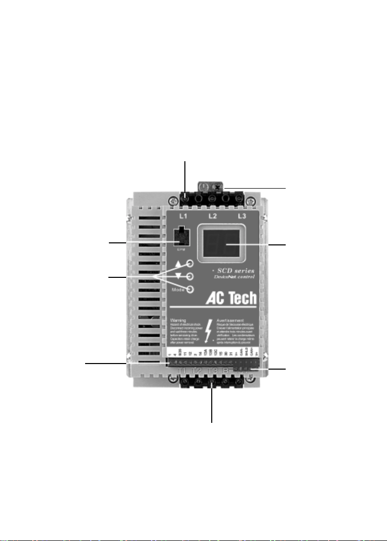
THE SCD SUB-MICRO DRIVE
INPUT POWER TERMINALS
GROUND LUG
ELECTRONIC
PROGRAMMING
MODULE (EPM)
PROGRAMMING
BUTTONS
CONTROL
TERMINAL
STRIP
OUTPUT (MOTOR) TERMINALS
3-DIGIT LED
DISPLAY
DEVICENET
TERMINAL
STRIP
(REMOVABLE)
TM
Page 4

1.0 GENERAL
1.1 PRODUCTS COVERED IN THIS MANUAL
This manual covers the AC Tech SCD Series Variable Frequency Drive.
1.2 PRODUCT CHANGES
AC Technology Corporation reserves the right to discontinue or make modifications to the design of
its products without prior notice, and holds no obligation to make modifications to products sold
previously. AC Technology Corporation also holds no liability for losses of any kind which may
result from this action.
1.3 WARRANTY
AC Technology Corporation warrants the SCD Series AC motor control to be free of defects in
material and workmanship for a period of twelve months from the date of sale to the user, or eighteen
months from the date of shipment, which ever occurs first. If an SCD motor control, under normal
use, becomes defective within the stated warranty time period, contact AC Technology's Service
Department for instructions on obtaining a warranty replacement unit. AC Technology Corporation
reserves the right to make the final determination as to the validity of a warranty claim, and sole
obligation is to repair or replace only components which have been rendered defective due to faulty
material or workmanship. No warranty claim will be accepted for components which have been
damaged due to mishandling, improper installation, unauthorized repair and/or alteration of the
product, operation in excess of design specifications or other misuse, or improper maintenance.
AC Technology Corporation makes no warranty that its products are compatible with any other
equipment, or to any specific application, to which they may be applied and shall not be held liable
for any other consequential damage or injury arising from the use of its products.
This warranty is in lieu of all other warranties, expressed or implied. No other person, firm or
corporation is authorized to assume, for AC Technology Corporation, any other liability in
connection with the demonstration or sale of its products.
1.4 RECEIVING
Inspect all cartons for damage which may have occurred during shipping. Carefully unpack equipment
and inspect thoroughly for damage or shortage. Report any damage to carrier and/or shortages to
supplier. All major components and connections should be examined for damage and tightness, with
special attention given to PC boards, plugs, knobs and switches.
1.5 CUSTOMER MODIFICATION
AC Technology Corporation, its sales representatives and distributors, welcome the opportunity to
assist our customers in applying our products. Many customizing options are available to aid in this
function. AC Technology Corporation cannot assume responsibility for any modifications not
authorized by its engineering department.
1
Page 5

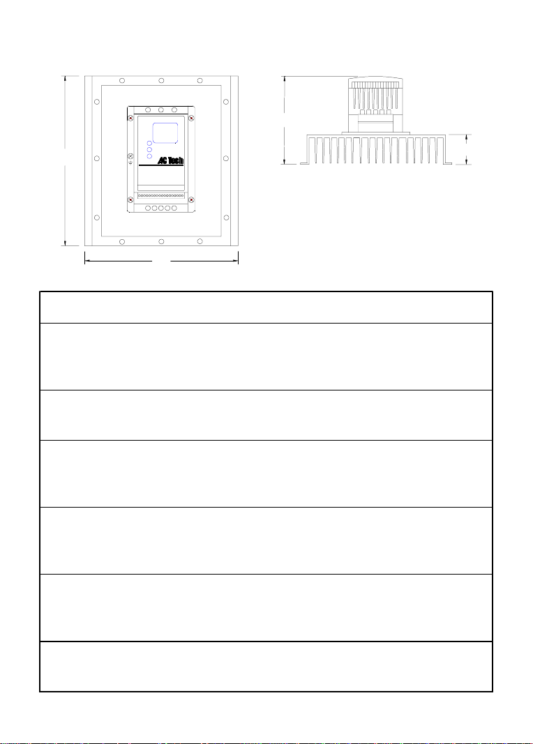
2.0 SCD DIMENSIONS
0.38" (9.5 mm)
H
W
D
R
T
U
P
S
Dia. Slot
Mounting Tab Detail
If R < 6.30" (160)
S = 0.19" (4.8)
T = 0.38" (9.5)
U = 0.18" (4.6)
V = 0.69" (18)
V
If R = 6.30" (160)
S = 0.28" (7.1)
T = 0.50" (13)
U = 0.24" (6.1)
V = 0.92" (23)
INPUT
HP kW VOLTAGE MODEL H W D P R
0.25 0.18 208 / 240 SD203Y 5.75 (146) 2.88 (73) 3.94 (100) 0.80 (20) 4. 37 (111)
0.5 0.37 208 / 240 SD205Y 5. 75 (146) 2.88 (73) 3.94 (100) 0.80 (20) 4. 37 (111)
400 / 480 SD405 5.75 (146) 2.88 (73) 3.94 (100) 0.80 (20) 4.37 (111)
1 0.75 208 / 240 SD210Y 5.75 (146) 2.88 (73) 4.74 (120) 1.60 (41) 4.37 (111)
208 / 240 SD210 5.75 (146) 2.88 (73) 4.74 (120) 1.60 (41) 4.37 (111)
400 / 480 SD410 5.75 (146) 2.88 (73) 4.74 (120) 1.60 (41) 4.37 (111)
480 / 590 SD510 5.75 (146) 2.88 (73) 4.74 (120) 1.60 (41) 4.37 (111)
1.5 1.1 208 / 240 SD215Y 5.75 (146) 3.76 (96) 5.24 (133) 1.90 (48) 4.37 (111)
208 / 240 SD215 5.75 (146) 2.88 (73) 5.74 (146) 2.60 (66) 4.37 (111)
400 / 480 SD415 5.75 (146) 2.88 (73) 5.74 (146) 2.60 (66) 4.37 (111)
2 1.5 208 / 240 SD220Y 5.75 (146) 3.76 (96) 6.74 (171) 3.40 (86) 4.37 (111)
208 / 240 SD220 5.75 (146) 2.88 (73) 5.74 (146) 2.60 (66) 4.37 (111)
400 / 480 SD420 5.75 (146) 2.88 (73) 5.74 (146) 2.60 (66) 4.37 (111)
480 / 590 SD520 5.75 (146) 2.88 (73) 5.74 (146) 2.60 (66) 4.37 (111)
2
Page 6

INPUT
HP kW VOLTAGE MODEL H W D P R
3 2.2 208 / 240 SD230Y 5.75 (146) 3.76 (96) 6.74 (171) 3.40 (86) 3. 25 (83)
208 / 240 SD230 5.75 (146) 2.88 (73) 5.74 (146) 2.60 (66) 3.06 (78)
400 / 480 SD430 5.75 (146) 2.88 (73) 5.74 (146) 2.60 (66) 3.06 (78)
480 / 590 SD530 5.75 (146) 3.76 (96) 6.74 (171) 3.40 (86) 4.37 (111)
5 3.7 208 / 240 SD250Y 7.75 (197) 5.02 (128) 7.18 (182) 3.40 (86) 4.81 (122)
208 / 240 SD250 5.75 (146) 3.76 (96) 6.74 (171) 3.40 (86) 3.25 (83)
400 / 480 SD450 5.75 (146) 3.76 (96) 6.74 (171) 3.40 (86) 3.25 (83)
480 / 590 SD550 5.75 (146) 3.76 (96) 6.74 (171) 3.40 (86) 3.25 (83)
7.5 5.5 208 / 240 SD 275 7.75 (197) 5.02 (128) 7.18 (182) 3.40 (86) 4.81 (122)
400 / 480 SD475 7.75 (197) 5.02 (128) 7.18 (182) 3.40 (86) 4.81 (122)
480 / 590 SD575 7.75 (197) 5.02 (128) 7.18 (182) 3.40 (86) 4.81 (122)
10 7.5 208 / 240 SD2100 7.75 (197) 5.02 (128) 7.18 (182) 3.40 (86) 4.81 (122)
400 / 480 SD4100 7. 75 (197) 5.02 (128) 7.18 (182) 3.40 (86) 4.81 (122)
480 / 590 SD5100 7. 75 (197) 5.02 (128) 7.18 (182) 3.40 (86) 4.81 (122)
15 11 208 / 240 SD2150 9. 75 (248) 6.68 (170) 8.00 (203) 3.60 (91) 6.30 (160)
400 / 480 SD4150 9. 75 (248) 6.68 (170) 8.00 (203) 3.60 (91) 6.30 (160)
480 / 590 SD5150 9. 75 (248) 6.68 (170) 8.00 (203) 3.60 (91) 6.30 (160)
20 15 208 / 240 SD2200 9. 75 (248) 6.68 (170) 8.00 (203) 3.60 (91) 6.30 (160)
400 / 480 SD4200 9. 75 (248) 6.68 (170) 8.00 (203) 3.60 (91) 6.30 (160)
480 / 590 SD5200 9. 75 (248) 6.68 (170) 8.00 (203) 3.60 (91) 6.30 (160)
25 18.5 400 / 480 SD4250 9.75 (248) 6.68 (170) 8.00 (203) 3.60 (91) 6.30 (160)
480 / 590 SD5250 9. 75 (248) 6.68 (170) 8.00 (203) 3.60 (91) 6.30 (160)
3
Page 7
2.1 SCD THROUGH-HOLE MOUNT DIMENSIONS
D
H
W
P
INPUT
HP kW VOLTAGE MODEL H W D P
1 0.75 208 / 240 SD 210YF 7.72 (196) 6.80 (173) 4.55 (116) 1.20 (30)
208 / 240 SD210F 7.72 (196) 6.80 (173) 4.55 (116) 1.20 (30)
400 / 480 SD410F 7.72 (196) 6.80 (173) 4.55 (116) 1.20 (30)
480 / 590 SD510F 7.72 (196) 6.80 (173) 4.55 (116) 1.20 (30)
1.5 1.1 208 / 240 SD 215YF 7.72 (196) 6.80 (173) 4.75 (121) 1.20 (30)
208 / 240 SD215F 7.72 (196) 6.80 (173) 4.55 (116) 1.20 (30)
400 / 480 SD415F 7.72 (196) 6.80 (173) 4.55 (116) 1.20 (30)
2 1.5 208 / 240 SD 220YF 7. 72 (196) 6.80 (173) 4.75 (121) 1.20 (30)
208 / 240 SD220F 7.72 (196) 6.80 (173) 4.55 (116) 1.20 (30)
400 / 480 SD420F 7.72 (196) 6.80 (173) 4.55 (116) 1.20 (30)
480 / 590 SD520F 7.72 (196) 6.80 (173) 4.55 (116) 1.20 (30)
3 2.2 208 / 240 SD 230YF 7. 72 (196) 8.54 (217) 5.30 (135) 1.75 (44)
208 / 240 SD230F 7.72 (196) 8.54 (217) 5.10 (130) 1.75 (44)
400 / 480 SD430F 7.72 (196) 8.54 (217) 5.10 (130) 1.75 (44)
480 / 590 SD530F 7.72 (196) 8.54 (217) 5.30 (135) 1.75 (44)
5 3.7 208 / 240 SD250YF 9.59 (244) 11.14 283) 7.65 (194) 3.60 (91)
208 / 240 SD250F 7.72 (196) 8.54 (217) 6.30 (160) 2.75 (70)
400 / 480 SD450F 7.72 (196) 8.54 (217) 6.30 (160) 2.75 (70)
480 / 590 SD550F 7.72 (196) 8.54 (217) 6.30 (160) 2.75 (70)
7.5 5.5 208 / 240 SD 275F 11. 59 (294) 11.14 (283) 7.65 (194) 3.60 (91)
400 / 480 SD 475F 9.59 (244) 11.14 (283) 7.65 (194) 3.60 (91)
480 / 590 SD 575F 9.59 (244) 11.14 (283) 7.65 (194) 3.60 (91)
4
Page 8

INPUT
HP kW VOLTAGE MODEL H W D P
10 7.5 208 / 240 SD2100F 15.59 (396) 11.14 (283) 7.65 (194) 3.60 (91)
400 / 480 SD4100F 11.59 (294) 11.14 (283) 7.65 (194) 3.60 (91)
480 / 590 SD5100F 11.59 (294) 11.14 (283) 7.65 (194) 3.60 (91)
15 11 208 / 240 SD 2150F 18.09 (459) 11. 14 (283) 8.29 (211) 3.60 (91)
400 / 480 SD4150F 15.59 (396) 11.14 (283) 8.29 (211) 3.60 (91)
480 / 590 SD5150F 15.59 (396) 11.14 (283) 8.29 (211) 3.60 (91)
20 15 400 / 480 SD 4200F 18.09 (459) 11. 14 (283) 8.29 (211) 3.60 (91)
480 / 590 SD5200F 18.09 (459) 11.14 (283) 8.29 (211) 3.60 (91)
25 18.5 400 / 480 SD4250F 28. 50 (724) 10.34 (263) 8.39 (213) 3.70 (94)
480 / 590 SD5250F 28.50 (724) 10.34 (263) 8.39 (213) 3.70 (94)
NOTE: Refer to Appendix A for mounting template dimensions for the Through-hole Mount option.
3.0 SCD MODEL DESIGNATION CODE
The SCD model number gives a full description of the basic drive unit (see example below).
EXAMPLE: SD210Y (SCD Series, 208/240 Vac, 1 HP, single or three phase input)
SD 2 10 Y
Series:
150
200
250
TM
= 15 Hp
= 20 Hp
= 25 Hp
SD = SCD Series Variable Speed AC Motor Drive with DeviceNet
Input Voltage:
2
= 208/240 Vac (For 208, 220, 230, and 240 Vac; 50 or 60 Hz)
4
= 400/480 Vac (For 380, 415, 440, 460 and 480 Vac; 50 or 60 Hz)
5
= 480/590 Vac (For 460, 480, 550, 575 and 600 Vac; 50 or 60 Hz)
Horsepower:
03
= ¼ Hp
05
= ½ Hp
10
= 1 Hp
Input: Phase:
Y = Single or three phase input
No character indicates three phase input only
Mounting Style:
FF1= Through-hole mount with special heatsink
= Through-hole mount without heatsink (customer supplies heatsink)
No character indicat es panel or DIN rail mounting
Application Specific Options:
V = High Frequency Output – up to 1000 Hz
15
20
30
= 1½ Hp
= 2 Hp
= 3 Hp
100
50
75
= 5 Hp
= 7½ Hp
= 10 Hp
5
Page 9

4.0 SCD SPECIFICATIONS
Storage Tem perature -20 to 70 C
Ambient Operat ing T em perature 0 to 50 C (up to 6 k H z c arrier, derate above 6 k Hz)
Ambient H um idit y < 95% (non-condensing)
Maxim um Alt it ude 3300 ft (1000 m) abov e s ea lev el (w it hout derat ing)
Input Line Voltages 208/240 Vac, 400/ 480 Vac, 480/590 Vac
Input Volt age Tolerance +10%, -15%
Input F requency T olerance 48 to 62 Hz
Output W av e Form Sine Coded PWM
Output F requency 0 - 240 Hz (cons ult f ac tory f or higher output f requencies)
Carrier Frequency 4 kHz t o 10 kH z
Service F act or 1.00 (up to 6 kH z c arrier, derat e above 6 kH z )
Effic ienc y Up to 98%
Power Fac t or (dis plac em ent) 0.96 or bett er
Overload Current C apacit y 150% for 60 seconds, 180% for 30 sec onds
Speed Referenc e F ollower 0-10 VDC , 4-20 m A
Cont r ol V oltage 15 VD C
Power Supply for Auxiliary Relay s 50 mA at 12 VDC
Analog Outputs 0 - 10 VDC or 2 - 10 VDC: Proportional to frequenc y or load
Digital Out puts Open-collect or outputs : 50 mA at 30 VDC
4.1 DEVICENETTM ELECTRICAL SPECIFICATIONS
Supply Voltage 11 t o 25 VDC
Current C ons um pt ion (max ) 50 mA @ 11 VD C
Baud Rates and M ax Distanc e 125 kbps - 500 m (1640 ft )
250 kbps - 250 m (820 ft )
500 kbps - 100 m (328 ft )
6
Page 10

5.0 SCD RATINGS
MODEL OUTPUT
NUMBER INPUT CURRENT POWER CURRENT
(NOT E 1) HP kW PHASE (AM PS ) (kVA) (AMPS)
SD200Y SER I ES (N OTE 2)
SD203Y 0.25 0.18 1 3.6 / 3.2 0.76 1.6 / 1.4 19 N/ A
SD203Y 0.25 0.18 3 1.9 / 1.7 0.71 1.6 / 1.4 19 N/ A
SD205Y 0.5 0.37 1 5.4 / 4.7 1.2 2.5 / 2.2 26 N/ A
SD205Y 0.5 0.37 3 3.1 / 2.7 1.1 2.5 / 2.2 26 N/ A
SD210Y 1 0.75 1 10.6 / 9. 2 2.2 4.8 / 4.2 49 18
SD210Y 1 0.75 3 5.8 / 5. 1 2.1 4.8 / 4. 2 49 18
SD215Y 1.5 1.1 1 13.9 / 12. 0 2.9 6.9 / 6. 0 82 23
SD215Y 1.5 1.1 3 8.0 / 6.9 2.9 6.9 / 6. 0 82 23
SD220Y 2 1.5 1 14.8 / 12.9 3.1 7.8 / 6. 8 86 26
SD220Y 2 1.5 3 9.1 / 7. 9 3.2 7.8 / 6. 8 86 26
SD230Y 3 2.2 1 19.7 / 17.1 4.1 11. 0 / 9. 6 130 29
SD230Y 3 2.2 3 12.4 / 10.8 4.4 11. 0 / 9. 6 130 29
SD250Y 5 3.7 1 29 / 26 6.1 17.5 / 15. 2 212 40
SD250Y 5 3.7 3 19.6 / 17.1 7.1 17.5 / 15. 2 212 40
SD200 SERIES (N OTE 2) 208 / 240 Vac
SD210 1 0.75 3 5.8 / 5. 1 2.1 4.8 / 4. 2 41 11
SD215 1. 5 1.1 3 8.0 / 6.9 2.9 6.9 / 6.0 69 13
SD220 2 1.5 3 9.1 / 7. 9 3.3 7.8 / 6.8 78 15
SD230 3 2.2 3 12. 4 / 10. 8 4.5 11. 0 / 9. 6 117 20
SD250 5 3.7 3 19. 6 / 17. 1 7.1 17.5 / 15. 2 187 22
SD275 7. 5 5.5 3 28 / 25 10. 3 25 / 22 286 31
SD2100 10 7.5 3 34 / 32 13.1 30 / 28 379 39
SD2150 15 11 3 54 / 48 20.0 48 / 42 476 51
SD2200 20 15 3 65 / 61 25.4 58 / 54 648 N/A
NOT E 1: See Sec t ion 3. 0 f or m odel number break dow n.
NOT E 2: T he higher c urrent rat ings are f or 208 Vac input and t he low er c urrent rat ings are f or 240 Vac input.
NOTE 5: STD = s tandard unit; T HR U = t hrough-hole mount unit. Values are wors t- cas e (not t y pical) for 6k Hz
carrier frequency at f ull speed and full load.
FOR MOTORS INPUT (50-60 Hz)
RATED
208 / 240 Vac
0 - 200 / 230 Vac STD THR U
0 - 200 / 230 Vac
HEAT LO SS
(WATTS)
(NOT E 5)
7
Page 11
MODEL OUTPUT
NUMBER INPUT CURRENT POWER CURRENT
FOR MOTORS INPUT (50-60 Hz)
RATED
(NOT E 1) HP kW PHAS E (AMPS) (kVA) (AMPS)
SD400 SERIE S (NOTE 3) 400 / 480 Vac
0 - 400 / 460 Vac STD THR U
HEAT LOSS
(WATTS)
(NOT E 5)
SD405 0. 5 0.37 3 1.6 / 1.4 1.1 1.3 / 1.1 26 N/ A
SD410 1 0.75 3 2.9 / 2. 5 2.1 2. 4 / 2. 1 40 12
SD415 1. 5 1.1 3 4.0 / 3.6 3.0 3.4 / 3.0 56 13
SD420 2 1.5 3 4.6 / 4.0 3.3 3.9 / 3. 4 67 14
SD430 3 2.2 3 6.2 / 5.4 4.5 5.5 / 4. 8 100 19
SD450 5 3.7 3 9.8 / 8.6 7.1 8.7 / 7. 6 168 22
SD475 7. 5 5.5 3 14. 2 / 12. 4 10.3 12.6 / 11. 0 254 29
SD4100 10 7.5 3 18. 1 / 15. 8 13.1 16.1 / 14. 0 310 37
SD4150 15 11 3 27 / 24 20.0 24 / 21 390 42
SD4200 20 15 3 35 / 31 25.8 31 / 27 530 57
SD4250 25 18.5 3 44 / 38 31.6 39 / 34 648 72
SD500 SERIE S (NOTE 4) 480 / 590 Vac
0 - 460 / 575 Vac
SD510 1 0.75 3 2.2 / 2. 0 1.9 / 2. 0 1.9 / 1. 7 40 12
SD520 2 1.5 3 4.0 / 3.5 3.3 / 3.6 3.4 / 3.0 67 13
SD530 3 2.2 3 4.7 / 4.7 3.9 / 4.8 4.2 / 4.2 100 14
SD550 5 3.7 3 7.4 / 7.4 6.1 / 7.5 6.6 / 6.6 168 19
SD575 7. 5 5.5 3 11. 2 / 11. 2 9. 3 / 11. 4 9.9 / 9. 9 254 29
SD5100 10 7.5 3 13. 7 / 13. 7 11.4 / 14.0 12.2 / 12. 2 310 37
SD5150 15 11 3 22 / 22 18.3 / 22. 5 19.0 / 19. 0 390 42
SD5200 20 15 3 27 / 27 22. 4 / 27.6 24 / 24 530 57
SD5250 25 18.5 3 31 / 31 25.8 / 31.7 27 / 27 648 72
NOT E 1: See Sec t ion 3.0 for model number breakdow n.
NOT E 3: T he higher c urrent rat ings are f or 400 Vac input and t he low er current rat ings are for 480 Vac input .
NOT E 4: T he higher c urrent rat ings are f or 480 Vac input and t he low er current rat ings are for 590 Vac input .
NOTE 5: ST D = s tandard unit; TH R U = through-hole mount unit . Values are w orst -c ase (not t y pical) for 6k H z
carrier frequency at f ull s peed and full load.
8
Page 12

6.0 INSTALLATION
SCD drives are intended for inclusion within other equipment, by professional electrical installers.
They are not intended for stand-alone operation.
DRIVES MUST NOT BE INSTALLED WHERE SUBJECTED TO ADVERSE ENVIRONMENTAL
CONDITIONS SUCH AS: COMBUSTIBLE, OILY, OR HAZARDOUS VAPORS OR DUST;
EXCESSIVE MOISTURE OR DIRT; VIBRATION; EXCESSIVE AMBIENT TEMPERATURES.
CONSULT AC TECHNOLOGY FOR MORE INFORMATION ON THE SUITABILITY OF A
DRIVE TO A PARTICULAR ENVIRONMENT.
SCD models are suitable for UL pollution degree 2 environment only, and MUST be installed in an
electrical enclosure which will provide complete mechanical protection and will maintain the internal
temperature within the drive’s ambient operating temperature rating. All drive models MUST be
mounted in a vertical position for proper heatsink cooling.
Maintain a minimum spacing around the drive of at least 1 inch on each side and 2 inches on the top
and bottom for units rated up to 5 HP (3.7 kW). For units rated 7.5 - 25 HP (5.5 - 18.5 kW), maintain
at least 2 inches on each side and 4 inches on the top and bottom. Allow more spacing if the drive is
mounted next to other heat-producing equipment. Do not mount drives above other drives or heat
producing equipment. Fans or blowers should be used to insure proper cooling in tight quarters.
In order to properly size an enclosure, the heat generated by the drive(s) must be known. Refer to the
HEAT LOSS columns in Section 5.0 - SCD RATINGS. The STD column is for standard units, and
the THRU column is for through-hole mount units (drives with the through-hole mount option still
generate some heat inside the enclosure that must be taken into account). An enclosure manufacturer
can then determine the required enclosure size based on the total heat generated inside the enclosure
(from the drive(s) and other heat sources), the maximum allowable temperature inside the enclosure,
the maximum ambient temperature outside the enclosure, and the enclosure properties.
NOTE!
WARNING!
The SCD Series is UL approved for solid state motor overload protection. Therefore, a separate
thermal overload relay is not required for single motor applications.
6.1 INSTALLATION AFTER A LONG PERIOD OF STORAGE
Severe damage to the drive can result if it is operated after a long period of storage or inactivity
without reforming the DC bus capacitors!
If input power has not been applied to the drive for a period of time exceeding three years (due to
storage, etc), the electrolytic DC bus capacitors within the drive can change internally, resulting in
excessive leakage current. This can result in premature failure of the capacitors if the drive is operated
after such a long period of inactivity or storage.
WARNING!
9
Page 13

In order to reform the capacitors and prepare the drive for operation after a long period of inactivity,
apply input power to the drive for 8 hours prior to actually operating the motor.
6.2 EXPLOSION PROOF APPLICATIONS
Explosion proof motors that are not rated for inverter use lose their certification when used for variable
speed. Due to the many areas of liability that may be encountered when dealing with these applications,
the following statement of policy applies:
“AC Technology Corporation inverter products are sold with no warranty of fitness for a
particular purpose or warranty of suitability for use with explosion proof motors. AC Technology
Corporation accepts no responsibility for any direct, incidental or consequential loss, cost, or
damage that may arise through the use of its AC inverter products in these applications. The
purchaser expressly agrees to assume all risk of any loss, cost, or damage that may arise from
such application."
7.0 INPUT AC POWER REQUIREMENTS
Hazard of electrical shock! Capacitors retain charge after power is removed. Disconnect incoming
power and wait until the voltage between terminals B+ and B- is 0 VDC before servicing the drive.
The input voltage must match the nameplate voltage rating of the drive. Voltage fluctuation must not
vary by greater than 10% overvoltage or 15% undervoltage.
NOTE: Drives with dual input voltage ratings must be programmed for the proper supply voltage
(refer to Parameter 01 - LINE VOLTAGE SELECTION in Section 15.0 - DESCRIPTION OF
PARAMETERS).
The drive is suitable for use on a circuit capable of delivering not more than 5,000 RMS symmetrical
amperes at 5 HP (3.7 kW) and below, and 18,000 RMS symmetrical amperes at 7.5 - 25 HP (5.5 -
18.5 kW), at the drive’s rated voltage.
If the kVA rating of the AC supply transformer is greater than 10 times the input kVA rating of the
drive(s), an isolation transformer or 2-3% input line reactor must be added to the line side of the
drive(s).
Three phase voltage imbalance must be less than 2.0% phase to phase. Excessive phase to phase
imbalance can cause severe damage to the drive’s power components.
Motor voltage should match line voltage in normal applications. The drive’s maximum output voltage
will equal the input voltage. Use extreme caution when using a motor with a voltage rating which is
different from the input line voltage.
WARNING!
10
Page 14

7.1 INPUT VOLTAGE RATINGS
SD200 Series drives are rated for 208/240 Vac, three phase, 50-60 Hz input. The drive will function
with input voltages of 208 to 240 Vac (+10%, -15%), at 48 to 62 Hz.
SD200Y Series drives are rated for 208/240 Vac, single or three phase, 50-60 Hz input. The drive
will function with input voltage of 208 to 240 Vac (+10%, -15%), at 48 to 62 Hz.
SD400 Series drives are rated for 400/480 Vac three phase, 50-60 Hz input. The drive will function
with input voltages of 400 to 480 Vac (+10%, -15%), at 48 to 62 Hz.
SD500 Series drives are rated for 480/590 Vac, three phase, 50-60 Hz input, and will function with
input voltages of 480 to 590 Vac (+10%, -15%), at 48 to 62 Hz.
NOTE: Parameter 01 - LINE VOLTAGE SELECTION must be programmed according to the applied
input voltage. See Section 15.0 - DESCRIPTION OF PARAMETERS.
7.2 INPUT FUSING AND DISCONNECT REQUIREMENTS
A circuit breaker or a disconnect switch with fuses must be provided in accordance with the National
Electric Code (NEC) and all local codes. Refer to the following tables for proper fuse/circuit breaker
ratings and wire sizes.
INPUT FUSE & CIRCUIT BREAKER RATINGS
400/480 Vac, 3 phas e208/240 Vac, 1 phas e 208/240 Vac, 3 phas e
MODEL RATING MODEL RATING MODEL RATING MODEL RATING
SD203Y 10 A SD203Y 10 A
SD205Y 10 A SD 205(Y) 10 A SD405 10 A
SD210Y 15 A SD 210(Y) 10 A SD410 10 A SD 510 10 A
SD215Y 20 A SD 215(Y) 12 / 10 A SD415 10 A
SD220Y 25 / 20 A SD220(Y) 15 / 12 A SD420 10 A SD520 10 A
SD230Y 30 / 25 A SD230(Y) 20 / 15 A SD430 10 A SD530 10 A
SD250Y 45 / 40 A SD250(Y) 30 / 25 A SD450 15 A SD550 12 A
SD275 45 / 40 A SD 475 20 A SD575 20 A
SD2100 50 / 50 A SD4100 30 / 25 A SD 5100 20 A
SD2150 80 / 75 A SD4150 40 / 40 A SD 5150 30 A
SD2200 100 / 90 A SD 4200 50 / 45 A SD5200 40 A
SD4250 70 / 60 A SD5250 45 A
480/590 Vac, 3 phas e
NOTE 1: Use UL Class CC fast-acting, current limiting type fuses. Select fuses with low I
values, rated at 200,000 AIC. Recommended fuses are Bussman KTK-R, JJN, and JJS. Similar fuses
with equivalent ratings by other manufacturers may also be acceptable.
11
2
T
Page 15

WIRE SIZE REQUIREMENTS
400/480 Vac, 3 phas e208/240 Vac, 1 phas e 208/240 Vac, 3 phase
MODEL AWG mm2MODEL AWG mm2MODEL AWG mm2MODEL AWG mm
SD203Y 14 2.5 SD203Y 14 2.5
SD205Y 14 2.5 SD205(Y) 14 2.5 SD405 14 2.5
SD210Y 14 2.5 SD210(Y) 14 2.5 SD410 14 2.5 SD510 14 2.5
SD215Y 14 2.5 SD215(Y) 14 2.5 SD415 14 2.5
SD220Y 14 2.5 SD220(Y) 14 2.5 SD420 14 2.5 SD520 14 2.5
SD230Y 12 4.0 SD230(Y) 14 2.5 SD430 14 2.5 SD530 14 2.5
SD250Y 10 6.0 SD250(Y) 12 4.0 SD450 14 2.5 SD550 14 2.5
SD275106.0SD475142 SD575 14 2.5.5
SD2100 8 10 SD4100 12 4.0 SD5100 14 2.5
SD2150 6 16 SD4150 10 6.0 SD5150 10 6.0
SD2200 4 25 SD4200 8 10 SD5200 10 6.0
SD4250 6 16 SD5250 8 10
480/590 Vac, 3 phas e
2
12
Page 16

8.0 POWER WIRING
Hazard of electrical shock! Capacitors retain charge after power is removed. Disconnect incoming
power and wait until the voltage between terminals B+ and B- is 0 VDC before servicing the drive.
Note drive input and output current ratings and check applicable electrical codes for required wire
type and size, grounding requirements, over-current protection, and incoming power disconnect,
before wiring the drive. Size conservatively to minimize voltage drop.
Strip off 0.20 to 0.25 inches (5 to 6 mm) of insulation for input power, output power, and DC Bus
wiring.
The input power, output power, and DC Bus terminals must be tightened to a torque of 4.5 lb-in (0.5
Nm).
Input fusing and a power disconnect switch or contactor MUST be wired in series with terminals L1,
L2, and L3 for three phase input models. For 208/240 Vac single phase input models, use terminals
L1 and L2. This disconnect must be used to power down the drive when servicing, or when the drive
is not to be operated for a long period of time, but should not be used to start and stop the motor.
Repetitive cycling of a disconnect or input contactor (more than once every two minutes) may
cause damage to the drive.
8.1 WIRING FOR SINGLE PHASE OR THREE PHASE INPUT
If the drive is rated for single and three phase input (SD200Y models), wire to terminals L1 and L2
for single phase input, or wire to terminals L1, L2, and L3 for three phase input.
If the drive is rated for three phase input, wire the input to terminals L1, L2, and L3.
All three power output wires, from terminals T1, T2, and T3 to the motor, must be kept tightly
bundled and run in a separate conduit away from all other power and control wiring.
WARNING!
It is not recommended to install contactors or disconnect switches between the drive and motor.
Operating such devices while the drive is running can potentially cause damage to the drive's power
components. If such a device is required, it should only be operated when the drive is in a STOP
state. If there is potential for the device to be opened while the drive is running, the drive must be
programmed for COAST to stop (see Parameter 4 - STOP METHOD), and an auxiliary contact on the
device must be interlocked with the drive's run circuit. This will give the drive a stop command at the
same time the device opens, and will not allow the drive to start again until the device is closed.
13
Page 17
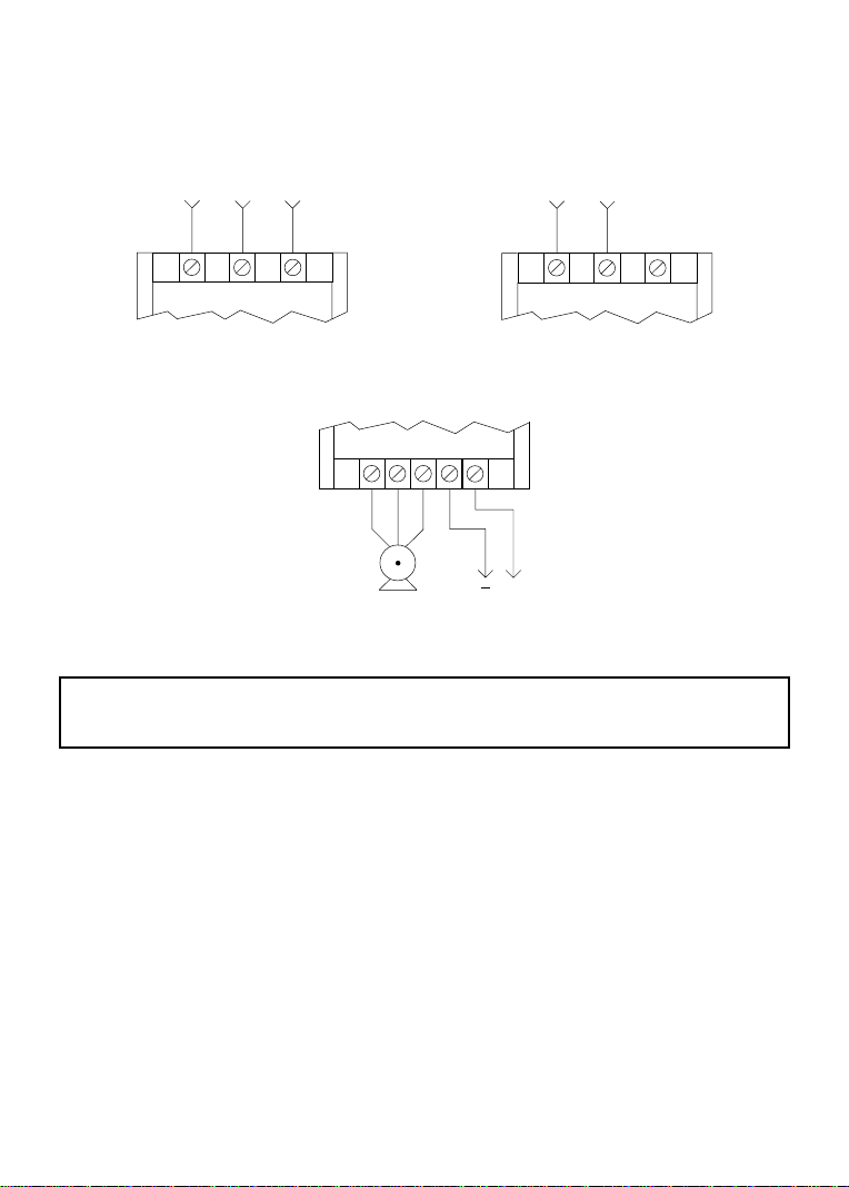
9.0 SCD POWER WIRING DIAGRAM
THREE PHASE INPUT
(SD200, SD200Y, SD400,
AND SD500 SERIES)
208/240 Vac SINGLE PHASE INPUT
(SD200Y SERIES)
L1 L2 L3
OUTPUT (ALL SERIES)
T1 T2 T3 B- B+
L1 L2 L3
+
3 PHASE
AC MOTOR
WARNING!
Do not connect incoming AC power to output terminals T1, T2, or T3. Severe damage to the drive
will result.
NOTES:
1. WIRE AND GROUND IN ACCORDANCE WITH NEC OR CEC, AND ALL APPLICABLE
LOCAL CODES.
2. Motor wires MUST be run in a separate steel conduit away from control wiring and incoming AC
power wiring.
3. Do not install contactors between the drive and the motor without consulting AC Technology for
more information. Failure to do so may result in drive damage.
4. Use only UL and CSA listed and approved wire.
5. Minimum wire voltage ratings: 300 V for 208 and 240 Vac systems, and 600 V for 400, 480, and
590 Vac systems.
6. Wire gauge must be based on a minimum of 125% of the rated input/output current of the drive,
and a minimum 75°C insulation rating. Use copper wire only.
7. Strip off 0.20 to 0.25 inches (5 to 6 mm) of insulation for input power, output power, and DC Bus
wiring.
DC BUS
VOLTAGE
14
Page 18

10.0 CONTROL WIRING
10.1 CONTROL WIRING VS. POWER WIRING
External control wiring MUST be run in a separate conduit away from all other input and output
power wiring. If control wiring is not kept separate from power wiring, electrical noise may be
generated on the control wiring that will cause erratic drive behavior. Use twisted wires or shielded
cable grounded at the drive chassis ONLY. Recommended control wire is Belden 8760 (2-wire) or
8770 (3-wire), or equivalent.
Strip off 0.20 to 0.25 inches (5 to 6 mm) of insulation for control wiring, and torque the control
terminals to 2 lb-in (0.2 Nm). Be careful not to overtorque the control terminals, as this will cause
damage to the terminal strip. This is not covered under warranty and can only be repaired by replacing
the control board.
10.2 TB-2 AND TB-4
The TB-2 terminal is the circuit common for the analog input and analog output functions. If necessary
TB-2 may be connected to chassis ground.
The TB-4 terminal is the reference for all of the digital inputs (TB-1, 12, 13A, 13B, 13C). On
standard SCD drives, TB-4 is at zero volt potential. Therefore, the digital inputs are active-low.
10.3 SURGE SUPPRESION ON RELAYS
Current and voltage surges and spikes in the coils of contactors, relays, solenoids, etc, near or connected
to the drive, can cause erratic drive operation. Therefore, a snubber circuit should be used on coils
associated with the drive. For AC coils, snubbers should consist of a resistor and a capacitor in series
across the coil. For DC coils, a free-wheeling or flyback diode should be placed across the coil.
Snubbers are typically available from the manufacturer of the device.
10.4 START/STOP CONTROL
There are various control schemes that allow for 2-wire and 3-wire Start/Stop circuits. Refer to the
wiring diagrams in Section 11.0 - SCD CONTROL WIRING DIAGRAMS
10.5 SPEED REFERENCE SIGNALS
The drive allows for three analog speed reference inputs:
SPEED POT Connect the wiper of a speed pot (rated 2.5kΩ up to 10kΩ) to terminal TB-5/25, and
0-10 VDC Wire the positive to terminal TB-5/25 and the negative to terminal TB-2. TB-5/25
4-20 mA Wire the positive to terminal TB-5/25 and the negative to terminal TB-2. TB-5/25
connect the high and low end leads to terminals TB-11 and TB-2, respectively.
input impedance is 120 kilohms when programmed for 0-10 VDC input.
input impedance is 100 ohms when programmed for 4-20 mA.
15
Page 19

NOTE: When the drive is powered down, the input impedance of terminal TB-5/25 becomes 57
kilohms. If TB-5/25 was programmed as a 4-20 mA input, the 4-20 mA source will suddenly encounter
a high input impedance.
10.6 SPEED REFERENCE SELECTION
If only one speed reference is required, set Parameter 05 - STANDARD SPEED SOURCE to the
desired speed reference. The selections are: KEYPAD (the ! and " buttons on the front of the
drive), PRESET SPEED #1 (Parameter 31), a 0-10 VDC signal, or a 4-20 mA signal.
If multiple speed references are required, terminals 13A, 13B, and 13C can be programmed to select
other speed references in addition to the STANDARD SPEED SOURCE (Parameter 05). When the
TB-13 terminal is closed to TB-4, the drive will follow the selected speed reference. If a speed
reference is not selected using TB-13A, 13B, or 13C, speed control will default back to the source
programmed in STANDARD SPEED SOURCE.
When using the DeviceNet interface, speed reference selection can be done as described above.
However, DeviceNet can override the selected speed reference and directly control the drive speed.
Refer to Appendix B - DEVICENET CONTROL for more information.
0 - 10 VDC and 4 - 20 mA INPUT SIGNALS
TB-13A, TB-13B, and TB-13C can all be programmed to select a 0-10 VDC or 4-20 mA analog
speed reference input.
PRESET SPEEDS
TB-13A can be programmed to select PRESET SPEED #1, TB-13B to select PRESET SPEED #2,
and TB-13C to select PRESET SPEED #3. There are a total of seven preset speeds, which are
activated by different combinations of contact closures between TB-13A, 13B, 13C and TB-4. Refer
to Parameters 31-37 in Section 15.0 - DESCRIPTION OF PARAMETERS.
JOG
TB-13B can be programmed to select either JOG FORWARD or JOG REVERSE. The Jog speed is
set by PRESET SPEED #2. Close TB-13B to TB-4 to JOG, and open the contact to STOP.
When operating in JOG mode, the STOP terminal (TB-1) and the STOP key (on the optional remote
keypad) WILL NOT stop the drive. To stop the drive, remove the JOG command.
JOG REVERSE will operate the drive in reverse rotation even if ROTATION DIRECTION (Parameter
17) is set to FORWARD ONLY.
NOTE: If the drive is commanded to JOG while running, the drive will enter JOG mode and run at
PRESET SPEED #2. When the JOG command is removed, the drive will STOP.
WARNING!
16
Page 20

MOTOR OPERATED POT (MOP) / FLOATING POINT CONTROL
TB-13B and TB-13C are used for this function, which controls the drive speed using contacts wired
to the terminal strip. Program TB-13B for DECREASE FREQ (05), and program TB-13C for
INCREASE FREQ (05). Closing TB-13B to TB-4 will cause the speed setpoint to decrease until the
contact is opened. Closing TB-13C to TB-4 will cause the speed setpoint to increase until the contact
is opened. The INCREASE FREQ function will only operate while the drive is running.
NOTE: If TB-13A, TB-13B, and TB-13C are all programmed to select speed references, and two or
three of the terminals are closed to TB-4, the higher terminal has priority and will override the others.
For example, if TB-13A is programmed to select 0-10VDC, and TB-13C is programmed to select
PRESET SPEED #3, closing both terminals to TB-4 will cause the drive to respond to PRESET
SPEED #3, because TB-13C overrides TB-13A.
The exception to this is the MOP function, which requires the use of TB-13B and TB-13C. This
leaves TB-13A to be used for some other function. If TB-13A is programmed for a speed reference,
and TB-13A is closed to TB-4, TB-13A will override the MOP function.
10.7 ANALOG OUTPUT SIGNALS
Terminal TB-30 can provide a 0-10 VDC or a 2-10 VDC signal proportional to output frequency or
load, and TB-31 can provide the same signals proportional to load only. The 2-10 VDC signal can be
converted to a 4-20 mA signal using a resistor in series with the signal such that the total load
resistance is 500 Ohms. Refer to Parameters 08 and 09 in Section 15.0 - DESCRIPTION OF
PARAMETERS.
NOTE: These analog output signals cannot be used with “loop-powered” devices that derive power
from a 4-20 mA signal.
10.8 DRIVE STATUS DIGITAL OUTPUTS
There are two open-collector outputs at terminals TB-14 and TB-15. The open-collector circuits are
current-sinking types rated at 30 VDC and 50 mA maximum.
The open-collector outputs can be programmed to indicate one of various drive status conditions.
Refer to Parameters 06 and 13 in Section 15.0 - DESCRIPTION OF PARAMETERS.
The diagram below illustrates how the 12 VDC power supply at TB-11 can be used with the opencollector output to drive an external relay:
DIODE SNUBBER
(1N4148 or Equivalent)
TB-11
RELAY COIL
STRIP
TB-14
SCD TERMINAL
17
Page 21

11.0 SCD CONTROL WIRING DIAGRAMS
11.1 SCD TERMINAL STRIP
Shown below is the terminal strip on the main control board, along with a brief description of the
function of each terminal.
1 4 5/25 11 2 CAN+V+14 13B 13C 1513A 3 0 V-
STOP
DIGITAL INPUT REFERENCE
12 31 SHLD
DEVICENETTM INTERFACE
START
ANALOG COMMON
TB-13C FUNCTION SELECT
TB-13B FUNCTION SELECT
TB-13A FUNCTION SELECT
12 VDC SUPPLY (50 mA MAX)
0-10 VDC or 4-20 mA SPEED REFERENCE INPUT
OPEN-COLLECTOR OUTPUT
OPEN-COLLECTOR OUTPUT
0-10 OR 2-10 VDC OUTPUT: LOAD
0-10 OR 2-10 VDC OUTPUT: FREQ. OR LOAD
CAN-
Removable Connector
(Refer to Appendix B)
NOTE: The function of terminals TB-13A, TB-13B, TB-13C, TB-14, TB-15, TB-30, and TB-31 are
dependent on the programming of certain parameters. Refer to Sections 14.0 - PARAMETER MENU
and 15.0 - DESCRIPTION OF PARAMETERS.
Additional information on operating the drive from the terminal strip can be found in Section 10.0 CONTROL WIRING. The following diagrams provide a quick reference to wire the drive for the
most common configurations.
18
Page 22
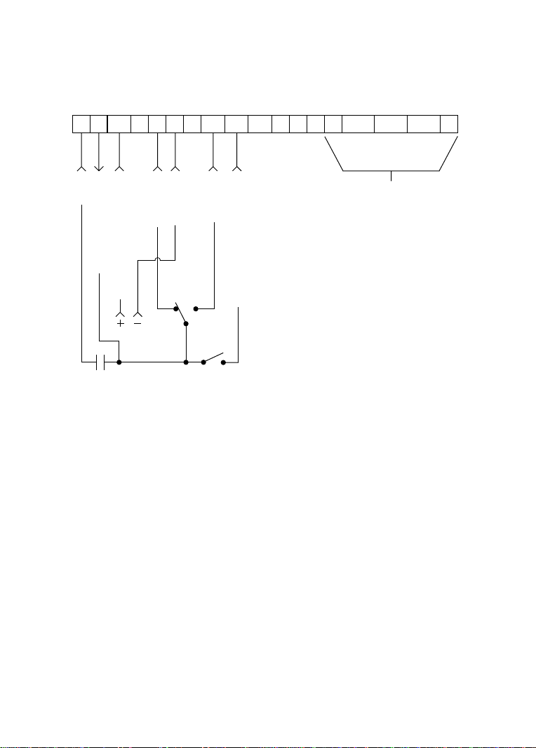
11.2 TWO-WIRE START/STOP CONTROL
Shown below is the wiring diagram for a typical two-wire start/stop control scheme, using one
maintained contact (such as that from a PLC) for RUN and STOP commands.
1 4 5/25 11 2 CAN+ V+14 13B 13C 1513A 30 V-12 31 SHLDCAN-
STOP
DIGITAL INPUT REF.
0-10 VDC or 4-20 mA INPUT
MAINTAINED
RUN/STOP
CONTACT
COMMON
FORWARD
FWD REV
REVERSE
0-10 VDC or 4-20 mA SELECT
DEVICENETTM INTERFACE
Removable Connector
(Refer to Appendix B)
NOTES:
1. Close TB-1 to TB-4 to RUN, and open TB-1 to TB-4 to STOP.
2. If reverse direction is also required, ROTATION DIRECTION (Parameter 17) must be set to
FORWARD AND REVERSE (02), and TB-13A (Parameter 10) must be set to START REVERSE
(06). If reverse direction is not required, TB-12 must be wired directly to TB-4.
3. For 0-10 VDC or 4-20 mA speed control, use one of the following methods:
1. Program one of the TB-13 terminals (13A, 13B, or 13C) for 0-10 VDC (02) or 4-20 mA (03).
When that TB-13 terminal is closed to TB-4, the drive will respond to the selected speed
reference signal. If that TB-13 terminal is not closed to TB-4, the drive will respond to the
speed control source selected in Parameter 05 - STANDARD SPEED SOURCE. This method
must be used if it is necessary to toggle between two speed sources.
2. Program Parameter 05 - STANDARD SPEED SOURCE for 0-10 VDC (03) or 4-20 mA (04).
This method is preferable if only one speed source is required, as this method leaves the TB13 terminals free to be used for other functions.
19
Page 23
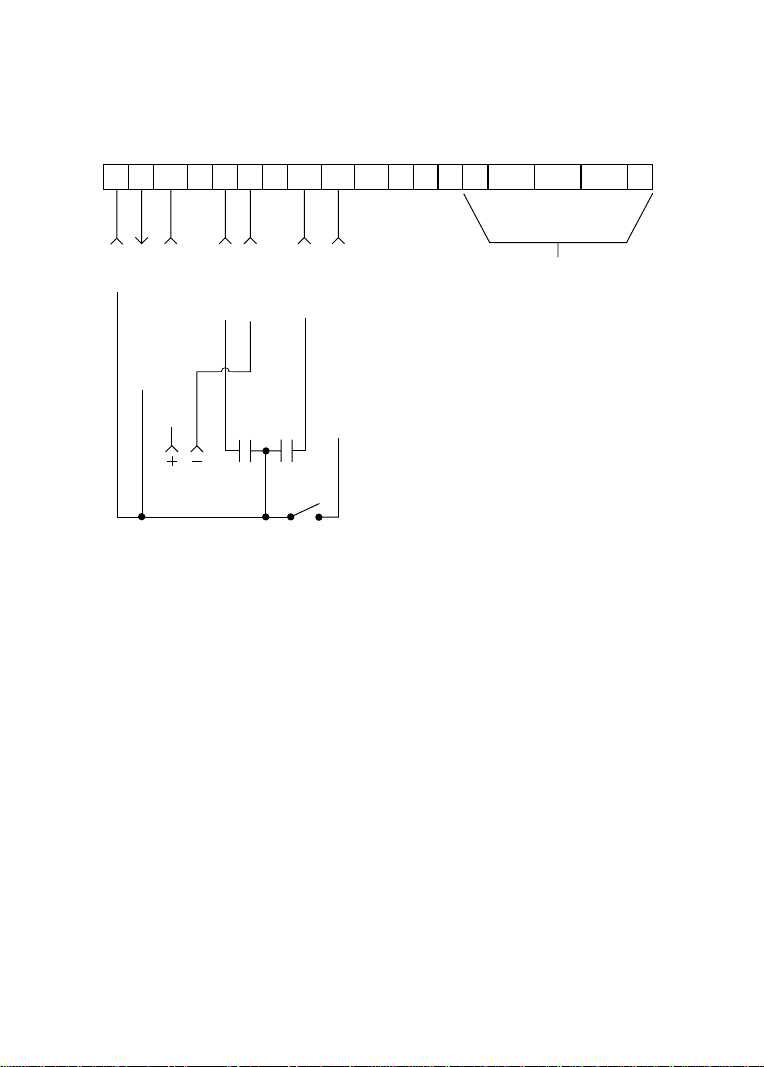
11.3 ALTERNATE TWO-WIRE START/STOP CONTROL
Shown below is the wiring diagram for an alternate two-wire start/stop control scheme, using one
maintained contact for RUN FORWARD and another maintained contact for RUN REVERSE.
1 4 5/25 11 2 CAN+V+14 13B 13C 1513A 3 0 V-12 31 SHLDCAN-
TM
STOP
DIGITAL INPUT REF.
RUN FWD
COMMON
RUN REV
DEVICENET
Removable Connector
(Refer to Appendix B)
INTERFACE
0-10 VDC or 4-20 mA INPUT
FWD REV
0-10 VDC or 4-20 mA SELECT
NOTES:
1. For this control scheme, TB-13A MUST be set to RUN REVERSE (05), even if REVERSE
direction is not required. Refer to Parameter 10 - TB13A FUNCTION.
2. Close TB-12 to TB-4 to RUN in forward direction, and open TB-12 to TB-4 to STOP.
3. If reverse direction is also required, ROTATION DIRECTION (Parameter 17) must be set to
FORWARD AND REVERSE (02). Close TB-13A to TB-4 to RUN in REVERSE, and open TB13A to TB-4 to STOP. If TB-12 and TB-13A are both closed to TB-4, the drive will STOP.
4. For 0-10 VDC or 4-20 mA speed control, use one of the following methods:
1. Program one of the TB-13 terminals (13A, 13B, or 13C) for 0-10 VDC (02) or 4-20 mA (03).
When that TB-13 terminal is closed to TB-4, the drive will respond to the selected speed
reference signal. If that TB-13 terminal is not closed to TB-4, the drive will respond to the
speed control source selected in Parameter 05 - STANDARD SPEED SOURCE. This method
must be used if it is necessary to toggle between two speed reference sources.
2. Program Parameter 05 - STANDARD SPEED SOURCE for 0-10 VDC (03) or 4-20 mA (04).
This method is preferable if only one speed reference source is required, as this method
leaves the TB-13 terminals free to be used for other functions.
20
Page 24
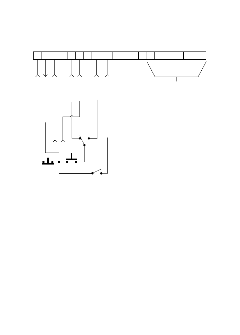
11.4 THREE-WIRE START/STOP CONTROL
Shown below is the wiring diagram for a typical three-wire start/stop control scheme, using momentary
contacts (such as pushbuttons) for START and STOP commands.
1 4 5/25 11 2 CAN+ V+14 13B 13C 1513A 30 V-12 31 SHLDCAN-
STOP
DIGITAL INPUT REF.
0-10 VDC or 4-20 mA INPUT
FWD REV
STOP START
COMMON
FORWARD
REVERSE
0-10 VDC or 4-20 mA SELECT
DEVICENETTM INTERFACE
Removable Connector
(Refer to Appendix B)
NOTES:
1. Momentarily close TB-12 to TB-4 to START the drive in forward direction, and momentarily
open TB-1 to TB-4 to STOP the drive.
2. If reverse direction is also required, ROTATION DIRECTION (Parameter 17) must be set to
FORWARD AND REVERSE (02), and TB-13A (Parameter 10) must be set to START REVERSE
(06). If the FWD/REV switch is changed while the drive is running, the drive will not change
direction until the START button is pushed. If reverse direction is not required, the other side of
the START pushbutton must be wired directly to TB-12.
3. For 0-10 VDC or 4-20 mA speed control, use one of the following methods:
1. Program one of the TB-13 terminals (13A, 13B, or 13C) for 0-10 VDC (02) or 4-20 mA (03).
When that TB-13 terminal is closed to TB-4, the drive will respond to the selected speed
reference signal. If that TB-13 terminal is not closed to TB-4, the drive will respond to the
speed control source selected in Parameter 05 - STANDARD SPEED SOURCE. This method
must be used if it is necessary to toggle between two speed sources.
2. Program Parameter 05 - STANDARD SPEED SOURCE for 0-10 VDC (03) or 4-20 mA (04).
This method is preferable if only one speed source is required, as this method leaves the TB13 terminals free to be used for other functions.
21
Page 25

11.5 SPEED POT AND PRESET SPEED CONTROL
Shown below is the wiring for SPEED POT and/or PRESET SPEED control, and either a two-wire or
three-wire start/stop circuit:
1 4 5/25 11 2 CAN+ V+14 13B 13C 1513A 30 V-12 31 SHLDCAN-
STOP
0-10 VDC INPUT
DIGITAL INPUT REF.
12 VDC POWER SUPPLY
STOP
START
START
COMMON
PRESET SPEED SELECT
PRESET SPEED SELECT
PRESET SPEED SELECT
DEVICENETTM INTERFACE
Removable Connector
(Refer to Appendix B)
NOTES:
1. Program the PRESET SPEEDS (Parameters 31-37) to the desired values.
2. Program TB-13A (Parameter 10) to PRESET SPEED #1 (04), TB-13B (Parameter 11) to PRESET
SPEED #2 (04), and TB-13C (Parameter 12) to PRESET SPEED #3 (04). To select a preset
speed, close the appropriate TB-13 terminal(s) to TB-2 (refer to Parameters 31-37 for the Preset
Speed Activation table).
3. If reverse rotation is also required, TB-13A cannot be used as a PRESET SPEED SELECT. TB13A must be programmed to select RUN REVERSE (05) or START REVERSE (06), leaving
only TB-13B and TB-13C to select preset speeds.
4. For speed pot control, program Parameter 05 - STANDARD SPEED SOURCE for 0-10 VDC
(03). If none of the preset speeds are selected (all of the TB-13 terminals are open), the drive will
respond to the speed pot.
22
Page 26

12.0 INITIAL POWER UP AND MOTOR ROTATION
DO NOT connect incoming AC power to output terminals T1, T2, and T3! Severe damage to the
drive will result. Do not continuously cycle input power to the drive more than once every two
minutes. Damage to the drive will result.
Hazard of electrical shock! Wait three minutes after disconnecting incoming power before servicing
drive. Capacitors retain charge after power is removed.
Severe damage to the drive can result if it is operated after a long period of storage or inactivity
without reforming the DC bus capacitors!
If input power has not been applied to the drive for a period of time exceeding three years (due to
storage, etc), the electrolytic DC bus capacitors within the drive can change internally, resulting in
excessive leakage current. This can result in premature failure of the capacitors if the drive is operated
after such a long period of inactivity or storage.
In order to reform the capacitors and prepare the drive for operation after a long period of inactivity,
apply input power to the drive for 8 hours prior to actually operating the motor.
Before attempting to operate the drive, motor, and driven equipment, be sure all procedures pertaining
to installation and wiring have been properly followed.
Disconnect the driven load from the motor. Verify that the drive input terminals (L1, L2, and L3) are
wired to the proper input voltage per the nameplate rating of the drive.
WARNING!
WARNING!
WARNING!
Energize the incoming power line. The LED display will flash a three digit number (322 in the
example below) that identifies the parameter version contained in the drive. The display should then
read “- - -”, which indicates that the drive is in a STOP condition. This is shown below:
Apply input power
Display flashes parameter
version (300-399)
Display then reads "- - -"
23
Page 27

Follow the procedure below to check the motor rotation. This procedure assumes that the drive
has been powered up for the first time, and that none of the parameters have been changed.
1. Use the ! button to decrease the speed setpoint to 00.0 Hz. The left decimal point will illuminate
as the speed setpoint is decreased. If the ! button is held down, the speed setpoint will decrease
by tenths of Hz until the next whole Hz is reached, and then it will decrease by one Hz increments.
Otherwise, each push of the ! button will decrease the speed setpoint by a tenth of a Hz.
Once 00.0 Hz is reached, the display will toggle between “00.0” and “- - -”, which indicates that
the drive is in a STOP condition with a speed setpoint of 00.0 Hz.
2. Give the drive a START command. This can be done using one of several wiring methods
described in Section 11.0 - SCD CONTROL WIRING DIAGRAMS. Once the START command
is issued, the display will read “00.0”, indicating that the drive is in a RUN condition with a
speed setpoint of 00.0 Hz.
3. Use the " button to increase the speed setpoint until the motor starts to rotate. The left decimal
point will light as the speed setpoint is increased. If the " button is held down, the speed
setpoint will increase by tenths of Hz until the next whole Hz is reached, and then it will increase
by one Hz increments. Otherwise, each push of the button will increase the speed setpoint by a
tenth of a Hz.
4. If the motor is rotating in the wrong direction, give the drive a STOP command and remove
power from the drive. Wait three minutes for the bus capacitors to discharge, and swap any two
of the motor wires connected to T1, T2, and T3.
NOTE: The drive is phase insensitive with respect to incoming line voltage. This means that the
drive will operate with any phase sequence of the incoming three phase voltage. Therefore, to change
the motor rotation, the phases must be swapped at the drive output terminals or at the motor.
24
Page 28

13.0 PROGRAMMING THE SCD DRIVE
The drive may be programmed by one of three methods: using the three buttons and 3-digit LED
display on the front of the drive, programming the Electronic Programming Module (EPM) using the
optional EPM Programmer, and through the DeviceNet interface (refer to Appendix B). This section
describes programming the drive using the buttons and display, which are shown below:
BUTTONS
Mode
To enter the PROGRAM mode to access the parameters, press the Mode button. This will activate
the PASSWORD prompt (if the password has not been disabled). The display will read “00” and the
upper right-hand decimal point will be blinking, as shown below:
Press Mode
Display reads "00"
Upper right decimal point blinks
Use the " and ! buttons to scroll to the password value (the factory default password is “225”) and
press the Mode button. Once the correct password value is entered, the display will read "P01",
which indicates that the PROGRAM mode has been accessed at the beginning of the parameter menu
(P01 is the first parameter). This is shown below:
Use " and ! to scroll to the
password value
Press Mode to enter password
DISPLAY
Parameter menu is accessed at the
first parameter
25
Page 29

NOTE: If the display flashes “Er”, the password was incorrect, and the process to enter the password
must be repeated.
Use the " and ! buttons to scroll to the desired parameter number. In the example below, Parameter
19 is being displayed, which is the ACCELERATION TIME of the drive:
Use " and ! to scroll to the desired
parameter number (the example is
Parameter 19 - ACCELERATION
TIME)
Once the desired parameter number is found, press the Mode button to display the present parameter
setting. The upper right-hand decimal point will begin blinking, indicating that the present parameter
setting is being displayed, and that it can be changed by using the " and ! buttons.
Press Mode to display present
parameter setting (example setting
is 20.0)
Upper right decimal point blinks
Use " and ! to change setting
(example setting changed to 30.0)
Press Mode to store new setting
Pressing the Mode will store the new setting and also exit the PROGRAM mode. To change another
parameter, press the Mode key again to re-enter the PROGRAM mode (the parameter menu will be
accessed at the parameter that was last viewed or changed before exiting). If the Mode key is pressed
within two minutes of exiting the PROGRAM mode, the password is not required access the parameters.
After two minutes, the password must be entered in order to access the parameters again.
26
Page 30

13.1 SETTING VALUES IN TENTHS OF UNITS ABOVE 100
Parameter settings and the keypad speed command can always be adjusted in tenths of unit increments
from 0.0 to 99.9. Above 100 however, values can be set in whole units or tenths of units, depending
on the setting of Parameter 16 - UNITS EDITING.
If Parameter 16 - UNITS EDITING is set to WHOLE UNITS (02), parameter values and the keypad
speed command can only be adjusted by whole unit increments above 100. For example, Parameter
19 - ACCELERATION TIME could not be set to 243.7 seconds. It could only be set to 243 or 244
seconds. Likewise, the keypad speed command (set using the " and ! buttons) could not be set to
113.4 Hz. It could only be set to 113 or 114 Hz.
If, however, Parameter 16 - UNITS EDITING is set to TENTHS OF UNITS (01), parameter values
and the keypad speed command can be adjusted in tenths of unit increments up to a value of 1000
(above 1000, whole unit increments only). Each push of the " or ! button will adjust the value by
one tenth of a unit. If the " or ! button is pressed and held, the value will increment by tenths of
units until the next whole unit is reached, and then the value will increment by whole units.
When a value above 100 is being adjusted by tenths of units, the value is shifted to the left by one
digit so that the tenths portion of the value can be displayed. This results in the first digit (reading
from left to right) of the value disappearing from the display. Also, the lower decimal point will
blink to indicate that the actual value is above 100. Once the value is no longer being adjusted, the
value will shift back to the right and the tenths portion of the value will disappear.
In the example below, Parameter 19 - ACCELERATION TIME is presently set to 243.0 seconds, and
is being increased to 243.7 seconds.
Go to Parameter 19 and press Mode
to see present setting ("243" seconds)
Upper right decimal point blinks
Press " button to see tenths portion
Value shifts to the left ("2" disappears)
Upper right decimal point and lower
decimal point blink
Press " button to scroll up to "43.7"
Press Mode to store new value
27
Page 31

13.2 ELECTRONIC PROGRAMMING MODULE (EPM)
Every SC Series drive has an Electronic Programming Module (EPM) installed on the main control
board. The EPM stores the user’s parameter settings and special OEM default settings (if programmed).
The EPM is removable, allowing it to be installed in another drive for quick set-up. For example, if
a drive is being replaced with a new one, the EPM can be taken out of the first drive and installed in
the new drive. Downtime is minimized because the new drive does not require programming - it is
ready to run when the EPM is installed.
The SC Series drive contains two or three sets of parameter values, depending on whether the drive
has been programmed with optional OEM default settings. The first set of values is the factory
default settings, which are permanently stored on the main control board and cannot be changed. The
second set of values is the user settings, which are stored in the EPM. When the drive leaves the
factory, the user settings are the same as the factory default settings, but the user settings can be
changed to configure the drive for a particular application. The optional third set of values is the
OEM default settings, which are also stored in the EPM. OEM default settings are typically used in
cases where many drives are used for the same application, which requires that all of the drives have
the same parameter settings. The OEM default settings cannot be changed without the optional EPM
Programmer. The drive can be programmed to operate according to the user settings or the OEM
default settings (see Parameter 48 in Section 15.0).
NOTE: The drive will not operate without the EPM installed. The drive will display “F1” if the
EPM is missing or damaged.
Do not remove the EPM while power is applied to the drive. Damage to the EPM and/or drive may
result.
An EPM Programmer is available as an option from AC Tech, which has the ability to quickly and
easily program many SC Series drives for the same configuration. Once a “master” EPM is programmed
with the desired parameter settings, the EPM Programmer can copy those settings to other EPMs,
allowing many drives to be configured very quickly. Please consult the EPM Programmer Instruction
Manual or contact the factory for more information.
If the OEM settings in the EPM become corrupted, the drive will operate normally, until an attempt
is made to perform a RESET OEM using Parameter 48 - PROGRAM SELECTION. The drive will
then flash “GF” to indicate that the OEM settings are no longer valid. This will require that the EPM
be re-programmed using the optional EPM Programmer.
If the OEM settings and the user settings are both corrupted, the drive will display “GF” immediately
and the drive will require a RESET 60 or RESET 50 using Parameter 48 - PROGRAM SELECTION.
Once the RESET is performed, the parameters can then be programmed individually to match the
OEM default settings. This will allow the drive to operate as if it were in OEM mode, even though it
is actually operating in USER mode. Refer to Parameter 48 in Section 15.0 - DESCRIPTION OF
PARAMETERS.
NOTE: The drive will also display “GF” if a RESET OEM or OPERATE WITH OEM SETTINGS
is attempted when the drive is not equipped with the OEM default option.
WARNING!
28
Page 32

14.0 PARAMETER MENU
FACTORY
NO. PARAMETER NAME RANGE OF ADJUSTMENT
01 LINE VOLTAGE HI GH (01), LOW (02) H I GH (01)
02 CARR I ER F R EQU EN C Y 4kHz (01), 6 k Hz (02), 8 k H z (03), 10 k H z (04) 6 kHz (02)
03 START M ETHOD NOR M AL (01), ST AR T ON POW ER UP (02), NORM AL (01)
START W IT H D C BRAKE (03),
AUT O R EST AR T W I T H D C BR AKE (04 ),
FLYIN G REST AR T 1 (05), F LYIN G R ESTAR T 2 (06),
FLYING RESTART 3 (07)
04 STOP METH OD COAST (01), C OAST W I T H DC BRAKE (02), COAST (01)
RAMP (03), R AM P W IT H DC BRAKE (04)
05 ST AN D AR D SPEE D KEYPAD (01), PR ESET #1 (02), KEYPAD (01)
SOURC E 0-10 VDC (03), 4-20 m A (04)
06 TB-14 OUTPU T NONE ( 01), R U N (02), FAU LT (03), NON E (01)
13 TB-15 OUTPUT INVERSE FAULT (04), FAULT LOCKOUT (05), NONE (01)
AT SET SPE ED (06), ABOVE PR ES ET #3 (07),
CURRENT LI M I T (08), AU TO SPEED (09),
REVERSE (10)
08 TB-30 OUTPU T NONE ( 01), 0-10 VD C F R EQ (02), NON E (01)
2-10 VD C F R EQ (03) , 0-10 VD C LO AD (04),
2-10 VDC LOAD (05)
09 TB-31 OUTPU T NONE (01), 0-10 VD C LOAD (02), NON E (01)
2-10 VDC LOAD (03), D YNA MI C BR AKI N G (04)
10 TB-13A FUN C T I ON NONE (01), 0-10 VDC (02), 4-20 mA (03), NON E (01)
SELECT PRESET SPEED #1 (04), RUN REVERSE (05),
STAR T R EVE RS E (06), EXT ER N AL FA UL T (07),
Fac tory Res erv ed (08), DB FAU LT (09),
AUXILI AR Y ST OP (10), AC C EL/ D EC EL #2 (11)
11 TB-13B FUN C T I ON NONE (01), 0-10 VDC (02), 4-20 mA (03), NON E (01)
SELEC T PRESET SPEED #2 (0 4), DE CREASE FR EQ (0 5),
JOG FORWARD (06), JOG REVERSE (07),
AUXILI AR Y ST OP (08)
DEFAULT
(NOT E 1)
NOTE 1: Factory defaults are shown for a 60 Hz base frequency. See Parameter 48 for 50 Hz base frequency .
29
Page 33

PARAMETER M ENU (CONT’D)
FACTORY
NO. PARAMETER NAME RANGE OF ADUSTMENT DEFAULT
(NOT E 1)
12 TB-13C FU N C T I ON NONE (01), 0-10 VDC (02), 4-20 m A (03), NON E (01)
SELEC T PRESET SP EED #3 (04), I N C R EASE F R EQ (05),
EXTERNAL FAULT (06), Factory Reserved (07),
DB FAU LT (08), ACC EL/ D ECEL #2 (09)
13 TB-15 OUTPUT (SEE PARAMETER 6 - TB-14 OUTPUT) NONE (01)
14 CONTROL TERMINAL STRIP & DEVICENET (01), TERMINAL STRIP &
DEVIC EN ET ON LY (02), DEVICEN ET (01)
16 UNIT S ED I T I N G T EN T H S OF U N I T S (01), WH OLE
WH OLE UN IT S (02) U N I TS (02)
17 ROTATI ON FOR WAR D ONLY (01), F ORW AR D
FORWARD AND REVERSE (02) ONLY (01)
19 ACC ELERAT I ON T I M E 0.1 - 3600.0 SEC 20.0 SEC
20 DEC ELERAT I ON T I M E 0.1 - 3600.0 SEC 20.0 SEC
21 DC BRAKE T I ME 0.0 - 3600.0 SEC 0.0 SEC
22 DC BR AK E VOLT AGE 0.0 - 30.0 % 0.0 %
23 MINIMUM FREQUENCY 0.0 - MAXIMUM FREQUENCY 0.0 Hz
24 MAXIM U M F R EQUEN C Y MI NI M U M F R EQ - 240.0 Hz (N OTE 2) 60.0 Hz
25 CURR EN T LI M I T 30 - 180 % (N OT E 3) 180%
26 MOTOR OVERLOAD 30 - 100 % 100%
27 BASE FREQU ENCY 25.0 - 500.0 Hz (N OT E 4) 60.0 Hz
28 FIXED BOOST 0.0 - 30.0 % 1.00%
29 ACCEL BOOST 0.0 - 20.0 % 0.00%
30 SLI P COM PENSAT I ON 0.0 - 5.0 % 0.00%
31-37 PRESET SPEEDS 0.0 - MAXIM U M F R EQUEN C Y 0.0 Hz
38 SKIP BAND W ID T H 0. 0 - 10.0 H z 0. 0 Hz
39 SPEED SC ALI NG 0.0 - 6500.0 0
NOTE 1: Factory defaults are shown for a 60 Hz base frequency. See Parameter 48 for 50 Hz base frequency .
NOTE 2: Maximum setting is 999.9 Hz on drives with High Output Frequency option. Consult the factory.
NOTE 3: If LINE VOLTAGE is set to LOW, maximum setting is 150%.
NOTE 4: Maximum setting is 1300.0 Hz (factory default is 999.9) on drives with High Output Frequency option.
Consult the factory .
30
Page 34

PA RAMETER MENU (CONT’D)
FACTORY
NO. PARAMETER NAME RANGE OF ADJUSTMENT
40 FREQU ENC Y SC ALI N G 3.0 - 2000.0 H z 60.0 Hz
41 LOAD SCALI N G 10 - 200 % 200 %
42 ACCEL / D EC EL #2 0.1 - 3600.0 SEC 20.0 SEC
44 PASSWORD 000 - 999 225
47 CLEAR HISTORY MAINTAIN (01), CLEAR (02) MAINTAIN (01)
48 PROGR AM USER SET T I N GS (01), OEM SETTI N GS (02), USER
SELECTI ON RESET OEM (03), R ESET 60 (04), SETT I N GS (01)
RESET 50 (05), T R AN SLATE (06)
50 FAU LT H IST OR Y (VIEW-ON LY) (N/A)
51 SOFTWARE CODE (VIEW-ONLY) (N/A)
52 DC BU S VOLT AG E (VIEW-ON L Y) (N /A )
53 MOTO R VOLT AG E (VIEW-ON LY) (N/A)
54 LOAD (VIEW-ONLY) (N/A)
55 0-10 VD C I N PU T (VIEW-ONLY) (N/ A)
56 4-20 mA INPU T (VIEW-ONLY) (N /A)
57 TB STRIP ST ATU S (VI EW-ON LY) (N/ A)
58 KEYPAD STATU S (VIEW-ONLY) (N/ A)
59 TB-30 OUTPU T (VIEW -ON LY) (N/ A)
60 TB-31 OUTPU T (VIEW -ON LY) (N/ A)
85 MOTO R R AT ED R PM 1 - 65000 R PM 1800 RPM
86 MOTOR RAT ED AMPS 0.0 - 999.9 AMPS 100.0 AMPS
87 MOTOR RAT ED VOLTS 0 - 1000 VOLTS 100 VOLTS
88 MOTO R R ATED F R EQ 0 - 1000 Hz 60 Hz
89 DRIVE RATED AM PS 0.0 - 999.9 AM PS 100.0 AMPS
90 DR I VE R ATED VOLT S 0 - 1000 VOLTS 100 VOLTS
DEFAULT
(NOT E 1)
NOTE 1: Factory defaults are shown for a 60 Hz base frequency. See Parameter 48 for 50 Hz base frequency .
31
Page 35

PA RAMETER MENU (CONT’D)
FACTORY
NO. PARAMETER NAME RANGE OF ADJUSTMENT
C00 DNET NODE ADDRESS 0 - 63 63
C01 DNET BAUD R AT E 125 k bps (0), 250 kbps (1), 500 kbps (2) 125 kbps (0)
C02 D N ET LOSS AC T I ON FAULT & ST OP (0), I GN OR E (1), AC T EC H (2) FAULT & ST OP (0)
C03 D N ET OU TPU T ASSY 1 BASIC CON TAC T OR (1), 20 BASIC SPEED
2 BASIC OVER LOAD (2), CONT R OL (6)
3 BASIC M OT OR ST ART ER (3),
4 EXTENDED CONTACTOR (4),
5 EXTE N D ED MOT O R START ER (5),
20 BASIC SPEED C ONT ROL (6),
21 EXTENDED SPEED CONTROL (7),
100 EXTENDED SPEED CONTROL Hz (8)
C04 DNET I N PU T ASSY 50 BASIC OVER LOAD (1), 70 BASIC SPEED
51 EXTENDED OV ER LOAD (2) CONTROL (6)
52 BASIC MOTOR CONTROL (3),
53 EXTENDED MOTOR CONTROL 1 (4),
54 EXTENDED MOTOR CONTROL 2 (5),
70 BASIC SPEED C ONT ROL (6),
71 EXTENDED SPEED CONTROL (7),
101 EXTENDED SPEED CONTROL Hz (8),
102 CUST OM ASSEMBLY (9)
C05 DNET CUSTOM ASSY 0 0 - 150 0
C06 DNET CUSTOM ASSY 1 0 - 150 0
C07 DNET CUSTOM ASSY 2 0 - 150 0
C08 DNET CUSTOM ASSY 3 0 - 150 0
C09 DNET MOTOR TYPE NON-STANDARD MOTOR (0), PM DC MOTOR (1), SQUIRREL CAGE
FC DC MOTOR (2), PM SYNCH. MOTOR (3), INDUCTION (7)
FC SYNCH. MOTOR (4), SWITCHED RELUCT. (5),
WOUND ROTOR INDUCTION (6),
SQUIRREL CAGE INDUCT ION (7),
STEPPER MOT OR (8), SIN USOI DAL PM BL (9),
TRAPEZ OID AL PM BL (10)
C10 DNET DIAGNOSTICS (READ ONLY) (N/A)
DEFAULT
(NOT E 1)
32
Page 36

15.0 DESCRIPTION OF PARAMETERS
P01 LINE VOLTAGE SELECTION
This calibrates the drive for the actual applied input voltage, and can be set to HIGH (01) or LOW
(02). Refer to the table below for the proper setting depending on the input voltage.
RATED INPUT INPUT APPLIED INPUT PARAMETER
MODEL VOLTAGE PHASE VOLTAGE SETTING
SF200Y 208 / 240 Vac 1 or 3 220 - 240 Vac HI GH (01)
1 or 3 200 - 208 Vac LOW (02)
SF200 208 / 240 Vac 3 220 - 240 Vac HI GH (01)
3 200 - 208 Vac LOW (02)
SF400 400 / 480 Vac 3 440 - 480 Vac HI GH (01)
3 380 - 415 Vac LOW (02)
SF500 480 / 590 Vac 3 575 - 600 Vac HI GH (01)
3 460 - 480 Vac LOW (02)
NOTE: If this parameter is changed while the drive is running, the new value will not take effect
until the drive is stopped.
P02 CARRIER FREQUENCY
This sets the switching rate of the output IGBT’s. Increasing the carrier frequency will result in less
audible motor noise. Available settings are: 4 kHz, 6 kHz, 8 kHz, and 10 kHz.
PARAMETER CARRIER MAXIMUM OUTPUT AMBIENT OR OUTPUT
SETTING FREQUENCY FREQUENCY (NOTE 1) DERATE (NOTE 2)
01 4 kH z 240.0 H z (400.0 Hz ) 50 C or 100%
02 6 kH z 240.0 H z (600.0 Hz ) 50 C or 100%
03 8 kH z 240.0 H z (999.9 Hz ) 43 C or 92%
04 10 kHz 240.0 Hz (999. 9 Hz ) 35 C or 82%
NOTE 1: For drives with the High Output Frequency option, the carrier frequency also determines
the maximum output frequency (shown in parenthesis).
NOTE 2: The SCD drive is fully rated up to 6 kHz carrier frequency. If the 8 kHz or 10 kHz carrier
frequency is selected, the drive’s ambient temperature rating OR output current rating must be derated to the value shown in the table above.
33
Page 37

NOTE 3: If this parameter is changed while the drive is running, the change will not take effect until
the drive is stopped. Therefore, the allowable maximum frequency for drives with the High Output
Frequency option (see NOTE 1) will not change if the carrier frequency is changed while the drive is
running.
P03 START METHOD
Automatic starting of equipment may cause damage to equipment and/or injury to personnel!
Automatic start should only be used on equipment that is inaccessible to personnel.
01 NORMAL: The drive will start when the appropriate contact is closed on the terminal strip, or
by pressing the START key on the optional remote keypad. See Parameter 14.
02 START ON POWER UP: The drive will automatically start upon application of input power.
03 START WITH DC BRAKE: When a START command is given, the drive will apply DC
BRAKE VOLTAGE (Parameter 22) for the duration of DC BRAKE TIME (Parameter 21) prior
to starting the motor to ensure that the motor is not turning.
04 AUTO RESTART WITH DC BRAKING: Upon a START command, after a fault, or upon
application of power, the drive will apply DC BRAKE VOLTAGE (Parameter 22) for the duration
of DC BRAKE TIME (Parameter 21) prior to starting (or restarting) the motor.
05 FLYING RESTART 1: LOW performance. Slowest synchronization and lowest current level.
This setting results in the smoothest synchronization.
06 FLYING RESTART 2: MEDIUM performance. Faster synchronization and higher current
level. This setting allows faster synchronization while retaining smoothness.
07 FLYING RESTART 3: HIGH performance. Fastest synchronization and highest current level.
This setting allows the fastest synchronization, but sacrifices smoothness.
The FLYING RESTART 1 - 3 settings allow the drive to start into a spinning load after a fault or
upon application of input power. They differ in the time required to find the motor and the amount of
current required to synchronize with it. The faster the drive attempts to find the motor, the more
current is required.
WARNING!
When programmed for auto-restart, the drive will attempt three restarts after a fault. The interval
between restart attempts is 15 seconds for setting 04, and 2 seconds for settings 05, 06 and 07.
During the interval between restart attempts, the display will read “SP” to indicate Start Pending. If
all three restart attempts fail, the drive will trip into FAULT LOCKOUT (displayed “LC”) and require
a manual reset. Refer to Section 16.0 - TROUBLESHOOTING.
NOTE: Settings 02 and 04 - 07 require a two-wire start/stop circuit to operate. The RUN contact
must remain closed for the power-up start and auto-restart functions to operate.
34
Page 38

P04 STOP METHOD
01 COAST TO STOP: When a STOP command is given, the drive shuts off the output to the
motor, allowing it to coast freely to a stop.
02 COAST WITH DC BRAKE: When a stop command is given, the drive will activate DC braking
(after a delay of up to 2 seconds, depending on frequency) to help decelerate the load. Refer to
Parameters: 21 - DC BRAKE TIME, and 22 - DC BRAKE VOLTAGE.
03 RAMP TO STOP: When a stop command is given, the drive will decelerate the motor to a stop
at the rate determined by Parameter 20 - DECELERATION TIME.
04 RAMP WITH DC BRAKE: When a stop command is given, the drive will decelerate the motor
down to 0.2 Hz (at the rate set by Parameter 20 - DECELERATION TIME) and then activate
DC braking according to the settings of Parameters 21 - DC BRAKE TIME and 22 - DC BRAKE
VOLTAGE. This is used to bring the load to a final stop, as the motor may still be turning
slightly after the drive stops.
P05 STANDARD SPEED SOURCE
This selects the speed reference source when the drive is in STANDARD speed mode. The following
speed references can be selected:
01 KEYPAD: Use the ! and " buttons to scroll to the desired speed.
02 PRESET SPEED #1: The drive will operate at the frequency set into Parameter 31.
03 0 - 10 VDC: The drive will respond to a 0-10 VDC signal wired to TB-2 and TB-5/25.
04 4 - 20 mA: The drive will respond to a 4-20 mA signal wired to TB-2 and TB-5/25.
P06 TB-14 OPEN COLLECTOR OUTPUT
This selects the status indication for the open-collector output at TB-14. The terms “open” and
“close” refer to the state of the internal transistor that activates the circuit. When the transistor is
“closed”, TB-14 is at the same potential as TB-2, allowing current to flow.
01 NONE: Disables the open-collector output.
02 RUN: Closes upon a START command. Opens if the drive is in a STOP state, the drive faults,
or input power is removed. DC braking is considered a STOP state.
03 FAULT: Closes if there is no fault condition. Opens if the drive faults, or input power is
removed.
04 INVERSE FAULT: Closes if the drive faults. Opens if there is no fault condition.
05 FAULT LOCKOUT: Closes when input power is applied. Opens if three restart attempts are
unsuccessful, or if input power is removed.
35
Page 39

06 AT SET SPEED: Closes if the drive is within + 0.5 Hz of the speed setpoint.
07 ABOVE PRESET SPEED #3: Closes if the output frequency exceeds the PRESET SPEED #3
setting. Opens if the output frequency is equal to or less than PRESET SPEED #3 (Parameter
33).
08 CURRENT LIMIT: Closes if the output current exceeds the CURRENT LIMIT setting. Opens
if the output current is equal to or less than CURRENT LIMIT (see Parameter 25).
09 AUTOMATIC SPEED MODE: Closes if an AUTOMATIC (terminal strip) speed reference is
active. Opens if a STANDARD (Parameter 5) speed reference is active.
10 REVERSE: Closes when reverse rotation is active. Opens when forward rotation is active. (see
Parameter 17 - ROTATION DIRECTION).
P08 TB-30 ANALOG OUTPUT
Terminal TB-30 can be used as an analog output proportional to either output frequency or load.
FREQUENCY SCALING (Parameter 40) or LOAD SCALING (Parameter 41) can be used to scale
the output signal.
01 NONE
02 0-10 VDC FREQ
03 2-10 VDC FREQ
04 0-10 VDC LOAD
05 2-10 VDC LOAD
NOTE: The 2-10 VDC signal can be converted to a 4-20 mA signal by connecting a resistor in series
with the signal such that the total load resistance is 500 Ohms. However, this output cannot be used
with devices that derive power from a 4-20 mA signal.
P09 TB-31 ANALOG OUTPUT
Terminal TB-31 can be used as an analog output proportional to load, or as the control signal to
activate the optional external Dynamic Braking module. LOAD SCALING (Parameter 41) can be
used to scale the output signal when TB-31 is used as an analog output proportional to load.
01 NONE
02 0-10 VDC LOAD
03 2-10 VDC LOAD
04 DYNAMIC BRAKING: TB-31 becomes the “trigger” that activates the optional
external Dynamic Braking module. Refer to the instructions included with the Dynamic
Braking option.
NOTE: The 2-10 VDC signal can be converted to a 4-20 mA signal by connecting a resistor in series
with the signal such that the total load resistance is 500 Ohms. However, this output cannot be used
with devices that derive power from a 4-20 mA signal.
36
Page 40

P10 TB-13A FUNCTION SELECT
This selects the function of terminal TB-13A. Closing TB-13A to TB-4 (or opening in the case of
settings 7 and 10) activates the selected function. The following functions can be selected:
01 NONE: Disables the TB-13A function.
02 0-10 VDC: Selects a 0-10 VDC signal (at TB-5/25) as the AUTO speed reference input.
03 4-20 mA: Selects a 4-20 mA signal (at TB-5/25) as the AUTO speed reference input.
04 PRESET SPEED #1: Selects PRESET SPEED #1 as the AUTO speed reference. The drive will
operate at the frequency programmed into Parameter 31.
05 RUN REVERSE: Close TB-13A to TB-4 to RUN in the reverse direction, and open to STOP.
This setting forces TB-12 to act as RUN FWD, requiring a maintained contact to RUN in the
forward direction. TB-1 must be closed to TB-4 for this function to operate.
06 START REVERSE: Momentarily close TB-13A to TB-4 to START the drive in the reverse
direction. Momentarily open TB-1 to TB-4 to STOP. This setting forces TB-12 to act as
START FWD, requiring a momentary contact to START in the forward direction.
07 EXTERNAL FAULT: Sets TB-13A as a normally closed external fault input. If TB-13A is
open with respect to TB-4, the drive will fault.
08 Factory Reserved: Equivalent to NONE (01).
09 DB FAULT: Sets TB-13A as a dynamic braking fault input when using the optional dynamic
braking module. When this input is activated by the dynamic braking module, the drive will
trip into a "dF" fault and the motor will coast to a stop. Refer to the manual included with the
Dynamic Braking option.
10 AUXILIARY STOP: When TB-13A is opened with respect to TB-4, the drive will decelerate
to a STOP (even if STOP METHOD is set to COAST) at the rate set into Parameter 42 - ACCEL/
DECEL #2.
11 ACCEL/DECEL #2: Selects the acceleration and deceleration time programmed into Parameter
42 - ACCEL/DECEL #2.
NOTE: In order for the RUN REVERSE and START REVERSE functions to operate, Parameter 17
- ROTATION DIRECTION must be set to FORWARD AND REVERSE (02).
P11 TB-13B FUNCTION SELECT
This selects the function of terminal TB-13B. Closing TB-13B to TB-4 (or opening in the case of
setting 08) activates the selected function. The following functions can be selected:
01 NONE: Disables the TB-13B function.
37
Page 41

02 0-10 VDC: Selects a 0-10 VDC signal (at TB-5/25) as the AUTO speed reference input.
03 4-20 mA: Selects a 4-20 mA signal (at TB-5/25) as the AUTO speed reference input.
04 PRESET SPEED #2: Selects PRESET SPEED #2 as the AUTO speed reference. The drive will
operate at the frequency programmed into Parameter 32.
05 DECREASE FREQUENCY: Decreases the speed setpoint when using the MOP function. Refer
to Section 10.6.
06 JOG FORWARD: Jog in the forward direction. In this mode, the drive will JOG at the speed
programmed into Parameter 32 - PRESET SPEED #2.
07 JOG REVERSE: Jog in the reverse direction. In this mode, the drive will JOG at the speed
programmed into Parameter 32 - PRESET SPEED #2.
When operating in JOG mode, the STOP terminal (TB-1), the AUXILIARY STOP function (see
setting 08), and the STOP key on the optional remote keypad WILL NOT stop the drive. To stop the
drive, remove the JOG command.
JOG REVERSE will operate the drive in reverse rotation even if ROTATION DIRECTION (Parameter
17) is set to FORWARD ONLY.
08 AUXILIARY STOP: When TB-13B is opened with respect to TB-4, the drive will decelerate to
a STOP (even if STOP METHOD is set to COAST) at the rate set into Parameter 42 - ACCEL/
DECEL #2.
NOTE: If the drive is commanded to JOG while running, the drive will enter JOG mode and run at
PRESET SPEED #2. When the JOG command is removed, the drive will STOP.
P12 TB-13C FUNCTION SELECT
This selects the function of terminal TB-13C. Closing TB-13C to TB-4 (or opening in the case of
setting 06) activates the selected function. The following functions can be selected:
01 NONE: Disables the TB-13C function.
02 0-10 VDC: Selects a 0-10 VDC signal (at TB-5/25) as the AUTO speed reference input.
03 4-20 mA: Selects a 4-20 mA signal (at TB-5/25) as the AUTO speed reference input.
04 PRESET SPEED #3: Selects PRESET SPEED #3 as the AUTO speed reference. The drive will
operate at the frequency programmed into Parameter 33.
05 INCREASE FREQUENCY: Increases the speed setpoint when using the MOP function. Refer
to Section 10.6.
WARNING!
38
Page 42

06 EXTERNAL FAULT: Sets TB-13C as a normally closed external fault input. If TB-13C is
open with respect to TB-4, the drive will fault.
07 Factory Reserved: Equivalent to NONE (01).
08 DB FAULT: Sets TB-13C as a dynamic braking fault input when using the optional dynamic
braking module. When this input is activated by the dynamic braking module, the drive will
trip into a "dF" fault and the motor will coast to a stop. Refer to the manual included with the
Dynamic Braking option.
09 ACCEL/DECEL #2: Selects the acceleration and deceleration time programmed into Parameter
42 - ACCEL/DECEL #2.
P13 TB-15 OPEN COLLECTOR OUTPUT
This selects the status indication for the open-collector output at TB-15, and has the same selections
as Parameter 6 - TB-14 OPEN COLLECTOR OUTPUT.
P14 CONTROL
This selects the source of START/STOP and direction commands.
01 TERMINAL STRIP & DEVICENET: The drive can be controlled from the terminal strip, or
can be controlled using DeviceNet serial communications.
02 DEVICENET ONLY: The drive can only be controlled using DeviceNet serial communications.
P16 UNITS EDITING
This allows parameter and keypad speed editing in whole units or tenths of units above 100. Below
100, the value can always be changed by tenths of units.
01 TENTHS OF UNITS: The value can always be changed by tenths of units (up to a value of
1000). If the ! or " button is pressed and held, the value will change by tenths of units until
the next whole unit is reached, and then the value will change by whole units. Refer to Section
13.1.
02 WHOLE UNITS: The value can be changed by tenths of units until 99.9 is reached. Above
99.9, the value will change in whole unit increments only. Below a value of 100, if the ! or "
button is pressed and held, the value will change by tenths of units until the next whole unit is
reached, and then the value will change by whole units.
P17 ROTATION DIRECTION
01 FORWARD ONLY: The drive will only allow rotation in the forward direction. However,
JOG REVERSE (see Parameter 11) will still operate even if FORWARD ONLY is selected.
02 FORWARD AND REVERSE: The drive will allow rotation in both directions.
39
Page 43

P19 ACCELERATION TIME
This parameter sets the acceleration rate for all of the speed reference sources (keypad, speed pot, 420 mA, 0-10 VDC, jog, MOP, and preset speeds). This setting is the time to accelerate from 0 Hz to
the BASE FREQUENCY (Parameter 27).
P20 DECELERATION TIME
This parameter sets the deceleration rate for all of the speed reference sources (keypad, speed pot, 420 mA, 0-10 VDC, jog, MOP, and preset speeds). This setting is the time to decelerate from BASE
FREQUENCY to 0 Hz. If the drive is set for COAST TO STOP (setting 01 or 02 in Parameter 04),
this parameter will have no effect when a STOP command is given.
P21 DC BRAKE TIME
This determines the length of time that the DC braking voltage is applied to the motor. The DC
BRAKE TIME should be set to the lowest value that provides satisfactory operation in order to
minimize motor heating.
P22 DC BRAKE VOLTAGE
This sets the magnitude of the DC braking voltage, in percentage of the nominal DC Bus voltage (DC
Bus = input AC voltage X 1.414). The point at which the DC braking is activated depends on the
selected STOP METHOD (Parameter 04):
If COAST WITH DC BRAKE is selected, the DC braking is activated after a time delay of up to 2
seconds, depending on the output frequency at the time of the STOP command. In this case, the DC
braking is the only force acting to decelerate the load.
If RAMP WITH DC BRAKE is selected, braking is activated when the output frequency reaches 0.2
Hz. In this case, the drive decelerates the load to a near stop and the DC braking is used to bring the
load to a final stop.
P23 MINIMUM FREQUENCY
This sets the minimum output frequency of the drive for all speed reference sources except the PRESET
SPEEDS (Parameters 31-37).
When using a 0-10 VDC or 4-20 mA analog speed reference signal, this parameter also sets the drive
speed that corresponds to the minimum analog input (0 VDC or 4 mA).
NOTE: If this parameter is changed while the drive is running, the new value will not take effect
until the drive is stopped.
P24 MAXIMUM FREQUENCY
This sets the maximum output frequency of the drive for all speed reference sources, and is used with
MINIMUM FREQUENCY (Parameter 23) to define the operating range of the drive.
40
Page 44

When using a 0-10 VDC or 4-20 mA analog speed reference signal, this parameter also sets the drive
speed that corresponds to the maximum analog input (10 VDC or 20 mA).
NOTE 1: On drives equipped with the High Output Frequency option, this parameter can be set up
to 999.9 Hz.
NOTE 2: If this parameter is changed while the drive is running, the new value will not take effect
until the drive is stopped.
P25 CURRENT LIMIT
This sets the maximum allowable output current of the drive. The maximum setting is either 180% or
150%, depending on whether LINE VOLTAGE SELECTION (Parameter 01) is set to HIGH or LOW.
The drive will enter current limit when the load demands more current than the CURRENT LIMIT
setting. When this happens, the drive will reduce the output frequency in an attempt to reduce the
output current. When the overload condition passes, the drive will accelerate the motor back up to
the speed setpoint.
P26 MOTOR OVERLOAD
The SCD Series is UL approved for solid state motor overload protection, and therefore does not
require a separate thermal overload relay for single motor applications.
The drive contains an adjustable thermal overload circuit that protects the motor from excessive
overcurrent. This circuit allows the drive to deliver up to 150% current for one minute. If the
overload circuit “times out”, the drive will trip into an OVERLOAD fault (displayed as "PF").
MOTOR OVERLOAD should be set to the ratio (in percent) of the motor current rating to the drive
current rating in order to properly protect the motor. See the example below.
Example: A 3 HP, 480 Vac drive with a 4.8 Amp rating is operating a 2 HP motor with a current
rating of 3.4 Amps. Dividing the motor current rating by the drive current rating yields 71% (3.4 /
4.8 = 0.71 = 71%), so this parameter should be set to 71%.
P27 BASE FREQUENCY
The BASE FREQUENCY determines the V/Hz ratio by setting the output frequency at which the
drive will output full voltage to the motor. In most cases, the BASE FREQUENCY should be set to
match the motor’s rated frequency.
Example: A 460 Vac, 60 Hz motor requires a V/Hz ratio of 7.67 (460 V / 60 Hz = 7.67 V/Hz) to
produce full torque. Setting the BASE FREQUENCY to 60 Hz causes the drive to output full voltage
(460 Vac) at 60 Hz, which yields the required 7.67 V/Hz. Output voltage is proportional to output
frequency, so the 7.67 V/Hz ratio is maintained from 0 - 60 Hz, allowing the motor to produce full
torque from 2 Hz (below 2 Hz there is less torque due to slip) up to 60 Hz.
41
Page 45

NOTE: If this parameter is changed while the drive is running, the new value will not take effect
until the drive is stopped.
P28 FIXED BOOST
FIXED BOOST increases starting torque by increasing the output voltage when operating below half
of the base frequency, which increases the V/Hz ratio (see diagram below). For better out-of-the-box
performance, SCD Series drives are shipped with a setting that is different from the factory default, as
seen in the table below. If a factory reset is performed, FIXED BOOST will default to 1.0 %.
FACTORY FACTORY
HP SETTING HP SETTING
0.25 - 1 5.3 % 7.5 2.7 %
1.5 4.4 % 10 2.4 %
2 4.4 % 15 2.2 %
Full
Output
Volts
V/Hz Ratio
Affected By
Fixed Boost
"Normal"
Linear V/Hz
Ratio
3 3.6 % 20 2.0 %
5 3.0 % 25 1.8 %
1/2 Base
Frequency
Base
Frequency
P29 ACCELERATION BOOST
ACCELERATION BOOST helps accelerate high-inertia loads. During acceleration, the output voltage
is increased to increase motor torque. Once the motor reaches the new speed setpoint, the boost is
turned off and the output voltage returns to the normal value.
P30 SLIP COMPENSATION
SLIP COMPENSATION is used to counteract changes in motor speed (slip) caused by changes in
load. In a standard AC induction motor, the shaft speed decreases as load increases, and increases as
load decreases. By increasing or decreasing the output frequency in response to an increasing or
decreasing load, the slip is counteracted and speed is maintained. Most standard NEMA B motors
have a 3% slip rating.
P31-P37 PRESET SPEED #1 - #7
Preset speeds are activated by contact closures between TB-4 and TB-13A, 13B, and 13C. The TB13 terminals must be programmed as preset speed selects using Parameters 10-12.
NOTE 1: Preset speeds can operate below the frequency defined by the minimum frequency parameter
(Parameter 23). The range of adjustment for the preset speeds is from 0 Hz to the maximum frequency
(Parameter 24).
Refer to the table below for activation of the preset speeds using the TB-13 terminals.
42
Page 46

SPEED # TB - 13A TB - 13B TB - 13C
1 CLOSED OPEN OPEN
2 OPEN CLOSED OPEN
3 OPEN OPEN CLOSED
4 CLOSED CLOSED OPEN
5 CLOSED OPEN CLOSED
6 OPEN CLOSED CLOSED
7 CLOSED CLOSED CLOSED
NOTE 2: When a TB-13 terminal is programmed for a function other than a preset speed select, it is
considered OPEN for the table above.
Preset Speed #6 and #7 can also be used as skip frequencies to restrict the drive from operating at
frequencies that cause vibration in the system. See Parameter 38 below.
P38 SKIP BANDWIDTH
The SCD drive has two skip frequencies that can be used to lock out critical frequencies that cause
mechanical resonance in the system. Once SKIP BANDWIDTH is set to a value other than 0.0 Hz,
the skip frequencies are enabled. When the skip frequency function is enabled, PRESET SPEED #6
and #7 are used as the skip frequencies. SKIP BANDWIDTH sets the range above the skip frequencies
that the drive will not operate within.
Example: The critical frequency is 23 Hz, and it is desired to skip a frequency range of 3 Hz above
and below the critical frequency (therefore the skip range is 20 to 26 Hz). PRESET SPEED #6 or #7
would be set to 20 Hz, and the SKIP BANDWIDTH would be set to 6.0 Hz.
If the drive is running at a speed below the skip range, and it is given a speed command that is within
the skip range, the drive will accelerate to the start of the skip range (20 Hz in the example) and run
at that speed until the speed command is greater than or equal to the "top" of the skip range. The
drive will then accelerate through the skip range to the new speed. Likewise, if the drive is running
at a speed above the skip range, and it is given a speed command that is within the skip range, the
drive will decelerate to the "top" of the skip range (26 Hz in the example) and run at that speed until
the speed command is less than or equal to the "bottom" of the skip range. The drive will then
decelerate through the skip range to the new speed.
NOTE: PRESET SPEEDS #6 and #7 can still be used as preset speeds even if they are also being
used as skip frequencies.
P39 SPEED SCALING
This scales the display to indicate speed or user units other than frequency. This parameter should be
set to the desired display value when the drive output is 60 Hz. The highest setting is 6500, and the
highest value that can be displayed is 6553.6.
43
Page 47

Example: A machine produces 175 parts per hour when the motor is running at 60 Hz. Setting the
SPEED SCALING to 175 will calibrate the drive's display to read 175 when the motor is running at
60 Hz. This is a linear function, so at 30 Hz the display would read 87.5, and at 120 Hz, the display
would read 350.
NOTE: If SPEED SCALING is set such that the maximum displayable value (6553.6) is exceeded,
the display will flash "9999" to indicate that the value is out of range. For example, if SPEED
SCALING is set to 6000, the drive will display 6000 when it is running at 60 Hz. If the speed is
increased past 65.5 Hz (at 65.5 Hz, the scaled value would be 6550), the display will flash "9999"
because a scaled value above 6553.6 cannot be displayed.
P40 FREQUENCY SCALING
This scales the analog output signal at TB-30 when it is configured for a frequency output. This
setting is the output frequency that is indicated when the output signal measures 10 VDC.
Example: A 0-5 VDC signal is required to indicate 0-60 Hz. Setting this parameter to 120 Hz would
yield 10 VDC at 120 Hz, and 5 VDC at 60 Hz. If the drive only operates up to 60 Hz, the output
signal at TB-30 is limited to the desired 0-5 VDC.
P41 LOAD SCALING
This scales the analog output signal at TB-30 and/or TB-31 when they are configured for a load
output. This setting is the load (in %) that is indicated when the output signal measures 10 VDC.
Example: A 0-10 VDC signal is required to indicate 0-150% load. Setting this parameter to 150%
will yield 10 VDC at 150% load.
P42 ACCEL / DECEL #2
This parameter sets the second acceleration and deceleration rate of the drive. To activate this
acceleration and deceleration rate, use terminal TB-13A, TB-13B or T-13C. TB-13A and TB-13B
can be set to AUXILIARY STOP which will cause the drive to decelerate to a stop according to the
time programmed in this parameter. TB-13C can be set to ACCEL/DECEL #2, which causes the
drive to accelerate and decelerate according to the time programmed in this parameter.
P44 PASSWORD
This allows the PASSWORD to be changed to any number between 000 and 999. Setting PASSWORD
to 000 disables the password function.
NOTE: The factory default password is 225.
P47 CLEAR FAULT HISTORY
01 MAINTAIN: Maintains the FAULT HISTORY (Parameter 50) entries for troubleshooting.
44
Page 48

02 CLEAR: Erases the FAULT HISTORY (Parameter 50) entries.
P48 PROGRAM SELECTION
This is used to select whether the drive will operate according to the user settings or the optional
OEM default settings, and to reset the parameters to default settings. Refer to Section 13.2.
01 OPERATE WITH USER SETTINGS: The drive will operate according to the user settings.
Operation in USER mode allows the parameter values to be changed to suit any
application.
02 OPERATE WITH OEM DEFAULTS: The drive will operate according to the optional
OEM default settings, which configure the drive for a specific application. When operating
in OEM mode, the parameter values can be viewed, but not changed. If an attempt is made
to change a parameter setting, the display will flash “GE”. If the drive is not programmed
with OEM default settings, the display will flash “GF” if this option is selected.
03 RESET OEM: Resets the user parameters to the OEM default settings. If the drive is not
programmed with OEM default settings, the display will flash “GF” if this option is
selected.
04 RESET 60: Resets the user parameters to the factory defaults for a 60 Hz base frequency.
05 RESET 50: Resets the user parameters to the factory defaults for a 50 Hz base frequency.
Parameters 24, 27, and 40 will reset to 50.0 Hz.
06 TRANSLATE: If an EPM from a drive with a previous parameter version is installed in a new
drive, the new drive will function like the previous version drive, but none of the parameter
settings can be changed ("cE" will be displayed if this is attempted). The TRANSLATE function
converts the EPM to the new parameter version so that the parameters can be changed, but it
also retains the old parameter settings so the new drive will operate like the old drive without
having to re-program all of the parameters.
NOTE 1: If the user parameters are reset to the OEM defaults (using the RESET OEM option), and
then OPERATE WITH USER SETTINGS is selected, the USER settings will be the same as the
OEM default settings. This allows the drive to operate as if it was in OEM mode, but the parameter
values can be changed. This is useful if some of the OEM default settings need to be fine-tuned for
proper operation. The new parameter values are not actually stored as new OEM default settings
however; they are simply stored as new USER settings. Therefore, if the parameters are reset to the
OEM defaults again, the parameters that were changed will be reset to their “old” value. The optional
EPM Programmer is required to change OEM default settings. Refer to Section 13.2.
NOTE 2: Only the TRANSLATE (06) function can be performed while the drive is running. The
display will flash "Er" if an attempt is made to select any other function while the drive is running.
45
Page 49

P50 FAULT HISTORY
The FAULT HISTORY stores the last eight faults that tripped the drive. Refer to Section 16.0 TROUBLESHOOTING for a list of the faults and possible causes.
Use the ! and " buttons to scroll through the fault entries. The far left digit of the display will be the
fault number and the remaining two digits will be the fault code. The faults are stored from newest to
oldest, with the first fault shown being the most recent.
The display will read “_ _” if the FAULT HISTORY does not contain any fault messages.
P51 SOFTWARE VERSION
This displays the software version number for the control board software. This information is useful
when contacting the factory for programming or troubleshooting assistance.
The software version is displayed in two parts which alternate. The first part is the software version,
and the second part is the revision number. For example, if the display shows "79-" and "-03", this
indicates that the drive contains the third revision of version 79 software.
P52 DC BUS VOLTAGE
This displays the DC bus voltage in percent of nominal. Nominal DC bus voltage is determined by
multiplying the drive’s nameplate input voltage rating by 1.4.
P53 MOTOR VOLTAGE
This displays the output voltage in percent of the drive’s nameplate output voltage rating.
P54 MOTOR LOAD
This displays the motor load in percent of the drive’s output current rating.
P55 0-10 VDC ANALOG INPUT
This displays the level of the 0-10 VDC analog input signal at TB-5/25. A reading of 100% indicates
a 10 VDC input at TB-5/25.
P56 4-20 mA ANALOG INPUT
This displays the level of the 4-20 mA analog input signal at TB-5/25. A reading of 20% indicates a
4 mA input at TB-5/25, and a reading of 100% indicates a 20 mA input at TB-5/25.
P57 TERMINAL STRIP STATUS
This indicates the status of several terminals using the vertical segments of the LED display. An
illuminated segment indicates that the particular terminal is closed with respect to TB-4. The CHARGE
RELAY is not a terminal, and should always be illuminated. See the diagram below:
46
Page 50

TB-1
TB-13A
TB-13C
TB-15
TB-12
TB-13B
TB-14
CHARGE
RELAY
P58 KEYPAD AND PROTECTION STATUS
This indicates the status of the buttons on the keypad, and the status of the protective circuitry in the
drive, using the horizontal segments of the LED. An illuminated segment indicates that the
corresponding button is pressed, or the protective circuit is active. See the diagram below:
!
"
Mode
NOTE: FCLIM is an abbreviation for Fast Current Limit.
P59 TB-30 ANALOG OUTPUT
This displays the level of the analog output signal at TB-30. A reading of 100% indicates that the
output is 10 VDC.
P60 TB-31 ANALOG OUTPUT
FCLIM
OUTPUT
FAULT
This displays the level of the analog output signals at TB-31. A reading of 100% indicates that the
output is 10 VDC.
P85 MOTOR RATED RPM
When using the DeviceNet interface, this must be set to match the nameplate RPM of the motor.
P86 MOTOR RATED CURRENT
When using the DeviceNet interface, this must be set to match the nameplate full load amperage
(FLA) rating of the motor.
47
Page 51

P87 MOTOR RATED VOLTAGE
When using the DeviceNet interface, this must be set to match the nameplate voltage rating of the
motor.
P88 MOTOR RATED FREQUENCY
When using the DeviceNet interface, this must be set to match the nameplate frequency rating of the
motor.
P89 DRIVE RATED CURRENT
When using the DeviceNet interface, this must be set to match the nameplate output current rating of
the drive.
P90 DRIVE RATED VOLTAGE
When using the DeviceNet interface, this must be set to match the nameplate maximum output voltage
rating of the drive.
Example: A 5 Hp, 400/480 Vac SCD drive (SD450) is being used with a 5 Hp, 230/460 Vac, 60 Hz,
1800 RPM motor that is rated 7.1 amps. Parameters 85-90 would be set as follows:
P85 MOTOR RATED RPM 1800 RPM
P86 MOTOR RATED CURRENT 7.1 AMPS
P87 MOTOR RATED VOLTAGE 460 VOLTS
P88 MOTOR RATED FREQUENCY 60 Hz
P89 DRIVE RATED CURRENT 7.6 AMPS
P90 DRIVE RATED VOLTAGE 480 VOLTS
C00 DEVICENET NODE ADDRESS
C01 DEVICENET BAUD RATE
C02 DEVICENET LOSS ACTION
C03 DEVICENET OUTPUT ASSEMBLY SELECTION
C04 DEVICENET INPUT ASSEMBLY SELECTION
C05 DEVICENET CUSTOM INPUT ASSEMBLY WORD 0
C06 DEVICENET CUSTOM INPUT ASSEMBLY WORD 1
C07 DEVICENET CUSTOM INPUT ASSEMBLY WORD 2
C08 DEVICENET CUSTOM INPUT ASSEMBLY WORD 3
C09 DEVICENET MOTOR TYPE
C10 DEVICENET DIAGNOSTICS
NOTE: Refer to Appendix B - DeviceNet Control for more information on Parameters 85-90 and
C00 - C10.
48
Page 52

16.0 TROUBLESHOOTING
To aid in troubleshooting, Parameters 50 through 60 can be accessed without entering the PASSWORD.
Simply press the Mode button twice to “skip” over the PASSWORD prompt, and “P50” will be
displayed to indicate that the parameter menu has been entered and Parameter 50 (FAULT HISTORY)
can be viewed. The ! and " buttons can then be used to scroll from Parameter 50 to Parameter 60.
Once the desired parameter is found, press the Mode button to view its “contents”. When finished,
press Mode to exit the parameter menu. An example is shown below:
Press Mode once
Display reads "00"
Upper right decimal point blinks
Press Mode again
Display reads "P50" (FAULT HISTORY)
Use ! and " to scroll to the desired
parameter number
(In this example Parameter 54 has been
selected, which is MOTOR LOAD)
Press Mode to view parameter contents
(77 = 77% LOAD)
Upper right decimal point blinks
Press Mode again to exit
In the example above, Parameter 54 - MOTOR LOAD is being viewed. The “77” in the example
indicates that the load on the motor is 77% of the output current rating of the drive.
49
Page 53

The table below lists the fault conditions that will cause the drive to shut down, as well as some
possible causes. Please contact the factory for more information on troubleshooting faults.
FAULT MESSAGES
FAULT
AF High T em perature F ault : Am bient t em perat ure is t oo high; C ooling fan has failed (if equipped).
CF Control Fault: A blank EPM, or an EPM w it h corrupted data has been inst alled. Perform a
fac t or y res et us ing Pa ram et er 48 - PR OGR AM SE LEC T I ON .
cF Incom patibilit y F ault : An EPM w it h an incom pat ible paramet er v ers ion has been ins t alled.
Either remove t he EPM or perform a fac t ory res et (Param eter 48) to c hange the paramet er
version of t he EPM t o m atc h t he parameter v ersion of t he drive.
dF Dy nam ic Braking F ault: T he drive has s ensed t hat t he dynam ic braking resis tors are
overheating and shut s dow n to prot ect t he resis tors .
EF Ext ernal F ault: T B-13A and/or T B-13C is set as an Ex t ernal F ault input and T B-13A and/ or
TB-13C is open with res pect t o TB-2. Ref er t o Parameter 10 and/or 12.
GF Data F ault : U s er dat a and OEM default s in t he EPM are c orrupted.
HF High DC Bus Voltage F ault: Line voltage is too high; D ecelerat ion rate is t oo fas t ; Ov erhauling
load. For f as t dec elerat ion or overhauling loads, dy nam ic braking m ay be required.
JF Netw ork F ault : T he w at c hdog ti mer has t im ed out , indic at ing that t he net w ork link has been lost .
LF Low D C Bus Volt age F ault: Line volt age is t oo low .
nF Dev ic eNet Fault : The D evic eNet m as ter has c om m anded the drive to t rip into a fault .
OF Output T ransis tor F ault: Phase t o phase or phase to ground short circ uit on t he output; F ailed
output t rans is t or; Boos t s et t ings are too high; Ac c eleration rat e is t oo f as t .
PF Current Ov erload Fault : VF D is unders iz ed f or t he applicat ion; M ec hanical problem w ith the
driven equipment.
SF Single-phase Fault: Single-phase input power has been applied to a three-phase drive.
UF Start Fault: Start com m and was present when t he drive was powered up. Mus t w ait 2 sec onds
after pow er-up t o apply St art c om m and if ST AR T M ET H OD is s et t o N OR M AL.
F1 EPM F ault : T he EPM is m is s ing or damaged.
F2 - F9, Fo Internal Fault s : The c ont rol board has s ens ed a problem - c ons ult factory .
DESCR IPTI ON & POSSI B LE CAUSES
To clear a fault, issue a STOP command on the terminal strip. The fault will only clear if the condition
that caused the fault has passed. For example, if the drive trips on a LOW DC BUS VOLTAGE
FAULT (LF) due to low input voltage, the fault cannot be cleared until the input voltage returns to a
normal level.
If the drive is programmed to automatically restart after a fault (see Parameter 03), the drive will
attempt to restart three times after a fault (the drive will not restart after CF, cF, GF, F1, F2-F9, or Fo
faults). If all three restart attempts are unsuccessful, the drive will trip into FAULT LOCKOUT (LC),
which requires a manual reset as described above.
50
Page 54

17.0 SCD DISPLAY MESSAGES
The following describes the various displays and messages that can appear on the SCD drive.
17.1 SPEED DISPLAY
If the drive is in a STOP state (indicated by "- - -" on the display), and the commanded speed is
changed, the display will show the commanded speed, and the upper left decimal point will turn on
solid. About five seconds after a change is made, the display will begin to alternate between the
commanded speed value and the "- - -" display. If the Mode button is pressed, the display will stop
alternating and show the "- - -" display only.
When the drive is given a START command, the displayed speed will start increasing as the drive
accelerates up to the commanded speed. If the commanded speed is changed while the drive is
running, the display will show the commanded speed rather than the actual speed, until the actual
speed reaches the commanded speed.
If the commanded speed is changed faster than the drive can accelerate or decelerate, the upper left
decimal point will blink to indicate that the the drive is accelerating or decelerating to the new speed.
Once the actual speed reaches the commanded speed, the upper left decimal point will turn on solid
for 5 seconds and then turn off to indicate that the commanded speed has been reached, and that the
display is now showing the actual speed.
17.2 CHANGING THE SPEED REFERENCE SOURCE
When the speed source is changed while the drive is running, the display will flash the message for
the new speed source to indicate that the new speed source is active. Also, if the drive is being
controlled from a speed source other than the ! and " buttons (0-10 VDC, 4-20 mA, etc), and one of
the ! or " buttons is pressed, the display will flash the present speed source message to indicate that
the ! and " buttons are invalid.
Example 1: The drive is running and the present speed source is the keypad. TB-13A is programmed
to select a 4-20 mA signal as the speed source. When TB-13A is closed to TB-4, the display will
flash “EI” to indicate that the speed source has changed to the 4-20 mA signal. If the contact between
TB-13A and TB-4 is opened, the display will flash “CP” to indicate that the speed source has changed
back to the ! and " buttons.
Example 2: The speed source is a 0-10 VDC signal. If the ! or " button is pushed, the display will
flash “EU” to indicate that the present speed source is the 0-10 VDC signal and that the ! and "
buttons are invalid.
Refer to the table below for the possible speed reference source displays:
51
Page 55

SPEED SOURCE DISPLAYS
DISPLAY DESCRIPTION
CP CONTR OL PAD: Speed is s et us ing t he ! and " buttons on the f ront of t he driv e.
EI EXTERN AL CU RR EN T : Speed is c ontrolled by a 4-20 mA signal w ired to TB-25 and TB-2
EU EXTERNAL VOLTAGE: Speed is c ont rolled by a 0-10 VDC s ignal wired t o TB -5 and TB-2.
JG JOG: T he drive is in J og m ode, and t he s peed is s et by Preset Speed #2 (Paramet er 32).
dn DEVICENET : Speed is c ont rolled from t he D evic eN et int erf ace.
OP MOP (M ot or Operated Pot ): C ont ac ts wired to TB-13B and TB-13C are us ed to increas e and
decrease the drive s peed.
Pr1 - Pr7 PRESET SPEEDS #1-7: Speed is set by t he indicat ed Pres et Speed (Parameters 31-37).
NOTE: The speed source displays will flash when the speed reference source is changed while the
drive is running to indicate that the new speed reference source is active.
17.3 STATUS AND WARNING MESSAGES
STATUS AND WARNING MESSAGES
DISPLAY DESCRIPTION
br DC BRAKI NG: The D C braking circ uit is act ivat ed.
CL CUR R EN T LIMI T : T he out put c urrent has ex c eeded t he C U R R EN T LI M I T sett ing (Param eter 25)
and the drive is reducing t he output frequenc y t o reduce t he output current . I f the drive rem ains
in CUR R ENT LI MI T f or too long, it c an trip into a C UR R EN T OVER LOAD f ault (PF ).
Er ERROR: I nv alid data has been ent ered or an invalid c om m and w as at t em pt ed.
GE "GE" w ill be display ed if an at t em pt is m ade t o c hange t he OEM def ault s et t ings w hen t he driv e is
operating in the OEM m ode (s ee Paramet er 48).
GF If "GF" is display ed when a R ESET OEM is at tem pt ed, it indicates t hat t he OEM def aults in the
EPM are corrupted. If "GF " is display ed upon power-up, it indic ates t hat t he OEM def aults and
the user s et t ings in t he EPM are c orrupted. Refer to Sec t ion 13.2.
LC FAULT LOC KOU T : The driv e has f ailed t hree rest art at t em pt s and now requires a m anual reset .
SP STAR T PEN D I N G: " SP" blink s during the int erv al betw een res t art at t em pt s .
DECEL OVER RI D E (both upper decim al points blinking): T he drive has s t opped decelerating t o
avoid tripping into an HF f ault due t o regenerat ive energy f rom t he m ot or.
52
Page 56

APPENDIX A - THROUGH-HOLE MOUNT OPTION
The Through-Hole Mount option for the SCD drive allows the drive to be mounted with the heatsink
outside of the enclosure for better heat dissipation. This is done by using a special heatsink that
mounts to the outside of the enclosure. The drive (which has a flat plate instead of a heatsink) is
mounted to the heatsink from the inside of the enclosure. This requires cutting a hole in the enclosure
that is slightly smaller than the heatsink. Up to NEMA 4X can be achieved with this option. Panel
cutout and mounting hole dimensions are provided below for the different drive sizes.
NOTE 1: The temperature inside the enclosure must be maintained at 50°C or less, and the ambient
temperature outside of the enclosure must be 40°C or less. Refer to Section 5.0 - SCD RATINGS for
heat loss information.
NOTE 2: Cutout view is shown from the drive side (inside) of the panel.
THROUGH-HOLE DRAWING FOR MODELS UP TO 10 HP (7.5 kW)
0.22 (5.6)
0.95 (24)
E
E
0.95 (24)
AB
J
TOP
F
F
0.63 (16)
MOUNTING
HOLES (#8)
PANEL
CUTOUT
0.63
(16)
B
C
W
K
KJ
A
0.24 (6)
HEATSINK
H
53
Page 57

THROUGH-HOLE MOUNT DIMENSIONS FOR MODELS UP TO 10 HP (7.5 kW)
HP
(kW) MODEL H W A B C E F J K
1 SD 210YF
.72 (19 6)6.80 2.76 2.76 6.00 2.69 N / A N / A N / A
(0.75) SD210F 7.72 6.80 2.76 2.76 6.00 2.69 N / A N / A N / A
SD410F 7.72 6.80 2.76 2.76 6.00 2.69 N / A N / A N / A
SD510F 7.72 6.80 2.76 2.76 6.00 2.69 N / A N / A N / A
1.5 S D21 5YF 7 .72 6.80 2 .76 2.76 6.0 0 2 .69 N / A N / A N / A
(1 .1) S D215F 7.72 6.80 2.76 2.7 6 6 .00 2.69 N / A N / A N / A
SD415F 7.72 6.80 2.76 2.76 6.00 2.69 N / A N / A N / A
2 SD220 YF 7.7 2 6 .80 2.76 2.76 6.00 2.6 9 N / A N / A N / A
(1 .5) S D220F 7.72 6.80 2.76 2.7 6 6 .00 2.69 N / A N / A N / A
SD420F 7.72 6.80 2.76 2.76 6.00 2.69 N / A N / A N / A
SD520F 7.72 6.80 2.76 2.76 6.00 2.69 N / A N / A N / A
3 SD230 YF 7.7 2 8 .54 3.80 3.46 7.74 2.6 9 N / A 1.72 1 .75
(2 .2) S D230F 7.72 8.54 3.80 3.4 6 7 .74 2.69 N / A 1 .72 1.75
SD430F 7.72 8.54 3.80 3.46 7.74 2.69 N / A 1.72 1.75
SD530F 7.72 8.54 3.80 3.46 7.74 2.69 N / A 1.72 1.75
5 SD 250YF 9.59 11.14 5.06 4.60 10.14 3.63 N / A 2.32 2.32
(3 .7) S D250F 7.72 8.54 3.80 3.4 6 7 .74 2.69 N / A 1 .72 1.75
SD450F 7.72 8.54 3.80 3.46 7.74 2.69 N / A 1.72 1.75
SD550F 7.72 8.54 3.80 3.46 7.74 2.69 N / A 1.72 1.75
7.5 SD275F 11.59 11.14 5.06 4.60 10.14 4.63 2.31 2.32 2.32
(5.5) SD475F 9.59 11.14 5.06 4.60 10.14 3.63 N / A 2.32 2.32
SD575F 9.59 11.14 5.06 4.60 10.14 3.63 N / A 2.32 2.32
10 SD2100F 15.59 11.14 5.06 4.60 10.14 6.63 3.31 1.94 2.32
(7.5) SD4100F 11.59 11.14 5.06 4.60 10.14 4.63 2.31 2.32 2.32
SD5100F 11.59 11.14 5.06 4.60 10.14 4.63 2.31 2.32 2.32
NOTE 1: The N/A indication for dimensions F, J, and K indicate that the heatsinks for these models
have fewer mounting holes than shown in the drawing.
NOTE 2: For mm, multiply inches listed above by 25.4.
54
Page 58

THROUGH-HOLE DRAWING FOR 15 HP (11 kW) AND 20 HP (15 kW) MODELS
This drawing applies to the following models only: SD2150F, SD4150F, SD5150F, SD4200F, and
SD5200F.
1.04
2.24
(26)
(57)
L
M
TOP
2.24
(57)
1.04
(26)
0.24 (6)
F
E
E
F
M
THROUGH-HOLE CUTOUT DIMENSIONS FOR 15 HP (11 kW) & 20 HP (15 kW) MODELS
1.04
(26)
0.63 (16)
PANEL
CUTOUT
2.24
(57)
MOUNTING
HOLES (#8)
0.63
(16)
10.14 (258)
11.14 (283)
2.24
(57)
1.04
(26)
HEATSINK
H
HP (kW) MODEL H E F L M
15 SD2150F 18.09 (459) 6.03 (153) 3.02 (77) 0.50 (13) 2.52 (64)
(11) SD 4150F 15.59 (396) 6.03 (153) 3.31 (84) 0.22 (5.6) 0.95 (24)
SD5150F 15.59 (396) 6.03 (153) 3.31 (84) 0.22 (5.6) 0.95 (24)
20 SD4200F 18.09 (459) 6.03 (153) 3.02 (77) 0.50 (13) 2.52 (64)
(15) SD 5200F 18.09 (459) 6.03 (153) 3.02 (77) 0.50 (13) 2.52 (64)
55
Page 59

THROUGH-HOLE MOUNT DRAWING FOR 25 HP (18.5 kW) MODELS
This drawing applies to SD4250F and SD5250F models only.
1.00 (25)
3.00 (76)
3.00 (76)
3.00 (76)
3.00 (76)
3.00 (76)
3.00 (76)
3.00 (76)
3.00 (76)
2.50 (64)
3.00
(76)
1.50
(38)
0.75 (19)
CUTOUT
2.50
(64)
MOUNTING
HOLES (#10)
PANEL
TOP
2.50
(64)
0.75 (19)
1.50
(38)
1.34
(34)
0.50 (13)
HEATSINK
28.50 (724)
10.34 (263)
56
Page 60

APPENDIX B - DEVICENETTM CONTROL
TABLE OF CONTENTS
B.1 GENERAL....................................................................................................... 58
B.2 INITIAL CONFIGURATION........................................................................ 58
B.3 BASIC MODE OF OPERATION.................................................................. 59
SAMPLE SETUP AND WIRING FOR DEVICENETTM CONTROL............... 59
SAMPLE OF SETUP AND TEST RUNS USING RSNETWORXTM............... 60
B.4 DEVICENETTM IMPLEMENTATION FOR SCD SERIES DRIVES......... 61
B.5 CLASS IMPLEMENTATION DETAILS..................................................... 62
IDENTITY OBJECT - CLASS 0x01................................................................ 62
MESSAGE ROUTER OBJECT - CLASS 0x02................................................ 62
DEVICENET OBJECT - CLASS 0x03......................................................... 63
ASSEMBLY OBJECT - CLASS 0x04.............................................................. 64
DEVICENET CONNECTION OBJECT - CLASS 0x05............................... 65
PARAMETER OBJECT - CLASS 0x0F........................................................... 69
PARAMETER GROUP OBJECT - CLASS 0x10............................................. 73
MOTOR DATA OBJECT - CLASS 0x28......................................................... 77
CONTROL SUPERVISOR OBJECT - CLASS 0x29....................................... 77
AC / DC DRIVE OBJECT - CLASS 0x2A....................................................... 80
AKNOWLEDGE HANDLER OBJECT - CLASS 0x2B................................... 81
B.6 DESCRIPTION OF DEVICENETTM PARAMETERS................................. 81
B.7 NETWORK TROUBLESHOOTING............................................................ 94
DeviceNet is a Trademark of the Open DeviceNet Vendor Association, Inc.
RSNetWorx is a Trademark of Rockwell Software, Inc.
57
Page 61

B.1 GENERAL
The following information is provided to allow the SCD Series drive to operate on a DeviceNet
network; it is not intended to explain how DeviceNetTM itself works. Therefore, a working knowledge
of DeviceNetTM is assumed, as well as familiarity with the operation of the SCD Series drive.
B.2 INITIAL CONFIGURATION
The SCD Series drive is equipped with a 5 pin female connector that should be used for connecting
to the DeviceNetTM network. The wires should be connected as shown:
SCD TERMINAL STRIP
CAN-
SHLD
31
V-
4
1
15
30
CAN+
V+
Removable
Connector
TM
Jumper (Required to
start from Network)
Black
Blue
Bare
White
Red
Pin# 1 2 3 4 5
NOTE 1: Make sure the SCD drive is powered down and the network power supply is OFF before
wiring to the connector.
NOTE 2: After wiring the connector, make sure the network power supply is ON before applying
power to the drive. Applying power to the drive without the network power supply will cause the
DeviceNetTM module to enter a non-recoverable fault: "DeviceNet Power Lost".
Once the wiring is complete and the network power supply is ON and SCD drive is powered up,
program the address and network baud rate to the required values. Do this using the programming
buttons on the front of the drive (refer to Section 13.0 - PROGRAMMING THE SCD DRIVE) to set
the following parameters:
C00 - DEVICENET NODE ADDRESS Range is 0 to 63 (default = 63)
C01 - DEVICENET BAUD RATE 0 = 125 kbps, 1 = 250 kbps, 2 = 500 kbps (default = 125)
Once these parameters are set, cycle power to the drive. This will make the address and baud rate
parameters take effect. Also, during power-up (and resets), the SCD drive will perform the following
functions:
1. Power up initializations; sets all variables and states.
2. Sets the MAC address and baud rate base on values programmed in EEPROM.
3. Checks for duplicate node address to verify that its own address is unique on the network.
58
Page 62

If the power-up or reset sequence fails, the SCD drive will enter DeviceNet failure mode. In that case,
the drive will not be accessible to the network, but can still be operated in terminal mode. This failure
state is indicated in parameter C10 DIAGNOSTIC by number "093" (refer to Section B.6 and B.7 for
details on parameter C10).
B.3 BASIC MODE OF OPERATION
The SCD Series Drive can operate under DeviceNetTM control in any terminal configuration shown in
Section 11.0 of this manual. The DeviceNet Master can take control any time by setting the Network
Control bit (attribute 5 in Control Supervisor Object - see supported Objects and attributes on following
pages).
B.3.1 SAMPLE SETUP AND WIRING FOR DEVICENETTM CONTROL
This example uses Explicit or I/O Polled messaging for Run Forward/Reverse and speed control.
NOTE: Terminal 1 must be closed to terminal 4 in order to start the drive through the DeviceNet
interface.
PARAMETER SET-UP:
Parameters can be setup using the drive keypad, EPM Programmer, or DeviceNetTM configuration tool
(for example RSNetWorxTM) that uses EDS file provided by AC Technology.
The following parameters should be set as a minimum:
P17 ROTATION DIRECTION - Set this parameter to FORWARD & REVERSE (02) if operation
in both directions is required.
P85 MOTOR NOMINAL SPEED AT RATED FREQUENCY (RPM)
P86 MOTOR RATED CURRENT (0.1 A)
P87 MOTOR RATED VOLTAGE (V)
P88 MOTOR RATED FREQUENCY (Hz)
P89 DRIVE RATED CURRENT (0.1 A)
P90 DRIVE RATED VOLTAGE (V)
C00 DEVICENET NODE ADDRESS (0 - 63)
C01 DEVICENET BAUD RATE (125, 250, 500 kbps)
C03 DEVICENET OUTPUT ASSEMBLY SELECTION - Set this parameter to select output
assembly for Polled connection. The following selections are available:
1 = "1 Basic Contactor"
2 = "2 Basic Overload"
3 = "3 Basic Motor Starter"
4 = "4 Ext. Contactor"
5 = "5 Ext. Motor Starter"
6 = "20 Basic Speed Ctrl"
7 = "21 Ext. Speed Ctrl RPM"
8 = "100 Ext.Speed Ctrl Hz"
9 = "103 Preset Speed Ctrl"
TM
59
Page 63

The most versatile assemblies are #21 (selection 7) and #100 (selection 8). They allow RUN
FORWARD and RUN REVERSE control as well as speed control. Refer to Section B.6 for
more assembly details.
C04 DEVICENET INPUT ASSEMBLY SELECTION - Set this parameter for Polled, COS or Cyclic
I/O connection. Refer to Section B.6 for more assembly details.
NOTE: If Parameter C00 - NETWORK ADDRESS or C01 - BAUD RATE have been changed, the
drive must be reset by cycling power or by issuing a RESET command via the DeviceNetTM network
before the new values take effect.
To simplify setup and assist in maintaining the DeviceNetTM network, the EDS file supporting the
SCD Series drive is available from AC Technology. To obtain a copy of the appropriate EDS file,
please contact AC Technology Corp, or visit the AC Tech website at: www.actechdrives.com.
B.3.2 SAMPLE OF SETUP AND TEST RUNS USING RSNETWORXTM FOR DEVICENET
1. Make all necessary DeviceNetTM network connections.
2. Using "EDS Hardware Installation Tool" register the EDS file for SCD family of drives.
3. Switch mode to ONLINE. After browsing through all available addresses on the network, "AC
Tech SCD Drive" should appear at the programmed address.
4. To access the drive parameters double click on the drive icon.
5. After uploading parameters from the SCD drive, they can be edited and downloaded back to the
drive. SCD drive parameters accessed through the drive keypad are mapped starting at location
ID #41, to simplify programming they have a drive parameter number in front of their name.
For example: Parameter ID #42 corresponds to drive parameter "#2 Carrier Select"
Parameter ID #43 corresponds to drive parameter "#3 Start Method"
DeviceNetTM parameter IDs #1 to #40 are only accessible through the network connection.
To assist in Network Controlled test runs, the EDS file consists of parameters that permit triggering
RUN commands by changing the parameter values.
ID #20 - Control Source: Must be set to NETWORK CONTROL before RUN FWD or
RUN REV will be accepted. This parameter is mapped to Control Supervisor Object 0x29-1-5.
ID #21 - Run Forward: If terminals 1 and 4 are closed the drive will RUN FORWARD. This
parameter is mapped to Control Supervisor Object 0x29-1-3.
ID #22 - Run Reverse: If terminals 1 and 4 are closed and Parameter #17 - ROTATION is set to
FORWARD AND REVERSE, the drive will RUN REVERSE. This parameter is mapped to Control
Supervisor Object 0x29-1-4.
NOTE: RUN and STOP commands must be triggered according to the table in Section B.5.9.
60
Page 64

ID #25 - Speed Reference: To set the speed reference via the network, set this parameter to
NETWORK REFERENCE. This parameter is mapped to AC/DC Drive Object 0x2A-1-4.
ID #26 - Network Reference Frequency: Controls the drive speed reference if parameter ID #25 is
set to NETWORK REFERENCE. This parameter is mapped to Parameter Object 0x0F-26-1.
Make sure it is safe to operate the driven equipment prior to starting the SCD Series drive from the
network. Damage to equipment and/or injury to personnel can result!
B.4 DEVICENETTM IMPLEMENTATION FOR THE SCD SERIES DRIVE
The following describes the DeviceNetTM network protocol implementation on the SCD Series drive.
The SCD Drive can be operated as a slave device on a DeviceNetTM network. It supports Explicit
Messages and the following I/O messages of the predefined master/slave connection set:
- Polled
- Bit Strobe
- Changed of state
- Cyclic
NOTE: It does not support the Explicit Unconnected Message Manager!
To assist in verifying data integrity, attribute Configuration Consistency Value of the Identity Object
has been implemented.
To simplify setup and operation, implemented classes and behavior conform to the AC DRIVE profile
as specified in the ODVA DeviceNetTM standard.
To assist in recovery from Communication Faulted condition, Offline Connection Set messages are
supported. The SCD supports the following Group 4 message types:
Group 4 Message ID 2C - Communication Faulted Response Message
Group 4 Message ID 2D - Communication Faulted Request Message
WARNING!
Using these messages, the user will be able to identify a faulted drive and when possible, re-establish
communication without disconnecting the network or resetting the drive. After receiving "Identify
Request Message" while in Communication Faulted state, the two upper decimal points on the drive's
display will flash and the display will indicate "Idn".
The following baud rates are available: 125 kbps, 250 kbps, 500 kbps
The SCD drive supports the following object classes:
1. Identity Object - Class 0x01 7. Parameter Group Object -Class 0x10
2. Message Router Object - Class 0x02 8. Motor Data Object - Class 0x28
3. DeviceNet Object - Class 0x03 9. Control Supervisor Object - Class 0x29
4. Assembly Object - Class 0x04 10. AC/DC Drive Object - Class 0x2A
5. DeviceNet Connection Object - Class 0x05 11. Acknowledge Handler Object - Class 0x2B
6. Parameter Object - Class 0x0F
61
Page 65

B.5 CLASS IMPLEMENTATION DETAILS
s
B.5.1 IDENTITY OBJECT - CLASS 0x01
IDENTITY CLASS ATTRIBUTES
ATTRIBUTE ID ACCESS RULE NAME DATA TYPE VALUE
INSTANCE 0
1 GET REVISION UINT 1
INSTANCE 1
1 GET VENDOR ID UINT 587
2 GET DEVICE TYPE UINT 2 (AC drive)
3 GET PRODUCT CODE UINT 1 (SCD drive)
4 GET MAJOR REV. USINT 2
MINOR REV. USINT 1
5 GET STATU S USINT 4 = Configured
5 = Owned
6 GET SERIAL NUM BER U DINT Unique 32-bit number
7 GET PRODUCT NAME ASCII String "AC Tech SCD Drive"
9 GET CONFIG. CONSISTENCY UINT EEPROM Checksum
IDEN TITY CL ASS SER VICES
SERVICE SERVICE
CODE CLASS INSTANCE NAME
0x0E YES YES Get_Attribute_Single
0x05 NO YES RESET
IMPLEMENTED FOR
B.5.2 MESSAGE ROUTER OBJECT - CLASS 0x02
MESSAGE ROUTER CLASS ATTRIBUTES
ATTRIB UTE ID ACCESS RULE NAME DATA TYPE VALUE
INSTANCE 0
1 GET REVISION UINT 1
INSTANCE 1
1 GET CLASS LIST AR RAY List of Im plemented Classe
2 GET MAXIMUM NUBER OF UINT 1
CONNECTIONS
3 GET CURRENTLY USED UINT 1
CONNECTIONS
4 GET CURRENTLY USED ID's Array of UINT List of Connection ID
62
Page 66

MESSAGE ROUTER CLASS SERVICES
SERVICE SERVICE
CODE CLASS INSTANCE NAME
0x0E YES YES Get_Attribute_Single
B.5.3 DEVICENET OBJECT - CLASS 0x03
IMPLEMENTED FOR
DEVICENET CLASS ATTRIBUTES
ATTRIBUTE ID ACCESS RULE NAME DATA TYPE VALUE
INSTANCE 0
1 GET REVISION UINT 2
INSTANCE 1
1 GET NODE ADDRESS USINT 0 to 63
2 GET DATA RATE USINT 0 to 2
3 GET /SET BOI BOOL 0 = H old in Error
1 = Reset CAN
4 GET/SET BU S-OFF COUN TER USINT 0 to 255
5 GET ALLOCATION INFO
ALLOC. CHOICE BYTE Allocation Byte
MASTER ADDRESS USINT 0 to 63 Address
DEVICENET CLASS SERVICES
SERVICE SERVICE
CODE CLASS INSTANCE NAME
0x0E YES YES Get_Attribute_Single
0x10 NO YES Set_Attribute_Single
0x4B NO YES Allocate_Master/Slave_Connection_Set
0x4C NO YES Release_Master/Slave_Connection_Set
IMPLEMENTED FOR
63
Page 67

B.5.4 ASSEMBLY OBJECT - CLASS 0x04
ASSEMBLY CLASS ATTRIBUTES
ATTRIBUTE ID ACCESS RULE NAME DATA TYPE VALUE
INSTANCE 0
1 GET REVISION UINT 2
2 GET MAXIMUM NUMBER USINT 20
OF INSTANC ES
INSTANCES (See Below)
1 GET NUMBER OF MEMBER USINT
3 GET/SET DATA INST ANCE
DEPENDENT
1
INSTANCE NUMBER AND NAME ACCESS RULE FOR ATTRIBUTE #3 DATA
INSTANCE 1 = BASIC C ONTACTOR GET / SET
INSTANCE 2 = BASIC OVER LOAD GET / SET
INSTANCE 3 = BASIC M OTOR ST ARTER GET / SET
INSTANCE 4 = EXTENDED CONTACTOR GET / SET
INSTANCE 5 = EXTENDED MOTOR START ER GET / SET
INSTANCE 20 = BASIC SPEED CONTROL GET / SET
INSTANC E 21 = EXT. SPEED CONT ROL GET / SET
INSTANCE 100 = EXT. SPEED CONTROL Hz GET / SET
INSTANC E 103 = PRESET SPEED CONTROL GET / SET
INSTANCE 50 = BASIC OVER LOAD GET
INSTANCE 51 = EXTENDED OVERLOAD GET
INSTANCE 52 = BASIC MOTOR CONTROL GET
INSTANCE 53 = EXT. MOTOR CONTROL 1 GET
INSTANCE 54 = EXT. MOTOR CONTROL 2 GET
INSTANCE 70 = BASIC SPEED CONTROL GET
INSTANCE 71 = EXT. SPEED CONTROL GET
INSTANCE 101 = EXT. SPEED CONTROL Hz GET
INSTANCE 102 = CUSTOM ASSEMBLY GET
INSTANCE 104 = CUSTOM ASSEMBLY GET
INSTANCE 105 = CUSTOM ASSEMBLY GET
ASSEMBLY CLASS SERVICES
SERVICE SERVICE
CODE CLASS INSTANCE NAME
0x0E YES YES Get_Attribute_Single
0x05 N O YES R ESET
IMPLEMENTED FOR
64
Page 68

B.5.5 DEVICENET CONNECTION OBJECT - CLASS 0x05
DEVICENET CONNECTION CLASS ATTRIBUTES
ATTRIB UTE ID ACCESS RULE NAME DATA TYPE VALUE
INSTANCE 0
1 GET REVISION UINT 1
INSTANCE 1 - EXPLICIT MESSAGE INSTANCE
1 GET STATE USINT 0 = Nonexistent
1 = Configuring
3 = Established
4 = Timed Out
5 = Deferred Delete
2 GET INST ANCE T YPE USINT 0 = Explicit
3 GET T RANSPORT C LASS USIN T 0x83
TRIGGER
4 GET PRODUC ED UINT
CONNECTION ID
5 GET CONSUMED UINT
CONNECTION ID
6 GE T IN ITIAL CO MM . U SIN T 0x21
CHARACTERISTICS
7 GET PRODUCED U INT 80 (max)
CONNECTION SIZE
8 GET CONSUMED UINT 80 (max)
CONNECTION SIZE
9 GET / SET EXPEC TED PAC KET UINT Tim er Resolution of 2 ms
RATE
12 GET / SET WATCHDOG ACTION UINT 1 = Auto Delete
3 = Deferred Delete
13 GET PRODUCED CONN. UINT 0
PATH LENGTH
14 GET PRODUCED Null (No Data)
CONNECTION PATH
15 GET CONSUMED CONN. UINT 0
PATH LENGTH
16 GET CON SUMED N ull (No Data)
CONNECTION PATH
17 GET INHIBIT TIME USINT 0
65
Page 69

DEVICENET CONNECTION CLASS ATTRIBUTES
ATTRIB UTE ID ACCESS RULE NAME DATA TYPE VALUE
INSTANCE 2 - POLLED I/O MESSAGE CONNECTION
1 GET STATE USINT 0 = Nonexistent
1 = Configuring
3 = Established
4 = Timed Out
2 GET INSTANCE T YPE USINT 1 = I/O Connection
3 GET T RANSPORT C LASS USIN T 0x82
TRIGGER
4 GET PRODUC ED UINT
CONNECTION ID
5 GET CONSUMED UINT
CONNECTION ID
6 GE T IN ITIAL CO MM . U SIN T 0x01
CHARACTERISTICS
7 GET PRODUC ED U INT 0 to 8
CONNECTION SIZE
8 GET CONSUMED UINT 0 to 4
CONNECTION SIZE
9 GET / SET EXPEC TED PAC KET UINT Tim er Resolution of 2 ms
RATE
12 GET / SET WATCHDOG ACTION UINT 0 = Time Out
1 = Au to Del ete
2 = Au to Rese t
13 GET PRODUCED CONN. UINT 3
PATH LENGTH
14 GET PRODUCED 0x63 (Hex String)
CONNECT ION P ATH H ex String - Assem bly #
15 GET CONSUMED CONN. UINT 3
PATH LENGTH
16 GET C ONSUM ED 0x63 (H ex String)
CONNECT ION P ATH H ex String - Assem bly #
17 GET INHIBIT TIME USINT 0
66
Page 70

DEVICENET CONNECTION CLASS ATTRIBUTES
ATTRIB UTE ID ACCESS RULE NAME DATA TYPE VALUE
INSTANCE 3 - BIT S TROBE
1 GET STATE USINT 0 = Nonexistent
1 = Configuring
3 = Established
4 = Timed Out
2 GET INSTANCE T YPE USINT 1 = I/O Connection
3 GET T RANSPORT C LASS USIN T 0x82
TRIGGER
4 GET PRODUC ED UINT
CONNECTION ID
5 GET CONSUMED UINT
CONNECTION ID
6 GE T IN ITIAL CO MM . U SIN T 0x02
CHARACTERISTICS
7 GET PRODUC ED U INT 0 to 8
CONNECTION SIZE
8 GET CONSUMED UINT 8
CONNECTION SIZE
9 GET / SET EXPEC TED PAC KET UINT Tim er Resolution of 2 ms
RATE
12 GET / SET WATCHDOG ACTION UINT 0 = Time Out
1 = Au to De lete
2 = Au to Re set
13 GET PRODUCED CONN. UINT 3
PATH LENGTH
14 GET PRODUCED 0x63 (Hex String)
CONNEC TIO N PA TH H ex Stri ng - Assem bly #
15 GET CONSUMED CONN. UINT 3
PATH LENGTH
16 GET C ONSUM ED 0x63 (H ex String)
CONNEC TIO N PA TH H ex Stri ng - Assem bly #
17 GET INHIBIT TIME USINT 0
67
Page 71

DEVICENET CONNECTION CLASS ATTRIBUTES
ATTRIB UTE ID ACCESS RULE NAME DATA TYPE VALUE
INSTANCE 4 - CHANGE OF STATE / CYCLIC INS TANCE
1 GET STATE USINT 0 = Nonexistent
1 = Configuring
3 = Established
4 = Timed Out
2 GET INSTANCE T YPE USINT 1 = I/O Connection
3 GET T RANSPOR T CLASS USINT 0x00 or 0x02 for Cyclic
TR IGGER 0x10 or 0x12 for COS
4 GET PRODUC ED UINT
CONNECTION ID
5 GET CONSUMED UINT
CONNECTION ID
6 GE T IN ITIAL CO MM . U SIN T 0x01 or 0x0 F
CHARACTERISTICS
7 GET PRODUC ED U INT 0 to 8
CONNECTION SIZE
8 GET CONSUMED UINT 0
CONNECTION SIZE
9 GET / SET EXPEC TED PAC KET UINT Tim er Resolution of 2 ms
RATE
12 GET / SET WATCHDOG ACTION UINT 0 = Time Out
1 = Au to Del ete
2 = Au to Rese t
13 GET PRODUCED CONN. UINT 3
PATH LENGTH
14 GET PRODUCED 0x63 (Hex String)
CONNECT ION P ATH H ex String - Assem bly #
15 GET CONSUMED CONN. UINT 3
PATH LENGTH
16 GET C ONSUM ED 0x63 (H ex String)
CONNECT ION P ATH H ex String - Assem bly #
17 GET / SET INHIBIT TIME USINT 0
68
Page 72

DEVICENET CONNECTION CLASS SERVICES
SERVICE SERVICE
CODE CLASS INSTANCE NAME
0x0E YES YES Get_Attribute_Single
0x10 NO YES Set_Attribute_Single
B.5.6 PARAMETER OBJECT - CLASS 0x0F
IMPLEMENTED FOR
PARAMETER CLASS ATTRIBUTES
NUMBER OF INSTANCES (PARAMETERS): 150
ATTRIB UTE ID ACCESS RULE NAME DATA TYPE VALUE
INSTANCE 0
1 GET REVISION UINT 2
2 GET NO. O F IN STA NCE S U INT 15 0
8 GET PARAMETER CLASS WORD 0x03
DESCRIPTOR
9 GET CONFIGURATION UINT 0
ASSEMBLY #
10 GET NATIVE LANGUAGE UINT 0 = English
INSTANCE 1 - 150
1 GET / SET PARAM ETER VALU E
2 GE T L INK PAT H S IZE U SIN T 0 to 2
3 GET LINK PATH DNET PATH
4 GET DESCRIPTOR WORD
5 GET DAT A TYPE USINT
6 GE T DA TA SIZ E U SINT
NOTE: See next page for Parameter List
PARAMETER CLASS SERVICES
SERVICE SERVICE
CODE CLASS INSTANCE NAME
0x0E YES YES Get_Attribute_Single
0x10 NO YES Set_Attribute_Single
IMPLEMENTED FOR
69
Page 73

PARAMETER OBJECT INSTANCE (PARAMETER LIST)
NOTE: THE SAME PARAMETERS ARE PRESENT IN THE EDS FILE
ID NO. PARAMETER OBJECT MAPPING
1 OUTPUT FREQUENCY (0.1 Hz) 0x0F-1-1
2 OUT PUT VOLTAGE (V) 0x2A-1-17
3 OUTPUT CURRENT (100mA) 0x2A-1-9
4 OUT PUT POWER (W) 0x2A-1-15
5 INPUT VOLTAGE (V) 0x2A-1-16
6 COM MANDED FREQUENCY (0.1 Hz) 0x0F-6-1
7 PRESENT FAULT DNET CODE 0x29-1-13
8 PRESENT FAULT NAME 0x0F-8-1
9 - 16 R ESERVED
17 BUS OF F ERR OR 0x03-1-3
18 BUS OF F COU NT 0x03-1-4
19 DEVICEN ET IDLE MODE 0x0F-19-1
20 CON TROL SOU RCE 0x29-1-5
21 RU N FOR WARD 0x29-1-3
22 RU N REVER SE 0x29-1-4
23 FAULT R ESET 0x29-1-12
24 DEVICENET PRESET COMMAND 0x0F-24-1
25 SPEED REFERENCE 0x2A-1-4
26 NETWORK REFERENCE FREQUENCY 0x0F-26-1
27 STATUS OF RUN/STOP CONTROL SRC 0x29-1-15
28 STATUS OF SPEED REFERENCE 0x2A-1-29
29 ACTUAL DIRECTION 0x0F-29-1
30 RUN STATE 0x0F-30-1
31 SPEED SOURCE 0x0F-31-1
32 RESERVED
33 AT REFERENCE STAT US 0x2A-1-3
34 RESERVED
35 COS ST ATUS 0x0F-35-1
36 COS M ASK 0x0F-36-1
37 RESERVED
38 KEYPAD COMM AND F REQUENCY 0x0F-38-1
39 RESERVED
40 ACT EEPROM VERSION - PARAMET ER VERSION ID NUM BER 0x0F-40-1
70
Page 74

ID NO. OBJECT MAPPING
41 ACT PARAMETER 1 LINE VOLT AGE 0x0F-41-1
42 ACT PARAMETER 2 CARRIER 0x0F-42-1
43 ACT PARAMET ER 3 ST ART 0x0F-43-1
44 ACT PARAMETER 4 ST OP 0x0F-44-1
45 ACT PARAMETER 5 STANDARD SPEED SOURCE 0x0F-45-1
46 ACT PARAMETER 6 TB14 OUTPU T FU NCTION 0x0F-46-1
47 ACT RESERVED 7 TORQUE SELECT ION 0x0F -47-1
48 ACT PARAMETER 8 TB30 OUTPU T FU NCTION 0x0F-48-1
49 ACT PARAMETER 9 TB31 OUTPU T FU NCTION 0x0F-49-1
50 ACT PARAMETER 10 T B13A INPUT FUNCTION 0x0F-50-1
51 ACT PARAMETER 11 T B13B INPUT FUNCTION 0x0F-51-1
52 ACT PARAMETER 12 TB13C INPUT FUNCTION 0x0F-52-1
53 ACT PARAMETER 13 TB15 OUTPUT FUNCTION 0x0F-53-1
54 ACT PARAMETER 14 CONTR OL 0x0F-54-1
55 ACT RESERVED 15
56 ACT PARAMETER 16 U NITS EDITING 0x0F-56-1
57 ACT PARAM ETER 17 AVAILABLE DIREC TION 0x0F-57-1
58 ACT RESERVED 18
59 ACT PARAMETER 19 ACCELERAT ION TIME 0x0F-59-1
60 ACT PARAMETER 20 DECELERAT ION TIME 0x0F-60-1
61 ACT PARAMETER 21 D C BRAKE T IME 0x0F-61-1
62 ACT PARAMET ER 22 D C BRAKE VOLTS 0x0F-62-1
63 ACT PARAMETER 23 MINIM UM F REQUEN CY 0x0F-63-1
64 ACT PARAMETER 24 M AXIMUM FREQU ENCY 0x0F-64-1
65 ACT PARAMETER 25 CURRENT LIMIT 0x0F-65-1
66 ACT PARAMETER 26 MOTOR OVER LOAD 0x0F-66-1
67 ACT PARAM ETER 27 BASE FREQUEN CY 0x0F-67-1
68 ACT PARAMETER 28 F IXED BOOST 0x0F-68-1
69 ACT PARAMETER 29 ACCEL BOOST 0x0F-69-1
70 ACT PARAMETER 30 SLIP COM PENSATION 0x0F-70-1
71 ACT PARAMETER 31 PRESET SPEED #1 0x0F-71-1
72 ACT PARAMETER 32 PRESET SPEED #2 0x0F-72-1
73 ACT PARAMETER 33 PRESET SPEED #3 0x0F-73-1
74 ACT PARAMETER 34 PRESET SPEED #4 0x0F-74-1
75 ACT PARAMETER 35 PRESET SPEED #5 0x0F-75-1
76 ACT PARAMETER 36 PRESET SPEED #6 0x0F-76-1
77 ACT PARAMETER 37 PRESET SPEED #7 0x0F-77-1
78 ACT PARAMETER 38 SKIP BANDWIDT H 0x0F-78-1
79 ACT PARAMET ER 39 SPEED SCALING 0x0F-79-1
PARAMETER
71
Page 75

ID NO. OBJECT MAPPING
80 ACT PARAMET ER 40 T B30 MAX SC ALING 0x0F-80-1
81 ACT RESERVED 41 T B31 MAX SCALING 0x0F-81-1
82 ACT PARAMET ER 42 SEC OND AC CEL/DECEL T IME 0x0F-82-1
83 ACT RESERVED 43
84 ACT PARAMET ER 44 PASSW ORD 0x0F-84-1
85 - 86 AC T RESERVED 45 - 46
87 ACT PARAMETER 47 CLEAR FAULT HISTORY 0x0F-87-1
88 ACT PARAMET ER 48 F ACTOR Y PARAMET ERS 0x0F-88-1
89 ACT RESERVED 49
90 ACT PARAMETER 50 READ ONLY: FAULT HISTORY 0x0F-90-1
91 ACT PARAMET ER 51 R EAD ONLY: S/W VERSION 0x0F-91-1
92 ACT PARAMETER 52 READ ON LY: BUS VOLTAGE 0x0F-92-1
93 ACT RESERVED 53 READ ONLY: MOTOR VOLTAGE 0x0F-93-1
94 ACT PARAMET ER 54 R EAD ONLY: BU S CURRENT 0x0F-94-1
95 ACT PARAMET ER 55 R EAD ONLY: 0-10 VD C ANALOG IN PUT 0x0F -95-1
96 ACT PAR AMETER 56 READ ONLY: 4-20 MA AN ALOG INPUT 0x0F-96-1
97 ACT PARAMET ER 57 R EAD ONLY: D IGITAL INPU T 0x0F-97-1
98 ACT PARAMET ER 58 R EAD ONLY: D IGITAL OU TPUT 0x0F-98-1
99 ACT PARAMET ER 59 R EAD ONLY: AN ALOG OUTPU T TB30 0x0F-99-1
100 ACT PARAMETER 60 R EAD ONLY: AN ALOG OUTPU T TB31 0x0F-100-1
101 - 124 ACT RESERVED 61 - 84
125 ACT PARAMETER 85 MOTOR SPEED AT RATED FREQ 0x28-1-15
126 ACT PARAMETER 86 MOTOR RATED CURRENT 0x28-1-6
127 ACT PARAMETER 87 M OTOR R ATED VOLT AGE 0x28-1-7
128 ACT PARAMETER 88 MOTOR RATED FREQUENCY 0x28-1-9
129 ACT PARAMETER 89 DRIVE RATED CURRENT 0x0F-129-1
130 ACT PARAMETER 90 DRIVE RATED VOLTAGE 0x0F-130-1
131 - 139 ACT RESERVED 91 - 99
140 ACT PARAMETER C00 DEVICENET NODE ADDRESS 0x0F-140-1
141 ACT PARAMETER C01 DEVICENET BAUD RATE 0x0F-141-1
142 AC T PARAMETER C02 ACTION ON LOSS OF DEVICENET 0x29-1-16
143 ACT PARAMETER C03 DNET OUTPUT ASSEMBLY SELECT. 0x0F-143-1
144 ACT PARAMET ER C04 DN ET INPUT ASSEMBLY SELECTION 0x0F-144-1
145 ACT PARAMETER C05 DN ET CUSTOM INPUT ASSEMBLY 0 0x0F-145-1
146 ACT PARAMETER C06 DN ET CUSTOM INPUT ASSEMBLY 1 0x0F-146-1
147 ACT PARAMETER C07 DN ET CUSTOM INPUT ASSEMBLY 2 0x0F-147-1
148 ACT PARAMETER C08 DN ET CUSTOM INPUT ASSEMBLY 3 0x0F-148-1
149 ACT PARAMETER C09 DEVICENET MOTOR TYPE 0x28-1-3
150 ACT PARAMETER C10 DEVICENET DIAGNOSTICS 0x0F-150-1
PARAMETER
72
Page 76

B.5.7 PARAMETER GROUP OBJECT - CLASS 0x10
PARAMETER GROUP CLASS ATTRIBUTES
ATTRIBUTE ID ACCESS RULE NAME DATA TYPE VALUE
INSTANCE 0
1 GET REVISION UINT 1
2 GET NUMBER OF UINT 4
INSTANCES
8 GET NATIVE LANGUAGE UINT 0 = English
INSTANCE 1 - 3
1 GET GR OUP NAME SH ORT
STRING
2 GET NUMBER OF MEMBERS UINT
IN THE GROUP
3 GET 1st PARAMETER UINT
IN THE GROUP
4 GET 2nd PARAMETER UINT
IN THE GROUP
n GET (n-2) th PARAMETER U INT
IN THE GROUP
The SCD parameters that are accessible through the network are separated into 4 groups: Monitor and
Control, Program, DNET Config, and Motor Data. The same groups are implemented in the EDS file.
IMPLEMENTED PARAMETER GROUPS:
GROUP 1 - INSTANCE 1
NAME: "MONITOR AND CONTROL"
ID ID
1 OUTPUT FREQUENCY (0.1 Hz) 30 RUN STATE
2 OUTPUT VOLTAGE (V) 31 SPEED SOURCE
3 OUTPUT CURRENT (100mA) 33 AT REFERENCE STATUS
4 OUTPUT POWER (W) 20 CONTROL SOURCE
5 INPUT VOLTAGE (V) 21 RU N FORWAR D
6 COMMANDED FREQUENCY (0.1 Hz) 22 RUN REVERSE
7 PRESENT FAULT DNET CODE 23 FAULT RESET
8 PRESENT FAULT NAME 24 DEVICENET PRESET COMMAND
27 STATUS OF RUN/STOP CONTROL SRC 25 SPEED REFERENCE
28 STATUS OF SPEED REFERENCE 26 NETWORK REFERENCE FREQUENCY
29 ACTUAL DIRECTION 38 KEYPAD COMMAND FREQUENCY
PARAMETER PARAMETER
73
Page 77

GROUP 2 - INSTANCE 2
NAME: "PROGRAM"
ID NO.
40 ACT EEPROM VERSION - PARAMTER VERSION INDENTIFICATION NUMBER
41 ACT PARAMET ER 1 LINE VOLT AGE
42 ACT PARAMETER 2 CARRIER
43 ACT PARAMET ER 3 START
44 ACT PARAMET ER 4 STOP
45 ACT PARAMET ER 5 STANDAR D SPEED SOU RCE
46 ACT PARAMETER 6 TB14 OUTPUT FUNCTION
47 ACT RESERVED 7 TORQUE SELECTION
48 ACT PARAMETER 8 TB30 OUTPUT FUNCTION
49 ACT PARAMETER 9 TB31 OUTPUT FUNCTION
50 ACT PARAMETER 10 TB13A INPUT FUNCTION
51 ACT PARAMETER 11 TB13B INPUT FUNCTION
52 ACT PARAMETER 12 TB13C INPUT FUNCTION
53 ACT PARAMETER 13 TB15 OUTPUT FUNCTION
54 ACT PARAMETER 14 CONTROL
55 ACT RESERVED 15
56 ACT PARAMET ER 16 U NITS EDITING
57 ACT PARAM ETER 17 AVAILABLE DIRECTION
58 ACT RESERVED 18
59 ACT PARAMETER 19 ACCELERAT ION TIME
60 ACT PARAMETER 20 DECELERAT ION TIME
61 ACT PARAMET ER 21 D C BRAKE TIM E
62 ACT PARAMET ER 22 D C BRAKE VOLT S
63 ACT PARAMETER 23 MINIMUM FREQUENCY
64 ACT PARAMETER 24 MAXIMUM FREQUENCY
65 ACT PARAMETER 25 CURRENT LIMIT
66 ACT PARAMET ER 26 M OTOR OVERLOAD
67 ACT PARAM ETER 27 BASE FREQUEN CY
68 ACT PARAMET ER 28 F IXED BOOST
69 ACT PARAMETER 29 AC CEL BOOST
70 ACT PARAM ETER 30 SLIP COMPENSATION
71 ACT PARAM ETER 31 PRESET SPEED #1
72 ACT PARAM ETER 32 PRESET SPEED #2
73 ACT PARAM ETER 33 PRESET SPEED #3
74 ACT PARAM ETER 34 PRESET SPEED #4
75 ACT PARAM ETER 35 PRESET SPEED #5
76 ACT PARAM ETER 36 PRESET SPEED #6
77 ACT PARAM ETER 37 PRESET SPEED #7
78 ACT PARAMET ER 38 SKIP BANDWIDT H
79 ACT PARAM ETER 39 SPEED SCALING
PARAMETER
74
Page 78

ID NO.
80 ACT PARAMETER 40 TB30 M AX SC ALING
81 ACT RESERVED 41 TB31 MAX SCALING
82 ACT PARAMETER 42 SECOND ACCEL/DECEL TIME
83 ACT RESERVED 43
84 ACT PARAMETER 44 PASSW ORD
85 - 86 AC T RESERVED 45 - 46
87 ACT PARAMETER 47 CLEAR FAULT HISTORY
88 ACT PARAMETER 48 F ACTOR Y PARAMET ERS
89 ACT RESERVED 49
90 ACT PARAMETER 50 READ ONLY: FAULT HISTORY
91 ACT PARAMETER 51 READ ONLY: S/W VERSION
92 ACT PARAMETER 52 R EAD ONLY: BUS VOLT AGE
93 ACT RESERVED 53 READ ONLY: MOTOR VOLTAGE
94 ACT PARAMETER 54 READ ONLY: BUS CURRENT
95 ACT PARAMETER 55 READ ONLY: 0-10 VDC ANALOG INPUT
96 ACT PARAMETER 56 R EAD ONLY: 4-20 MA AN ALOG INPUT
97 ACT PARAMETER 57 READ ONLY: DIGITAL INPUT
98 ACT PARAMETER 58 READ ONLY: DIGITAL OUTPU T
99 ACT PARAMET ER 59 R EAD ONLY: ANALOG OUTPU T TB30
100 ACT PARAMETER 60 READ ONLY: ANALOG OUTPUT TB31
101 - 124 ACT RESERVED 61 - 84
125 ACT PARAMETER 85 MOTOR NOMINAL SPEED AT RATED FREQUENCY
126 ACT PARAMETER 86 MOTOR RATED CURRENT
127 ACT PARAMETER 87 MOTOR RATED VOLTAGE
128 ACT PARAMETER 88 MOTOR RATED FREQUENCY
129 ACT PARAMETER 89 DRIVE RATED CURRENT
130 ACT PARAMETER 90 DRIVE RATED VOLTAGE
131 - 139 ACT RESERVED 91 - 99
140 ACT PARAMETER C00 DEVICENET NODE ADDRESS
141 ACT PARAMETER C01 DEVICENET BAUD RATE
142 ACT PARAMETER C02 ACTION ON LOSS OF DEVICENET
143 ACT PARAMETER C03 DEVICENET OUTPUT ASSEMBLY SELECTION
144 ACT PARAMETER C04 D EVICENET INPU T ASSEMBLY SELECTION
145 ACT PARAMETER C05 DEVICENET CUSTOM INPUT ASSEMBLY WORD 0
146 ACT PARAMETER C06 DEVICENET CUSTOM INPUT ASSEMBLY WORD 1
147 ACT PARAMETER C07 DEVICENET CUSTOM INPUT ASSEMBLY WORD 2
148 ACT PARAMETER C08 DEVICENET CUSTOM INPUT ASSEMBLY WORD 3
149 ACT PARAMETER C09 DEVICENET MOTOR TYPE
150 ACT PARAMETER C10 DEVICENET DIAGNOSTICS
PARAMETER
75
Page 79

GROUP 3 - INSTANCE 3
NAME: "DNET CONFIG"
ID NO.
140 ACT PARAMETER C00 DEVICENET NODE ADDRESS
141 ACT PARAMETER C01 DEVICENET BAUD RATE
142 ACT PARAMETER C02 ACTION ON LOSS OF DEVICENET
143 ACT PARAMETER C03 DEVICENET OUTPUT ASSEMBLY SELECTION
144 ACT PARAMETER C04 D EVICENET INPU T ASSEMBLY SELECTION
145 ACT PARAMETER C05 DEVICENET CUSTOM INPUT ASSEMBLY WORD 0
146 ACT PARAMETER C06 DEVICENET CUSTOM INPUT ASSEMBLY WORD 1
147 ACT PARAMETER C07 DEVICENET CUSTOM INPUT ASSEMBLY WORD 2
148 ACT PARAMETER C08 DEVICENET CUSTOM INPUT ASSEMBLY WORD 3
149 ACT PARAMETER C09 DEVICENET MOTOR TYPE
150 ACT PARAMETER C10 DEVICENET DIAGNOSTICS
125 ACT PARAMETER 85 MOTOR NOMINAL SPEED AT RATED FREQUENCY
126 ACT PARAMETER 86 MOTOR RATED CURRENT
127 ACT PARAMETER 87 MOTOR RATED VOLTAGE
128 ACT PARAMETER 88 MOTOR RATED FREQUENCY
129 ACT PARAMETER 89 DRIVE RATED CURRENT
130 ACT PARAMETER 90 DRIVE RATED VOLTAGE
17 DEVICENET BUS OFF ERROR
18 DEVICENET BUS OFF COUNT
19 DEVICENET IDLE MODE
35 COS STATU S
36 COS M ASK
PARAMETER
PARAMETER GROUP CLASS SERVICES
SERVICE SERVICE
CODE CLASS INSTANCE NAME
0x0E YES YES Get_Attribute_Single
0x01 YES YES Get_Attribute_All
IMPLEMENTED FOR
76
Page 80

B.5.8 MOTOR DATA OBJECT - CLASS 0x28
MOTOR DATA CLASS ATTRIBUTES
ATTRIBUTE ID ACCESS RULE NAME DATA TYPE VALUE
INSTANCE 0
1 GET REVISION UINT 1
2 GET NUMBER OF UINT 1
INSTANCES
INSTANCE 1
1 GET NO. OF SU PPORTED USINT 7
ATTRIBUTES
2 GET ATTRIBUT E LIST ARRAY
3 GET / SET MOT OR TYPE U SINT 0 - 10
6 GET / SET RATED CURRENT UINT RATED STATOR
CURRENT (0.1 A)
7 GET / SET RATED VOLTAGE UINT RAT ED BASE VOLT AGE
(V)
9 GET / SET RATED FREQUENCY UINT RATED FREQUENCY
(Hz)
15 GET / SET NOM INAL SPEED AT UINT N OMINAL SPEED
RATED FREQUENCY (RPM)
MOTOR DATA CLASS SERVICES
SERVICE SERVICE
CODE CLASS INSTANCE NAME
0x0E YES YES Get_Attribute_Single
0x10 NO YES Set_Attribute_Single
IMPLEMENTED FOR
B.5.9 CONTOL SUPERVISOR OBJECT - CLASS 0x29
CONTROL SUPERVISOR CLASS AT TRIBUTES
ATTRIBUTE ID ACCESS RULE NAME DATA TYPE VALUE
INSTANCE 0
1 GET REVISION UINT 1
2 GET NUMBER OF UINT 1
INSTANCES
77
Page 81

CONTROL SUPERVISOR CLASS ATTRIBUTES
ATTRIBUTE ID ACCESS RULE NAME DATA TYPE VALUE
INSTANCE 1
1 GET NO. OF SU PPORTED USINT 16
ATTRIBUTES
2 GET ATTRIBUT E LIST ARRAY
3 GET / SET R UN FW D BOOL 0 to 1
4 GET / SET RUNREV BOOL 0 to 1
5 GET / SET N ET CT RL BOOL 0 to 1
6 GET ST ATE U INT 3 = Ready
4 = Enabled
7 = Faulted
7 GET RUNNINGFWD BOOL 0 to 1
8 GET RUNNINGREV BOOL 0 to 1
9 GET R EADY BOOL 0 to 1
10 GET FAULTED BOOL 0 to 1
11 GET WAR NING U INT 0 (Not Supported)
12 GET / SET FA ULT RST B OOL 0 to 1
13 GET FAULT CODE UINT 0 to 65535
15 GE T CT RLFRO MN ET U SIN T 0 to 1
16 GET / SET ACTION ON LOSS USINT 0 = Fault
OF DEVICENET 1 = Ignore Comm. Fault
2 = AC Tech Specific
17 GET / SET F ORC E TR IP B OOL 0 to 1
The drive shows the "nF" fault on the LED display
If Attribute #5 NET CONTROL is set to 1, the RUN and STOP events are triggered according to the
following event table:
ATTRIBUTE RUN FWD ATTRIBUTE RUN REV TRIGG ER EVENT RUN TYP E
00STOPN/A
0 --> 1 0 RUN RUN FORWARD
0 0 --> 1 RUN RUN REVERSE
0 --> 1 0 --> 1 N O ACTION N /A
1 1 NO ACTION N/A
1 --> 0 1 RUN RUN REVERSE
1 1 --> 0 RUN RUN FORWARD
NOTE: If ACT PARAMETER #17 DIRECTION is set to FORWARD ONLY, the drive will not be
able to run in the reverse direction.
78
Page 82

Fault Codes used in Attribute #13 FAULT CODE:
FAULT CODE
0x0000 NO FAULT
0x2220 "OF" OUTPUT FAULT (OVERCURRENT)
0x4310 "AF" HIGH TEMPERATURE (OVER TEMPERATURE)
0x3210 "HF" HIGH BU S VOLTAGE (OVER VOLTAGE)
0x3220 "LF" LOW BUS VOLT AGE (UND ER VOLTAGE)
0x7122 "PF" OVERLOAD (MOTOR OVERLOAD)
0x6310 "CF" CONTROL FAULT (EEPROM FAULT)
0x9000 "EF" EXT ERNAL (EXTERNAL FAULT)
0x6320 "GF" OEM DEFAULTS CORRUPTED (PARAMETER ERROR)
0x3120 "UF" START ERROR (POWER LOSS)
0x6100 "F1" INT ERNAL 1 (EEPROM FAILUR E)
0x6100 "F2" INT ERNAL 2
0x6100 "F3" INT ERNAL 3
0x6100 "F4" INT ERNAL 4
0x6100 "F5" INT ERNAL 5
0x6100 "F6" INT ERNAL 6
0x6010 "F7" INT ERNAL 7
0x6100 "F8" INT ERNAL 8
0x6100 "F9" INT ERNAL 9
0x6100 "Fo" INT ERNAL 10
0x3130 "SF" VOLTAGE RIPPLE TOO HIGH - SINGLE PH ASE SUPPLY (PHASE FAILUR E)
0x6320 "cF" INC OMPATIBILITY FAULT (PAR AMETER ER ROR)
0x4200 "dF " DYNAMIC BRAKE OVER LOAD (DYNAMIC BR AKE OVERHEATED)
0x7503 "JF" C OMMU NICATION LOST (DEVICENET T RANSM IT FAULT )
0x9000 "nF" DEVICENET TRIGGERED FAULT
0x6100 " F " U NUSED
FAULT DESCRIPTIO N
CONTROL SUPERVISOR CLASS SERVICES
SERVICE SERVICE
CODE CLASS INSTANCE NAME
0x0E YES YES Get_Attribute_Single
0x10 NO YES Set_Attribute_Single
IMPLEMENTED FOR
79
Page 83

B.5.10 AC / DC DRIVE OBJECT - CLASS 0x2A
AC / DC DRIVE CLASS ATTRIBUTES
ATTRIB UTE ID ACCESS RULE NAME DATA TYPE VALUE
INSTANCE 0
1 GET REVISION UINT 1
2 GET NUMBER OF UINT 1
INSTANCES
INSTANCE 1
1 GET NO. OF SU PPORTED USINT 12
ATTR IBUT ES
2 GET ATT RIBUTE LIST AR RAY
3 GET AT R EFERENCE BOOL Speed At Ref
4 GET / SET NET REFER ENCE BOOL 0 = Local Spd Ref
1 = Net Spd Ref
6 GET DR IVE MODE USINT 1=Open Loop Spd C ontrol
7 GET AC TUAL SPEED INT Actual Speed (RPM)
8 GET / SET SPEED REF ERENC E INT Speed R eference (RPM)
9 GET M OTOR PH ASE INT Actual Current (0.1 A)
CURRENT
15 GET ACTUAL OUTPUT INT Actual Power (W)
POWER
16 GET INPUT VOLTAGE INT (V)
17 GET OUT PUT VOLTAGE INT (V)
29 GET ST ATUS OF SPEED INT 0 = Local Spd Ref
REFERENCE 1 = Net Spd Ref
AC DRIVE CLASS SERVICES
SERVICE SERVICE
CODE CLASS INSTANCE NAME
0x0E YES YES Get_Attribute_Single
0x10 NO YES Set_Attribute_Single
IMPLEMENTED FOR
80
Page 84

B.5.11 ACKNOWLEDGE HANDLER OBJECT - CLASS 0x2B
ACKNOWLEDGE HANDLER CLASS ATTRIBUTES
ATTRIB UTE ID ACCESS RULE NAME DATA TYPE VALUE
INSTANCE 0
1 GET REVISION UINT 1
2 GET NUMBER OF UINT 1
INSTANCES
INSTANCE 1
1 GET / SET ACKNOW LEDGE TIMER UINT 1 to 65535 ms
2 GET / SET R ETRY LIMIT USINT 0 to 255
3 GET COS PRODUCING UINT 4
CONN. INSTANCE
ACKNOWLEDGE HANDLER SERVICES
SERVICE SERVICE
CODE CLASS INSTANCE NAME
0x0E YES YES Get_Attribute_Single
0x10 NO YES Set_Attribute_Single
B.6 DESCRIPTION OF DEVICENETTM PARAMETERS
IMPLEMENTED FOR
Parameter ID 40 to 130 (AC Tech parameters 1 to 90) have been described in detail in Section 15.0 DESCRIPTION OF PARAMETERS.
DNET Par. ID 1 - OUTPUT FREQUENCY (READ ONLY): Actual output frequency to motor (0.1
Hz resolution).
DNET Par. ID 2 - OUTPUT VOLTAGE (READ ONLY): Actual output voltage to the motor (1 Volt
resolution).
DNET Par. ID 3 - OUTPUT CURRENT (READ ONLY): Output current to the motor (0.1 Amp
resolution).
DNET Par. ID 4 - ESTIMATED OUTPUT POWER (READ ONLY): In Watts (1 Watt resolution).
DNET Par. ID 5 - INPUT VOLTAGE (READ ONLY): In Volts (1 Volt resolution).
NOTE: DNET Parameters 2, 3, 4, and 5 are estimated and their accuracy depends on the accuracy of
the following parameters:
81
Page 85

DNET ID 126 ACT Par 86 MOTOR RATED CURRENT
DNET ID 127 ACT Par 87 MOTOR RATED VOLTAGE
DNET ID 128 ACT Par 88 MOTOR RATED FREQUENCY
DNET ID 129 ACT Par 89 DRIVE RATED CURRENT
DNET ID 130 ACT Par 90 DRIVE RATED VOLTAGE
DNET Par. ID 6 - COMMANDED FREQUENCY (READ ONLY): Actual commanded frequency
(speed) of the drive (0.1 Hz resolution).
DNET Par. ID 7 - PRESENT FAULT DNET CODE (READ ONLY): Shows the current fault code.
Refer to the table in Section B.5.9.
DNET Par. ID 8 - PRESENT FAULT NAME (READ ONLY): See the table below:
PRESENT FAULT NAME
NO. NO . NO .
0 NO FAULT 10 INTERNAL 1 EPM 20 SINGLE PHASE INPUT
1 OUTPUT FAULT 11 INTER NAL 2 21 INCOM PAT IBLE EPM
2 HIGH TEMP. 12 INT ERNAL 3 22 D YNAMIC BRAKE
3 HIGH BUS VOLTAGE 13 INT ERNAL 4 23 DEVICENET FAULT
4 LOW BUS VOLTAGE 14 INTERNAL 5 24 DNET TRIGGER FAULT
5 MOTOR OVERLOAD 15 INTERNAL 6 25 RESERVED
6 CONTROL FAULT 16 INTERNAL 7 26 RESER VED
7 EXTERNAL FAULT 17 INTERNAL 8 27 R ESERVED
8 OEM DATA F AILED 18 INTERN AL 9
9 START ERROR 19 INTERNAL 10
FAULT NAME FAULT NAME FA ULT NAME
DNET Par. ID 9 through 16 - Reserved.
DNET Par. ID 17 - BUS OFF ERROR: Determines how the Communication Section processes a
CAN Bus OFF condition.
0 - Hold CAN chip in bus off state when bus off is detected.
1 - Tries to reset the CAN and continue communication.
DNET Par. ID 18 - BUS OFF COUNT: Number of times the CAN peripheral went into bus off state.
Counter maximum value is 255. Any write into this parameter resets the counter to 0.
DNET Par. ID 19 - DEVICENET IDLE MODE: This parameter is used to set the action the SCD
drive should perform when the connection is closed (set to idle state) and drive is still in DNET
control.
0 - STOP the drive if IDLE mode
1 - Hold last state if IDLE mode (WARNING! Make sure it is safe to operate this way!)
82
Page 86

DNET Par. ID 20 - CONTROL SOURCE: Must be set to NETWORK CONTROL before network
RUN FWD or RUN REV will be accepted.
0 - Local control (from SCD terminals)
1 - NETWORK CONTROL (WARNING! Make sure it is safe to operate the drive!)
Object Map - Control Supervisor Object 0x29-1-5
If this parameter (attribute) is set, the RUN STOP events are controlled by a combination of RUN
FWD and RUN REV attributes (parameters) shown in the table in Section B.5.9.
DNET Par. ID 21 - RUN FORWARD: Request RUN Forward if Control is set to NETWORK
0 - STOP running FORWARD
1 - RUN FORWARD (WARNING! Make sure it is safe to operate the drive!)
Object Map - Control Supervisor Object 0x29-1-3
DNET Par. ID 22 - RUN REVERSE: Request RUN Forward if Control is set to NETWORK
0 - STOP running REVERSE
1 - RUN REVERSE (WARNING! Make sure it is safe to operate the drive!)
Object Map - Control Supervisor Object 0x29-1-4
Make sure it is safe to operate the SCD Series drive from the network! Damage to equipment and/or
injury to personnel can result from unattended/improper operation.
NOTE 1: To run in reverse direction, Parameter #17 - ROTATION must be set to 2 (FORWARD and
REVERSE)
NOTE 2: Local stop command (opening connection between terminals 1 and 4) overrides RUN/
STOP command from DeviceNetTM.
DNET Par. ID 23 - FAULT RESET: Transition from 0->1 clears the SCD fault.
0 - No Action
0 -> 1 - Fault RESET
Object Map - Control Supervisor Object 0x29-1-12
DNET Par. ID 24 - PRESET COMMAND: Allows preset speed reference while in network control.
0 - Local speed reference (keypad, analog)
1 - Preset #1 (ACT parameter #31)
2 - Preset #2 (ACT parameter #32)
3 - Preset #3 (ACT parameter #33)
4 - Preset #4 (ACT parameter #34)
5 - Preset #5 (ACT parameter #35)
6 - Preset #6 (ACT parameter #36)
7 - Preset #7 (ACT parameter #37)
NOTE: Preset speeds are only active when DeviceNet control is set but NOT network reference. If
network reference is set, preset speed control is ignored.
WARNING!
83
Page 87

DNET Par. ID 25 - SPEED REFERENCE:
0 - Local speed reference (SCD drive speed selection: keypad, presets, analog)
1 - Network speed reference
Object Map - AC Drive Object 0x2A-1-4
NOTE: Parameter IDs 20-25 will reset to 0 when power is cycled or the drive is reset.
DNET Par. ID 26 - NETWORK COMMAND FREQUENCY: Sets the drive command frequency
if parameter ID #25 is set to NETWORK REFERENCE (0.1 Hz resolution).
DNET Par. ID 27 - CONTROL SOURCE (READ ONLY)
0 - Local control
1 - Control from the Network
Object Map - Control Supervisor Object 0x29-1-15
DNET Par. ID 28 - SPEED REFERENCE SOURCE (READ ONLY)
0 - Local speed reference
1 - Network speed reference
Object Map - AC Drive Object 0x2A-1-29
DNET Par. ID 29 - DRIVE ACTUAL DIRECTION (READ ONLY)
0 - Forward
1 - Reverse
DNET Par. ID 30 - RUN STATUS (READ ONLY): See table below:
RUN STATUS
NO. NO. NO. STATUS
0 FAULT LOCKOUT 4 DC BRAKE 8 DECELERATION
1 FAULT 5 RUN AT 0 Hz 9 CURRENT LIMIT
2 START PENDING 6 RUN 10 DECEL OVERRIDE
3 STOP 7 ACC ELERATION 11 LOWER ON SEQUENC E
STATUS STATUS
DNET Par. ID 31 - SPEED SOURCE (READ ONLY): See table below:
SPEED SOURCE
NO. NO . NO.
0 KEYPAD 5 PRESET SPEED #3 10 JOG SPEED
1 0 - 10 VDC 6 PRESET SPEED #4 11 M OP SPEED
2 4 - 20 mA 7 PRESET SPEED #5 12 DEVICENET
3 PRESET SPEED #1 8 PRESET SPEED #6
4 PRESET SPEED #2 9 PRESET SPEED #7
SOURCE STATUS
84
STATUS
Page 88

DNET Par. ID 32: Reserved.
DNET Par. ID 33 - AT REFERENCE STATUS (READ ONLY)
0 - Actual speed is different than commanded speed.
1 - Actual speed is equal to commanded speed (+0.5 Hz).
DNET Par. ID 34: Reserved.
DNET Par. ID 35 - CHANGE OF STATE (COS) STATUS BITS (READ ONLY)
DNET Par. ID 36 - CHANGE OF STATE (COS) MASK BITS
CHANGE OF STATE TRIGGER SETUP: Setting the trigger of the COS I/O connection is performed
by specifying the trigger status bits in DeviceNet Parameter ID #35 COS STATUS. The status bits of
Parameter #35 that will trigger the COS message are masked with "1" in Parameter #36 COS MASK.
Description of bits for DNET parameters ID #35 COS Status and ID #36 COS MASK:
DESCRIPTION OF BITS
BIT BIT BIT DESCRIPTION
0 FAULTED 6 REF. FROM NET. 12 ACCELERATION
1 7 AT R EFEREN CE 13 DEC ELERATION
2 RUNNING FORWARD 8 SPEED SOURCE 0* 14 CURRENT LIMIT
3 RUNNING REVERSE 9 SPEED SOURCE 1* 15 DECEL OVERRIDE
4 READ Y 10 SPEED SOUR CE 2*
5 CON TROL F ROM NET. 11 SPEED SOURCE 3*
* See table below for Speed Source Selection.
DESCRIPTION DE SCRIPTION
SPEED SOURCE SELECTION
BIT 11 BIT 10 BIT 9 BIT 8 SPEED SOURCE
0000 KEYPAD
0 0 0 1 0 - 10 VD C
0 0 1 0 4 - 20 m A
0 0 1 1 PRESET SPEED #1
0 1 0 0 PRESET SPEED #2
0 1 0 1 PRESET SPEED #3
0 1 1 0 PRESET SPEED #4
0 1 1 1 PRESET SPEED #5
1 0 0 0 PRESET SPEED #6
1 0 0 1 PRESET SPEED #7
1 0 1 0 JOG (PRESET SPEED #2)
1011 MOP*
1 1 0 0 NETWORK REFERENCE
* MOP is asserted if TB-13B and TB-13C are both programmed for MOP
85
Page 89

DNET Par. ID 37: Reserved.
DNET Par. ID 38 - KEYPAD COMMAND FREQUENCY: Allows the keypad speed (which is
normally accessed using the V and W buttons on the front of the drive) to be changed through DeviceNet.
This speed can be used as Preset Speed #0 in Output Assembly 103 and Parameter 24.
DNET Par. ID 39: Reserved.
DNET Par. ID 40 - SCD DRIVE PARAMETER VERSION (READ ONLY): Displays the parameter
version number of the drive (example: 322). This is the same number that the drive displays when
power is applied.
DNET Par. ID 41 through 139: Correspond to ACT Parameters 1 through 90 and are described in
Section 15.0 - DESCRIPTION OF PARAMETERS.
DNET Par. ID 140 - DEVICENET NODE ADDRESS (ACT PARAMETER C00): DeviceNet
address 0-63. Does not take effect until power to the drive is cycled.
DNET Par. ID 141 - DEVICENET BAUD RATE (ACT PARAMETER C01)
0 - 125kbps
1 - 250kbps
2 - 500kbps
DNET Par. ID 142 - ACTION ON LOSS OF DEVICENET (ACT PARAMETER C02)
0 - FAULT & STOP - Trigger the 'JF' Network fault if drive is running.
1 - IGNORE (do not do anything)
2 - AC TECH specific - Switch OFF control to TERMINAL and do not do anything (if drive was
running, it will keep running in terminal mode)
WARNING! For settings 1 and 2, make sure it is safe to operate this way!
Object Map - Control Supervisor Object 0x29-1-16
DNET Par. ID 143 - DEVICENET OUTPUT ASSEMBLY SELECTION (ACT PARAM. C03):
Select the output assembly, consumption size, and path for polled I/O connection.
1 = "1 Basic Contactor" - ODVA SPECIFIED
2 = "2 Basic Overload" - ODVA SPECIFIED
3 = "3 Basic Motor Starter" - ODVA SPECIFIED
4 = "4 Ext. Contactor" - ODVA SPECIFIED
5 = "5 Ext. Motor Starter" - ODVA SPECIFIED
6 = "20 Basic Speed Ctrl" - ODVA SPECIFIED
7 = "21 Ext. Speed Ctrl" - ODVA SPECIFIED
8 = "100 Ext.Speed Ctrl Hz" - AC TECH specific (Same as Assembly 21, except speed is in Hz)
9 = "103 Preset Speed Ctrl" - AC TECH specific
86
Page 90

OUTPUT ASSEMBLY DETAILS:
1 BASIC CONTACTOR OUTPUT ASSEMBLY
BYTE BIT 7 BIT 6 BIT 5 BIT 4 BIT 3 BIT 2 BIT 1 BIT 0
0 RUN*
* Implemented as RUN FORWARD
2 BASIC OVERLOAD OUTPUT ASSEMBLY
BYTE BIT 7 BIT 6 BIT 5 BIT 4 BIT 3 BIT 2 BIT 1 BIT 0
0FAULT
RESET
3 BASIC MOTOR STARTER OUTPUT ASSEMBLY
BYTE BIT 7 BIT 6 BIT 5 BIT 4 BIT 3 BIT 2 BIT 1 BIT 0
0 FAULT RUN*
RESET
* Implemented as RUN FORWARD
4 EXTENDED CONTACTOR OUTPUT ASSEMBLY
BYTE BIT 7 BIT 6 BIT 5 BIT 4 BIT 3 BIT 2 BIT 1 BIT 0
0 RUN RUN
REV FW D
5 EXTENDED MOTOR STARTER OUTPUT ASSEMBLY
BYTE BIT 7 BIT 6 BIT 5 BIT 4 BIT 3 BIT 2 BIT 1 BIT 0
0 FAULT RUN RUN
RESET REV FWD
20 BASIC SPEED CONT ROL OUTPUT ASSEMBLY
BYTE BIT 7 BIT 6 BIT 5 BIT 4 BIT 3 BIT 2 BIT 1 BIT 0
0 FAULT RUN
RESET FWD
1
2
3
SPEED REFERENCE RPM (LOW BYTE)
SPEED REFERENCE RPM (HIGH BYTE)
87
Page 91

21 EXTENDED SPEED CONTROL OUTPUT ASSEMBLY
BYTE BIT 7 BIT 6 BIT 5 BIT 4 BIT 3 BIT 2 BIT 1 BIT 0
0 NET. NET . F AULT R UN RUN
REF. CONTROL RESET REV FWD
1
2
3
SPEED R EFEREN CE RPM (LOW BYTE)
SPEED REFERENCE RPM (HIGH BYTE)
100 AC TECH EXT ENDED SPEED CONTROL OUTPUT ASSEMBLY
BYTE BIT 7 BIT 6 BIT 5 BIT 4 BIT 3 BIT 2 BIT 1 BIT 0
0 NET . NET. FAULT R UN RUN
REF. CONTROL RESET REV FWD
1
2
3
SPEED REFERENCE Hz (LOW BYTE)
SPEED REFERENCE Hz (HIGH BYTE)
103 AC TECH PRESET SPEED CONTROL OUTPUT ASSEMBL Y
BYTE BIT 7 BIT 6 BIT 5 BIT 4 BIT 3 BIT 2 BIT 1 BIT 0
0 FAULT RUN RUN
RESET REV F WD
1 PRESET PRESET PRESET
BIT 2 BIT 1 BIT 0
NOTE 1: Refer to the following table for Frequency Source Bits representation.
PRESET SPEED BITS REPRESENTAT ION
BIT 2 BIT 1 BIT 0 SPEED SOURCE
0 0 0 LOCAL (keypad, analog)
0 0 1 PRESET SPEED #1
0 1 0 PRESET SPEED #2
0 1 1 PRESET SPEED #3
1 0 0 PRESET SPEED #4
1 0 1 PRESET SPEED #5
1 1 0 PRESET SPEED #6
1 1 1 PRESET SPEED #7
NOTE 2: Preset speeds are accepted only when DeviceNet control is set but NOT network reference.
If network reference is set, preset speed control is ignored. To simplify setup, refer to the following
parameters in the EDS file: Parameter 24 - DeviceNet Preset Command, and Parameter 38 - Keypad
Command Frequency.
88
Page 92

DNET Par. ID 144 - DEVICENET INPUT ASSEMBLY SELECTION (ACT PARAM. C04):
Select the input assembly, production size, and path for the following I/O connections:
- Polling
- Bit-Strobe
- Change of State
- Cyclic
1 = "50 Basic Overload" - ODVA SPECIFIED
2 = "51 Extended Overload" - ODVA SPECIFIED
3 = "52 Basic Motor Ctrl" - ODVA SPECIFIED
4 = "53 Ext. Motor Ctrl 1" - ODVA SPECIFIED
5 = "54 Ext. Motor Ctrl 2" - ODVA SPECIFIED
6 = "70 Basic Speed Ctrl" - ODVA SPECIFIED
7 = "71 Ext. Speed Ctrl" - ODVA SPECIFIED
8 = "101 Ext.Speed Ctrl Hz" - AC TECH specific (same as 71, except speed is in Hz)
9 = "102 Custom Assembly" - AC TECH specific
10 = "104 Custom Assembly" - AC TECH specific
11 = "105 Custom Assembly" - AC TECH specific
INPUT ASSEMBLY DETAILS:
50 BASIC OVERLOAD/CONTACTOR INPUT ASSEMBLY
BYTE BIT 7 BIT 6 BIT 5 BIT 4 BIT 3 BIT 2 BIT 1 BIT 0
0 FAULTED
51 EXTENDED OVERLOAD/CONTACTOR INPUT ASSEMBLY
BYTE BIT 7 BIT 6 BIT 5 BIT 4 BIT 3 BIT 2 BIT 1 BIT 0
0 CONTROL FAULTED
FROM NET.
52 BASIC MOTOR CONTROL INPUT ASSEMBLY
BYTE BIT 7 BIT 6 BIT 5 BIT 4 BIT 3 BIT 2 BIT 1 BIT 0
0 RUNNING FAULTED/
FORWARD TRIP
53 EXTENDED MOTOR CONTROL 1 INPUT ASSEMBLY
BYTE BIT 7 BIT 6 BIT 5 BIT 4 BIT 3 BIT 2 BIT 1 BIT 0
0 CONTROL READY RUNNING FAULTED/
FROM NET. FORWARD TRIP
89
Page 93

54 EXTENDED MOTOR CONTROL 2 INPUT ASSEMBLY
BYTE BIT 7 BIT 6 BIT 5 BIT 4 BIT 3 BIT 2 BIT 1 BIT 0
0 CONTROL READY RUNNING RUNNING FAULTED/
FROM NET. REVERSE FORWARD TRIP
70 BASIC SPEED CONTROL INPUT ASSEMBLY
BYTE BIT 7 BIT 6 BIT 5 BIT 4 BIT 3 BIT 2 BIT 1 BIT 0
0 RUNNING FAULTED/
FORWARD TRIP
1
2
3
ACTU AL SPEED RPM (LOW BYTE)
ACT UAL SPEED R PM (HIGH BYT E)
71 EXTENDED SPEED CONTROL INPUT ASSEMBLY
BYTE BIT 7 BIT 6 BIT 5 BIT 4 BIT 3 BIT 2 BIT 1 BIT 0
0 AT REF. REF. CONTROL READY RUNNING RUNNING FAULTED/
FROM NET. FROM NET. REVERSE FORWARD TRIP
1
2
3
ACT UAL SPEED R PM (LOW BYT E)
ACTU AL SPEED RPM (HIGH BYTE)
101 AC TECH EXTENDED SPEED CONTROL INPUT ASSEMBLY
BYTE BIT 7 BIT 6 BIT 5 BIT 4 BIT 3 BIT 2 BIT 1 BIT 0
0 AT REF. REF. CONTROL READY RUNNING RUNNING FAULTED/
FROM NET. FROM NET. REVERSE FORWARD TRIP
1
2
3
ACT UAL SPEED Hz (LOW BYTE)
ACT UAL SPEED H z (HIGH BYTE)
90
Page 94

102 CUSTOM INPUT ASSEMBLY
WORD BYTE
0 VALUE OF DNET PARAMET ER POINTED BY ACT PAR AMETER #C05 (Low Byte)
0
1 VALUE OF D NET PAR AMETER POINTED BY ACT PARAMET ER #C05 (H igh Byte)
2 VALUE OF DNET PARAMET ER POINTED BY ACT PAR AMETER #C06 (Low Byte)
1
3 VALUE OF D NET PAR AMETER POINTED BY ACT PARAMET ER #C06 (H igh Byte)
4 VALUE OF DNET PARAMET ER POINTED BY ACT PAR AMETER #C07 (Low Byte)
2
5 VALUE OF DNET PARAMET ER POINTED BY ACT PAR AMETER #C07(High Byte)
6 VALUE OF DNET PARAMET ER POINTED BY ACT PAR AMETER #C08 (Low Byte)
3
7 VALUE OF D NET PAR AMETER POINTED BY ACT PARAMET ER #C08 (H igh Byte)
104 CUSTOM INPUT ASSEMBLY
WORD BYTE BIT 7 BIT 6 BIT 5 BIT 4 BIT 3 BIT 2 BIT 1 BIT 0
0 FAULT DECEL ACCEL ROT. COM. RUNNING ENABLED
0
1 FREQ. FREQ. FREQ. FR EQ. LOC AL LOCAL LOCAL AT
SRC. SRC . SRC. SRC. SPEED
2
1
3
ACT UAL SPEED SCALE 0-32767 (LOW BYTE)
ACT UAL SPEED SCALE 0-32767 (HIGH BYT E)
DIRECT. DIRECT.
105 CUSTOM INPUT ASSEMBLY
WORD BYTE BIT 7 BIT 6 BIT 5 BIT 4 BIT 3 BIT 2 BIT 1 BIT 0
0 FAULT DECEL ACCEL ROT. COM. RUNNING ENABLED
0
1 FREQ. FREQ. FREQ. FREQ. LOCAL LOCAL LOCAL AT
SRC. SRC. SRC. SRC. SPEED
2
1
3
VALUE OF DNET PARAMETER POINTED BY ACT PARAMETER #C07 (Low Byte)
4
2
3
VALUE OF DNET PARAMET ER POINTED BY ACT PARAMET ER #C07 (H igh Byte)
5
VALUE OF DNET PARAMETER POINTED BY ACT PARAMETER #C08 (Low Byte)
6
VALUE OF DNET PARAMET ER POINTED BY ACT PARAMET ER #C08 (H igh Byte)
7
ACT UAL SPEED SCALE 0-32767 (Low Byte)
ACT UAL SPEED SCALE 0-32767 (High Byte)
DIRECT. DIRECT.
NOTE 1: For Rotation and Commanded Direction, 1 = Forward and 0 = Reverse.
NOTE 2: Refer to the following tables for Local Bits and Frequency Source Bits representation.
NOTE 3: Actual Speed Scale: 0 = 0.0 Hz and 32767 = Max. Frequency (DNet ID 64; ACT par. 24).
91
Page 95

LOCAL BITS REPRESENTATION
BIT 3 BIT 2 BIT 1 CONTROL
000 TERMINAL
001 NETWORK
FREQUENCY SOURCE BITS REPRESENTATION
BIT 7 BIT 6 BIT 5 BIT 4 SPEED SOURCE
0000 KEYPAD
0001 PRESET SPEED #1
0010 PRESET SPEED #2
0011 PRESET SPEED #3
0100 PRESET SPEED #4
0101 PRESET SPEED #5
0110 PRESET SPEED #6
0111 PRESET SPEED #7
1000TERMINAL REFERENCE (analog, MOP)
1001 NETWORK REFERENCE
DNET Par. ID 145 - CUSTOM INPUT ASSEMBLY WORD 0 ADDRESS (ACT Param. C05):
DNET parameter ID whose value is placed in bytes 0 and 1 of Custom Input Assembly 102.
DNET Par. ID 146 - CUSTOM INPUT ASSEMBLY WORD 1 ADDRESS (ACT Param. C06):
DNET parameter ID whose value is placed in bytes 2 and 3 of Custom Input Assembly 102.
DNET Par. ID 147 - CUSTOM INPUT ASSEMBLY WORD 2 ADDRESS (ACT Param. C07):
DNET parameter ID whose value is placed in bytes 4 and 5 of Custom Input Assembly 102, and in
bytes 4 and 5 of Custom Input Assembly 105.
DNET Par. ID 148 - CUSTOM INPUT ASSEMBLY WORD 3 ADDRESS (ACT Param. C08):
DNET parameter ID whose value is placed in bytes 6 and 7 of Custom Input Assembly 102, and in
bytes 6 and 7 of Custom Input Assembly 105.
NOTE: A value of zero in Parameter IDs 145 to 148 defines the end of Assembly 102. A value of zero
in Parameter IDs 147 to 148 defines the end of Assembly 105.
92
Page 96

DNET Par. ID 149 - DEVICENET MOTOR TYPE (ACT Parameter C09): See table below:
MOTOR TYPES
NO. NO.
0 NON- STANDA RD MOTOR 6 WOUND ROTOR INDUCTION
1 PM DC MOTOR 7 S QUIRREL CAG E INDUCTION
2 FC DC MO TOR 8 S TEPP ER MOTO R
3 PM SYNCHRONOUS MO TOR 9 SINUSO IDAL PM B L
4 FC SYNCHRONOUS MOTOR 10 TRAPEZOIDAL PM BL
5 SWITCHED REL UCTANCE
DNET Par. ID 150 - DEVICENET DIAGNOSTICS (ACT Parameter C10) (READ ONLY):
See tables below:
DESCRIPTION DESCRIPTION
LEFT DIGIT - CONTROL STATUS
NO.
0 LOCAL CONTROL
1 NETWORK CONTROL
2 ACT PARAMETER 14 - CONTROL SET TO "NETWORK ONLY" BUT NETWORK
CONTROL IS NOT SET.
DESCRIPTION
MIDDLE DIGIT - NETWORK STATUS
NO. NO.
0 NETWORK OFF 5 NETWORK CONNECTED
1 NETWORK NOT CONNECTED 6
2 NETWORK CONNECTION TIMEOUT 7
3 COMMUNICATION FAULTED 8 DUPLICATE MAC ID FAILURE
4 9 NETWORK CRITICAL LINK FAILURE
DESCRIPTION DESCRIPTION
RIGHT DIGIT - I/O STATUS
NO. NO.
0 I/O CONNECTION OFF 5 I/O ACTIVE
1 I/O CONNECTION IDLE STATE 6
27
3 I/O FAULTED 8
4 9 I/O CRITICAL ERROR
DESCRIPTION DESCRIPTION
93
Page 97

B.7 NETWORK TROUBLESHOOTING
To aid in troubleshooting parameter number C10 can be accessed without entering PASSWORD.
Simply press the MODE button twice to "skip" over the PASSWORD prompt and "P50" will be
displayed. Then use the V and W buttons to scroll to C10 which displays the status of the DeviceNet
connection.
NETWORK TROUBLESHOOTING
SYMPTOM POSSIBLE CAUSE REMEDY
SCD Drive cannot be - Duplicate DeviceNet address - Ensure SCD drive address is unique.
accessed fro m ne twork; - R eset SCD drive by cycling po wer.
C10 code is "083". - Use Faulted Node R ecovery utility.
SCD Drive cannot be - Com munication section is not - Check DeviceNet connections and
accessed fro m network; r eceivi ng po wer. p owe r.
C10 code is "093". - Network w as not powered up - Check the baud rate.
before the SC D drive. - Ensure bias resistors were placed
- Invalid baud rate. correctly.
- R eset SCD drive by cycling po wer.
- Contact AC Tech Service Dept.
SCD drive cannot be - Com munication section is not - Check DeviceNet connections and
accessed fro m network; r eceivi ng po wer. p owe r.
C10 code is different than - Connection problem; shorted - C heck the scanner device.
090 or "093". signal wires for example.
- Scanner device failure.
SCD drive stops and "JF " - SCD communication has been lost - Ch eck the Master device.
fault is displayed; C10 code and the Watchdog T imer shut down - Change expected packet rate if
is "x3x" or "xx3" the drive. Master cannot handle the update
(x = any number except 9). - C ommunication was lost after the rate.
Master established communication. - Re-establish com munication and
- Scanner device failure. clear the fault.
SCD drive stops without a - Master device closed established - Switch Off Network Control before
fault; C10 code is "111". connection when SCD drive was in established connection is closed.
Network Control M ode, and - Set the DeviceNet Parameter ID #19
Param eter ID #1 9 Device Net Id le D evice Ne t Idle Mode to 1 ("Hold L ast
Mode is set to 0 ("Stop the Drive"). State").
- Re-establish connection and
re-start the SCD drive.
SCD drive stops and "nF" - Master device forced Network fault; - Check Master device control logic.
fault is displayed; C10 code Control Supervisor Object
is "xxx" (x = any n umb er) . 0x29-1-1 7 "F orce F ault Tri p".
TM
94
Page 98

EC DECLARATION OF CONFORMITY
In accordance with EN45014:1998
Applied Council Directive(s): EMC Directive 89/336/EEC, as amended: 92/31/EEC
and Low Voltage Directive 73/23/EEC, as amended: 93/68/EEC
We, Manufacturer:
AC Technology Corporation
660 Douglas Street
Uxbridge, MA 01569
U.S.A.
declare under our sole responsibility that the products to which this Declaration
relates, are in conformity with the relevant provisions of the following standards,
provided that installations are carried out in accordance with manufacturer’s
instructions.
PRODUCTS RELATED TO DECLARATION
SCD Series AC Variable Frequency Motor Drives Models:
SD203Y SD250Y SD275 SD415 SD4150 SD550
SD205Y SD210 SD2100 SD420 SD4200 SD575
SD210Y SD215 SD2150 SD430 SD4250 SD5100
SD215Y SD220 SD2200 SD450 SD510 SD5150
SD220Y SD230 SD405 SD475 SD520 SD5200
SD230Y SD250 SD410 SD4100 SD530 SD5250
NOTE: Model numbers may be followed by: "F" (through-hole mount), "F1" (throughhole mount without heatsink), "P" (PI setpoint), and/or "V" (high frequency output)
RELEVANT EUROPEAN STANDARDS
EN 50081-2* Electromagnetic compatibility
EN 50082-2* Electromagnetic compatibility
EN 50178:1998 Electronic equipment for use in power installations
* with suitable line filters that are properly installed.
– Generic emission standard – Part 2: Industrial environment
– Generic immunity standard – Part 2: Industrial environment
Authorized Representative:
AC Technology Europe
4 Shackleton Way
Bowbrook
Shrewsbury, Shropshire SY3 8SW U.K.
YEAR OF CE Marking (Low Voltage Directive): 2002
Signature:
Jim Reinwald, Compliance Manager
Date: 3 January 2002
Page 99

A
C T echnology Corporation
660 Douglas Street, Uxbridge MA 01569
Sales: 800-217-9100, FAX: 508-278-7873
Service: 508-278-9100 ext 125, F AX: 508-278-6620
www.actechdrives.com
 Loading...