

Page 1
PositionServo with MVOB
Mounting Instructions
Page 2
About These Instructions
C A B D E F
These mounting instructions pertain to the PositionServo drive with Hardware Version 2. Read both this document
and the PositionServo User Manual (S94H201) in their entirety before operating or servicing a PositionServo drive.
Observe all safety instructions.
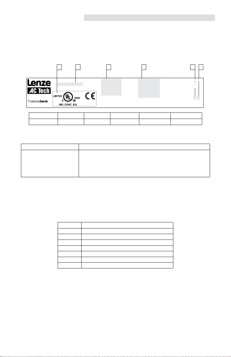
Drive Identification Label
INPUT:
Type:
E94P120Y2NES
ID-No: 13014745
Made in USA
Model 940
A B C D E F
Certifications Model Number Input Ratings Output Ratings Hardware Version Software Version
1(3)/PE
120/240 V
24.0 (13.9) A
50-60 HZ
13014745012345678
OUTPUT:
3/PE
0 - 230 V
12.0 A
For detailed information
refer to instruction
Manual: S94H201
SN: 13014745012345678
E94P120Y2NES0XX2###
Package Contents
Scope of Supply Important
1 Model PositionServo:
Type E94P or E94R
1 Mounting Instructions (English)
1 MotionView CD ROM including:
- configuration software
- documentation
After reception of the delivery, immediately check whether the scope of supply matches the
accompanying papers. Lenze-AC Tech does not accept any liability for deficiencies claimed
subsequently.
Claim:
- visible transport damage immediately to the forwarder
- visible deficiencies/incompleteness immediately to your Lenze representative.
Related Documents
The documentation listed herein contains information relevant to the operation of the PositionServo and MotionView
OnBoard. To obtain the latest documentation, visit the Download/Technical Documentaion section of http://www.
lenze.com.
Table 1: Reference Documentation
Document # Description
S94H201 PositionServo (with MVOB) HW V2 User Manual
PM94H201 PositionServo (with MVOB) Programming Manual
P94MOD01 Position Servo ModBus RTU over RS485 ; Modbus TCP/IP
P94CAN01 PositionServo CANopen Communications Reference Guide
P94DVN01 PositionServo DeviceNet Communications Reference Guide
P94ETH01 PositionServo EtherNet/IP Communications Reference Guide
P94PFB01 PositionServo PROFIBUS Communications Reference Guide
Copyright © 2013 - 2011 by Lenze AC Tech Corporation.
All rights reserved. No part of this manual may be reproduced or transmitted in any form without written permission
from Lenze AC Tech Corporation. The information and technical data in this manual are subject to change without
notice. Lenze AC Tech makes no warranty of any kind with respect to this material, including, but not limited to, the
implied warranties of its merchantability and fitness for a given purpose. Lenze AC Tech assumes no responsibility
for any errors that may appear in this manual and makes no commitment to update or to keep current the information
in this manual.
Page 3

Contents
1 Introduction ........................................................................................................................................2
1.1 Safety Information .....................................................................................................................2
1.2 Legal Regulations .....................................................................................................................2
1.3 Part Number Designation ..........................................................................................................3
1.4 Drive Connectors.......................................................................................................................4
2 Technical Data ...................................................................................................................................5
2.1 Electrical Characteristics ...........................................................................................................5
2.2 Connections and I/O ..................................................................................................................6
2.2.1 P1 - Input Power (Mains) Connection ......................................................................6
2.2.2 P7 - Output Power Connection ...............................................................................7
2.2.3 P2 - Ethernet Communications Port ........................................................................7
2.2.4 P3 - Controller I/O ..................................................................................................8
2.2.5 P4 - Motor Feedback ..............................................................................................9
2.2.6 P5 - 24 VDC Back-up Power Input ..........................................................................9
2.2.7 P6 - Braking Resistor and DC Bus ..........................................................................10
2.2.8 P8 - ISO 13849 Safety Circuit (Option) ....................................................................10
3 Installation..........................................................................................................................................12
3.1 PositionServo Dimensions .........................................................................................................13
3.2 Clearance for Cooling Air Circulation .........................................................................................14
3.3 Shielding and Grounding ...........................................................................................................14
3.4 Electrical Installation .................................................................................................................15
STOP!
BEFORE using the PositionServo drive, read the User Manual, S94H201 in its entirety.
The PositionServo User Manual, S94H201, can be found on the CD that came with
this drive and in the Download/Technical documentation section of www.lenze.com.
13433283_P94MI01D_EN 1
Page 4
Introduction
1 Introduction
1.1 Safety Information
DANGER!
Hazard of electrical shock! Circuit potentials are up to 480 VAC above earth ground. Avoid direct contact with the printed
circuit board or with circuit elements to prevent the risk of serious injury or fatality. Disconnect incoming power and wait 60
seconds before servicing drive. Capacitors retain charge after power is removed.
STOP!
DO NOT connect incoming power to the output motor terminals (U, V, W)! Severe damage to the PositionServo will result.
Check phase wiring (U, V, W) and thermal input (T1, T2) before powering up drive. If miswired, severe damage to the
PositionServo will result.
STOP!
Use only 10 V (peak to peak) or less resolvers (P4). Use of higher voltage resolvers may result in feedback failure and
damage to the drive.
WARNING!
Hazard of unintended operation! When the enable input remains asserted, the “Keep Alive” circuit (P5) will restart the
motor upon restoration of mains power. If this action is not desired, then remove the enable input prior to re-application
of input power.
1.2 Legal Regulations
Claim Description
Identification Nameplate CE Identification Manufacturer
Application
as directed
Liability
Warranty
Disposal
Lenze controllers are unambiguously designated by the
contents of the nameplate
E94P or E94R servo controller
• must only be operated under the conditions prescribed in these Instructions.
• are components for:
− Closed loop control of Velocity, Torque or Positioning applications with AC synchronous motors.
− installation in a machine.
− assembly with other components to form a machine.
• are electric units for installation in control cabinets or similarly enclosed housing.
• comply with the requirements of the Low-Voltage Directive.
• are not machines for the purpose of the Machinery Directive.
• are not to be used as domestic appliances, but only for industrial purposes.
Drive systems with E94P or E94R servo inverters
comply with the EMC Directive if they are installed according to the guidelines of CE-typical drive systems.
can be used for:
− operation on public and non-public mains
− operation in industrial premises and residential areas.
The user is responsible for the compliance of his application with the EC directives.
Any other use shall be deemed as inappropriate!
• The information, data, and notes in these instructions met the latest design and implementation of the drive at the time
of publication. Claims on modifications referring to controllers that have already been supplied cannot be derived from
the information, illustrations, and descriptions.
• The specifications, processes and circuitry described in these instructions are for guidance only and must be adapted to
your own specific application. Lenze does not take responsibility for the suitability of the process and circuit proposals.
• The specifications in these Instructions describe the product features without guaranteeing them.
• Lenze does not accept any liability for damage and operating interference caused by:
− Disregarding the operating instructions
− Unauthorized modifications to the controller
− Operating errors
− Improper working on and with the controller
Warranty conditions: refer to Lenze AC Tech Terms and Conditions of Sale, document TD03.
Material Recycle Dispose
Metal • -
Plastic • -
Assembled PCB’s - •
In compliance with the EC
Low-Voltage Directive
Lenze AC Tech Corporation
630 Douglas Street
Uxbridge, MA 01569 USA
2 13433283_P94MI01D_EN
Page 5
Introduction
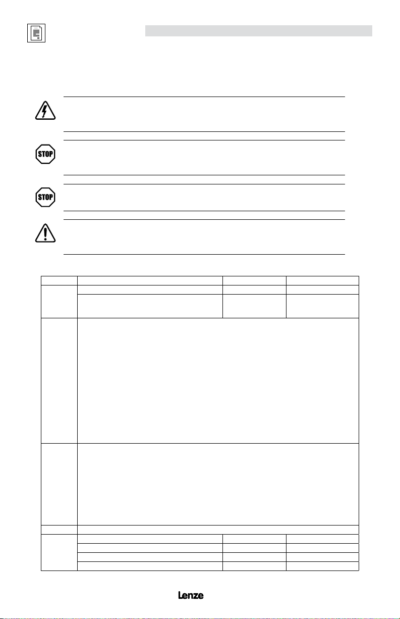
1.3 Part Number Designation
Table 3: Drive Type Number
Electrical Products in the 94x Series
E94
P = PositionServo Model 940 with Encoder Feedback
R = PositionServo Model 941 with Resolver Feedback
Drive Rating in Amps:
020 = 2 Amps 090 = 9 Amps
040 = 4 Amps 100 = 10 Amps
060 = 6 Amps 120 = 12 Amps
080 = 8 Amps 180 = 18 Amps
Input Phase:
S = Single Phase Input only
Y = Single or Three Phase Input
T = Three Phase Input only
Input Voltage:
1 = 120 VAC Doubler (120V, 1~ in/ 240V, 3~ out)
2 = 200/240 VAC
4 = 400/480 VAC
Line Filter:
N = No Line Filter*
F = Integrated Line Filter
Secondary Feedback:
E = Incremental Encoder
R = Standard Resolver
Safety Option:
M = MotionView OnBoard, no ISO 13849-1 safety compliance
S = MotionView OnBoard, with ISO 13849-1 safety compliance
* For 3-phase EMC installation, model 940 EMC footprint/side mount filters are required.
P 020 S 1 N E M
13433283_P94MI01D_EN 3
Page 6
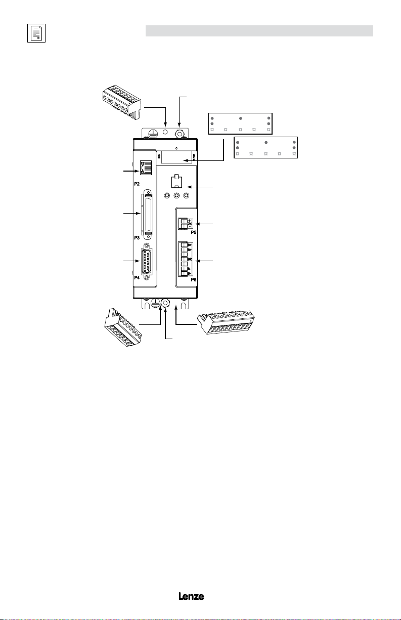
1.4 Drive Connectors
L3
L2
L1
Introduction
Ground Lug
P1
P2
P3
P4
P8
1
2
3
4
5
6
P1 Mains Power 3-pin or 4-pin removable terminal block
P2 Ethernet Port RJ45 connector
P3 I/O Connector 50-pin SCSI connector
- Buffered Encoder Output A, B & Z channels with compliments (5V @ 20mA)
- Digital Inputs 11 programmable plus 1 dedicated (5-24V))
- Digital Outputs 4 programmable plus 1 dedicated (5-24V @ 100mA)
- Analog Input 2 differential; ±10 VDC (12-bits each)
- Analog Output 1 single ended; ±10 VDC (10-bit)
- Position Reference Input Step & Direction or Master Encoder (TTL)
P4 Encoder Feedback (E94P drive) 15-pin D-shell connector
P4 Resolver Feedback (E94R drive) 9-pin D-shell connector
P5 24VDC Power “Keep Alive” 2-pin removable terminal block
P6 Regen and Bus Power 5-pin removable terminal block
P7 Motor Power 6-pin removable terminal block
P8 ISO 13849 Safety Circuit (Option) 6-pin removable terminal block
Ground Lug
T1
9
T2
EPM
P5
P6
P7
U
4
2
0
d
S
i
8
W
V
4 13433283_P94MI01D_EN
Page 7

Technical Data
2 Technical Data
2.1 Electrical Characteristics
Single-Phase Models
(1)
Type
E94_020S1N_~
E94_040S1N_~ 15 8.6 4.0 12 1.7 29 30
Mains Voltage
120V
E94_020S2F_~
E94_040S2F_~ -- 8.6 4.0 12 1.7 29 30
E94_080S2F_~ -- 15.0 8.0 24 3.3 61 63
(80 V -0%...264 V +0%)
E94_100S2F_~ -- 18.8 10.0 30 4.2 80 85
Single/Three-Phase Models
(1)
Type
E94_020Y2N_~
E94_040Y2N_~ 8.6 5.0 4.0 12 1.7 29 30
E94_080Y2N_~ 15.0 8.7 8.0 24 3.3 61 63
E94_100Y2N_~ 18.8 10.9 10.0 30 4.2 80 85
E94_120Y2N_~ 24.0 13.9 12.0 36 5.0 114 129
E94_180T2N_~
E94_020T4N_~
E94_040T4N_~ -- 5.5 4.0 12 3.3 50 73
E94_060T4N_~ -- 7.9 6.0 18 5.0 93 122
E94_090T4N_~ -- 12.0 9.0 27 7.5 138 182
Mains Voltage
(80 V -0%...264 V +0%)
(180 V -0%...264 V +0%)
(320 V -0%...528 V +0%)
(1) The first “_” equals “P” for the 940 encoder based drive or “R” for the 941 resolver based drive.
The second “_” equals “E” for incremental encoder (E94P drive) or “R” for the standard resolver (E94R drive).
The last digit “~” equals “M” for MV OnBoard and no ISO 13849-1 circuit or “S” for MV OnBoard plus the ISO 13849-1 circuit.
(2)
Mains voltage for operation on 50/60 Hz AC supplies (48 Hz -0% … 62Hz +0%).
(3) Connection of 120VAC (70 V … 132 V) to input power terminals L1 and N on these models doubles the voltage on motor output terminals U-V-W for use
with 230VAC motors.
(4) Connection of 120VAC or 240VAC to input power terminals L1 and L2 on these models delivers an equal voltage as maximum to motor output terminals
U-V-W allowing operation with either 120VAC or 230VAC motors.
(5) Drive rated at 8kHz Carrier Frequency. Derate Continuous current by 17% at 16kHz.
(6)
Peak RMS current allowed for up to 2 seconds. Peak current rated at 8kHz. Derate by 17% at 16kHz.
(7)
Derate rated output current and peak output current by 2.5% for every ºC above 40ºC up to 55ºC maximum.
(8) At 240 VAC line input for drives with suffixes “S1N”, “S2F”, “Y2N”. At 480 VAC line input for drives with suffixes “T4N”.
a. The output power is calculated from the formula: output kVA = [(3) x ULL x I
b. The actual output power (kW) depends on the motor in use due to variations in motor rated voltage, rated speed and power factor, as well as
c. Typical max continuous power (kW) for PM servo motors run 50-70% of the kVA ratings listed.
(2)
1~
Mains
Current
(doubler)
Mains
Current
(Std.)
A A A A kVA mA W W
(3)
or 240V
9.7 5.0 2.0 6 0.8
(4)
-- 5.0 2.0 6 0.8 19 21
(4)
120 / 240V
(2)
1~
Mains
Current
Mains
Current
A A A A kVA mA W W
5.0 3.0 2.0 6 0.8
(4)
120 / 240V
1~ or 3~
240V
3~
-- 19.6 18.0 54 7.5 171 195
-- 2.7 2.0 6 1.7 31 41
400 / 480V
3~
actual max operating speed and desired overload capacity.
1~
Rated
Output
Current
Peak
Output
Leakage
Output
Power
(5)
Current
(6)
at Rated
Output
Current
(8)
(8kHz)
Current
Power
Loss at
Rated
Output
Current
(8kHz)
(5)
(16 kHz)
19 21
>3.5
3~
Rated
Output
Current
Peak
Output
Leakage
Output
Power
(5)
Current
(6)
at Rated
Output
Current
(8)
(8kHz)
Current
Power
Loss at
Rated
Output
Current
(8kHz)
(5)
(16 kHz)
19 21
>3.5
] / 1000
rated
Power
Loss at
Rated
Output
Current
Power
Loss at
Rated
Output
Current
(5)
(5)
13433283_P94MI01D_EN 5
Page 8

Technical Data
1
4
1
4
2.2 Connections and I/O
2.2.1 P1 - Input Power (Mains) Connection
Standard Models
Pin Name Function Name Function
1 PE Protective Earth (Ground) PE Protective Earth (Ground)
2 L1 AC Power in N AC Power Neutral (120V Doubler only)
3 L2 AC Power in L1 AC Power in
4 L3 AC Power in (3~ models only) L2/N AC Power in (non-doubler operation)
Fuse PE L1, L2, L3
Type
E94_020S1N_~ M20/M10 C20/C10 20/10
E94_040S1N_~ M32/M20 C32/C20 30/20
E94_020S2F_~ M20 C20 20
E94_040S2F_~ M20 C20 20
E94_080S2F_~ M32 C32 32
E94_100S2F_~ M40 C40 40
E94_020Y2N_~ M20/M16 C20/C16 20/15
E94_040Y2N_~ M20/M16 C20/C16 20/15
E94_080Y2N_~ M32/M20 C32/C20 30/20
E94_100Y2N_~ M32/M20 C32/C20 30/20
E94_120Y2N_~ M50/M32 C50/C32 50/30
E94_180T2N_~ M40 C40 40
E94_020T4N_~ M10 C10 10
E94_040T4N_~ M10 C10 10
E94_060T4N_~ M20 C20 20
E94_090T4N_~ M25 C25 25
1) Installations with high fault current due to large supply mains may require a type D circuit breaker.
2) UL Class CC or T fast-acting current-limiting type fuses, 200,000 AIC, preferred. Bussman KTK-R, JJN, JJS or equivalent.
3) Thermal-magnetic type breakers preferred.
WARNING!
The PositionServo drive runs on phase-to-phase voltage. For the standard drive, either a delta or wye transformer may be used for
3-phase input. However, for reinforced insulation of user accessible I/O circuits, each phase voltage to ground must be less than or
equal to 300VAC rms. This means that the power system must use center grounded wye secondary configuration for 400/480VAC
mains.
EN 60204 UL
[A]
1~/3~
[A]
1~/3~
3
L3
L2
L1
1) 2)
[A]
1~/3~
2
PE
3)
[mm2]
[AWG]
Doubler Models
[mm]
[in]
2.5
14
0.25
4
12
2.5
14
4
0.25
12
6
10
2.5
14
4
12
6
0.25
10
6
10
6
10
2.5
1460.25
[mm2]
[Nm]
[AWG]
[lb-in]
1~/3~
2.5/2.5
0.5
4.5
0.5
4.5
0.5
4.5
0.79
0.5
4.5
7
14/14
4/2.5
12/14
2.5
14
4
12
6
10
2.5/2.5
14/14
4/2.5
12/14
6/2.5
10/14
6/4
10/12
6
10
2.5
1460.25
6
6
6
[mm]
[in]
0.25
0.25
0.25
3
L1
[Nm]
[lb-in]
0.5
4.5
0.5
4.5
0.5
4.5
0.79
0.5
4.5
0.79
0.5
4.5
2
N
PE
7
7
L2/N
6
6
6
STOP!
For the E94 _020S1N_~ and E94_040S1N_~ doubler models, do NOT apply 240VAC to the N and L1 terminals. Severe damage to
the drive will result.
6 13433283_P94MI01D_EN
Page 9

Technical Data
1
6
ETHERNET
1
8
P2
2.2.2 P7 - Output Power Connection
STOP!
DO NOT connect incoming power to the output motor terminals (U, V, W)! Severe damage to the PositionServo will result.Check phase
wiring (U, V, W) and thermal input (T1, T2) before powering up drive. If miswired, severe damage to the PositionServo will result.
Type
E94_020S1N_~
E94_040S1N_~
E94_020S2F_~
E94_040S2F_~
E94_080S2F_~
E94_100S2F_~
E94_020Y2N_~
E94_040Y2N_~
E94_080Y2N_~
E94_120Y2N_~
E94_180T2N_~
E94_020T4N_~
E94_040T4N_~
E94_060T4N_~
E94_090T4N_~
Pin Terminal Function
1 T1 Thermistor (PTC) Input
2 T2 Thermistor (PTC) Input
3 U Motor Power Out
4 V Motor Power Out
5 W Motor Power Out
6
[mm2]
[AWG]
0.8
18
0.8
18
0.8
18
0.8
18
0.8
18
0.8
18
0.8
18
0.8
18
0.8
18
Protective Earth (Chassis Ground)
PE
T1, T2 U, V, W PE
[mm]
[Nm]
[in]
[lb-in]
0.5
4.5
6
0.25
0.25
0.25
0.25
0.5
4.5
6
0.5
4.5
0.5
4.5
6
0.56-0.79
5.0-7.0
6
0.5
4.5
[mm2]
[AWG]
1.5
16
1.5
16
1.5
16
2.5
14
1.5
16
2.5
14
6.0
10
1.5
16
2.5
14
[mm]
[in]
0.25
0.25
0.25
0.25
5
4
W
[Nm]
[lb-in]
0.5
4.5
6
0.5
4.5
6
0.5
4.5
0.5
4.5
6
0.56-0.79
5.0-7.0
6
0.5
4.5
3
V
U
[mm2]
[AWG]
1.5
16
1.5
16
1.5
16
2.5
14
1.5
16
2.5
14
6.0
10
1.5
16
2.5
14
2
T2
T1
[mm]
[Nm]
[in]
[lb-in]
0.5
4.5
6
0.25
0.25
0.25
0.25
0.5
4.5
6
0.5
4.5
0.5
4.5
6
0.56-0.79
5.0-7.0
6
0.5
4.5
NOTE: Terminals T1 and T2 are used for motors with a thermistor only.
The PositionServo does not provide motor over-temperature protection. The user may connect a KTY motor thermal sensor to
the drive as detailed in section 4.1.1 and 4.5.2 of manual S94H201 if necessary to satisfy NEC requirements.
NOTE
Encoder cables manuafactured by Lenze AC Tech use 18 AWG wire for the T1 and T2 connectors. Customer-manufactured
cables may use a different AWG wire for the T1 and T2 connectors.
2.2.3 P2 - Ethernet Communications Port
Pin Name Function
1 + TX Transmit Port (+) Data Terminal
2 - TX Transmit Port (-) Data Terminal
3 + RX Receive Port (+) Data Terminal
4 N.C.
13433283_P94MI01D_EN 7
5 N.C.
6 - RX Receive Port (-) Data Terminal
7 N.C.
8 N.C.
Page 10

Technical Data
50
26
2.2.4 P3 - Controller I/O
Pin Name Function
1 MA+ Master Encoder A+ / Step+ input 26 IN_A_COM Digital input group A COM terminal
2 MA- Master Encoder A- / Step- input 27 IN_A1 Digital input A1
3 MB+ Master Encoder B+ / Direction+ input 28 IN_A2 Digital input A2
4 MB- Master Encoder B- / Direction- input 29 IN_A3 Digital input A3
5 GND Drive Logic Common 30 IN_A4 Digital input A4
6 5+ +5V output (max 100mA) 31 IN_B_COM Digital input group B COM terminal
7 BA+ Buffered Encoder Output: Channel A+ 32 IN_B1 Digital input B1
8 BA- Buffered Encoder Output: Channel A- 33 IN_B2 Digital input B2
9 BB+ Buffered Encoder Output: Channel B+ 34 IN_B3 Digital input B3
10 BB- Buffered Encoder Output: Channel B- 35 IN_B4 Digital input B4
11 BZ+ Buffered Encoder Output: Channel Z+ 36 IN_C_COM Digital input group C COM terminal
12 BZ- Buffered Encoder Output: Channel Z- 37 IN_C1 Digital input C1
13 no connection 38 IN_C2 Digital input C2
14 no connection 39 IN_C3 Digital input C3
15 no connection 40 IN_C4 Digital input C4
16 no connection 41 RDY+ Ready output Collector
17 no connection 42 RDY- Ready output Emitter
18 no connection 43 OUT1-C Programmable output #1 Collector
19 no connection 44 OUT1-E Programmable output #1 Emitter
20 AIN2+ Positive (+) of Analog signal input 45 OUT2-C Programmable output #2 Collector
21 AIN2- Negative (-) of Analog signal input 46 OUT2-E Programmable output #2 Emitter
22 ACOM Analog common 47 OUT3-C Programmable output #3 Collector
23 AO Analog output (max 10 mA) 48 OUT3-E Programmable output #3 Emitter
24 AIN1+ Positive (+) of Analog signal input 49 OUT4-C Programmable output #4 Collector
25 AIN1 - Negative (-) of Analog signal input 50 OUT4-E Programmable output #4 Emitter
P3
1
CONTROLLER I/O
25
50-pin SCSI connector
Digital Input A3
For the drive to function, an ENABLE input must be wired to the drive, and should be connected to IN_A3, (P3.29),
which is, by the default the ENABLE input on the drive. This triggering mechanism can either be a switch or an input
from an external PLC or motion controller. The input can be wired either sinking or sourcing. The Enable circuit will
accept 5-24V control voltage.
Pin Name Function
Digital and Analog I/O Ratings
I/O Scan Times Linearity Temperature Drift Offset Current Input Impedance Voltage Range
Units
Digital Inputs
Digital Outputs
Analog Inputs
Analog Outputs
(1) Inputs do not have scan time. Their values are read directly by indexer program statement.
ms % % % mA Ohm VDC
(1)
512
512 100 max N/A 30 max
512 ± 0.013 0.1% per °C rise
512 0.1% per °C rise
De-bounce time is programmable and can be set as low as 0. Propagation delay is typically 20 us
adjustable
adjustable
± 0
± 0
Depend on
load
Depend on
load
10 max N/A ± 10
2.4 k 5-24
47 k ± 10
8 13433283_P94MI01D_EN
Page 11

2.2.5 P4 - Motor Feedback
ENCODER
P4
15
RESOLVER
P4
9
6
+
Type Pin Name Function
1 EA+ Encoder Channel A+ Input
2 EA- Encoder Channel A- Input
3 EB+ Encoder Channel B+ Input
4 EB- Encoder Channel B- Input
5 EZ+ Encoder Channel Z+ Input
6 EZ- Encoder Channel Z- Input
7 GND Drive Logic Common/Encoder Ground
E94P
8 SHLD Shield
9 PWR Encoder supply (+5VDC)
10 HA- Hall Sensor A- Input
11 HA+ Hall Sensor A+ Input
12 HB+ Hall Sensor B+ Input
13 HC+ Hall Sensor C+ Input
14 HB- Hall Sensor B- Input
15 HC- Hall Sensor C- Input
Pin Name Function
1 Ref +
2 Ref -
3 N/C No Connection
4 Cos+
E94R
5 Cos-
6 Sin+
7 Sin-
8 PTC+
9 PTC-
Technical Data
Resolver reference connection
Resolver Cosine connections
Resolver Sine connections
Motor PTC Temperature Sensor
1
9
8
1
5
2.2.6 P5 - 24 VDC Back-up Power Input
Pin Name Function
[mm2]
[AWG]
1 +24 VDC Positive 24 VDC Input (500mA)
2 Return 24V power supply return
WARNING!
Hazard of unintended operation! When the enable input remains asserted, the “Keep Alive”
circuit will restart the motor upon restoration of mains power. If this action is not desired,
then remove the enable input prior to re-application of input power.
13433283_P94MI01D_EN 9
[mm]
1.5
16
0.25
[Nm]
[in]
[lb-in]
-
6
0.5
4.5
+
24
-
Page 12

Technical Data
B+
B-
BR
B-
B+
1
P1
P2
P3
P4
P5
P6
2.2.7 P6 - Braking Resistor and DC Bus
Pin Terminal Function
[mm2]
[mm]
1 B+
2 B+
3 BR Brake Resistor
4 B-
5 B-
* For E94_120Y2N_~ and E94_180T2N_~ models use:
Positive DC Bus / Brake Resistor
Negative DC Bus
[AWG]
2.5*
146*0.25
4
1260.25
2.2.8 P8 - ISO 13849 Safety Circuit (Option)
STOP!
BEFORE using P8, read the COMPLETE DETAILED INSTRUCTIONS for the ISO 13849-1 Safety Circuit in Se ction 4.1. 8 of
manual S94H201 (PositionServo Users Manual on the accompanying CD and www.lenzeamericas.com).
If installed, the ISO 13849-1 Safety Circuit connector, P8, is located on the bottom of the PositionServo. P8, a 6-pin
quick-connect terminal block. This option provides additional inputs to disable the drive output so that the drive
cannot cause torque to be generated in the motor. This safety function known as “Safe Torque Off” meets the
requirements of the following standard: ISO 13849-1 Safety of Machinery, Safety-related Parts of Control Systems,
Category (Cat.) 3, Performance Level (PL) d and Safety Integrity Level (SIL) 2, per EN 61800-5-2 2007.
Pin Name Function
[mm2]
1 Bypass Voltage ISO 13849-1 Bypass Voltage (+24VDC)
2 Bypass COM ISO 13849-1 Bypass Common
3 Safety Status ISO 13849-1 Safety Status
4 Safety Input1 ISO 13849-1 Safety Input 1 (+24VDC to Enable)
5 Safety COM ISO 13849-1 Safety Common
6 Safety Input2 ISO 13849-1 Safety Input 2 (+24VDC to Enable)
[AWG]
1.5
1660.25
[Nm]
[in]
[lb-in]
0.5*
4.5
0.5
4.5
[mm]
[Nm]
[in]
[lb-in]
0.5
4.5
2
1
2
6
5
4
3
6
5
4
3
WARNING!
The drive is supplied from the factory with the ISO 13849-1 safety circuit enabled. The drive is not operational until +24V
is present at terminals 4 and 6. For the proper safety connections, refer to the “Connection of Two Safety Circuits with
External +24V Supply” diagram. Under certain applications when safety connections are not required the drive may be
operated with the safety circuit disabled. The diagram below illustrates how to bypass the safety circuit.
Wiring Diagram to Bypass ISO 13849-1 Safety Circuit
Pin Name Function
1 Bypass Voltage ISO 13849-1 Bypass Voltage (+24VDC)
2 Bypass COM ISO 13849-1 Bypass Common
3 Safety Status ISO 13849-1 Safety Status
4 Safety Input1 ISO 13849-1 Safety Input 1 (+24VDC to Enable)
5 Safety COM ISO 13849-1 Safety Common
6 Safety Input2 ISO 13849-1 Safety Input 2 (+24VDC to Enable)
*1 – This voltage must under no circumstances be used to supply the ISO 13849-1 Safety circuits (terminals 3 to 6). This voltage is intending only for use in bypassing
(disabling) the ISO 13849-1 circuits should they not be required.
*2 – A Separate +24VDC supply providing reinforced isolation (SELV or PELV), must be supplied to operate these inputs. This supply should not be floating but should
be referenced within 20V peak of PE at the drive.
WARNING!
It is required that all information contained within this ISO 13849-1 standard be observed when implementing any
part of this safety circuit functionality with the PositionServo drive.
10 13433283_P94MI01D_EN
*1
*1
*2
*2
*2
Page 13

Technical Data
P2
P3
P6
-
P2
+
-
STOP!
This is only partial information on the ISO 13849-1 Safety Circuit. BEFORE using P8, read the COMPLETE DETAILED INSTRUCTIONS
for the ISO 13849-1 Safety Circuit in Section 4.1.8 of manual S94H201 (PositionServo Users Manual on the accompanying
CD and www.lenzeamericas.com).
Due to ISO 13849-1 regulations, a separate +24VDC external dedicated safety power supply must be provided to
the drive Safety circuits. The bypass +24V supply is intended for bypass purposes only and must not be used as the
control voltage to these circuits.
Installation and Connection
Connection of Two Safety Circuits with External +24V Supply
Pin Name Function
1 Bypass Voltage ISO 13849-1 Bypass Voltage (+24VDC)
2 Bypass COM ISO 13849-1 Bypass Common
3 Safety Status ISO 13849-1 Safety Status * 100mA max
4 Safety Input1 ISO 13849-1 Safety Input 1 (+24VDC to Enable)
5 Safety COM ISO 13849-1 Safety Common
6 Safety Input2 ISO 13849-1 Safety Input 2 (+24VDC to Enable)
Evaluation and Testing of the ISO 13849-1 Safety Circuit
As part of the regulations for ISO 13849-1 safety circuit provision must be made for the user to periodically test the
safety circuits and that testing should be capable of identifying a single fault. The PositionServo drive uses the safety
status output (Pin 3) in conjunction with the display of the drive to allow the testing of the safety circuits.
The safety status output becomes active to indicate partial or full enable of the safety input circuits 1 and 2. If safety
input 1 or safety input 2 or both inputs are on then the safety status output will become active. The safety status
output must be connected to some visible indication for the operator to reference during test of the circuit.
As well as being used to test the correct operation of the safety circuits the safety status output can be used as an
indicator that the drive has been placed in the fully shut down condition (all safety circuits off). For example, if both
Safety Inputs have been Deactivated, the Safety Status is also Deactivated. If one of the Safety Inputs signals failed
to call for a shutdown, or if one of the Safety Circuits failed to shut down, the Safety Status signal remains Asserted
to alert the operator to the problem.
The procedure for testing the ISO 13849-1 safety circuit and the identification of a single fault on the system is given
below. The safety status output should be connected to a visible indicator (such as a lamp or LED) so the operator
can interpret its condition.
NOTE
Customer must size load so as not to pull more than 100mA.
Safety Output Status Indication
Pin Name Function
1 Bypass Voltage ISO 13849-1 Bypass Voltage (+24VDC)
2 Bypass COM ISO 13849-1 Bypass Common
3 Safety Status ISO 13849-1 Safety Status * 100mA max
4 Safety Input1 ISO 13849-1 Safety Input 1 (+24VDC to Enable)
5 Safety COM ISO 13849-1 Safety Common
6 Safety Input2 ISO 13849-1 Safety Input 2 (+24VDC to Enable)
P1
P4
P5
P1
P3
P4
P5
P6
External
+24VDC
Safety Circuit
Input 1
Safety Circuit
Input 2
Safety Circuit
Input 1
Safety Circuit
Input 2
+
External
+24VDC
Safety Output
Status Indication
13433283_P94MI01D_EN 11
Page 14

3 Installation
DANGER!
Hazard of electrical shock! Circuit potentials are up to 480 VAC above earth ground.
Avoid direct contact with the printed circuit board or with circuit elements to prevent the
risk of serious injury or fatality. Disconnect incoming power and wait 60 seconds before
servicing drive. Capacitors retain charge after power is removed.
STOP!
• The PositionServo must be mounted vertically for safe operation and to ensure
enough cooling air circulation.
• Printed circuit board components are sensitive to electrostatic fields. Avoid
contact with the printed circuit board directly. Hold the PositionServo by its case
only.
• Protect the drive from dirt, filings, airborne particles, moisture, and accidental
contact. Provide sufficient room for access to the terminal block.
• Mount the drive away from any and all heat sources. Operate within the
specified ambient operating temperature range. Additional cooling with an
external fan may be required in certain applications.
• Avoid excessive vibration to prevent intermittent connections
• DO NOT connect incoming (mains) power to the output motor terminals (U, V,
W)! Severe damage to the drive will result.
• Do not disconnect any of the motor leads from the PositionServo drive unless
(mains) power is removed. Opening any one motor lead may cause failure.
• Control Terminals provide basic isolation (insulation per EN 61800-5-1).
Protection against contact can only be ensured by additional measures, e.g.,
supplemental insulation.
• Do not cycle mains power more than once every 2 minutes. Otherwise damage
to the drive may result.
Installation
WARNING!
For compliance with EN 61800-5-1, the following warning applies.
This product can cause a d.c. current in the protective earthing conductor. Where
a residual current-operated protective (RCD) or monitoring (RCM) device is used for
protection in case of direct or indirect contact, only an RCD or RCM of Type B is
allowed on the supply side of this product.
UL INSTALLATION INFORMATION
• Suitable for use on a circuit capable of delivering not more than 200,000 rms
symmetrical amperes, at the maximum voltage rating marked on the drive.
• Use Class 1 wiring with minimum of 75ºC copper wire only.
• Shall be installed in a pollution degree 2 macro-environment.
• The PositionServo does not provide motor over-temperature protection.
The user may connect a KTY motor thermal sensor to the drive as detailed
in section 4.1.1 and 4.5.2 of manual S94H201 if necessary to satisfy NEC
requirements.
12 13433283_P94MI01D_EN
Page 15

Installation
3.1 PositionServo Dimensions
34
12
12
15
C
(1)
Type
E94_020S1N_~ 68 190 190 182 1.1
E94_040S1N_~ 69 190 190 182 1.2
E94_020S2F_~ 68 190 235 182 1.3
E94_040S2F_~ 69 190 235 182 1.5
E94_080S2F_~ 87 190 235 182 1.9
E94_100S2F_~ 102 190 235 182 2.2
E94_020Y2N_~ 68 190 190 182 1.3
E94_040Y2N_~ 69 190 190 182 1.5
E94_080Y2N_~ 95 190 190 182 1.9
E94_100Y2N_~ 114 190 190 182 2.2
E94_120Y2N_~ 68 190 235 182 1.5
E94_180T2N_~ 68 242 235 233 2.0
E94_020T4N_~ 68 190 190 182 1.5
E94_040T4N_~ 95 190 190 182 1.9
E94_060T4N_~ 68 190 235 182 1.4
E94_090T4N_~ 68 242 235 233 2.0
(1) The first “_” equals “P” for the Model 940 encoder based drive or “R” for the Model 941 resolver based drive.
The second “_” equals “E” for incremental encoder (must have E94P drive) or “R” for the standard resolver (must have E94R drive).
The last digit “~” equals M” for MV OnBoard and no ISO 13849-1 circuit or “S” for MV OnBoard plus the ISO 13849-1 circuit.
Dimensions in mm
A
(mm)B(mm)C(mm)D(mm)
38
dia = 4.57
4.57
A
Weight
(kg)
D B
S923
13433283_P94MI01D_EN 13
Page 16

Installation
3.2 Clearance for Cooling Air Circulation
Additional Clearance is required:
• for side mount and rear mount AC line filters
• if there are other accessories installed
• for cables and wires connected to the top, front and bottom of
the drive
• when the drive is mounted adjacent to noise sensitive equipment
or clean wire ways
>3mm
>25mm
>25mm
>3mm
3.3 Shielding and Grounding
• Use single-point grounding (SPG) for panel-mounted controls.
• Tie the SPG for all enclosures to earth ground at the same point.
• Individually connect the system ground and equipment grounds for all panel-mounted enclosures to the SPG
for that panel using 14 AWG (2.5 mm2) or larger wire.
• Ground the chassis to the mounting. Use 14 AWG (2.5 mm2) or larger wire to join the enclosure to earth ground.
• Install a lock washer between the enclosure and ground terminal. For maximum contact between the terminal
and enclosure, remove paint in a minimum radius of 0.25 in (6 mm) around the screw hole of the enclosure.
• Ground the shielded cable at both the drive end and at the motor end.
• If the PositionServo drive continues to pick up noise after grounding the shield, add an AC line filtering device
and/or an output filter (between the drive and servo motor).
EMC
Compliance with EN 61800-3:2004 In a domestic environment this product may cause radio interference. The
user may be required to take adequate measures
Noise emission
Installation according to EMC Requirements
Drive Models ending in the suffix “2F” are in compliance with
class A limits according to EN 55011 if installed in a control
cabinet and the motor cable length does not exceed 10m.
Models ending in “N” will require an appropriate line filter.
Screen clamps
A
Control cable
B
Low-capacitance motor cable
C
F
(core/core < 75 pF/m, core/screen < 150 pF/m)
Earth grounded conductive mounting plate
D
Encoder/Resolver Feedback Cable
E
Footprint or Sidemount Filter (optional)
F
14 13433283_P94MI01D_EN
A
EDB C
S930
Page 17

Installation
Drive
PC/Laptop
P6
P5
3.4 Electrical Installation
These are quick connect instructions only. Consult PositionServo User Manual S94H201 for full connection details.
Step Action Description
1 Connect the Drive’s Ethernet port P2 to
your PC’s Ethernet port.
2 Apply power to the drive and wait until
“diS” shows on the display.
3 Confirm that the PC and the drive have
the correct IP setting. (S94H201, section
6.2.2).
Ethernet Port
8
CAT 5e cable
d
i
P2
P3
P4
S
4 Launch MotionView software on your
computer via a web browser.
5 From the main toolbar select [Connect]
6 In the Connect dialog box, click [Discover]
to ping the network for any drives. If a
drive is located the address will appear
in the dialog box. If no address appears
then you can type the IP address in.
The default address for the drive is
192.168.124.120. Click [Connect] to
connect to the drive
7 Once connected, the drive name and
identifier are displayed in the upper lefthand corner of the Parameter Window.
13433283_P94MI01D_EN 15
Page 18

Page 19

Page 20

LenzeAmericasCorporation•LenzeACTechCorporation
630DouglasStreet•Uxbridge,MA01569•USA
Sales:(800)217-9100•Service(508)2789100
www.lenze.com
P94MI01D
 Loading...