

Page 1
EDK94AZRS6
.OdJ
L−force Drives
Montageanleitung
Mounting Instructions
Instructions de montage
Ä.OdJä
Instrucciones para el montaje
Istruzioni per il montaggio
9400 54 ... 95 A
E94AZRS0544, E94AZRS0954
Funk−Entstörfilter
RFI filter
Filtre antiparasite
Filtro RFI
Filtro RFI
Page 2

Lesen Sie zuerst diese Anleitung und die Dokumentation zum
Grundgerät, bevor Sie mit den Arbeiten beginnen!
Beachten Sie die enthaltenen Sicherheitshinweise.
Please read these instructions and the documentation of the standard
device before you start working!
Observe the safety instructions given therein!
Lire le présent fascicule et la documentation relative à l’appareil de base
avant toute manipulation de l’équipement !
Respecter les consignes de sécurité fournies.
Lea estas instrucciones y la documentación del equipo básico antes de
empezar a trabajar.
Observe las instrucciones de seguridad indicadas.
Prima di iniziare qualsiasi intervento, leggere le presenti istruzioni e la
documentazione relativa al dispositivo di base.
Osservare le note di sicurezza.
Page 3

Inhalt i
1 Über diese Dokumentation 4. . . . . . . . . . . . . . . . . . . . . . . . . . . . . . . . . . . . . . . . .
1.1 Informationen zur Gültigkeit 4. . . . . . . . . . . . . . . . . . . . . . . . . . . . . . . . .
1.2 Zielgruppe 4. . . . . . . . . . . . . . . . . . . . . . . . . . . . . . . . . . . . . . . . . . . . . . . .
1.3 Dokumenthistorie 5. . . . . . . . . . . . . . . . . . . . . . . . . . . . . . . . . . . . . . . . . .
1.4 Verwendete Konventionen 5. . . . . . . . . . . . . . . . . . . . . . . . . . . . . . . . . . .
1.5 Verwendete Hinweise 6. . . . . . . . . . . . . . . . . . . . . . . . . . . . . . . . . . . . . . .
2 Sicherheitshinweise 8. . . . . . . . . . . . . . . . . . . . . . . . . . . . . . . . . . . . . . . . . . . . . . .
2.1 Allgemeine Sicherheitshinweise 8. . . . . . . . . . . . . . . . . . . . . . . . . . . . . .
2.2 Restgefahren 9. . . . . . . . . . . . . . . . . . . . . . . . . . . . . . . . . . . . . . . . . . . . . .
3 Produktbeschreibung 10. . . . . . . . . . . . . . . . . . . . . . . . . . . . . . . . . . . . . . . . . . . . .
3.1 Lieferumfang 10. . . . . . . . . . . . . . . . . . . . . . . . . . . . . . . . . . . . . . . . . . . . . .
3.2 Übersicht 10. . . . . . . . . . . . . . . . . . . . . . . . . . . . . . . . . . . . . . . . . . . . . . . . .
3.3 Identifikation 11. . . . . . . . . . . . . . . . . . . . . . . . . . . . . . . . . . . . . . . . . . . . . .
3.4 Einsatzbedingungen 11. . . . . . . . . . . . . . . . . . . . . . . . . . . . . . . . . . . . . . . .
4 Technische Daten 12. . . . . . . . . . . . . . . . . . . . . . . . . . . . . . . . . . . . . . . . . . . . . . . . .
4.1 Allgemeine Daten und Einsatzbedingungen 12. . . . . . . . . . . . . . . . . . . .
4.2 Bemessungsdaten 14. . . . . . . . . . . . . . . . . . . . . . . . . . . . . . . . . . . . . . . . . .
4.3 Mechanische Daten 15. . . . . . . . . . . . . . . . . . . . . . . . . . . . . . . . . . . . . . . .
5 Mechanische Installation 16. . . . . . . . . . . . . . . . . . . . . . . . . . . . . . . . . . . . . . . . . . .
5.1 Wichtige Hinweise 16. . . . . . . . . . . . . . . . . . . . . . . . . . . . . . . . . . . . . . . . . .
5.2 Standardmontage 17. . . . . . . . . . . . . . . . . . . . . . . . . . . . . . . . . . . . . . . . . .
5.2.1 Bohrplan 17. . . . . . . . . . . . . . . . . . . . . . . . . . . . . . . . . . . . . . . . .
5.2.2 Montageschritte 18. . . . . . . . . . . . . . . . . . . . . . . . . . . . . . . . . .
5.3 Montagevariante 19. . . . . . . . . . . . . . . . . . . . . . . . . . . . . . . . . . . . . . . . . . .
5.3.1 Bohrplan 19. . . . . . . . . . . . . . . . . . . . . . . . . . . . . . . . . . . . . . . . .
5.3.2 Montageschritte 20. . . . . . . . . . . . . . . . . . . . . . . . . . . . . . . . . .
6 Elektrische Installation 21. . . . . . . . . . . . . . . . . . . . . . . . . . . . . . . . . . . . . . . . . . . . .
6.1 Wichtige Hinweise 21. . . . . . . . . . . . . . . . . . . . . . . . . . . . . . . . . . . . . . . . . .
6.2 Anschlussplan 23. . . . . . . . . . . . . . . . . . . . . . . . . . . . . . . . . . . . . . . . . . . . .
6.3 Anschlussdaten 24. . . . . . . . . . . . . . . . . . . . . . . . . . . . . . . . . . . . . . . . . . . .
6.4 Montageschritte 24. . . . . . . . . . . . . . . . . . . . . . . . . . . . . . . . . . . . . . . . . . .
EDK94AZRS6 DE/EN/FR/ES/IT 7.0
3
Page 4

1
Über diese Dokumentation
Informationen zur Gültigkeit
1 Über diese Dokumentation
0Abb. 0Tab. 0
1.1 Informationen zur Gültigkeit
Diese Anleitung ist gültig für
ƒ Funk−Entstörfilter E94AZRS0544
ƒ Funk−Entstörfilter E94AZRS0954
1.2 Zielgruppe
Diese Dokumentation richtet sich an qualifiziertes Fachpersonal nach
IEC 60364.
Qualifiziertes Fachpersonal sind Personen, die für die auszuführenden Tätigkeiten bei der Aufstellung, Montage, Inbetriebsetzung und dem Betrieb des Produkts über entsprechende Qualifikationen verfügen.
Tipp!
Informationen und Hilfsmittel rund um die Lenze−Produkte finden
Sie im Download−Bereich unter
www.lenze.com
4
EDK94AZRS6 DE/EN/FR/ES/IT 7.0
Page 5
1.3 Dokumenthistorie
Materialnummer Version Beschreibung
.OdJ 7.0 09/2014 TD15 UL−Hinweise in französischer Sprache für Ca-
13429260 6.0 04/2013 TD06 Überarbeitung
13348755 5.0 09/2010 TD29 Neuauflage wegen Neuorganisation des Un-
13237063 4.0 02/2008 TD29 Überarbeitung
13218947 3.0 09/2007 TD29 Überarbeitung
13204554 2.0 04/2007 TD29 Überarbeitung, 5−sprachig
13169226 1.0 11/2006 TD29 Erstausgabe
1.4 Verwendete Konventionen
Informationsart Auszeichnung Beispiele/Hinweise
Zahlenschreibweise
Dezimaltrennzeichen Punkt Es wird generell der Dezimalpunkt
Warnhinweise
UL−Warnhinweise
UR−Warnhinweise
Textauszeichnung
Programmname » « PC−Software
Symbole
Seitenverweis Verweis auf eine andere Seite mit
Dokumentationsverweis Verweis auf eine andere Dokumen-
Über diese Dokumentation
Dokumenthistorie
nada
EAC−Konformität
allgemeine Korrekturen
ternehmens, Layout−Anpassung und Überarbeitung
verwendet.
Zum Beispiel: 1234.56
Werden in englischer und französischer Sprache verwendet.
Zum Beispiel: »Engineer«, »Global
Drive Control« (GDC)
zusätzlichen Informationen
Zum Beispiel: 16 = siehe Seite 16
tation mit zusätzlichen Informationen
Zum Beispiel: EDKxxx = siehe
Dokumentation EDKxxx
1
EDK94AZRS6 DE/EN/FR/ES/IT 7.0
5
Page 6

1
Über diese Dokumentation
Verwendete Hinweise
1.5 Verwendete Hinweise
Um auf Gefahren und wichtige Informationen hinzuweisen, werden in dieser
Dokumentation folgende Piktogramme und Signalwörter verwendet:
Sicherheitshinweise
Aufbau der Sicherheitshinweise:
Gefahr!
(kennzeichnet die Art und die Schwere der Gefahr)
Hinweistext
(beschreibt die Gefahr und gibt Hinweise, wie sie vermieden werden
kann)
Piktogramm und Signalwort Bedeutung
Gefahr!
Gefahr!
Stop!
Anwendungshinweise
Gefahr von Personenschäden durch gefährliche elektrische Spannung
Hinweis auf eine unmittelbar drohende Gefahr, die den
Tod oder schwere Verletzungen zur Folge haben kann,
wenn nicht die entsprechenden Maßnahmen getroffen
werden.
Gefahr von Personenschäden durch eine allgemeine
Gefahrenquelle
Hinweis auf eine unmittelbar drohende Gefahr, die den
Tod oder schwere Verletzungen zur Folge haben kann,
wenn nicht die entsprechenden Maßnahmen getroffen
werden.
Gefahr von Sachschäden
Hinweis auf eine mögliche Gefahr, die Sachschäden zur
Folge haben kann, wenn nicht die entsprechenden Maßnahmen getroffen werden.
Piktogramm und Signalwort Bedeutung
Hinweis!
Tipp!
6
Wichtiger Hinweis für die störungsfreie Funktion
Nützlicher Tipp für die einfache Handhabung
Verweis auf andere Dokumentation
EDK94AZRS6 DE/EN/FR/ES/IT 7.0
Page 7

Über diese Dokumentation
Verwendete Hinweise
Spezielle Sicherheitshinweise und Anwendungshinweise
Piktogramm und Signalwort Bedeutung
1
Warnings!
Warnings!
Sicherheitshinweis oder Anwendungshinweis für den
Betrieb nach UL− oder CSA−Anforderungen.
Die Maßnahmen sind erforderlich, um die Anforderungen nach UL oder CSA zu erfüllen.
EDK94AZRS6 DE/EN/FR/ES/IT 7.0
7
Page 8

2
Sicherheitshinweise
Allgemeine Sicherheitshinweise
2 Sicherheitshinweise
2.1 Allgemeine Sicherheitshinweise
Gefahr!
Wenn Sie die folgenden grundlegenden Sicherheitsmaßnahmen
missachten, kann dies zu schweren Personenschäden und
Sachschäden führen:
ƒ Lenze−Antriebs− und Automatisierungskomponenten ...
... ausschließlich bestimmungsgemäß verwenden.
... niemals trotz erkennbarer Schäden in Betrieb nehmen.
... niemals technisch verändern.
... niemals unvollständig montiert in Betrieb nehmen.
... niemals ohne erforderliche Abdeckungen betreiben.
... können während und nach dem Betrieb − ihrer Schutzart entsprechend −
spannungsführende, auch bewegliche oder rotierende Teile haben. Oberflächen können heiß sein.
ƒ Alle Vorgaben der beiliegenden und zugehörigen Dokumentation
beachten.
Dies ist Voraussetzung für einen sicheren und störungsfreien Betrieb sowie
für das Erreichen der angegebenen Produkteigenschaften.
Die in diesem Dokument dargestellten verfahrenstechnischen Hinweise
und Schaltungsausschnitte sind Vorschläge, deren Übertragbarkeit auf die
jeweilige Anwendung überprüft werden muss. Für die Eignung der angegebenen Verfahren und Schaltungsvorschläge übernimmt der Hersteller keine
Gewähr.
ƒ Alle Arbeiten mit und an Lenze−Antriebs− und
Automatisierungskomponenten darf nur qualifiziertes Fachpersonal
ausführen.
Nach IEC 60364 bzw. CENELEC HD 384 sind dies Personen, ...
... die mit Aufstellung, Montage, Inbetriebsetzung und Betrieb des Produkts
vertraut sind.
... die über die entsprechenden Qualifikationen für ihre Tätigkeit verfügen.
... die alle am Einsatzort geltenden Unfallverhütungsvorschriften, Richtli-
nien und Gesetze kennen und anwenden können.
8
EDK94AZRS6 DE/EN/FR/ES/IT 7.0
Page 9

2.2 Restgefahren
Gefahr!
Gefährliche elektrische Spannung
Alle Leistungsanschlüsse führen bis zu 3 Minuten nach
Netz−Ausschalten gefährliche elektrische Spannung.
Mögliche Folgen:
ƒ Tod oder schwere Verletzungen beim Berühren der
Leistungsanschlüsse.
Schutzmaßnahmen:
ƒ Vor Arbeiten an den Leistungsanschlüssen Netz abschalten und
mindestens 3 Minuten warten.
ƒ Prüfen, ob alle Leistungsanschlüsse spannungsfrei sind.
Warnings!
Conditions of Acceptability:
ƒ The products covered by this report are only intended for use
with Power Conversion Equipment (inverters).
ƒ Consideration shall be given to the field wiring leads. No strain
relief test was performed on the leads.
ƒ The devices in this report are only evaluated for factory wiring
use.
ƒ Temperature tests were performed with hook mounted drive.
ƒ Reactor model E94AZR0544 shall be installed with input wiring
of 4 AWG minimum. Reactor model E94AZR0954 shall be
installed with input wiring of 1/0 AWG minimum.
Sicherheitshinweise
Restgefahren
2
EDK94AZRS6 DE/EN/FR/ES/IT 7.0
9
Page 10
3
Produktbeschreibung
Lieferumfang
3 Produktbeschreibung
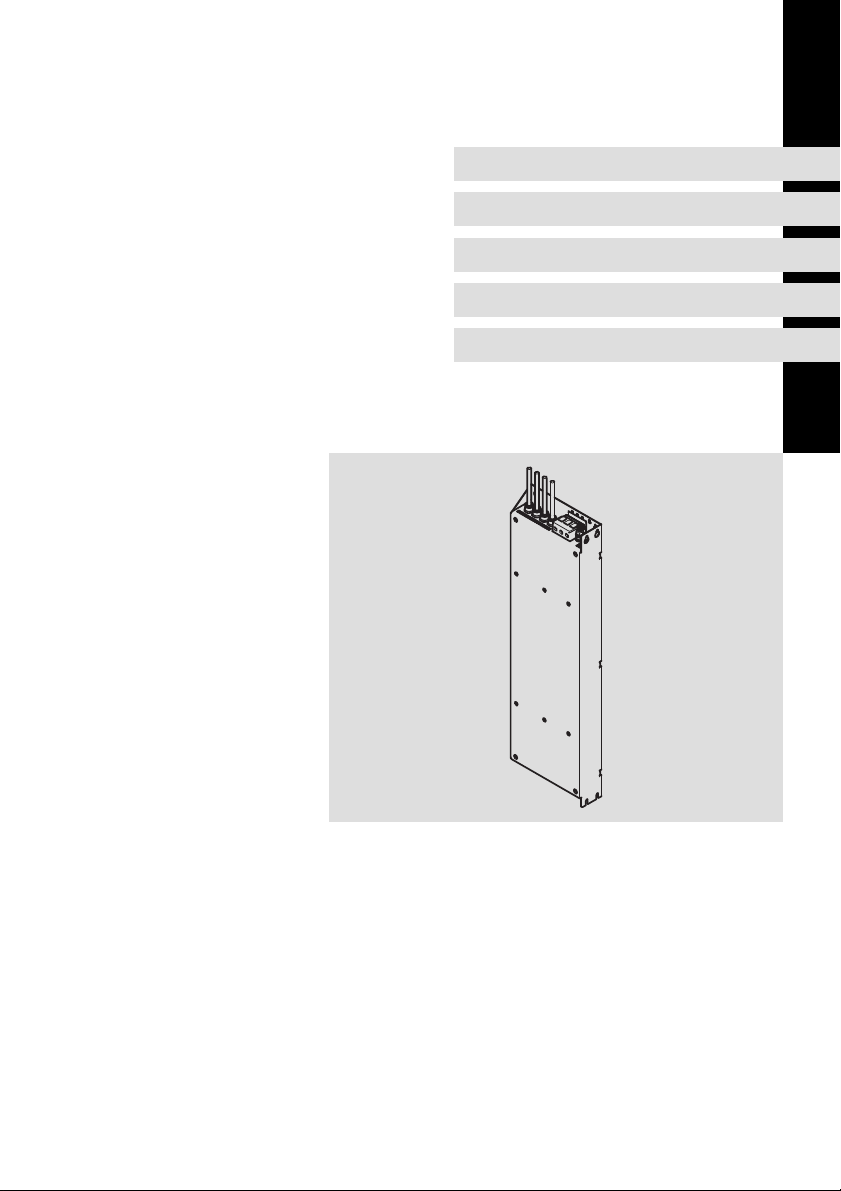
3.1 Lieferumfang
Pos. Beschreibung
Funk−Entstörfilter E94AZRSxxxx
Montageanleitung
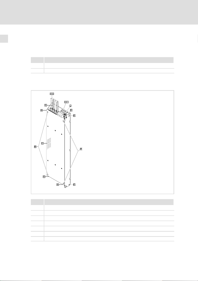
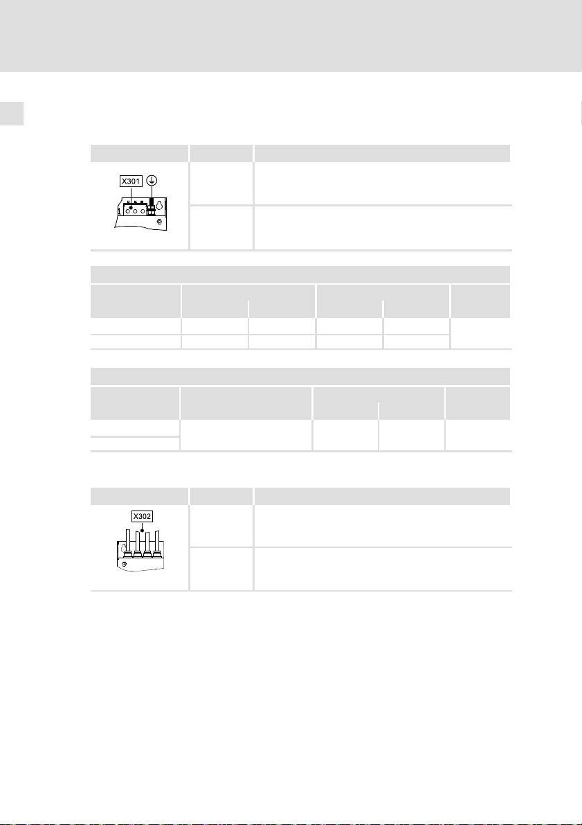
3.2 Übersicht
10
Pos. Beschreibung
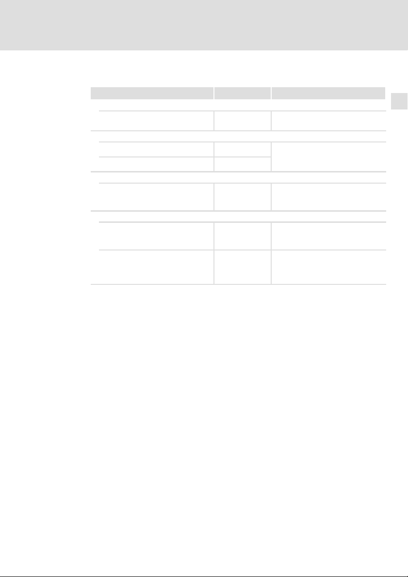
PE−Anschluss (für Ring− oder Gabelkabelschuh M8)
X301 Netzanschlussklemme L1 ... L3
X302 Anschlusskabel zum Antriebsregler 4−adrig
Befestigungsgewinde für Grundgerät
Typenschild
Befestigung Standardmontage (Unterbau−Montage)
Befestigung Montagevariante (Nebenbau−Montage)
SSP94FF601
EDK94AZRS6 DE/EN/FR/ES/IT 7.0
Page 11
3.3 Identifikation
L
Type:
Typenschlüssel E94 A Z R S xxx x
Produktreihe
Gerätegeneration
Zubehör
Typ Funk−Entstörfilter
für 9400 SingleDrive
Bemessungsstrom [A]
Spannungsklasse
4 = 230 ... 400/500 V
3.4 Einsatzbedingungen
Die Verwendung dieses Filters ist zulässig mit Geräten der Produktreihe 9400
und i700 ab der Typenschildbezeichnung:
Produktbeschreibung
Identifikation
3
SSP94NF002
E94ASxE032x
E94ASxE047x
E94ASxE059x
E94ASxE086x
E94ASxE104x
Zuordnung Filter ˘ Grundgerät
Typ Gerätegröße Typ Gerätegröße
E94AZRS0544 6
E94AZRS0954 7
EDK94AZRS6 DE/EN/FR/ES/IT 7.0
HW SW
1C
Funk−Entstörfilter Einzelachsregler
E94ASxE032x
E94ASxE047x
E94ASxE059x
E94ASxE086x
E94ASxE104x
1.51
6
7
11
Page 12

4
Technische Daten
Allgemeine Daten und Einsatzbedingungen
4 Technische Daten
4.1 Allgemeine Daten und Einsatzbedingungen
Konformität und Approbation
Approbation
UR
EAC TP TC 020/2011
EAC TP TC 004/2011
Angaben zu Netzen
Netzformen
Mit geerdetem Y−Punkt (TT−/TN−Netze)
Andere Netzformen Anweisungen über besondere Maßnahmen in der
UL508 Industrial Control Equipment, Underwriter Laborato-
(TR ZU 020/2011)
(TR ZU 004/2011)
ries (File−No. E219022) for USA and Canada
Elektromagnetische
Verträglichkeit von
technischen Erzeugnissen
Über die Sicherheit
von Niederspannungsausrüstung
Betrieb uneingeschränkt erlaubt
Dokumentation zum Grundgerät beachten!
Eurasische Konformität
TR ZU: Technische Regulierung der Zollunion
Eurasische Konformität
TR ZU: Technische Regulierung der Zollunion
12
Personenschutz und Geräteschutz
Schutzart
Erdableitstrom IEC/EN 61800−5−1 > 3.5 mA AC
Isolationsfestigkeit IEC/EN 61800−5−1
EN 60529 IP20
NEMA 250 Berührschutz nach
Typ 1
> 10 mA DC
< 2000 m Aufstellhöhe: Überspannungskategorie III
> 2000 m Aufstellhöhe: Überspannungskategorie II
Nicht im Anschlussbereich
der Klemmen
Bestimmungen und Sicherheitshinweise beachten!
EDK94AZRS6 DE/EN/FR/ES/IT 7.0
Page 13
Technische Daten
Allgemeine Daten und Einsatzbedingungen
Umweltbedingungen
Klima
Lagerung
Transport IEC/EN 60721−3−2 2K3 (−25 ... +70 °C)
Betrieb IEC/EN 60721−3−3 3K3 (−10 ... +55 °C)
Aufstellhöhe 0 ... 4000 m üNN
Verschmutzung EN 61800−5−1 Verschmutzungsgrad 2
Rüttelfestigkeit (9,81 m/s
Transport
Betrieb
Montagebedingungen
Einbauort Im Schaltschrank
Einbaulage Vertikal
Einbaufreiräume
Abmessungen
Gewichte
IEC/EN 60721−3−1 1K3 (−25 ... +60 °C)
Stromreduzierung von +45 ... +55 °C:
Gerätegröße 1 ... 7: 2.5 %/°C
Gerätegröße 8S ... 10: 1 %/°C
1000 ... 4000 m üNN: Stromreduzierung 5 %/1000 m
2
= 1 g)
IEC/EN 60721−3−2 2M2
EN 61800−2
Germanischer
Lloyd
IEC/EN 60068−2−6
2 ... 9 Hz: Amplitude 3.5 mm
10 ... 200 Hz: beschleunigungsfest bis 10 m/s
200 ... 500 Hz: beschleunigungsfest bis 15 m/s
5 ... 13.2 Hz: Amplitude ±1 mm
13.2 ... 100 Hz: beschleunigungsfest bis 0.7 g
10 ... 57 Hz: Amplitude 0.075 mm
57 ... 150 Hz: beschleunigungsfest bis 1 g
16
4
2
2
EDK94AZRS6 DE/EN/FR/ES/IT 7.0
13
Page 14
4
Technische Daten
Bemessungsdaten
4.2 Bemessungsdaten
Netz Spannung Spannungsbereich Frequenzbereich
3/PE AC 230 180 − 0 % ... 264 + 0 % 45 − 0 % ... 65 + 0 %
3/PE AC 400 320 − 0 % ... 440 + 0 % 45 − 0 % ... 65 + 0 %
3/PE AC 500 400 − 0 % ... 550 + 0 % 45 − 0 % ... 65 + 0 %
E94AZRS0544 230/400/500 50/60 54.0/54.0/54.0 40.5/40.5/40.5 3
E94AZRS0954 230/400/500 50/60 95.0/95.0/95.0 71.0/71.0/71.0 3
Temperatur im Schaltschrank
E94AZRS0544 50 ˘ ˘
E94AZRS0954 70 ˘ ˘
U
[V] U
LN
Spannung Frequenz Bemessungsstrom [A]
[V] [Hz] bis +45 °C bis +55 °C
Verlustleistung Induktivität Spannungsabfall
PV [W] L [mH] DU [V]
[V] f [Hz]
LN
Phasen-
zahl
14
EDK94AZRS6 DE/EN/FR/ES/IT 7.0
Page 15
4.3 Mechanische Daten
Technische Daten
Mechanische Daten
4
Alle Maße in Millimeter.
E94AZxS
...0544 201 610 670 170 650 41 24 12 500 ±10 6.5 13.0 9
...0954 261 713 790 230 760 48 27 17 550 ±10 9.0 16.5 13
EDK94AZRS6 DE/EN/FR/ES/IT 7.0
SSP94FF602
a b b1 c d d1 d2 e1 f g h Masse
[mm] [kg]
15
Page 16

5
Mechanische Installation
Wichtige Hinweise
5 Mechanische Installation
5.1 Wichtige Hinweise
ƒ Der Montageort muss den in den Technischen Daten genannten
Einsatzbedingungen immer entsprechen ( 12). Ggf. zusätzliche
Maßnahmen ergreifen.
ƒ Die Montageplatte des Schaltschranks muss folgende Eigenschaften
aufweisen:
– elektrisch leitfähig
– lackfrei
ƒ Die mechanischen Verbindungen müssen immer gewährleistet sein.
ƒ Eine ungehinderte Luftzirkulation zum Abführen der Wärme muss
gewährleistet sein.
Hinweis!
Das Filter kann in zwei Varianten montiert werden. Dadurch
ergeben sich unterschiedliche Einbaumaße.
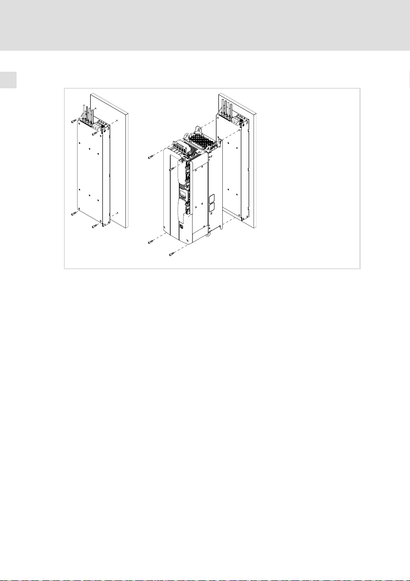
ƒ Standardmontage: Das Filter wird unter das Grundgerät
montiert.
ƒ Nebenbau−Montage: Bei geringer Schaltschranktiefe wird das
Filter um 90° gedreht, links neben das Grundgerät montiert.
16
EDK94AZRS6 DE/EN/FR/ES/IT 7.0
Page 17
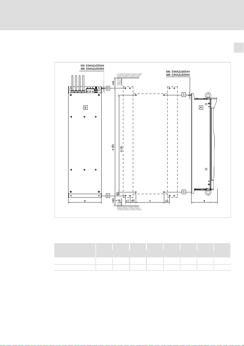
5.2 Standardmontage
5.2.1 Bohrplan
Mechanische Installation
Standardmontage
Bohrplan
5
Alle Maße in Millimeter.
Grundgerät ohne Unterbaufilter
Grundgerät mit Unterbaufilter
Lochraster für Grundgerät ohne Unterbaufilter
Lochraster für Grundgerät mit Unterbaufilter
E94AZxS0544 170 585 650 24 294 354
E94AZxS0954 230 685 760 27 370 430
EDK94AZRS6 DE/EN/FR/ES/IT 7.0
SSP94FF608
c d (A) d (B) d2 e (A) e (B)
[mm]
17
Page 18
5
5.2.2 Montageschritte
Mechanische Installation
Standardmontage
Montageschritte
So gehen Sie bei der Montage vor:
1. Bereiten Sie auf der Montageplatte M6−Gewindebohrungen vor und
bestücken Sie diese mit Schrauben und Unterlegscheiben.
– Vier M6−Kombischrauben oder M6−Innensechskantschrauben
(Festigkeitsklasse 8.8) mit Unterlegscheiben.
– Schrauben noch nicht ganz eindrehen.
2. Montieren Sie das Filter auf der vorbereiteten Montageplatte.
– Schrauben vorerst nur handfest anziehen.
3. Bestücken Sie die Gewindebohrungen für die Befestigung des
Grundgerätes auf dem Filter mit Schrauben und Unterlegscheiben.
– Vier Kombischrauben oder Innensechskantschrauben M6 x 20 mm mit
Unterlegscheiben.
– Schrauben noch nicht ganz eindrehen.
4. Montieren Sie das Grundgerät auf das Filter und ziehen Sie die Schrauben
fest an.
– Beachten Sie dabei die Hinweise in der Dokumentation zum
Grundgerät.
– Anzugsmoment: 8 Nm (70,8 lb−in)
5. Montieren Sie ggf. weitere Einheiten vor.
6. Richten Sie alle Einheiten miteinander aus.
7. Schrauben Sie alle Einheiten auf der Montageplatte fest.
– Anzugsmoment: 10 Nm (88,5 lb−in)
SSP94FF603
18
EDK94AZRS6 DE/EN/FR/ES/IT 7.0
Page 19
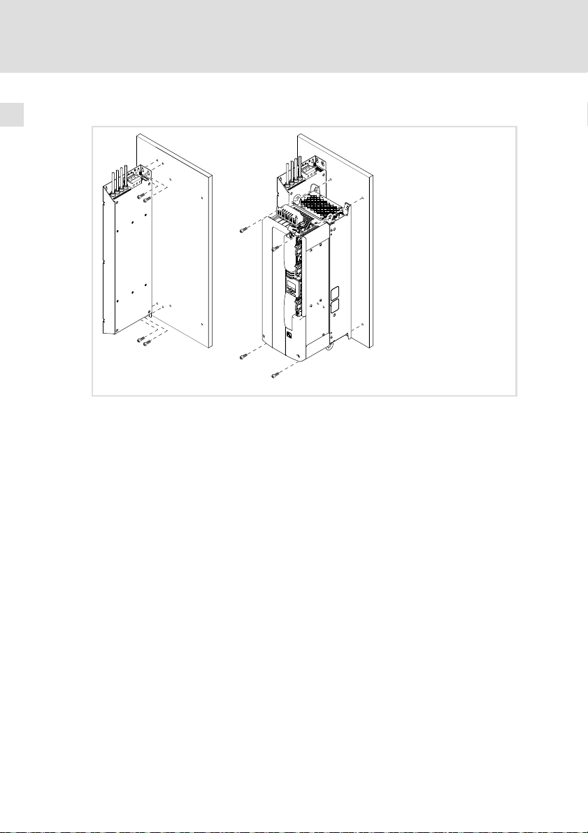
5.3 Montagevariante
5.3.1 Bohrplan
Mechanische Installation
Montagevariante
Bohrplan
5
Alle Maße in Millimeter.
Nebenbaufilter
Grundgerät
E94AZxS0544 201 170 30 30 585 650 24 294
E94AZxS0954 261 230 25 40 685 770 27 370
EDK94AZRS6 DE/EN/FR/ES/IT 7.0
SSP94FF609
a c c1 c2 d (A) d (B) d2 e
[mm]
19
Page 20
5
5.3.2 Montageschritte
Mechanische Installation
Montagevariante
Montageschritte
So gehen Sie bei der Montage vor:
1. Bereiten Sie auf der Montageplatte Gewindebohrungen vor:
– M6 für E94AZxS0544
– M8 für E94AZxS0954
2. Bestücken Sie diese mit Schrauben und Unterlegscheiben:
– Für Filter und Grundgerät je vier Kombischrauben oder
Innensechskantschrauben (Festigkeitsklasse 8.8) mit Unterlegscheiben.
– Schrauben noch nicht ganz eindrehen.
3. Montieren Sie das Filter auf der vorbereiteten Montageplatte.
– Schrauben vorerst nur handfest anziehen.
4. Montieren Sie das Grundgerät auf der vorbereiteten Montageplatte.
– Beachten Sie dabei die Hinweise in der Dokumentation zum
Grundgerät.
– Schrauben vorerst nur handfest anziehen.
5. Montieren Sie ggf. weitere Einheiten vor.
6. Richten Sie alle Einheiten miteinander aus.
7. Schrauben Sie alle Einheiten auf der Montageplatte fest.
Anzugsmoment:
– 10 Nm (88,5 lb−in) für E94AZxS0544
– 25 Nm (221 lb−in) für E94AZxS0954
SSP94FF604
20
EDK94AZRS6 DE/EN/FR/ES/IT 7.0
Page 21

6 Elektrische Installation
6.1 Wichtige Hinweise
ƒ Die Installation muss
– den in den Technischen Daten genannten Einsatzbedingungen immer
entsprechen ( 12).
– nach EN 60204−1 ausgeführt werden.
ƒ Bei der Auswahl des Leitungstyps beachten:
– Die verwendeten Leitungen müssen den geforderten Approbationen
am Einsatzort entsprechen (z. B. VDE, UL usw.).
– Absicherung und Leitungsquerschnitte gemäß den Vorgaben in der
Dokumentation zum Grundgerät bemessen.
Gefahr!
Gefährliche elektrische Spannung
Alle Leistungsanschlüsse führen bis zu 3 Minuten nach
Netz−Ausschalten gefährliche elektrische Spannung.
Mögliche Folgen:
ƒ Tod oder schwere Verletzungen beim Berühren der
Leistungsanschlüsse.
Schutzmaßnahmen:
ƒ Vor Arbeiten an den Leistungsanschlüssen Netz abschalten und
mindestens 3 Minuten warten.
ƒ Prüfen, ob alle Leistungsanschlüsse spannungsfrei sind.
Elektrische Installation
Wichtige Hinweise
6
EDK94AZRS6 DE/EN/FR/ES/IT 7.0
21
Page 22

6
Elektrische Installation
Wichtige Hinweise
Gefahr!
Gefährliche elektrische Spannung
Der Ableitstrom gegen Erde (PE) ist > 3.5 mA AC bzw. > 10 mA DC.
Mögliche Folgen:
ƒ Tod oder schwere Verletzungen beim Berühren des Gerätes im
Fehlerfall.
Schutzmaßnahmen:
Die in der EN 61800−5−1 geforderten Maßnahmen umsetzen.
Insbesondere:
ƒ Festinstallation
– PE−Anschluss normgerecht ausführen.
– PE−Leiter doppelt auflegen oder PE−Leiterquerschnitt ³ 10 mm
ƒ Anschluss mit einem Steckverbinder für industrielle
Anwendungen nach IEC 60309 (CEE):
– PE−Leiterquerschnitt ³ 2.5 mm2 als Teil eines mehradrigen
Versorgungskabels.
– Angemessene Zugentlastung vorsehen.
2
.
22
Stop!
Kein Geräteschutz gegen zu hohe Netzspannung
Der Netzeingang ist intern nicht abgesichert.
Mögliche Folgen:
ƒ Zerstörung des Gerätes bei zu hoher Netzspannung.
Schutzmaßnahmen:
ƒ Beachten Sie die maximal zulässige Netzspannung.
ƒ Sichern Sie das Gerät netzseitig fachgerecht gegen
Netzschwankungen und Spannungsspitzen ab.
EDK94AZRS6 DE/EN/FR/ES/IT 7.0
Page 23
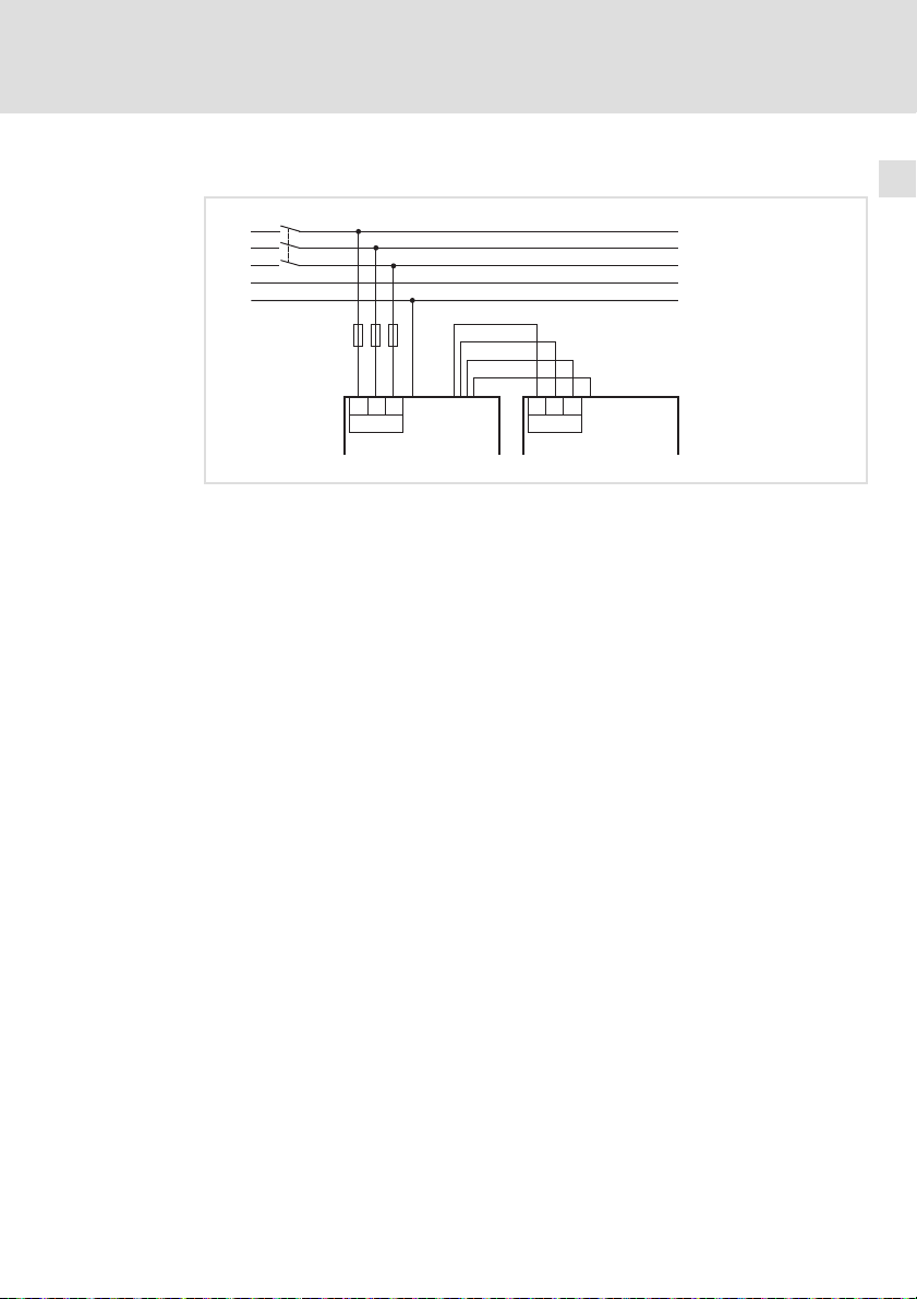
6.2 Anschlussplan
K1
L1
L2
L3
N
PE
Elektrische Installation
F1...F3
L3 L3
L1
X301 X100
E94AZxSxxxx E94ASxExxxxx
1 (BK)
2 (BK)
3 (BK)
PE (GN/YE)
+
X302
L1L2 L2
6
Anschlussplan
+
SSP94FF610
EDK94AZRS6 DE/EN/FR/ES/IT 7.0
23
Page 24
6
Elektrische Installation
Anschlussdaten
6.3 Anschlussdaten
Netz
Klemme X301 Beschriftung Beschreibung
SSP94FF606
Klemmendaten
E94AZxS0544 50 0
E94AZxS0954 95 000
PE−Anschlussdaten
E94AZxS0544
E94AZxS0954
Grundgerät
Leitung X302 Beschriftung Beschreibung
SSP94FF607
L1
L2
L3
Anschluss für den netzseitigen Schutzleiter mit Ringkabel-
max. Leiterquerschnitt Anzugsmoment
[mm2] [AWG] [Nm] [lb−in]
1
2
3
PE Ausgangsseitiger Schutzleiter (Litze mit Aderendhülse,
Anschluss der Netzphasen L1, L2, L3
schuh M8
10 88.5
14 124.0
Æ Anzugsmoment
[mm] [Nm] [lb−in]
M8
Filter−Ausgangsleiter (Litze mit Aderendhülsen, Farbe BK)
Farbe GN/YE)
12 106 SW 13
Inbus 5
6.4 Montageschritte
So schließen Sie das Filter an:
1. Filter−Ausgangsleitung (X302) an Klemme X100 am Grundgerät
anschließen.
2. Netzleitung an Klemme X301 anschließen.
3. Netzseitiger Schutzleiter mit Gabel− oder Ringkabelschuh an
Schutzleiter−Schraube montieren.
– Der PE−Anschluss muss nach EN 61800−5−1 ausgeführt werden.
24
EDK94AZRS6 DE/EN/FR/ES/IT 7.0
Page 25

Contents i
1 About this documentation 26. . . . . . . . . . . . . . . . . . . . . . . . . . . . . . . . . . . . . . . . . .
1.1 Validity information 26. . . . . . . . . . . . . . . . . . . . . . . . . . . . . . . . . . . . . . . .
1.2 Target group 26. . . . . . . . . . . . . . . . . . . . . . . . . . . . . . . . . . . . . . . . . . . . . .
1.3 Document history 26. . . . . . . . . . . . . . . . . . . . . . . . . . . . . . . . . . . . . . . . . .
1.4 Conventions used 27. . . . . . . . . . . . . . . . . . . . . . . . . . . . . . . . . . . . . . . . . . .
1.5 Notes used 28. . . . . . . . . . . . . . . . . . . . . . . . . . . . . . . . . . . . . . . . . . . . . . . .
2 Safety instructions 30. . . . . . . . . . . . . . . . . . . . . . . . . . . . . . . . . . . . . . . . . . . . . . . .
2.1 General safety information 30. . . . . . . . . . . . . . . . . . . . . . . . . . . . . . . . . . .
2.2 Residual hazards 31. . . . . . . . . . . . . . . . . . . . . . . . . . . . . . . . . . . . . . . . . . .
3 Product description 32. . . . . . . . . . . . . . . . . . . . . . . . . . . . . . . . . . . . . . . . . . . . . . .
3.1 Scope of supply 32. . . . . . . . . . . . . . . . . . . . . . . . . . . . . . . . . . . . . . . . . . . .
3.2 Overview 32. . . . . . . . . . . . . . . . . . . . . . . . . . . . . . . . . . . . . . . . . . . . . . . . . .
3.3 Identification 33. . . . . . . . . . . . . . . . . . . . . . . . . . . . . . . . . . . . . . . . . . . . . .
3.4 Operating conditions 33. . . . . . . . . . . . . . . . . . . . . . . . . . . . . . . . . . . . . . . .
4 Technical data 34. . . . . . . . . . . . . . . . . . . . . . . . . . . . . . . . . . . . . . . . . . . . . . . . . . . .
4.1 General data and operating conditions 34. . . . . . . . . . . . . . . . . . . . . . . .
4.2 Rated data 36. . . . . . . . . . . . . . . . . . . . . . . . . . . . . . . . . . . . . . . . . . . . . . . .
4.3 Mechanical data 37. . . . . . . . . . . . . . . . . . . . . . . . . . . . . . . . . . . . . . . . . .
5 Mechanical installation 38. . . . . . . . . . . . . . . . . . . . . . . . . . . . . . . . . . . . . . . . . . . .
5.1 Important notes 38. . . . . . . . . . . . . . . . . . . . . . . . . . . . . . . . . . . . . . . . . . . .
5.2 Standard mounting 39. . . . . . . . . . . . . . . . . . . . . . . . . . . . . . . . . . . . . . . . .
5.2.1 Drilling pattern 39. . . . . . . . . . . . . . . . . . . . . . . . . . . . . . . . . . .
5.2.2 Mounting steps 40. . . . . . . . . . . . . . . . . . . . . . . . . . . . . . . . . . .
5.3 Mounting variant 41. . . . . . . . . . . . . . . . . . . . . . . . . . . . . . . . . . . . . . . . . . .
5.3.1 Drilling pattern 41. . . . . . . . . . . . . . . . . . . . . . . . . . . . . . . . . . .
5.3.2 Mounting steps 42. . . . . . . . . . . . . . . . . . . . . . . . . . . . . . . . . . .
6 Electrical installation 43. . . . . . . . . . . . . . . . . . . . . . . . . . . . . . . . . . . . . . . . . . . . . .
6.1 Important notes 43. . . . . . . . . . . . . . . . . . . . . . . . . . . . . . . . . . . . . . . . . . . .
6.2 Connection plan 45. . . . . . . . . . . . . . . . . . . . . . . . . . . . . . . . . . . . . . . . . . . .
6.3 Connection data 46. . . . . . . . . . . . . . . . . . . . . . . . . . . . . . . . . . . . . . . . . . . .
6.4 Mounting steps 46. . . . . . . . . . . . . . . . . . . . . . . . . . . . . . . . . . . . . . . . . . . .
EDK94AZRS6 DE/EN/FR/ES/IT 7.0
25
Page 26

1
About this documentation
Validity information
1 About this documentation
0Fig. 0Tab. 0
1.1 Validity information
These instructions are valid for
ƒ RFI filter E94AZRS0544
ƒ RFI filter E94AZRS0954
1.2 Target group
This documentation is directed at qualified skilled personnel according to
IEC 60364.
Qualified skilled personnel are persons who have the required qualifications to
carry out all activities involved in installing, mounting, commissioning, and
operating the product.
Tip!
Information and tools concerning the Lenze products can be found
1.3 Document history
in the download area under
www.lenze.com
Material number Version Description
.OdJ 7.0 09/2014 TD15 UL notes in French for Canada
13429260 6.0 04/2013 TD06 Revision
13348755 5.0 09/2010 TD29 New edition due to company reorganisation,
13237063 4.0 02/2008 TD29 Revision
13218947 3.0 09/2007 TD29 Revision
13204554 2.0 04/2007 TD29 Revision, in 5 languages
13169226 1.0 11/2006 TD29 First edition
EAC Conformity
General corrections
layout adaptation, and revision
26
EDK94AZRS6 DE/EN/FR/ES/IT 7.0
Page 27
1.4 Conventions used
Type of information Identification Examples/notes
Spelling of numbers
Decimal separator Point In general, the decimal point is used.
Warnings
UL warnings
UR warnings
Text
Program name » « PC software
Icons
Page reference Reference to another page with
Documentation reference Reference to another documentation
About this documentation
Conventions used
For instance: 1234.56
Given in English and French
For example: »Engineer«, »Global
Drive Control« (GDC)
additional information
For instance: 16 = see page 16
with additional information
For example: EDKxxx = see
documentation EDKxxx
1
EDK94AZRS6 DE/EN/FR/ES/IT 7.0
27
Page 28

1
About this documentation
Notes used
1.5 Notes used
The following pictographs and signal words are used in this documentation to
indicate dangers and important information:
Safety instructions
Structure of safety instructions:
Danger!
Pictograph and signal word Meaning
Danger!
Danger!
Stop!
Application notes
(characterises the type and severity of danger)
Note
(describes the danger and gives information about how to prevent
dangerous situations)
Danger of personal injury through dangerous electrical
voltage.
Reference to an imminent danger that may result in
death or serious personal injury if the corresponding
measures are not taken.
Danger of personal injury through a general source of
danger.
Reference to an imminent danger that may result in
death or serious personal injury if the corresponding
measures are not taken.
Danger of property damage.
Reference to a possible danger that may result in
property damage if the corresponding measures are not
taken.
28
Pictograph and signal word Meaning
Note!
Tip!
Important note to ensure troublefree operation
Useful tip for simple handling
Reference to another documentation
EDK94AZRS6 DE/EN/FR/ES/IT 7.0
Page 29

About this documentation
Special safety instructions and application notes
Pictograph and signal word Meaning
1
Notes used
Warnings!
Warnings!
Safety note or application note for the operation
according to UL or CSA requirements.
The measures are required to meet the requirements
according to UL or CSA.
EDK94AZRS6 DE/EN/FR/ES/IT 7.0
29
Page 30

2
Safety instructions
General safety information
2 Safety instructions
2.1 General safety information
Danger!
Disregarding the following basic safety measures may lead to
severe personal injury and damage to material assets!
ƒ Lenze drive and automation components ...
... must only be used for the intended purpose.
... must never be operated if damaged.
... must never be subjected to technical modifications.
... must never be operated unless completely assembled.
... must never be operated without the covers/guards.
... can − depending on their degree of protection − have live, movable or
rotating parts during or after operation. Surfaces can be hot.
ƒ All specifications of the corresponding enclosed documentation must be
observed.
This is vital for a safe and trouble−free operation and for achieving the
specified product features.
The procedural notes and circuit details provided in this document are
proposals which the user must check for suitability for his application. The
manufacturer does not accept any liability for the suitability of the specified
procedures and circuit proposals.
ƒ Only qualified skilled personnel are permitted to work with or on Lenze
drive and automation components.
According to IEC 60364 or CENELEC HD 384, these are persons ...
... who are familiar with the installation, assembly, commissioning and
operation of the product,
... possess the appropriate qualifications for their work,
... and are acquainted with and can apply all the accident prevent
regulations, directives and laws applicable at the place of use.
30
EDK94AZRS6 DE/EN/FR/ES/IT 7.0
Page 31

2.2 Residual hazards
Danger!
Dangerous electrical voltage
All power terminals remain live for up to three minutes after mains
disconnection.
Possible consequences:
ƒ Death or severe injuries when touching the power terminals.
Protective measures:
ƒ Switch off the power supply and wait for at least three minutes
before working on the power terminals.
ƒ Make sure that all power terminals are deenergised.
Warnings!
Conditions of Acceptability:
ƒ The products covered by this report are only intended for use
with Power Conversion Equipment (inverters).
ƒ Consideration shall be given to the field wiring leads. No strain
relief test was performed on the leads.
ƒ The devices in this report are only evaluated for factory wiring
use.
ƒ Temperature tests were performed with hook mounted drive.
ƒ Reactor model E94AZR0544 shall be installed with input wiring
of 4 AWG minimum. Reactor model E94AZR0954 shall be
installed with input wiring of 1/0 AWG minimum.
Safety instructions
Residual hazards
2
EDK94AZRS6 DE/EN/FR/ES/IT 7.0
31
Page 32

3
Product description
Scope of supply
3 Product description
3.1 Scope of supply
Pos. Description
RFI filter E94AZRSxxxx
Mounting Instructions
3.2 Overview
32
Pos. Description
PE connection (for ring or fork−type cable lug M8)
X301 Mains terminal L1 ... L3
X302 Connection cable to controller, four−core
Fastening thread for standard device
Nameplate
Fixings for standard mounting (footprint mounting)
Fixings for mounting variant (side−by−side mounting)
SSP94FF601
EDK94AZRS6 DE/EN/FR/ES/IT 7.0
Page 33

3.3 Identification
L
Type:
Type code E94 A Z R S xxx x
Product range
Version
Accessories
Type: RFI filter
For 9400 SingleDrive
Rated current [A]
Voltage class
4 = 230 ... 400/500 V
3.4 Operating conditions
The use of this filter is permissible with devices of the 9400 and i700 product
ranges starting from nameplate data:
Product description
Identification
3
SSP94NF002
E94ASxE032x
E94ASxE047x
E94ASxE059x
E94ASxE086x
E94ASxE104x
Assignment of filters to standard devices
Type Device size Type Device size
E94AZRS0544 6
E94AZRS0954 7
EDK94AZRS6 DE/EN/FR/ES/IT 7.0
HW SW
1C
RFI filter Single−axis controller
E94ASxE032x
E94ASxE047x
E94ASxE059x
E94ASxE086x
E94ASxE104x
1.51
6
7
33
Page 34

4
Technical data
General data and operating conditions
4 Technical data
4.1 General data and operating conditions
Conformity and approval
Approval
UR
EAC TP TC 020/2011
EAC TP TC 004/2011
Mains data
Mains types
With grounded neutral (TT/TN systems)
Other mains types Observe instructions for special measures in the
UL508 Industrial Control Equipment, Underwriter
(TR CU 020/2011)
(TR CU 004/2011)
Laboratories (File−No. E219022) for USA and Canada
Electromagnetic
compatibility of
technical means
On safety of low
voltage equipment
Operation permitted without restrictions
documentation for the basic device!
Protection of persons and equipment
Enclosure
Earth leakage current IEC/EN 61800−5−1 > 3.5 mA AC
Insulation resistance IEC/EN 61800−5−1
EN 60529
NEMA 250 Protection against
IP20
contact to type 1
> 10 mA DC
< 2000 m site altitude: overvoltage category III
> 2000 m site altitude: overvoltage category II
Eurasian Conformity
TR CU: Technical Regulation
of Customs Union
Eurasian Conformity
TR CU: Technical Regulation
of Customs Union
Not in the wire range of the
terminals
Observe regulations and
safety instructions!
34
EDK94AZRS6 DE/EN/FR/ES/IT 7.0
Page 35

Technical data
General data and operating conditions
Environmental conditions
Climate
Storage
Transport IEC/EN 60721−3−2 2K3 (−25 ... +70 °C)
Operation IEC/EN 60721−3−3 3K3 (−10 ... +55 °C)
Site altitude 0 ... 4000 m amsl
Pollution EN 61800−5−1 Degree of pollution 2
Vibration resistance (9.81 m/s
Transport
Operation
IEC/EN 60721−3−1 1K3 (−25 ... +60 °C)
Current derating at +45 ... +55 °C:
Device size 1 ... 7: 2.5 %/°C
Device size 8S ... 10: 1 %/°C
1000 ... 4000 m amsl: current derating of
5 %/1000 m
2
= 1 g)
IEC/EN 60721−3−2 2M2
EN 61800−2
Germanischer
Lloyd
IEC/EN 60068−2−6
2 ... 9 Hz: amplitude 3.5 mm
10 ... 200 Hz: acceleration resistant up to 10 m/s
200 ... 500 Hz: acceleration resistant up to 15 m/s
5 ... 13.2 Hz: amplitude ±1 mm
13.2 ... 100 Hz: acceleration resistant up to 0.7 g
10 ... 57 Hz: amplitude 0.075 mm
57 ... 150 Hz: acceleration resistant up to 1 g
4
2
2
Mounting conditions
Mounting place In the control cabinet
Mounting position Vertical
Free spaces
Dimensions
Weights
EDK94AZRS6 DE/EN/FR/ES/IT 7.0
38
35
Page 36

4
Technical data
Rated data
4.2 Rated data
Mains Voltage Voltage range Frequency range
3/PE AC 230 180 − 0 % ... 264 + 0 % 45 − 0 % ... 65 + 0 %
3/PE AC 400 320 − 0 % ... 440 + 0 % 45 − 0 % ... 65 + 0 %
3/PE AC 500 400 − 0 % ... 550 + 0 % 45 − 0 % ... 65 + 0 %
E94AZRS0544 230/400/500 50/60 54.0/54.0/54.0 40.5/40.5/40.5 3
E94AZRS0954 230/400/500 50/60 95.0/95.0/95.0 71.0/71.0/71.0 3
Temperature in the control cabinet
E94AZRS0544 50 ˘ ˘
E94AZRS0954 70 ˘ ˘
U
[V] U
Lrated
Voltage Frequency Rated current [A]
[V] [Hz] up to +45 °C up to +55 °C
Power loss Inductance Voltage drop
P
[W] L [mH] DU [V]
loss
[V] f [Hz]
Lrated
Number of
phases
36
EDK94AZRS6 DE/EN/FR/ES/IT 7.0
Page 37

4.3 Mechanical data
Technical data
Mechanical data
4
All dimensions in millimetres.
E94AZxS
...0544 201 610 670 170 650 41 24 12 500 ±10 6.5 13.0 9
...0954 261 713 790 230 760 48 27 17 550 ±10 9.0 16.5 13
EDK94AZRS6 DE/EN/FR/ES/IT 7.0
SSP94FF602
a b b1 c d d1 d2 e1 f g h Mass
[mm] [kg]
37
Page 38

5
Mechanical installation
Important notes
5 Mechanical installation
5.1 Important notes
ƒ The mounting location must always comply with the operating conditions
specified in the technical data ( 34). Take additional measures if
necessary.
ƒ The mounting plate of the control cabinet must have the following
properties:
– electrically conductive
– free of lacquer
ƒ The mechanical connections must always be ensured.
ƒ A free air circulation must be ensured for dissipating the heat.
Note!
The filter can be mounted in two ways. From this result different
mounting dimensions.
ƒ Standard mounting: The filter is mounted underneath the
standard device.
ƒ Side−by−side mounting: In case of a low depth of the control
cabinet, the filter is rotated by 90° and mounted to the left side
of the standard device.
38
EDK94AZRS6 DE/EN/FR/ES/IT 7.0
Page 39

5.2 Standard mounting
5.2.1 Drilling pattern
Mechanical installation
Standard mounting
Drilling pattern
5
All dimensions in millimetres.
Standard device without footprint filter
Standard device with footprint filter
Hole pattern for standard device without footprint filter
Hole pattern for standard device with footprint filter
E94AZxS0544 170 585 650 24 294 354
E94AZxS0954 230 685 760 27 370 430
EDK94AZRS6 DE/EN/FR/ES/IT 7.0
SSP94FF608
c d (A) d (B) d2 e (A) e (B)
[mm]
39
Page 40

5
5.2.2 Mounting steps
Mechanical installation
Standard mounting
Mounting steps
Proceed as follows for the installation:
1. Drill M6 threaded holes in the mounting plate and attach screws and
washers.
– Four M6 screw and washer assemblies or M6 hexagon socket screws
(property class 8.8) with washers.
– Attach the screws loosely first.
2. Attach the filter to the prepared mounting plate.
– Tighten the screws hand−tight.
3. Attach screws and washers to the threaded holes for fastening the
standard device on the filter.
– Four screw and washer assemblies or hexagon socket screws
M6 x 20 mm with washers.
– Attach the screws loosely first.
4. Attach the standard device to the filter and tighten the screws fully.
– Observe the notes given in the documentation for the standard device.
– Tightening torque: 8 Nm (70.8 lb−in)
5. If necessary, pre−assemble further units.
6. Align all units.
7. Screw all units tightly to the mounting plate.
– Tightening torque: 10 Nm (88.5 lb−in)
SSP94FF603
40
EDK94AZRS6 DE/EN/FR/ES/IT 7.0
Page 41

5.3 Mounting variant
5.3.1 Drilling pattern
Mechanical installation
Mounting variant
Drilling pattern
5
All dimensions in millimetres.
Side−by−side filter
Standard device
E94AZxS0544 201 170 30 30 585 650 24 294
E94AZxS0954 261 230 25 40 685 770 27 370
EDK94AZRS6 DE/EN/FR/ES/IT 7.0
SSP94FF609
a c c1 c2 d (A) d (B) d2 e
[mm]
41
Page 42

5
5.3.2 Mounting steps
Mechanical installation
Mounting variant
Mounting steps
How to proceed during the mounting process:
1. Prepare threaded holes on the mounting plate:
– M6 for E94AZxS0544
– M8 for E94AZxS0954
2. Assemble the threaded holes with screws and washers:
– For filters and the standard device, use four screw and washer
assemblies or hexagon socket screws, respectively (property class 8.8),
with washers.
– Do not turn in the screws completely yet.
3. Mount the filter on the prepared mounting plate.
– For now, just tighten the screws in a hand−tight fashion.
4. Mount the standard device on the prepared mounting plate.
– Observe the notes in the documentation for the standard device.
– For now, just tighten the screws in a hand−tight fashion.
5. If required, pre−assemble further units.
6. Align all units to each other.
7. Tighten all units on the mounting plate.
Tightening torque:
– 10 Nm (88.5 lb−in) for E94AZxS0544
– 25 Nm (221 lb−in) for E94AZxS0954
SSP94FF604
42
EDK94AZRS6 DE/EN/FR/ES/IT 7.0
Page 43

6 Electrical installation
6.1 Important notes
ƒ Installation must
– always be in accordance with the operating conditions specified in the
Technical data ( 34).
– be carried out to EN 60204−1.
ƒ Please observe the following when selecting the cable type:
– The cables used must comply with the approvals required for the
application (e. g. VDE, UL etc.).
– Fuses and cable cross−sections must be dimensioned in accordance with
the specifications in the documentation for the basic device.
Danger!
Dangerous electrical voltage
All power terminals remain live for up to three minutes after mains
disconnection.
Possible consequences:
ƒ Death or severe injuries when touching the power terminals.
Protective measures:
ƒ Switch off the power supply and wait for at least three minutes
before working on the power terminals.
ƒ Make sure that all power terminals are deenergised.
Electrical installation
Important notes
6
EDK94AZRS6 DE/EN/FR/ES/IT 7.0
43
Page 44

6
Electrical installation
Important notes
Danger!
Hazardous electrical voltage
The leakage current to earth (PE) is > 3.5 mA AC or > 10 mA DC.
Possible consequences:
ƒ Death or severe injuries when touching the device in the event of
an error.
Protective measures:
Implement the measures required in EN 61800−5−1. Especially:
ƒ Fixed installation
– Implement PE connection in compliance with standards.
– Connect PE conductor twice or PE conductor cross−section
³ 10 mm
ƒ Connection with a connector for industrial applications according
to IEC 60309 (CEE):
– PE conductor cross−section ³ 2.5 mm2 as part of a multi−core
supply cable.
– Provide for suitable strain relief.
2
.
44
Stop!
No device protection if the mains voltage is too high
The mains input is not internally fused.
Possible consequences:
ƒ Destruction of the device if the mains voltage is too high.
Protective measures:
ƒ Observe the maximally permissible mains voltage.
ƒ Fuse the device correctly on the supply side against mains
fluctuations and voltage peaks.
EDK94AZRS6 DE/EN/FR/ES/IT 7.0
Page 45

6.2 Connection plan
K1
L1
L2
L3
N
PE
F1...F3
Electrical installation
1 (BK)
2 (BK)
3 (BK)
PE (GN/YE)
L3 L3
L1
+
X301 X100
E94AZxSxxxx E94ASxExxxxx
X302
L1L2 L2
+
6
Connection plan
SSP94FF610
EDK94AZRS6 DE/EN/FR/ES/IT 7.0
45
Page 46

6
Electrical installation
Connection data
6.3 Connection data
Mains
Terminal X301 Labelling Description
SSP94FF606
Terminal data
E94AZxS0544 50 0
E94AZxS0954 95 000
PE connection data
E94AZxS0544
E94AZxS0954
Standard device
Cable X302 Labelling Description
SSP94FF607
L1
L2
L3
Connection for the supply−side PE conductor with ring cable
Max. conductor cross−section Tightening torque
[mm2] [AWG] [Nm] [lb−in]
1
2
3
PE Output−side PE conductor (lead with wire end ferrule,
Connection of the mains phases L1, L2, L3
lug M8
10 88.5
14 124.0
Æ Starting torque
[mm] [Nm] [lb−in]
M8
Filter output conductor (lead with wire end ferrules, colour
BK)
colour GN/YE)
12 106 SW 13
Hexagon
socket 5
6.4 Mounting steps
Proceed as follows to connect the filter:
1. Connect the filter output cable (X302) to terminal X100 of the standard
device.
2. Connect the mains cable to terminal X301.
3. Attach the supply−side PE conductor to the PE conductor screw using a
ring or fork−type cable lug.
– The PE connection must comply with EN 61800−5−1.
46
EDK94AZRS6 DE/EN/FR/ES/IT 7.0
Page 47

Sommaire i
1 Présentation du document 48. . . . . . . . . . . . . . . . . . . . . . . . . . . . . . . . . . . . . . . . .
1.1 Validité 48. . . . . . . . . . . . . . . . . . . . . . . . . . . . . . . . . . . . . . . . . . . . . . . . . . .
1.2 Public visé 48. . . . . . . . . . . . . . . . . . . . . . . . . . . . . . . . . . . . . . . . . . . . . . . . .
1.3 Historique du document 48. . . . . . . . . . . . . . . . . . . . . . . . . . . . . . . . . . . . .
1.4 Conventions utilisées 49. . . . . . . . . . . . . . . . . . . . . . . . . . . . . . . . . . . . . . .
1.5 Consignes utilisées 50. . . . . . . . . . . . . . . . . . . . . . . . . . . . . . . . . . . . . . . . .
2 Consignes de sécurité 52. . . . . . . . . . . . . . . . . . . . . . . . . . . . . . . . . . . . . . . . . . . . . .
2.1 Consignes générales de sécurité 52. . . . . . . . . . . . . . . . . . . . . . . . . . . . . . .
2.2 Dangers résiduels 53. . . . . . . . . . . . . . . . . . . . . . . . . . . . . . . . . . . . . . . . . .
3 Description du produit 54. . . . . . . . . . . . . . . . . . . . . . . . . . . . . . . . . . . . . . . . . . . . .
3.1 Equipement livré 54. . . . . . . . . . . . . . . . . . . . . . . . . . . . . . . . . . . . . . . . . . .
3.2 Présentation générale 54. . . . . . . . . . . . . . . . . . . . . . . . . . . . . . . . . . . . . . .
3.3 Identification 55. . . . . . . . . . . . . . . . . . . . . . . . . . . . . . . . . . . . . . . . . . . . . .
3.4 Conditions d’utilisation 55. . . . . . . . . . . . . . . . . . . . . . . . . . . . . . . . . . . . . .
4 Spécifications techniques 56. . . . . . . . . . . . . . . . . . . . . . . . . . . . . . . . . . . . . . . . . .
4.1 Caractéristiques générales et conditions d’utilisation 56. . . . . . . . . . . .
4.2 Caractéristiques assignées 58. . . . . . . . . . . . . . . . . . . . . . . . . . . . . . . . . . .
4.3 Caractéristiques mécaniques 59. . . . . . . . . . . . . . . . . . . . . . . . . . . . . . . .
5 Installation mécanique 60. . . . . . . . . . . . . . . . . . . . . . . . . . . . . . . . . . . . . . . . . . . .
5.1 Remarques importantes 60. . . . . . . . . . . . . . . . . . . . . . . . . . . . . . . . . . . . .
5.2 Montage standard 61. . . . . . . . . . . . . . . . . . . . . . . . . . . . . . . . . . . . . . . . . .
5.2.1 Plan de perçage 61. . . . . . . . . . . . . . . . . . . . . . . . . . . . . . . . . . .
5.2.2 Opérations de montage 62. . . . . . . . . . . . . . . . . . . . . . . . . . . .
5.3 Variante de montage 63. . . . . . . . . . . . . . . . . . . . . . . . . . . . . . . . . . . . . . .
5.3.1 Plan de perçage 63. . . . . . . . . . . . . . . . . . . . . . . . . . . . . . . . . . .
5.3.2 Opérations de montage 64. . . . . . . . . . . . . . . . . . . . . . . . . . . .
6 Installation électrique 65. . . . . . . . . . . . . . . . . . . . . . . . . . . . . . . . . . . . . . . . . . . . .
6.1 Remarques importantes 65. . . . . . . . . . . . . . . . . . . . . . . . . . . . . . . . . . . . .
6.2 Schéma de câblage 67. . . . . . . . . . . . . . . . . . . . . . . . . . . . . . . . . . . . . . . . .
6.3 Données de raccordement 68. . . . . . . . . . . . . . . . . . . . . . . . . . . . . . . . . . .
6.4 Opérations de montage 69. . . . . . . . . . . . . . . . . . . . . . . . . . . . . . . . . . . . . .
EDK94AZRS6 DE/EN/FR/ES/IT 7.0
47
Page 48

1
Présentation du document
Validité
1 Présentation du document
0Fig. 0Tab. 0
1.1 Validité
Le présent document s’applique au produits suivants :
ƒ Filtre antiparasite E94AZRS0544
ƒ Filtre antiparasite E94AZRS0954
1.2 Public visé
Cette documentation s’adresse à un personnel qualifié et habilité
conformément à la norme CEI 60364.
On entend par "personnel qualifié et habilité" des personnes compétentes en
matière d’installation, de montage, de mise en service et de fonctionnement du
produit et possédant les qualifications correspondant à leurs activités.
Conseil !
Toutes les informations relatives aux produits Lenze peuvent être
1.3 Historique du document
téléchargées sur notre site à l’adresse suivante :
www.Lenze.com
Numéro de document Version Description
.OdJ 7.0 09/2014 TD15 Consignes UL en français pour le Canada
13429260 6.0 04/2013 TD06 Édition revue
13348755 5.0 09/2010 TD29 Nouvelle édition en raison de la nouvelle
13237063 4.0 02/2008 TD29 Édition revue
13218947 3.0 09/2007 TD29 Édition revue
13204554 2.0 04/2007 TD29 Édition revue, en 5 langues
13169226 1.0 11/2006 TD29 Première édition
Conformité EAC
Corrections générales
organisation de l’entreprise ; adaptation de la
mise en page et texte revu
48
EDK94AZRS6 DE/EN/FR/ES/IT 7.0
Page 49

1.4 Conventions utilisées
Type d’information Aperçu Exemples/remarques
Représentation des chiffres
Séparateur décimal Point Le point décimal est généralement
Consignes préventives
Consignes préventives UL
Consignes préventives UR
Mise en évidence de textes spéciaux
Nom de programme » « Logiciel pour PC
Pictogrammes
Renvoi à la page Renvoi à une autre page contenant
Renvoi à une documentation Renvoi à une autre documentation
Présentation du document
Conventions utilisées
utilisé.
Exemple : 1234.56
En anglais et en français
Exemple : »Engineer«, »Global Drive
Control« (GDC)
des informations supplémentaires.
Par exemple : 16 = voir page 16
contenant des informations
supplémentaires.
Par exemple : EDKxxx = voir la
documentation EDKxxx
1
EDK94AZRS6 DE/EN/FR/ES/IT 7.0
49
Page 50

1
Présentation du document
Consignes utilisées
1.5 Consignes utilisées
Pour indiquer des risques et des informations importantes, la présente
documentation utilise les mots et pictogrammes suivants :
Consignes de sécurité
Présentation des consignes de sécurité
Danger !
(Le pictogramme indique le type de risque.)
Explication
(L’explication décrit le risque et les moyens de l’éviter.)
Pictogramme et mot associé Explication
Danger !
Danger !
Stop !
Consignes d’utilisation
Situation dangereuse pour les personnes en raison
d’une tension électrique élevée
Indication d’un danger imminent qui peut avoir pour
conséquences des blessures mortelles ou très graves en
cas de non−respect des consignes de sécurité
correspondantes
Situation dangereuse pour les personnes en raison d’un
danger d’ordre général
Indication d’un danger imminent qui peut avoir pour
conséquences des blessures mortelles ou très graves en
cas de non−respect des consignes de sécurité
correspondantes
Risques de dégâts matériels
Indication d’un risque potentiel qui peut avoir pour
conséquences des dégâts matériels en cas de
non−respect des consignes de sécurité correspondantes
50
Pictogramme et mot associé Explication
Remarque
importante !
Conseil !
Remarque importante pour assurer un fonctionnement
correct
Conseil utile pour faciliter la mise en uvre
Renvoi à une autre documentation
EDK94AZRS6 DE/EN/FR/ES/IT 7.0
Page 51

Présentation du document
Consignes de sécurité et d’utilisation spéciales
Pictogramme et mot associé Description
1
Consignes utilisées
Avertissements !
Avertissements !
Consigne de sécurité ou d’utilisation pour le
fonctionnement selon les normes UL ou CSA.
Les mesures sont requises pour répondre aux exigences
des normes UL ou CSA.
EDK94AZRS6 DE/EN/FR/ES/IT 7.0
51
Page 52

2
Consignes de sécurité
Consignes générales de sécurité
2 Consignes de sécurité
2.1 Consignes générales de sécurité
Danger !
Le non−respect des consignes fondamentales de sécurité suivantes
peut entraîner des blessures et des dommages matériels graves.
ƒ Les composants d’entraînement et d’automatisation Lenze ...
... doivent exclusivement être utilisés conformément à leur fonction.
... ne doivent jamais être mis en service si des dommages sont décelés.
... ne doivent jamais être modifiés d’un point de vue technique.
... ne doivent jamais être mis en service s’ils ne sont pas montés
intégralement.
... ne doivent jamais être mis en service sans le capot obligatoire.
... peuvent − selon l’indice de protection − contenir des pièces sous tension, en
mouvement ou en rotation. Les surfaces peuvent être brûlantes.
ƒ Respecter les consignes et les indications contenues dans la
documentation concernée.
Il s’agit de la condition préalable pour garantir un fonctionnement sûr et
fiable et pour obtenir les caractéristiques du produit indiquées.
Les procédures à suivre et les plans de raccordement fournis constituent des
recommandations dont l’adéquation avec l’application concernée doit être
vérifiée. Lenze n’assumera aucune responsabilité pour les dommages liés à
un problème d’adéquation des procédures et plans de raccordements
indiqués.
ƒ Les travaux réalisés avec et au niveau des composants d’entraînement et
d’automatisation Lenze ne doivent être exécutés que par un personnel
qualifié et habilité.
Selon les normes CEI 60364 ou CENELEC HD 384, ces personnes doivent ...
... connaître parfaitement l’installation, le montage, la mise en service et le
fonctionnement du produit.
... posséder les qualifications appropriées pour l’exercice de leur activité.
... connaître toutes les prescriptions pour la prévention d’accidents,
directives et lois applicables sur le lieu d’utilisation et être en mesure de les
appliquer.
52
EDK94AZRS6 DE/EN/FR/ES/IT 7.0
Page 53

2.2 Dangers résiduels
Danger !
Tension électrique dangereuse
Les raccordements de puissance sont encore sous tension jusqu’à 3
minutes après la coupure réseau.
Risques encourus :
ƒ Mort ou blessures graves en cas de contact accidentel avec les
raccordements de puissance.
Mesures de protection :
ƒ Avant toute intervention au niveau des raccordements de
puissance, couper l’alimentation et attendre au moins 3 minutes.
ƒ S’assurer que tous les raccordements de puissance sont hors
tension.
Consignes de sécurité
Dangers résiduels
2
Avertissements !
Conditions d’acceptabilité :
ƒ Les produits concernés par ce rapport sont destinés
exclusivement à être utilisés avec des convertisseurs de
puissance (variateurs ou power conversion equipment).
ƒ Une attention particulière doit être apportée au câblage à pied
d’oeuvre. Aucun test de décharge de traction n’a été réalisé sur le
câblage.
ƒ Les équipements concernés par ce rapport sont évalués
exclusivement pour un câblage en usine.
ƒ Les tests de température ont été réalisés avec un entraînement à
crochet.
ƒ Il convient de prévoir un câblage d’entrée de 4 AWG minimum
pour le modèle E94AZR0544 et de 1/0 AWG minimum pour le
modèle E94AZR0954.
EDK94AZRS6 DE/EN/FR/ES/IT 7.0
53
Page 54

3
Description du produit
Equipement livré
3 Description du produit
3.1 Equipement livré
Pos. Description
Filtre antiparasite E94AZRSxxxx.
Instructions de montage
3.2 Présentation générale
54
Pos. Description
Raccordement PE (pour cosse de câble circulaire ou à fourche M8)
X301 Borne de raccordement au réseau L1 ... L3
X302 Câble de raccordement au variateur à 4 fils
Trou de fixation pour appareil de base
Plaque signalétique
Fixation pour montage standard (montage arrière)
Fixation pour variante de montage (montage latéral)
EDK94AZRS6 DE/EN/FR/ES/IT 7.0
SSP94FF601
Page 55

3.3 Identification
L
Type:
Codification des types E94 A Z R S xxx x
Série d’appareils
Génération d’appareils
Accessoires
Type de filtre antiparasite
Pour 9400 SingleDrive
Courant nominal [A]
Classe de tension
4 = 230 ... 400/500 V
3.4 Conditions d’utilisation
L’utilisation de ce filtre est autorisée pour les appareils séries 9400 et i700 à
partir de la version suivante (voir plaque signalétique) :
Description du produit
Identification
3
SSP94NF002
E94ASxE032x
E94ASxE047x
E94ASxE059x
E94ASxE086x
E94ASxE104x
Combinaisons entre les filtres et les appareils de base
Type Taille Type Taille
E94AZRS0544 6
E94AZRS0954 7
EDK94AZRS6 DE/EN/FR/ES/IT 7.0
HW SW
1C
Filtre antiparasite Variateur mono−axe
E94ASxE032x
E94ASxE047x
E94ASxE059x
E94ASxE086x
E94ASxE104x
1.51
6
7
55
Page 56

4
Spécifications techniques
Caractéristiques générales et conditions d’utilisation
4 Spécifications techniques
4.1 Caractéristiques générales et conditions d’utilisation
Conformité et homologation
Homologation
UL508 Industrial Control Equipment, Underwriter
(RT UD 020/2011)
(RT UD 004/2011)
Laboratories (File−No. E219022) for USA and Canada
Compatibilité
électromagnétique des
équipements
Sécurité des
équipements à basse
tension
Utilisation sans restriction
particulières dans la documentation de l’appareil de
base !
UR
EAC TP TC 020/2011
EAC TP TC 004/2011
Informations sur les réseaux
Configurations réseau
Avec point Y à la terre (réseaux TT/TN)
Autres configurations réseau Respecter les indications concernant les mesures
Conformité eurasienne
RT UD : Règlement
technique de l’Union
Douanière
Conformité eurasienne
RT UD : Règlement
technique de l’Union
Douanière
56
Protection des personnes et protection de l’appareil
Indice de protection
Courant de fuite CEI/EN 61800−5−1 > 3.5 mA CA
Résistance d’isolement CEI/EN 61800−5−1
EN 60529
NEMA 250 Protection contre les
IP20
contacts accidentels
de type 1
> 10 mA CC
Altitude d’implantation < 2000 m : catégorie de
surtension III
Altitude d’implantation > 2000 m : catégorie de
surtension II
Pas dans la plage de
raccordement des bornes
Respecter les dispositions et
les consignes de sécurité !
EDK94AZRS6 DE/EN/FR/ES/IT 7.0
Page 57

Spécifications techniques
Caractéristiques générales et conditions d’utilisation
Conditions climatiques
Classification climatique
Stockage
Transport CEI/EN 60721−3−2 2K3 (−25 ... +70 °C)
Fonctionnement CEI/EN 60721−3−3 3K3 (−10 ... +55 °C)
Altitude
d’implantation
Pollution ambiante
admissible
Résistance aux chocs (9.81 m/s
Transport
Fonctionnement
CEI/EN 60721−3−1 1K3 (−25 ... +60 °C)
Réduction de courant de +45 ... +55 °C :
Taille d’appareil 1 ... 7: 2.5 %/°C
Taille d’appareil 8S ... 10 : 1 %/°C
0 ... 4000 m au−dessus du niveau de la mer
1000 ... 4000 m au−dessus du niveau de la mer :
réduction de courant de 5 %/1000 m
EN 61800−5−1 Degré de pollution 2
2
= 1 g)
CEI/EN 60721−3−2 2M2
EN 61800−2
Germanischer
Lloyd
CEI/EN 60068−2−6
2 ... 9 Hz : amplitude de 3.5 mm
10 ... 200 Hz : résistance à l’accélération jusqu’à
2
10 m/s
200 ... 500 Hz : résistance à l’accélération jusqu’à
2
15 m/s
5 ... 13.2 Hz : amplitude de ±1 mm
13.2 ... 100 Hz : résistance à l’accélération jusqu’à
0.7 g
10 ... 57 Hz : amplitude de 0.075 mm
57 ... 150 Hz : résistance à l’accélération jusqu’à 1 g
4
Conditions de montage
Emplacement de
montage
Position de montage Verticale
Espaces de montage
Cotes
Poids
EDK94AZRS6 DE/EN/FR/ES/IT 7.0
En armoire électrique
60
57
Page 58

4
Spécifications techniques
Caractéristiques assignées
4.2 Caractéristiques assignées
Réseau Tension Plage de tension Plage de fréquence
3/PE CA 230 180 − 0 % ... 264 + 0 % 45 − 0 % ... 65 + 0 %
3/PE CA 400 320 − 0 % ... 440 + 0 % 45 − 0 % ... 65 + 0 %
3/PE CA 500 400 − 0 % ... 550 + 0 % 45 − 0 % ... 65 + 0 %
Tension Fréquence Courant assigné [A]
[V] [Hz] +45 °C max. +55 °C max.
E94AZRS0544 230/400/500 50/60 54.0/54.0/54.0 40.5/40.5/40.5 3
E94AZRS0954 230/400/500 50/60 95.0/95.0/95.0 71.0/71.0/71.0 3
Température dans l’armoire électrique
E94AZRS0544 50 ˘ ˘
E94AZRS0954 70 ˘ ˘
U
[V] U
LN
Puissance dissipée Inductance Chute de tension
PV [W] L [mH] DU [V]
[V] f [Hz]
LN
Nombre
de phases
58
EDK94AZRS6 DE/EN/FR/ES/IT 7.0
Page 59

4.3 Caractéristiques mécaniques
Spécifications techniques
Caractéristiques mécaniques
4
Cotes en [mm]
E94AZxS
...0544 201 610 670 170 650 41 24 12 500 ±10 6.5 13.0 9
...0954 261 713 790 230 760 48 27 17 550 ±10 9.0 16.5 13
EDK94AZRS6 DE/EN/FR/ES/IT 7.0
SSP94FF602
a b b1 c d d1 d2 e1 f g h Poids
[mm] [kg]
59
Page 60

5
Installation mécanique
Remarques importantes
5 Installation mécanique
5.1 Remarques importantes
ƒ L’emplacement de montage doit impérativement remplir les conditions
d’utilisation décrites dans les spécifications techniques.( 56). Si
nécessaire, prendre des mesures complémentaires.
ƒ La plaque de montage de l’armoire électrique doit présenter les
caractéristiques suivantes :
– Conductivité électrique
– Pas de vernis
ƒ Les liaisons mécaniques doivent toujours être assurées.
ƒ Veiller à assurer une bonne circulation de l’air en vue de la dissipation de
la chaleur.
Remarque importante !
Le filtre peut être monté de deux façons différentes. Les cotes
d’encombrement varient selon la variante choisie.
ƒ Montage standard : le filtre est monté sous l’appareil de base.
ƒ Montage latéral : si la profondeur de l’armoire électrique est
réduite, le filtre est tourné à 90° et monté à gauche de l’appareil
de base.
60
EDK94AZRS6 DE/EN/FR/ES/IT 7.0
Page 61

5.2 Montage standard
5.2.1 Plan de perçage
Installation mécanique
Montage standard
Plan de perçage
5
Cotes en [mm]
Appareil de base sans filtre montage arrière
Appareil de base avec filtre montage arrière
Grille perforée pour appareil de base sans filtre montage arrière
Grille perforée pour appareil de base avec filtre montage arrière
E94AZxS0544 170 585 650 24 294 354
E94AZxS0954 230 685 760 27 370 430
EDK94AZRS6 DE/EN/FR/ES/IT 7.0
SSP94FF608
c d (A) d (B) d2 e (A) e (B)
[mm]
61
Page 62

5
5.2.2 Opérations de montage
Installation mécanique
Montage standard
Opérations de montage
Procédure de montage :
1. Sur la plaque de montage, préparer les trous taraudés M6 et y placer les
vis et les rondelles.
– Prévoir quatre boulons avec rondelle incorporée M6 ou quatre vis à six
pans creux M6 (classe de résistance 8.8) avec rondelles.
– Ne pas serrer les vis à fond.
2. Mettre en place le filtre sur la plaque de montage ainsi préparée.
– Dans un premier temps, serrer les vis manuellement.
3. Insérer les vis et les rondelles dans les trous taraudés en vue de la fixation
de l’appareil de base sur le filtre.
– Prévoir quatre boulons avec rondelle incorporée ou quatre vis à six pans
creux M6 x 20 mm avec rondelles.
– Ne pas serrer les vis à fond.
4. Monte l’appareil de base sur le filtre et serrer les vis à fond.
– Tenir compte des indications contenues dans la documentation de
l’appareil de base.
– Couple de serrage : 8 Nm (70,8 lb−in)
5. Le cas échéant, monter les autres éléments.
6. Aligner tous les éléments.
7. Visser tous les éléments sur la plaque de montage.
– Couple de serrage : 10 Nm (88,5 lb−in)
SSP94FF603
62
EDK94AZRS6 DE/EN/FR/ES/IT 7.0
Page 63

5.3 Variante de montage
5.3.1 Plan de perçage
Installation mécanique
Variante de montage
Plan de perçage
5
Cotes en [mm]
Filtre latéral
Appareil de base
E94AZxS0544 201 170 30 30 585 650 24 294
E94AZxS0954 261 230 25 40 685 770 27 370
EDK94AZRS6 DE/EN/FR/ES/IT 7.0
SSP94FF609
a c c1 c2 d (A) d (B) d2 e
[mm]
63
Page 64

5
5.3.2 Opérations de montage
Installation mécanique
Variante de montage
Opérations de montage
Procédure de montage :
1. Préparer les trous taraudés sur la plaque de montage :
– M6 pour E94AZxS0544
– M8 pour E94AZxS0954
2. Y placer les vis et les rondelles :
– Pour le filtre et l’appareil de base, prévoir chaque fois quatre boulons
avec rondelle incorporée ou quatre vis à six pans creux (classe de
résistance 8.8) avec rondelles.
– Visser légèrement les vis, mais pas encore à fond.
3. Monter le filtre sur la plaque de montage préparée.
– Serrer les vis, mais pas encore à fond.
4. Monter l’appareil de base sur la plaque de montage préparée.
– Tenir compte des indications contenues dans la documentation de
l’appareil de base.
– Serrer les vis, mais pas encore à fond.
5. Eventuellement, monter d’autres appareils.
6. Aligner tous les appareils.
7. Visser à fond tous les appareils sur la plaque de montage.
Couple de serrage :
– 10 Nm (88.5 lb−in) pour E94AZxS0544
– 25 Nm (221 lb−in) pour E94AZxS0954
SSP94FF604
64
EDK94AZRS6 DE/EN/FR/ES/IT 7.0
Page 65

6 Installation électrique
6.1 Remarques importantes
ƒ L’installation doit
– toujours respecter les conditions d’utilisation indiquées dans les
spécifications techniques ( 56) ;
– répondre aux exigences de la norme EN 60204−1.
ƒ Lors du choix du type de câble, tenir compte des points suivants :
– Les câbles utilisés doivent être conformes aux homologations requises
sur le lieu d’utilisation (exemples : VDE, UL, etc.).
– Les fusibles et les sections de câble doivent être dimensionnés
conformément aux prescriptions figurant dans la documentation de
l’appareil de base.
Danger !
Tension électrique dangereuse
Les raccordements de puissance sont encore sous tension jusqu’à 3
minutes après la coupure réseau.
Risques encourus :
ƒ Mort ou blessures graves en cas de contact accidentel avec les
raccordements de puissance.
Mesures de protection :
ƒ Avant toute intervention au niveau des raccordements de
puissance, couper l’alimentation et attendre au moins 3 minutes.
ƒ S’assurer que tous les raccordements de puissance sont hors
tension.
Installation électrique
Remarques importantes
6
EDK94AZRS6 DE/EN/FR/ES/IT 7.0
65
Page 66

6
Installation électrique
Remarques importantes
Danger !
Tension électrique dangereuse
Le courant de fuite vers la terre (PE) est > 3.5 mA CA ou > 10 mA CC.
Risques encourus :
ƒ Mort ou blessures graves en cas de contact accidentel avec
l’appareil en défaut
Mesures de protection :
Mettre en œuvre les mesures prescrites par la norme EN 61800−5−1,
notamment :
ƒ Installation fixe
– Prévoir un raccordement PE conformément à la norme.
– Prévoir un double raccordement du câble PE ou une section de
câble PE ³ 10 mm
ƒ Raccordement à l’aide d’un connecteur adapté aux applications
industrielles selon la norme CEI 60309 (CEE)
– La section de câble PE ³ 2.5 mm
câble d’alimentation multiconducteur.
– Utiliser un dispositif de décharge de traction adapté.
2
.
2
représente une partie du
66
Stop !
Appareil non protégé contre une tension réseau trop élevée
Il n’y a pas de protection intégrée de l’entrée réseau.
Risques encourus :
ƒ Dommages irréversibles de l’appareil en cas de tension réseau
trop élevée
Mesures de protection :
ƒ Respecter la tension réseau maximale admissible.
ƒ Protéger l’appareil de manière adaptée côté réseau contre les
fluctuations du réseau et les pointes de tension.
EDK94AZRS6 DE/EN/FR/ES/IT 7.0
Page 67

6.2 Schéma de câblage
K1
L1
L2
L3
N
PE
F1...F3
Installation électrique
Schéma de câblage
1 (BK)
2 (BK)
3 (BK)
PE (GN/YE)
L3 L3
L1
+
X301 X100
E94AZxSxxxx E94ASxExxxxx
X302
L1L2 L2
+
6
SSP94FF610
EDK94AZRS6 DE/EN/FR/ES/IT 7.0
67
Page 68

6
Installation électrique
Données de raccordement
6.3 Données de raccordement
Réseau d’alimentation
Bornier X301 Marquage Description
L1
L2
L3
Raccordement du conducteur de protection côté réseau
SSP94FF606
Spécifications pour bornier
Section max. de câble Couple de serrage
[mm2] [AWG] [Nm] [lb−in]
E94AZxS0544 50 0
E94AZxS0954 95 000
Données de raccordement à PE
E94AZxS0544
E94AZxS0954
Appareil de base
Câble X302 Marquage Description
1
2
3
PE Conducteur de protection côté sortie (cordon Avec
SSP94FF607
Raccordement des phases réseau L1, L2, L3
avec cosse de câble circulaire M8
10 88.5
14 124.0
Æ Couple de serrage
[mm] [Nm] [lb−in]
M8
Conducteur de sortie du filtre (cordon Avec embouts,
couleur BK)
embouts, couleur GN/YE)
12 106 SW 13
Inbus 5
68
EDK94AZRS6 DE/EN/FR/ES/IT 7.0
Page 69

6.4 Opérations de montage
Procédure de raccordement du filtre :
1. Brancher le câble de sortie du filtre (X302) sur la borne X100 de l’appareil
de base.
2. Brancher le câble réseau sur la borne X301.
3. Fixer le conducteur de protection côté réseau sur la vis correspondante via
une cosse de câble circulaire ou à fourche.
– Le raccordement PE doit être réalisé conformément à la norme EN
61800−5−1.
Installation électrique
Opérations de montage
6
EDK94AZRS6 DE/EN/FR/ES/IT 7.0
69
Page 70

Installation électrique6
70
EDK94AZRS6 DE/EN/FR/ES/IT 7.0
Page 71

Sommario i
1 Informazioni sul manuale 72. . . . . . . . . . . . . . . . . . . . . . . . . . . . . . . . . . . . . . . . . .
1.1 Informazioni sulla validità 72. . . . . . . . . . . . . . . . . . . . . . . . . . . . . . . . . . . .
1.2 A chi è rivolto 72. . . . . . . . . . . . . . . . . . . . . . . . . . . . . . . . . . . . . . . . . . . . . .
1.3 Cronologia del documento 72. . . . . . . . . . . . . . . . . . . . . . . . . . . . . . . . . . .
1.4 Convenzioni utilizzate 73. . . . . . . . . . . . . . . . . . . . . . . . . . . . . . . . . . . . . . .
1.5 Avvertenze utilizzate 74. . . . . . . . . . . . . . . . . . . . . . . . . . . . . . . . . . . . . . . .
2 Informazioni sulla sicurezza 76. . . . . . . . . . . . . . . . . . . . . . . . . . . . . . . . . . . . . . . .
2.1 Note generali di sicurezza 76. . . . . . . . . . . . . . . . . . . . . . . . . . . . . . . . . . . .
2.2 Altri pericoli 77. . . . . . . . . . . . . . . . . . . . . . . . . . . . . . . . . . . . . . . . . . . . . . .
3 Descrizione del prodotto 78. . . . . . . . . . . . . . . . . . . . . . . . . . . . . . . . . . . . . . . . . . .
3.1 Oggetto della fornitura 78. . . . . . . . . . . . . . . . . . . . . . . . . . . . . . . . . . . . . .
3.2 Panoramica 78. . . . . . . . . . . . . . . . . . . . . . . . . . . . . . . . . . . . . . . . . . . . . . . .
3.3 Identificazione 79. . . . . . . . . . . . . . . . . . . . . . . . . . . . . . . . . . . . . . . . . . . . .
3.4 Condizioni di utilizzo 79. . . . . . . . . . . . . . . . . . . . . . . . . . . . . . . . . . . . . . . .
4 Dati tecnici 80. . . . . . . . . . . . . . . . . . . . . . . . . . . . . . . . . . . . . . . . . . . . . . . . . . . . . .
4.1 Dati generali e condizioni di impiego 80. . . . . . . . . . . . . . . . . . . . . . . . .
4.2 Dati nominali 82. . . . . . . . . . . . . . . . . . . . . . . . . . . . . . . . . . . . . . . . . . . . . .
4.3 Dati meccanici 83. . . . . . . . . . . . . . . . . . . . . . . . . . . . . . . . . . . . . . . . . . . .
5 Installazione meccanica 84. . . . . . . . . . . . . . . . . . . . . . . . . . . . . . . . . . . . . . . . . . . .
5.1 Note importanti 84. . . . . . . . . . . . . . . . . . . . . . . . . . . . . . . . . . . . . . . . . . . .
5.2 Montaggio standard 85. . . . . . . . . . . . . . . . . . . . . . . . . . . . . . . . . . . . . . . .
5.2.1 Schema di foratura 85. . . . . . . . . . . . . . . . . . . . . . . . . . . . . . . .
5.2.2 Procedura di montaggio 86. . . . . . . . . . . . . . . . . . . . . . . . . . . .
5.3 Variante di montaggio 87. . . . . . . . . . . . . . . . . . . . . . . . . . . . . . . . . . . . . .
5.3.1 Schema di foratura 87. . . . . . . . . . . . . . . . . . . . . . . . . . . . . . . .
5.3.2 Procedura di montaggio 88. . . . . . . . . . . . . . . . . . . . . . . . . . . .
6 Installazione elettrica 89. . . . . . . . . . . . . . . . . . . . . . . . . . . . . . . . . . . . . . . . . . . . . .
6.1 Note importanti 89. . . . . . . . . . . . . . . . . . . . . . . . . . . . . . . . . . . . . . . . . . . .
6.2 Schema di collegamento 91. . . . . . . . . . . . . . . . . . . . . . . . . . . . . . . . . . . . .
6.3 Dati di collegamento 92. . . . . . . . . . . . . . . . . . . . . . . . . . . . . . . . . . . . . . . .
6.4 Procedura di montaggio 93. . . . . . . . . . . . . . . . . . . . . . . . . . . . . . . . . . . . .
EDK94AZRS6 DE/EN/FR/ES/IT 7.0
71
Page 72

1
Informazioni sul manuale
Informazioni sulla validità
1 Informazioni sul manuale
0Fig. 0Tab. 0
1.1 Informazioni sulla validità
La presente documentazione è valida per
ƒ Filtro RFI E94AZRS0544
ƒ Filtro RFI E94AZRS0954
1.2 A chi è rivolto
La presente documentazione si rivolge al personale tecnico specializzato
secondo la norma IEC 60364.
Per personale tecnico qualificato si intendono persone dotate delle necessarie
qualifiche per lo svolgimento delle attività di preparazione, montaggio, messa
in servizio e funzionamento del prodotto.
Suggerimento:
Per informazioni e ausili sui prodotti Lenze, consultare l’area
1.3 Cronologia del documento
Download all’indirizzo
www.lenze.com
Numero documento Versione Descrizione
.OdJ 7.0 09/2014 TD15 Avvertenze UL in lingua francese per il
13429260 6.0 04/2013 TD06 Revisione
13348755 5.0 09/2010 TD29 Nuova edizione in seguito a riorganizzazione
13237063 4.0 02/2008 TD29 Revisione
13218947 3.0 09/2007 TD29 Revisione
13204554 2.0 04/2007 TD29 Revisione, 5 lingue
13169226 1.0 11/2006 TD29 Prima edizione
Canada
Conformità EAC
Correzioni generali
aziendale , adeguamento del layout e
revisione
72
EDK94AZRS6 DE/EN/FR/ES/IT 7.0
Page 73

1.4 Convenzioni utilizzate
Informazioni sul manuale
Convenzioni utilizzate
1
Tipo di informazione Convenzione
Modalità di scrittura dei numeri
Separatore decimali
Avvertenze
Avvertenze UL
Avvertenze UR
Evidenziazioni nel testo
Nome di programma » « Software per PC
Simboli
Riferimento a una pagina Riferimento ad un’altra pagina
Riferimento ad altra
documentazione
tipografica
Punto Si utilizza in generale il punto come
Riferimento ad altra
Esempi/Note
separatore dei decimali.
Esempio: 1234.56
Vengono riportate in inglese e
francese.
Ad esempio: »Engineer«, »Global
Drive Control« (GDC)
contenente informazioni aggiuntive
Ad esempio: 16 = vedere pagina
16
documentazione contenente
informazioni aggiuntive
Ad esempio: EDKxxx = vedere il
documento EDKxxx
EDK94AZRS6 DE/EN/FR/ES/IT 7.0
73
Page 74

1
Informazioni sul manuale
Avvertenze utilizzate
1.5 Avvertenze utilizzate
Per segnalare pericoli ed informazioni importanti, nella presente
documentazione sono riportati i seguenti simboli e parole di segnalazione:
Note di sicurezza
Struttura delle note di sicurezza:
Pericolo!
(indica il tipo e la gravità del pericolo)
Testo della nota
(descrive il pericolo e fornisce indicazioni su come può essere
evitato)
Simbolo e parola di segnalazione Significato
Pericolo!
Pericolo!
Stop!
Note di utilizzo
Pericolo di danni alle persone dovuti a tensione elettrica
Segnala una situazione di pericolo che può provocare
morte o gravi lesioni se non vengono osservate le
necessarie misure precauzionali.
Pericolo di danni alle persone dovuti a una fonte
generica di pericolo
Segnala una situazione di pericolo che può provocare
morte o gravi lesioni se non vengono osservate le
necessarie misure precauzionali.
Pericolo di danni materiali
Segnala un possibile pericolo che può provocare danni
materiali se non vengono osservate le necessarie misure
precauzionali.
74
Simbolo e parola di segnalazione Significato
Avvertenza:
Suggerimento:
Avvertenza importante per assicurare un corretto
funzionamento dell’apparecchiatura
Utile suggerimento per un più semplice utilizzo
Rimando ad altra documentazione
EDK94AZRS6 DE/EN/FR/ES/IT 7.0
Page 75

Informazioni sul manuale
Note di sicurezza e istruzioni d’uso speciali
Simbolo e parola di segnalazione Significato
1
Avvertenze utilizzate
Warnings!
Warnings!
Nota di sicurezza o istruzioni d’uso per il funzionamento
secondo i requisiti UL o CSA.
Le misure sono necessarie per soddisfare i requisiti della
normativa UL o CSA.
EDK94AZRS6 DE/EN/FR/ES/IT 7.0
75
Page 76

2
Informazioni sulla sicurezza
Note generali di sicurezza
2 Informazioni sulla sicurezza
2.1 Note generali di sicurezza
Pericolo!
La mancata osservanza delle seguenti misure fondamentali di
sicurezza può provocare gravi danni a persone e cose.
ƒ Relativamente ai componenti di azionamento e automazione Lenze,
osservare quanto segue:
utilizzare tali componenti esclusivamente in conformità agli usi preposti
non mettere mai in funzione tali componenti in caso di danni evidenti
non effettuare in nessun caso modifiche tecniche
non mettere mai in funzione tali componenti in caso di montaggio
incompleto
non azionare mai tali componenti senza le coperture richieste
in funzione del grado di protezione, durante o dopo il funzionamento tali
componenti possono presentare parti sotto tensione, mobili o rotanti; le
superfici possono essere ustionanti.
ƒ Osservare tutte le istruzioni e avvertenze fornite nella documentazione in
dotazione e pertinente.
Solo in questo modo è possibile assicurare un funzionamento sicuro e senza
problemi, nonché caratteristiche del prodotto conformi alle specifiche.
Le specifiche, le procedure e gli schemi di collegamento forniti nel presente
documento sono suggerimenti per i quali è necessario verificare
l’applicabilità al singolo caso. Il produttore non si assume alcuna
responsabilità per l’idoneità delle procedure e degli schemi di collegamento
proposti.
ƒ Tutti gli interventi relativi ai componenti di azionamento e automazione
Lenze devono essere eseguiti esclusivamente da personale specializzato
qualificato.
Secondo la normativa IEC 60364, ovvero CENELEC HD 384, per personale
qualificato si intende:
personale che ha acquisito familiarità con l’installazione, il montaggio, la
messa in servizio e il funzionamento del prodotto;
personale che dispone delle necessarie qualifiche grazie all’esperienza
maturata;
personale che conosce ed è in grado di applicare tutte le disposizioni
antinfortunistiche, le direttive e le norme vigenti nel luogo di installazione.
76
EDK94AZRS6 DE/EN/FR/ES/IT 7.0
Page 77

2.2 Altri pericoli
Pericolo!
Tensione elettrica pericolosa
Tutti i collegamenti di potenza presentano una tensione elettrica
pericolosa fino a 3 minuti dopo la disinserzione dalla rete.
Possibili conseguenze:
ƒ Morte o gravi lesioni in caso di contatto con i collegamenti di
Misure di protezione:
ƒ Attendere almeno 3 minuti prima di eseguire qualsiasi intervento
ƒ Controllare tutti i collegamenti di potenza per accertare l’assenza
Informazioni sulla sicurezza
potenza.
sui collegamenti di potenza.
di tensione.
2
Altri pericoli
Warnings!
Conditions of Acceptability:
ƒ The products covered by this report are only intended for use
with Power Conversion Equipment (inverters).
ƒ Consideration shall be given to the field wiring leads. No strain
relief test was performed on the leads.
ƒ The devices in this report are only evaluated for factory wiring
use.
ƒ Temperature tests were performed with hook mounted drive.
ƒ Reactor model E94AZR0544 shall be installed with input wiring
of 4 AWG minimum. Reactor model E94AZR0954 shall be
installed with input wiring of 1/0 AWG minimum.
EDK94AZRS6 DE/EN/FR/ES/IT 7.0
77
Page 78

3
Descrizione del prodotto
Oggetto della fornitura
3 Descrizione del prodotto
3.1 Oggetto della fornitura
Pos. Descrizione
Filtro RFI E94AZRSxxxx
Istruzioni di montaggio
3.2 Panoramica
78
Pos. Descrizione
Collegamento PE (per capocorda ad anello o a forchetta M8)
X301 Morsettiera di collegamento alla rete L1 ... L3
X302 Cavo di collegamento all’unità di controllo a 4 conduttori
Filettatura di fissaggio per modulo asse
Targhetta
Fissaggio montaggio standard (filtro sotto)
Fissaggio variante di montaggio (filtro a lato)
SSP94FF601
EDK94AZRS6 DE/EN/FR/ES/IT 7.0
Page 79

3.3 Identificazione
L
Type:
Codice di identificazione E94 A Z R S xxx x
Serie prodotto
Versione
Accessori
Tipo filtro RFI
per 9400 MonoAsse
Corrente nominale [A]
Classe di tensione di rete
4 = 230 ... 400/500 V
3.4 Condizioni di utilizzo
L’utilizzo di questo filtro è consentito con dispositivi della serie 9400 e i700 a
partire dalle versioni seguenti:
Descrizione del prodotto
Identificazione
3
SSP94NF002
E94ASxE032x
E94ASxE047x
E94ASxE059x
E94ASxE086x
E94ASxE104x
Abbinamento filtro / modulo
Tipo Taglia Tipo Taglia
E94AZRS0544 6
E94AZRS0954 7
EDK94AZRS6 DE/EN/FR/ES/IT 7.0
HW SW
1C
Filtro RFI Modulo monoasse
E94ASxE032x
E94ASxE047x
E94ASxE059x
E94ASxE086x
E94ASxE104x
1.51
6
7
79
Page 80

4
Dati tecnici
Dati generali e condizioni di impiego
4 Dati tecnici
4.1 Dati generali e condizioni di impiego
Conformità e omologazione
Omologazione
UR
EAC TP TC 020/2011
EAC TP TC 004/2011
Dati relativi alle reti
Tipi di rete
Con neutro collegato a terra (reti TT/TN)
Altri tipi di rete Osservare le avvertenze relative a misure speciali
UL508 Industrial Control Equipment, Underwriter
(TR ZU 020/2011)
(TR ZU 004/2011)
Laboratories (File−No. E219022) for USA and Canada
Compatibilità
elettromagnetica degli
apparecchi tecnici
Informazioni sulla
sicurezza dei
dispositivi a bassa
tensione
Funzionamento consentito senza limitazioni
riportate nella documentazione del dispositivo base.
Conformità euroasiatica
TR ZU: Regolamento tecnico
dell’unione doganale
Conformità euroasiatica
TR ZU: Regolamento tecnico
dell’unione doganale
80
Protezione delle persone e del dispositivo
Grado di protezione
Corrente di dispersione
a terra
Resistenza di
isolamento
EN 60529 IP20
NEMA 250 Protezione da contatto
IEC/EN 61800−5−1 > 3.5 mA AC
IEC/EN 61800−5−1
Non nell’area di
collegamento dei morsetti
secondo Tipo 1
Osservare le disposizioni e
> 10 mA DC
Altitudine di installazione < 2000 m: categoria di
sovratensione III
Altitudine di installazione > 2000 m: categoria di
sovratensione II
le note di sicurezza!
EDK94AZRS6 DE/EN/FR/ES/IT 7.0
Page 81

Dati tecnici
Dati generali e condizioni di impiego
Condizioni ambientali
Clima
Stoccaggio
Trasporto IEC/EN 60721−3−2 2K3 (−25 ... +70 °C)
Funzionamento IEC/EN 60721−3−3 3K3 (−10 ... +55 °C)
Altitudine di
installazione
Inquinamento EN 61800−5−1 Grado di inquinamento 2
Resistenza alle vibrazioni (9,81 m/s
Trasporto
Funzionamento
IEC/EN 60721−3−1 1K3 (−25 ... +60 °C)
Riduzione di corrente da +45 a +55 °C:
Taglia 1 ... 7: 2.5 %/°C
Taglia 8S ... 10: 1 %/°C
0 ... 4000 m s.l.m.
1000 ... 4000 m s.l.m.: riduzione di corrente del
5 %/1000 m
2
= 1 g)
IEC/EN 60721−3−2 2M2
EN 61800−2
Germanischer
Lloyd
IEC/EN 60068−2−6
2 ... 9 Hz: ampiezza 3.5 mm
10 ... 200 Hz: resistente all’accelerazione fino a
2
10 m/s
200 ... 500 Hz: resistente all’accelerazione fino a
2
15 m/s
5 ... 13.2 Hz: ampiezza ±1 mm
13.2 ... 100 Hz: resistente all’accelerazione fino a
0.7 g
10 ... 57 Hz: ampiezza 0.075 mm
57 ... 150 Hz: resistente all’accelerazione fino a 1 g
4
Condizioni di montaggio
Luogo di installazione
Posizione di montaggio Verticale
Quote di rispetto
Dimensioni
Peso
EDK94AZRS6 DE/EN/FR/ES/IT 7.0
Nell’armadio elettrico
84
81
Page 82

4
Dati tecnici
Dati nominali
4.2 Dati nominali
Rete Tensione Campo di tensione Campo di frequenza
3/PE AC 230 180 − 0 % ... 264 + 0 % 45 − 0 % ... 65 + 0 %
3/PE AC 400 320 − 0 % ... 440 + 0 % 45 − 0 % ... 65 + 0 %
3/PE AC 500 400 − 0 % ... 550 + 0 % 45 − 0 % ... 65 + 0 %
E94AZRS0544 230/400/500 50/60 54.0/54.0/54.0 40.5/40.5/40.5 3
E94AZRS0954 230/400/500 50/60 95.0/95.0/95.0 71.0/71.0/71.0 3
Temperatura armadio elettrico
E94AZRS0544 50 ˘ ˘
E94AZRS0954 70 ˘ ˘
U
[V] U
LN
Tensione Frequenza Corrente nominale [A]
[V] [Hz] fino a +45 °C fino a +55 °C
Potenza dissipata Induttanza Caduta di tensione
PV [W] L [mH] DU [V]
[V] f [Hz]
LN
Numero di
fasi
82
EDK94AZRS6 DE/EN/FR/ES/IT 7.0
Page 83

4.3 Dati meccanici
Dati tecnici
Dati meccanici
4
Tutte le quote sono in millimetri.
E94AZxS
...0544 201 610 670 170 650 41 24 12 500 ±10 6.5 13.0 9
...0954 261 713 790 230 760 48 27 17 550 ±10 9.0 16.5 13
EDK94AZRS6 DE/EN/FR/ES/IT 7.0
SSP94FF602
a b b1 c d d1 d2 e1 f g h Mass
[mm] [kg]
a
83
Page 84

5
Installazione meccanica
Note importanti
5 Installazione meccanica
5.1 Note importanti
ƒ Il luogo di montaggio deve essere sempre conforme alle condizioni di
impiego riportate nei dati tecnici ( 80). Se necessario, adottare misure
aggiuntive.
ƒ La piastra di montaggio dell’armadio elettrico deve presentare le seguenti
caratteristiche:
– elettricamente conduttiva
– senza verniciatura.
ƒ I collegamenti meccanici devono sempre essere garantiti.
ƒ Per una corretta dissipazione del calore, assicurare che l’aria possa
circolare senza ostacoli.
Avvertenza:
Il filtro può essere montato in due modi, con conseguenti quote di
montaggio diverse.
ƒ Montaggio standard: il filtro è installato sotto l’inverter.
ƒ Montaggio a lato: in caso di profondità ridotta dell’armadio
elettrico, il filtro viene ruotato di 90° e montato a sinistra, a lato
dell’inverter.
84
EDK94AZRS6 DE/EN/FR/ES/IT 7.0
Page 85

5.2 Montaggio standard
5.2.1 Schema di foratura
Installazione meccanica
Montaggio standard
Schema di foratura
5
Tutte le quote sono in millimetri.
Modulo asse senza filtro montato sotto
Modulo asse con filtro montato sotto
Griglia con fori per modulo asse senza filtro montato sotto
Griglia con fori per modulo asse con filtro montato sotto
E94AZxS0544 170 585 650 24 294 354
E94AZxS0954 230 685 760 27 370 430
EDK94AZRS6 DE/EN/FR/ES/IT 7.0
SSP94FF608
c d (A) d (B) d2 e (A) e (B)
[mm]
85
Page 86

5
5.2.2 Procedura di montaggio
Installazione meccanica
Montaggio standard
Procedura di montaggio
Per il montaggio, procedere come segue:
1. Eseguire i fori filettati M6 sulla piastra di montaggio ed inserire le viti e le
rondelle.
– Utilizzare quattro viti con rondella M6 o viti ad esagono M6 (classe di
resistenza 8.8) con rondella.
– Non stringere ancora completamente le viti.
2. Montare il filtro sulla piastra di montaggio predisposta.
– Serrare momentaneamente le viti solo manualmente.
3. Inserire nei fori filettati per il fissaggio del modulo asse al filtro le relative
viti e rondelle.
– Utilizzare quattro viti con rondella M6 o viti ad esagono M6 x 20 mm
con rondella.
– Non avvitare ancora completamente le viti.
4. Montare il modulo asse sul filtro e serrare le viti.
– Osservare le avvertenze nella documentazione del modulo asse.
– Coppia di serraggio: 8 Nm (70,8 lb−in)
5. Montare eventuali altre unità.
6. Allineare le unità l’una con l’altra.
7. Avvitare tutte le unità alla piastra di montaggio.
– Coppia di serraggio: 10 Nm (88,5 lb−in)
SSP94FF603
86
EDK94AZRS6 DE/EN/FR/ES/IT 7.0
Page 87

5.3 Variante di montaggio
5.3.1 Schema di foratura
Installazione meccanica
Variante di montaggio
Schema di foratura
5
Tutte le quote sono in millimetri.
Filtro montato a lato
Inverter
E94AZxS0544 201 170 30 30 585 650 24 294
E94AZxS0954 261 230 25 40 685 770 27 370
EDK94AZRS6 DE/EN/FR/ES/IT 7.0
SSP94FF609
a c c1 c2 d (A) d (B) d2 e
[mm]
87
Page 88

5
5.3.2 Procedura di montaggio
Installazione meccanica
Variante di montaggio
Procedura di montaggio
Per il montaggio, procedere come segue:
1. Sulla piastra di montaggio eseguire i seguenti fori filettati:
– M6 per E94AZxS0544
– M8 per E94AZxS0954
2. Inserire le viti e le rondelle:
– Per il filtro e il dispositivo base, utilizzare per ciascuno quattro viti con
rondella o viti ad esagono incassato (classe di resistenza 8.8) con
rondella.
– Non avvitare ancora completamente le viti.
3. Montare il filtro sulla piastra di montaggio predisposta.
– Serrare momentaneamente le viti solo manualmente.
4. Montare il dispositivo base sulla piastra di montaggio predisposta.
– Osservare al riguardo le avvertenze nella documentazione del
dispositivo base.
– Serrare momentaneamente le viti solo manualmente.
5. Montare eventuali altre unità.
6. Allineare le unità l’una con l’altra.
7. Avvitare bene tutte le unità alla piastra di montaggio.
Coppia di serraggio:
– 10 Nm (88,5 lb−in) per E94AZxS0544
– 25 Nm (221 lb−in) per E94AZxS0954
SSP94FF604
88
EDK94AZRS6 DE/EN/FR/ES/IT 7.0
Page 89

6 Installazione elettrica
6.1 Note importanti
ƒ L’installazione deve
– essere sempre conforme alle condizioni di impiego riportate nei dati
tecnici ( 80).
– essere eseguita secondo la normativa EN 60204−1.
ƒ Nella selezione del tipo di cavo osservare quanto segue:
– I cavi utilizzati devono essere conformi alle omologazioni richieste nel
luogo di installazione (ad es. VDE, UL, ecc.).
– Fusibili e sezioni dei cavi devono essere conformi alle indicazioni
riportate nella documentazione del dispositivo base.
Pericolo!
Tensione elettrica pericolosa
Tutti i collegamenti di potenza presentano una tensione elettrica
pericolosa fino a 3 minuti dopo la disinserzione dalla rete.
Possibili conseguenze:
ƒ Morte o gravi lesioni in caso di contatto con i collegamenti di
potenza.
Misure di protezione:
ƒ Attendere almeno 3 minuti prima di eseguire qualsiasi intervento
sui collegamenti di potenza.
ƒ Controllare tutti i collegamenti di potenza per accertare l’assenza
di tensione.
Installazione elettrica
Note importanti
6
EDK94AZRS6 DE/EN/FR/ES/IT 7.0
89
Page 90

6
Installazione elettrica
Note importanti
Pericolo!
Tensione elettrica pericolosa
La corrente dispersa verso terra (PE) è > 3,5 mA AC o > 10 mA DC.
Possibili conseguenze:
ƒ Morte o gravi lesioni in seguito a contatto del dispositivo in caso
di guasto.
Misure di protezione:
Applicare le misure richieste secondo la norma EN 61800−5−1. In
particolare:
ƒ Installazione fissa
– Eseguire il collegamento PE in conformità con le norme vigenti.
– Posare un doppio conduttore PE oppure usare una sezione del
conduttore PE ³ 10 mm
ƒ Collegamento con connettore ad innesto per applicazioni
industriali secondo IEC 60309 (CEE):
– Sezione del conduttore PE ³ 2,5 mm
cavo di alimentazione multiconduttore.
– Prevedere uno scarico della traduzione adeguato.
2
.
2
come componente di un
90
Stop!
Nessuna protezione del dispositivo in caso di sovratensione di rete
L’ingresso di rete non è protetto internamente.
Possibili conseguenze:
ƒ Distruzione del dispositivo in caso di sovratensione di rete.
Misure di protezione:
ƒ Osservare la tensione di rete massima ammissibile.
ƒ Proteggere il dispositivo sul lato della rete contro fluttuazioni e
picchi di tensione.
EDK94AZRS6 DE/EN/FR/ES/IT 7.0
Page 91

6.2 Schema di collegamento
K1
L1
L2
L3
N
PE
F1...F3
L3 L3
L1
X301 X100
E94AZxSxxxx E94ASxExxxxx
Installazione elettrica
6
Schema di collegamento
1 (BK)
2 (BK)
3 (BK)
PE (GN/YE)
+
X302
L1L2 L2
+
SSP94FF610
EDK94AZRS6 DE/EN/FR/ES/IT 7.0
91
Page 92

6
Installazione elettrica
Dati di collegamento
6.3 Dati di collegamento
Rete
Morsettiera X301 Siglatura Descrizione
SSP94FF606
Dati dei morsetti
E94AZxS0544 50 0
E94AZxS0954 95 000
Dati collegamento PE
E94AZxS0544
E94AZxS0954
Dispositivo base
Cavo X302 Siglatura Descrizione
SSP94FF607
L1
L2
L3
Connessione per il conduttore di protezione (PE) con
Sezione max. conduttore Coppia di serraggio
[mm2] [AWG] [Nm] [lb−in]
1
2
3
PE Conduttore di protezione lato di uscita (cavetto con
Collegamento delle fasi di alimentazione L1, L2, L3
terminale ad anello M8
10 88.5
14 124.0
Æ Coppia di serraggio
[mm] [Nm] [lb−in]
M8
Cavo di uscita filtro (cavetto con capocorda, colore BK)
capocorda, colore GN/YE)
12 106 SW 13
Inbus 5
92
EDK94AZRS6 DE/EN/FR/ES/IT 7.0
Page 93

6.4 Procedura di montaggio
Per collegare il filtro, procedere come segue:
1. Collegare il cavo di uscita del filtro (X302) alla morsettiera X100 sul
dispositivo base.
2. Collegare il cavo di rete alla morsettiera X301.
3. Collegare il conduttore di protezione PE sul lato della rete con capocorda a
forchetta o ad anello sulla vite PE.
– Il collegamento PE deve essere eseguito in conformità con la norma EN
61800−5−1.
Installazione elettrica
Procedura di montaggio
6
EDK94AZRS6 DE/EN/FR/ES/IT 7.0
93
Page 94

Installazione elettrica6
94
EDK94AZRS6 DE/EN/FR/ES/IT 7.0
Page 95

Contenido i
1 Acerca de esta documentación 96. . . . . . . . . . . . . . . . . . . . . . . . . . . . . . . . . . . . . .
1.1 Información sobre la validez 96. . . . . . . . . . . . . . . . . . . . . . . . . . . . . . . . . .
1.2 Grupo objetivo 96. . . . . . . . . . . . . . . . . . . . . . . . . . . . . . . . . . . . . . . . . . . . .
1.3 Historia del documento 96. . . . . . . . . . . . . . . . . . . . . . . . . . . . . . . . . . . . . .
1.4 Convenciones utilizadas 97. . . . . . . . . . . . . . . . . . . . . . . . . . . . . . . . . . . . .
1.5 Indicaciones utilizadas 98. . . . . . . . . . . . . . . . . . . . . . . . . . . . . . . . . . . . . .
2 Instrucciones de seguridad 99. . . . . . . . . . . . . . . . . . . . . . . . . . . . . . . . . . . . . . . . .
2.1 Instrucciones generales de seguridad 99. . . . . . . . . . . . . . . . . . . . . . . . . .
2.2 Peligros residuales 100. . . . . . . . . . . . . . . . . . . . . . . . . . . . . . . . . . . . . . . . . .
3 Descripción del producto 101. . . . . . . . . . . . . . . . . . . . . . . . . . . . . . . . . . . . . . . . . .
3.1 Alcance del suministro 101. . . . . . . . . . . . . . . . . . . . . . . . . . . . . . . . . . . . . .
3.2 Vista general 101. . . . . . . . . . . . . . . . . . . . . . . . . . . . . . . . . . . . . . . . . . . . . . .
3.3 Identificación 102. . . . . . . . . . . . . . . . . . . . . . . . . . . . . . . . . . . . . . . . . . . . . .
3.4 Condiciones de uso 102. . . . . . . . . . . . . . . . . . . . . . . . . . . . . . . . . . . . . . . . .
4 Datos técnicos 103. . . . . . . . . . . . . . . . . . . . . . . . . . . . . . . . . . . . . . . . . . . . . . . . . . . .
4.1 Datos generales y condiciones de uso 103. . . . . . . . . . . . . . . . . . . . . . . . .
4.2 Datos nominales 105. . . . . . . . . . . . . . . . . . . . . . . . . . . . . . . . . . . . . . . . . . .
4.3 Datos mecánicos 106. . . . . . . . . . . . . . . . . . . . . . . . . . . . . . . . . . . . . . . . . .
5 Instalación mecánica 107. . . . . . . . . . . . . . . . . . . . . . . . . . . . . . . . . . . . . . . . . . . . . .
5.1 Indicaciones importantes 107. . . . . . . . . . . . . . . . . . . . . . . . . . . . . . . . . . . .
5.2 Montaje estándar 108. . . . . . . . . . . . . . . . . . . . . . . . . . . . . . . . . . . . . . . . . . .
5.2.1 Plano de perforación 108. . . . . . . . . . . . . . . . . . . . . . . . . . . . . . .
5.2.2 Pasos para el montaje 109. . . . . . . . . . . . . . . . . . . . . . . . . . . . . .
5.3 Variante de montaje 110. . . . . . . . . . . . . . . . . . . . . . . . . . . . . . . . . . . . . . . .
5.3.1 Plano de perforación 110. . . . . . . . . . . . . . . . . . . . . . . . . . . . . . .
5.3.2 Pasos para el montaje 111. . . . . . . . . . . . . . . . . . . . . . . . . . . . . .
6 Instalación eléctrica 112. . . . . . . . . . . . . . . . . . . . . . . . . . . . . . . . . . . . . . . . . . . . . . .
6.1 Indicaciones importantes 112. . . . . . . . . . . . . . . . . . . . . . . . . . . . . . . . . . . .
6.2 Esquema de conexiones 114. . . . . . . . . . . . . . . . . . . . . . . . . . . . . . . . . . . . .
6.3 Datos de conexión 115. . . . . . . . . . . . . . . . . . . . . . . . . . . . . . . . . . . . . . . . . .
6.4 Pasos para el montaje 115. . . . . . . . . . . . . . . . . . . . . . . . . . . . . . . . . . . . . . .
EDK94AZRS6 DE/EN/FR/ES/IT 7.0
95
Page 96

1
Acerca de esta documentación
Información sobre la validez
1 Acerca de esta documentación
0Fig. 0Tab. 0
1.1 Información sobre la validez
Este manual es de aplicación para
ƒ Filtro RFI E94AZRS0544
ƒ Filtro RFI E94AZRS0954
1.2 Grupo objetivo
Esta documentación va dirigida a personal experto y cualificado según
IEC 60364.
Personal experto cualificado son aquellas personas que disponen de las
cualificaciones adecuadas para realizar los trabajos necesarios para la
instalación, montaje, puesta en marcha y operación del producto.
¡Sugerencia!
Encontrará información y consejos sobre los productos de Lenze en
1.3 Historia del documento
el área de descargas en
www.lenze.com
Nº de material Versión Descripción
.OdJ 7.0 09/2014 TD15 Instrucciones UL en francés para Canadá
13429260 6.0 04/2013 TD06 Edición revisada
13348755 5.0 09/2010 TD29 Edición revisada por motivo de la
13237063 4.0 02/2008 TD29 Edición revisada
13218947 3.0 09/2007 TD29 Edición revisada
13204554 2.0 04/2007 TD29 Edición revisada, disponible en 5 idiomas.
13169226 1.0 11/2006 TD29 Primera edición
Conformidad EAC
Correcciones generales
reorganización de la empresa; adaptación de
la maquetación y revisión.
96
EDK94AZRS6 DE/EN/FR/ES/IT 7.0
Page 97

1.4 Convenciones utilizadas
Tipo de información Marcación Ejemplos/indicaciones
Escritura de números
Separación de decimales Punto Por norma general se utiliza el punto
Advertencias
Advertencias UL
Advertencias UR
Resalte del texto
Nombre del programa » « Software para PC
Símbolos
Referencia a páginas Referencia a otra página con
Referencia a otra documentación Referencia a otra documentación
Acerca de esta documentación
Convenciones utilizadas
para los decimales.
Por ejemplo: 1234.56
Se utilizan en Inglés y Francés.
Por ejemplo: »Engineer«, »Global
Drive Control« (GDC)
información adicional
Por ejemplo: 16 = véase la
página 16
con información adicional
Por ejemplo: EDKxxx = véase la
documentación EDKxxx
1
EDK94AZRS6 DE/EN/FR/ES/IT 7.0
97
Page 98

1
Acerca de esta documentación
Indicaciones utilizadas
1.5 Indicaciones utilizadas
Para indicar peligros e información importante, se utilizan en esta
documentación los siguientes términos indicativos y símbolos:
Instrucciones de seguridad
Estructura de las instrucciones de seguridad:
¡Peligro!
(indican el tipo y la gravedad del peligro)
Texto indicativo
(describe el peligro y da instrucciones para evitarlo)
Pictograma y término indicativo Significado
¡Peligro!
¡Peligro!
¡Alto!
Instrucciones de uso
Pictograma y término indicativo Significado
Riesgo de daños personales por voltaje eléctrico
Indica un peligro inminente que puede causar la muerte
o lesiones graves si no se toman las medidas adecuadas.
Riesgo de daños personales por una fuente de riesgo
general
Indica un peligro inminente que puede causar la muerte
o lesiones graves si no se toman las medidas adecuadas.
Peligro de daños materiales
Indica un posible riesgo que puede ocasionar daños
materiales si no se toman las medidas adecuadas.
98
¡Aviso!
¡Sugerencia!
Instrucciones especiales de seguridad y uso
Pictograma y término indicativo Significado
Warnings!
Warnings!
Nota importante para el funcionamiento sin fallos
Sugerencia útil para facilitar la operación
Referencia a otra documentación
Instrucción de seguridad o de uso para la utilización de
un equipo con certificación UL o CSA.
Estas medidas son necesarias para cumplir con los
requisitos UL o CSA.
EDK94AZRS6 DE/EN/FR/ES/IT 7.0
Page 99

Instrucciones de seguridad
Instrucciones generales de seguridad
2 Instrucciones de seguridad
2.1 Instrucciones generales de seguridad
¡Peligro!
Si no se observan las siguientes instrucciones básicas de seguridad,
pueden ocasionarse serios daños a personas y materiales:
ƒ Los componentes de accionamiento y automatización de Lenze ...
... sólo deben utilizarse de la manera adecuada.
... nunca deben ponerse en funcionamiento si existen daños visibles.
... nunca deben someterse a modificaciones técnicas.
... nunca deben ponerse en funcionamiento si no están completamente
montados.
... nunca deben ponerse en funcionamiento sin las cubiertas necesarias.
... pueden incluir durante y después del funcionamiento, y dependiendo de su
grado de protección, piezas vivas, así como móviles y giratorias. Las
superficies pueden estar calientes.
ƒ Observe todas las indicaciones de la documentación adjunta y la
documentación correspondiente.
Es requisito esencial para un funcionamiento seguro y sin fallos, así como
para lograr las características declaradas del producto.
Las indicaciones técnicas de procedimiento y secciones de conexión
presentadas en este documento son propuestas, cuya transferabilidad a la
aplicación correspondiente deberá ser comprobada. El fabricante no se hace
responsable de la aptitud de los procedimientos y propuestas de conexión
que se indican.
ƒ Todos los trabajos con y en componentes de accionamiento y
automatización de Lenze sólo deben ser realizados por personal experto
cualificado.
Según IEC 60364 o resp. CENELEC HD 384 se trata de personas, ...
... que conocen la instalación, el montaje, la puesta en marcha y la operación
del producto.
... que disponen de las cualificaciones correspondientes a su trabajo.
... que conocen y saben aplicar todas las normas de prevención de accidentes,
directivas y leyes aplicables en el lugar de uso.
2
EDK94AZRS6 DE/EN/FR/ES/IT 7.0
99
Page 100

2
2.2 Peligros residuales
Instrucciones de seguridad
Peligros residuales
¡Peligro!
Tensión eléctrica peligrosa
Todas las conexiones de potencia conducen una tensión eléctrica
peligrosa tras la desconexión de la red durante 3 minutos.
Posibles consecuencias:
ƒ Muerte o lesiones peligrosas al entrar en contacto con las
conexiones de potencia.
Medidas de protección:
ƒ Antes de realizar cualquier trabajo en las conexiones de potencia,
desconecte la red y espere como mínimo 3 minutos.
ƒ Compruebe si las conexiones de red están libres de tensión.
Warnings!
Conditions of Acceptability:
ƒ The products covered by this report are only intended for use with
Power Conversion Equipment (inverters).
ƒ Consideration shall be given to the field wiring leads. No strain
relief test was performed on the leads.
ƒ The devices in this report are only evaluated for factory wiring
use.
ƒ Temperature tests were performed with hook mounted drive.
ƒ Reactor model E94AZR0544 shall be installed with input wiring of
4 AWG minimum. Reactor model E94AZR0954 shall be installed
with input wiring of 1/0 AWG minimum.
100
EDK94AZRS6 DE/EN/FR/ES/IT 7.0
 Loading...