

Page 1
EDK82ZAFBC−201
.B,8
Ä.B,8ä
Global Drive
Montageanleitung
Mounting Instructions
Instructions de montage
8200 motec 3.0 ... 7.5 kW
E82ZAFBC201
Bus−I/O
Bus−I/O
Bus E/S
l
Page 2

, Lesen Sie zuerst diese Anleitung und die Dokumentation zum Grundgerät,
bevor Sie mit den Arbeiten beginnen!
Beachten Sie die enthaltenen Sicherheitshinweise.
, Please read these instructions and the documentation of the standard
device before you start working!
Observe the safety instructions given therein!
, Lire le présent fascicule et la documentation relative à l’appareil de base
avant toute manipulation de l’équipement !
Respecter les consignes de sécurité fournies.
Page 3
E82ZAFBC201
0
1
77
62
89 2028
1122334
5
5
4
E1 E2 E3 E439A1
59
2
E82ZAFB015
Page 4

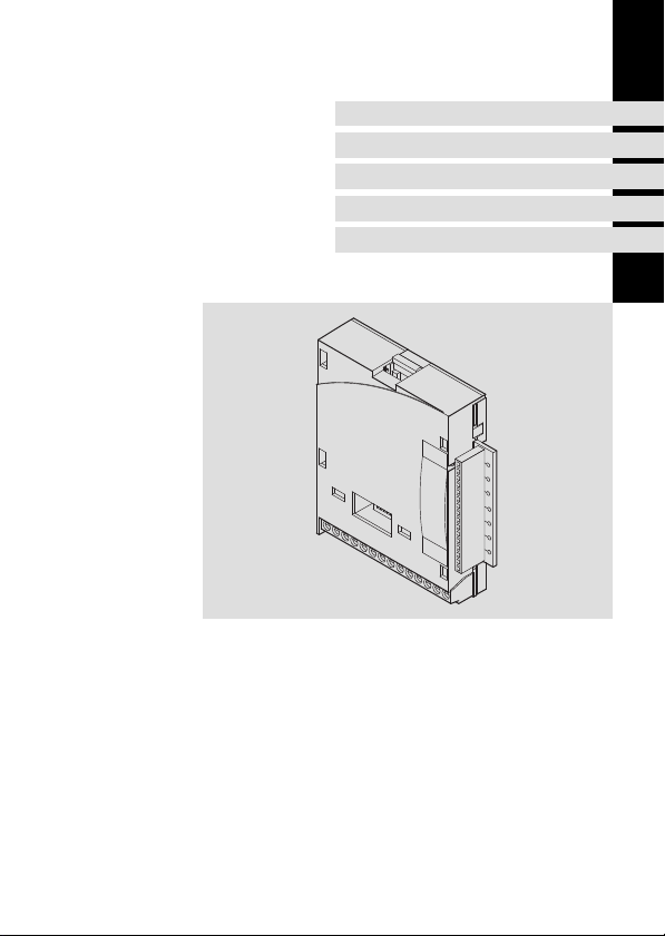
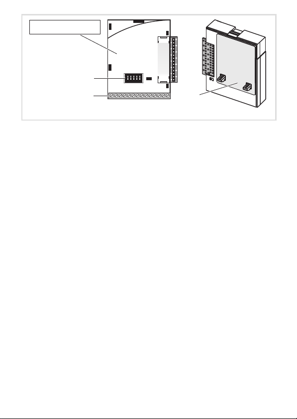
Legende zur Abbildung auf der Ausklappseite siehe
Funktionsmodul E82ZAFBC201
Schalter zur Konfigurierung des analogen Frequenzsollwertes an Klemme X3/8
0
Digitale und analoge Ein− und Ausgänge, Steckerleiste X3
1
Typenschild
2
0Abb. 0Tab. 0
^ 21
^ 19
^ 5
I Tipp!
Aktuelle Dokumentationen und Software−Updates zu Lenze Produkten finden
Sie im Internet jeweils im Bereich "Services & Downloads" unter
http://www.Lenze.com
4
l
EDK82ZAFBC−201 DE/EN/FR 5.0
Page 5
Gültigkeit
APPLICATION
010 / 3A22
Diese Anleitung ist gültig für
ƒ Funktionsmodule Bus−I/O ab Version E82ZAFBC2013B
Diese Anleitung ist nur gültig zusammen mit der zugehörigen Betriebsanleitung der für den
Einsatz zulässigen Grundgeräte.
Identifikation
APPLICATION
010/ 3A22
Gerätereihe
Bus−I/O
Gerätegeneration
Variante
201: verlackte Ausführung
Hardwarestand
EDK82ZAFBC−201 DE/EN/FR 5.0
L
Type
Id.-No.
Prod.-No.
Ser.-No.
E82AF000P0B201XX
l
E82ZAFX005
E82ZAF B C 201 3B
5
Page 6

Bestellbezeichnung
E82ZAFBC2013B
Funktion
Das Funktionsmodul ermöglicht das Ansteuern von Lenze−Frequenzumrichtern
8200 motec mit analogen und digitalen Steuersignalen und die Kopplung an ein serielles
Kommunikationssystem.
Einsetzbarkeit
Das Funktionsmodul E82ZAFBC201 ist einsetzbar mit folgendem Grundgerät und
folgenden Feldbus−Funktionsmodulen:
Typ Bezeichnung ab Version
Frequenzumrichter 8200 motec 3,0 7,5 kW VB21
Feldbus−Funktionsmodul
1)
Die digitalen Eingänge auf dem Feldbus−Funktionsmodul können nicht benutzt werden.
CANopen E82ZAFUC001 3B05
DeviceNet E82ZAFVC001 3B05
INTERBUS E82ZAFIC001 3A10
LECOM−B (RS485) E82ZAFLC001 3A10
PROFIBUS E82ZAFPC001 3A10
PROFIBUS−IO E82ZAFPC201
Systembus−CAN E82ZAFCC001 3A10
1)
VA05
6
l
EDK82ZAFBC−201 DE/EN/FR 5.0
Page 7

Inhalt i
1 Sicherheitshinweise 8 . . . . . . . . . . . . . . . . . . . . . . . . . . . . . . . . . . . . . . . . . . . . . . . .
Definition der verwendeten Hinweise 8 . . . . . . . . . . . . . . . . . . . . . . . . . . . . . . . . .
Restgefahren 9 . . . . . . . . . . . . . . . . . . . . . . . . . . . . . . . . . . . . . . . . . . . . . . . . . . . . . .
2 Technische Daten 10 . . . . . . . . . . . . . . . . . . . . . . . . . . . . . . . . . . . . . . . . . . . . . . . . . .
Allgemeine Daten und Einsatzbedingungen 10 . . . . . . . . . . . . . . . . . . . . . . . . . . . .
Anschlussdaten 11 . . . . . . . . . . . . . . . . . . . . . . . . . . . . . . . . . . . . . . . . . . . . . . . . . . . .
Abmessungen 12 . . . . . . . . . . . . . . . . . . . . . . . . . . . . . . . . . . . . . . . . . . . . . . . . . . . . .
3 Lieferumfang 13 . . . . . . . . . . . . . . . . . . . . . . . . . . . . . . . . . . . . . . . . . . . . . . . . . . . . . .
4 Mechanische Installation 14 . . . . . . . . . . . . . . . . . . . . . . . . . . . . . . . . . . . . . . . . . . . .
5 Elektrische Installation 15 . . . . . . . . . . . . . . . . . . . . . . . . . . . . . . . . . . . . . . . . . . . . . .
EMV−gerechte Verdrahtung 15 . . . . . . . . . . . . . . . . . . . . . . . . . . . . . . . . . . . . . . . . . .
Verdrahtung 16 . . . . . . . . . . . . . . . . . . . . . . . . . . . . . . . . . . . . . . . . . . . . . . . . . . . . . .
6 Gerät zusammenbauen 20 . . . . . . . . . . . . . . . . . . . . . . . . . . . . . . . . . . . . . . . . . . . . .
7 Inbetriebnahme 21 . . . . . . . . . . . . . . . . . . . . . . . . . . . . . . . . . . . . . . . . . . . . . . . . . . .
Vor dem ersten Einschalten 21 . . . . . . . . . . . . . . . . . . . . . . . . . . . . . . . . . . . . . . . . . .
Schalterstellung 21 . . . . . . . . . . . . . . . . . . . . . . . . . . . . . . . . . . . . . . . . . . . . . . . . . . .
Mit Lenze−Einstellung 22 . . . . . . . . . . . . . . . . . . . . . . . . . . . . . . . . . . . . . . . . . . . . . . .
EDK82ZAFBC−201 DE/EN/FR 5.0
l
7
Page 8

1 Sicherheitshinweise
Definition der verwendeten Hinweise
1 Sicherheitshinweise
Definition der verwendeten Hinweise
Um auf Gefahren und wichtige Informationen hinzuweisen, werden in dieser Dokumentation folgende Piktogramme und Signalwörter verwendet:
Sicherheitshinweise
Aufbau der Sicherheitshinweise:
} Gefahr!
(kennzeichnet die Art und die Schwere der Gefahr)
Hinweistext
(beschreibt die Gefahr und gibt Hinweise, wie sie vermieden werden kann)
Piktogramm und Signalwort Bedeutung
Gefahr von Personenschäden durch gefährliche elektrische Spannung
{ Gefahr!
} Gefahr!
( Stop!
Hinweis auf eine unmittelbar drohende Gefahr, die den
Tod oder schwere Verletzungen zur Folge haben kann,
wenn nicht die entsprechenden Maßnahmen getroffen
werden.
Gefahr von Personenschäden durch eine allgemeine Gefahrenquelle
Hinweis auf eine unmittelbar drohende Gefahr, die den
Tod oder schwere Verletzungen zur Folge haben kann,
wenn nicht die entsprechenden Maßnahmen getroffen
werden.
Gefahr von Sachschäden
Hinweis auf eine mögliche Gefahr, die Sachschäden zur
Folge haben kann, wenn nicht die entsprechenden Maßnahmen getroffen werden.
8
l
EDK82ZAFBC−201 DE/EN/FR 5.0
Page 9

Anwendungshinweise
Piktogramm und Signalwort Bedeutung
Sicherheitshinweise
Restgefahren
1
) Hinweis!
I Tipp!
,
Restgefahren
Wichtiger Hinweis für die störungsfreie Funktion
Nützlicher Tipp für die einfache Handhabung
Verweis auf andere Dokumentation
} Gefahr!
Beachten Sie die in den Anleitungen zum Grundgerät enthaltenen
Sicherheitshinweise und Restgefahren.
EDK82ZAFBC−201 DE/EN/FR 5.0
l
9
Page 10

2 Technische Daten
Allgemeine Daten und Einsatzbedingungen
2 Technische Daten
Allgemeine Daten und Einsatzbedingungen
Allgemeine Daten
Konformität und Approbation
Approbation
UL UL 508C Industrial Control Equipment
Personenschutz und Geräteschutz
Schutzart
Einsatzbedingungen
Umgebungsbedingungen
Klimatisch
Lagerung IEC/EN 60721−3−1 1K3 (−25 ... +60 °C)
Transport IEC/EN 60721−3−2 2K3 (−25 ... +70 °C)
Betrieb IEC/EN 60721−3−3 3K3 (−20 ... +60 °C)
Verschmutzung EN 61800−5−1 Verschmutzungsgrad 2
EN 60529 IP20
File No. E132659
10
l
EDK82ZAFBC−201 DE/EN/FR 5.0
Page 11

Technische Daten
Anschlussdaten
Anschlussdaten
X3/
62 Auflösung: 10 Bit
Linearitätsfehler: ±0,5 %
Temperaturfehler: 0,3 % (0 +60°C)
Belastbarkeit I
8
Auflösung: 10 Bit
Linearitätsfehler: ±0,5 %
Temperaturfehler: 0,3 % (0 +60 °C)
Eingangswiderstand
l R
Eingang
l R
9 Belastbarkeit I
7 potentialgetrennt zu Klemme X3/39 (GND2)
20
28
E1
E2
E3
E4
39 potentialgetrennt zu Klemme X3/7 (GND1)
A1 Belastbarkeit:
1)
Eingang
Belastbarkeit: S I
Eingangswiderstand: 3,3 kW
1)
1)
1 = HIGH (+12 +30 V), SPS−Pegel, HTL
0 = LOW (0 +3 V), SPS−Pegel, HTL
= 10 mA, bei interner Versorgung
I
max
= 50 mA, bei externer Versorgung
I
max
wahlweise Frequenzeingang 0 10 kHz einspurig oder 0 ... 1 kHz zweispurig, Konfiguration über
C0425
= 2 mA
max
> 50 kW (bei Spannungssignal)
= 250 W (bei Stromsignal)
= 10 mA
max
= 40 mA
max
2
EDK82ZAFBC−201 DE/EN/FR 5.0
l
11
Page 12
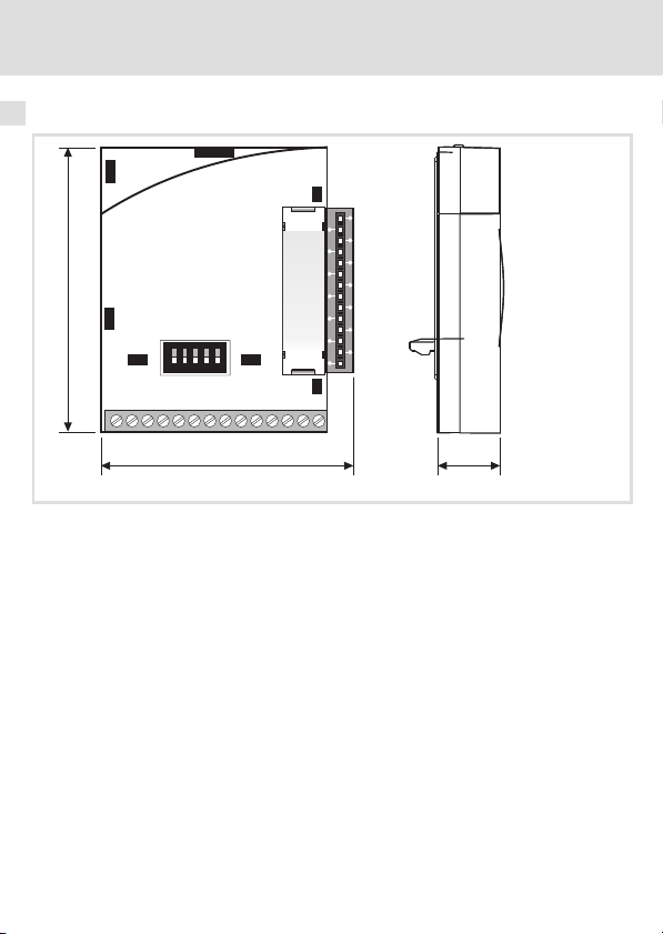
2 Technische Daten
Abmessungen
Abmessungen
64
1122334
4
77
62
8 9 20 28
alle Maße in mm
5
5
E1 E2 E3 E439A1
59
57 15
E82ZAFB009
12
l
EDK82ZAFBC−201 DE/EN/FR 5.0
Page 13
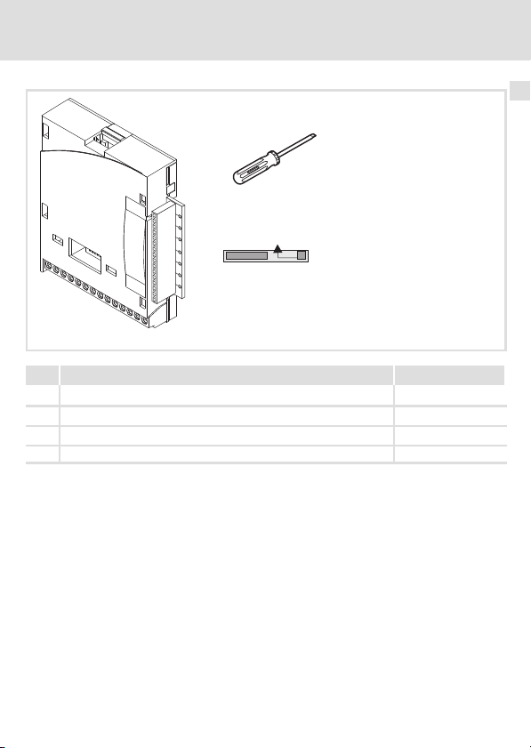
Lieferumfang 3
3 Lieferumfang
1
0
2
Standard-I/O
Pos Lieferumfang siehe
Bus−I/O Funktionsmodul E82ZAFBC201
0
Schraubendreher
1
Aufkleber
2
Montageanleitung
S
E82ZAFB210
EDK82ZAFBC−201 DE/EN/FR 5.0
l
13
Page 14
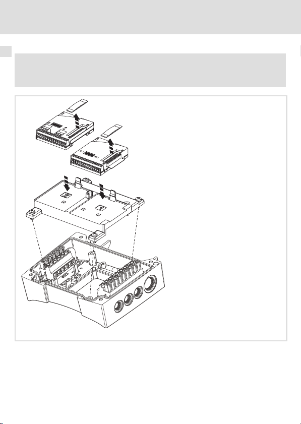
4 Mechanische Installation
4 Mechanische Installation
( Stop!
Das Bus−I/O−Funktionsmodul muss auf Steckplatz 1 gesteckt werden!
1
0
E82ZAFB202
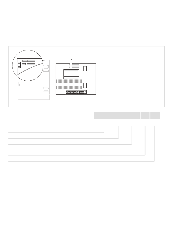
1. Schutzkappen der Funktionsmodule entfernen.
2. Bus−I/O−Funktionsmodul 0 in motec−Trägergehäuse auf Steckplatz 1 einsetzen, bis es
einrastet.
3. Feldbus−Funktionsmodul 1 in motec−Trägergehäuse auf Steckplatz 2 einsetzen, bis es
einrastet.
14
l
EDK82ZAFBC−201 DE/EN/FR 5.0
Page 15
Elektrische Installation
EMV−gerechte Verdrahtung
5 Elektrische Installation
EMV−gerechte Verdrahtung
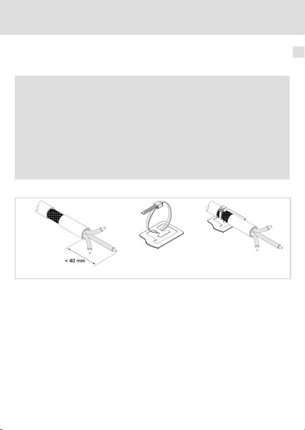
Für eine EMV−gerechte Verdrahtung beachten Sie folgende Punkte:
) Hinweis!
ƒ Steuerleitungen getrennt von Motorleitungen verlegen.
ƒ Schirme so weit wie möglich an die Klemmen führen (ungeschirmte
Aderlänge < 40 mm).
ƒ Legen Sie die Schirme der Steuerleitungen bzw. Datenleitungen wie folgt
auf:
– Einseitig am Umrichter bei Leitungen mit analogen Signalen.
– Beidseitig bei Leitungen mit digitalen Signalen.
ƒ Beachten Sie die weiteren Hinweise zur EMV−gerechten Verdrahtung in der
Dokumentation des Grundgerätes.
Schirm auflegen
8200mot045/046/047
1. Leitung vorbereiten.
2. Kabelbinder ins Schirmblech einlegen.
3. Leitung einlegen und Kabelbinder anziehen. Die Abschirmung muss fest mit dem
Schirmblech verbunden sein.
5
EDK82ZAFBC−201 DE/EN/FR 5.0
l
15
Page 16
5 Elektrische Installation
Verdrahtung
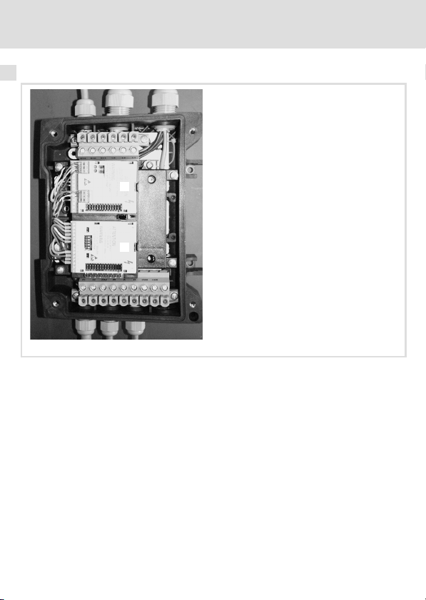
Verdrahtung
0
1
1. Feldbus−Funktionsmodul 0 verdrahten.
– Ummantelung des Buskabels ca. 10 cm entfernen.
– Schirm mit Kabelbinder auf Schirmblech auflegen.
– Feldbus−Funktionsmodul verdrahten (siehe dazugehörige Montageanleitung).
Klemme 28 (Reglersperre) des Bus−Funktionsmoduls 0 ist inaktiv. Reglersperre wird ge-
schaltet über Klemme 28 des Bus−I/O−Funktionsmoduls.
2. Bus−I/O−Funktionsmodul 1 verdrahten (Klemmenbelegung ^ 19).
3. Netz und Motor anschließen (siehe Montageanleitung 8200 motec).
E82ZAFB211
16
l
EDK82ZAFBC−201 DE/EN/FR 5.0
Page 17
Daten der Anschlussklemmen
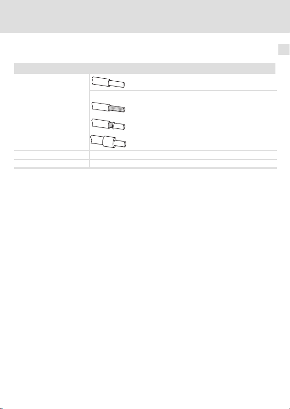
Klemmenleiste mit Schraubanschluss
Anschlussmöglichkeiten
Anzugsmoment 0,22 ... 0,25 Nm (1.9 ... 2.2 lb−in)
Abisolierlänge 5 mm
starr: 1,5 mm
flexibel:
ohne Aderendhülse
2
1,0 mm
(AWG 18)
mit Aderendhülse, ohne Kunststoffhülse
2
(AWG 20)
0,5 mm
mit Aderendhülse, mit Kunststoffhülse
2
0,5 mm
(AWG 20)
Elektrische Installation
Verdrahtung
2
(AWG 16)
5
EDK82ZAFBC−201 DE/EN/FR 5.0
l
17
Page 18
5 Elektrische Installation
Verdrahtung
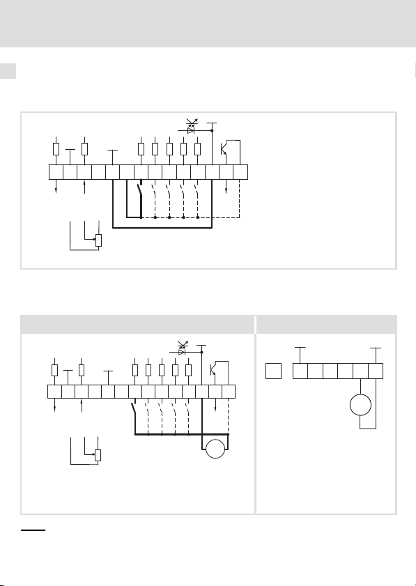
Versorgung über die interne Spannungsquelle (X3/20):
ƒ X3/28, Reglersperre (CINH)
ƒ X3/E1 .... X3/E4, digitale Eingänge
GND2
GND1
62 8
X3
AOUT1
Versorgung über eine externe Spannungsquelle:
GND1
+5V
9
897
0 … +5 V
+20V
20 28
1k … 10k
77
AIN1
E1 E2E3E439A1
DIGOUT1
59
ƒ X3/28, Reglersperre (CINH)
ƒ X3/E1 ... X3/E4, digitale Eingänge
Bus−I/O−Funktionsmodul Feldbus−Funktionsmodul
GND1
GND1
+20V
+5V
6278 9 20 28E1E2 E3 E4 39 A1 59
X3
AOUT1
AIN1
897
0 … +5 V
7
1k … 10k
Für den Betrieb notwendige Mindestverdrahtung
GND2
DIGOUT1
_
+
24 V ext.
(+12 V DC - 0 %
...
+30 V DC + 0 %,
max. 120 mA)
E82ZxFB005 E82ZxFB005a
...
GND1
7
39 28 59 720
24 V ext.
E82ZxFB004
GND1
+
_
18
l
EDK82ZAFBC−201 DE/EN/FR 5.0
Page 19

Elektrische Installation
Verdrahtung
5
X3/ Signaltyp Funktion Pegel
62 Analoger
Ausgang
7 − GND1, Bezugspotential für analoge Signale −
8 Analoger
Eingang
9 − Interne, stabilisierte DC−Spannungsquelle für Soll-
20 − Interne DC−Spannungsquelle zum Ansteuern der
28
3)
E1
3)
E2
Digitale
Eingänge
E3 Gleichstrombremse (DCB) 1 = DCB
E4 Drehrichtungsumkehr
39 − GND2, Bezugspotential für digitale Signale −
A1
Digitaler
Ausgang
59 − DC−Versorgung für X3/A1
1)
Ausgangspegel 0 +10 V: Offset (C0109/C0422) und Verstärkung (C0108/C0420) anpassen
2)
Offset (C0026) und Verstärkung (C0027) für jedes Funktionsmodul separat abgleichen:
Nach Austausch des Funktionsmoduls oder des Grundgerätes
Nach Laden der Lenze−Einstellung
3)
Wahlweise Frequenzeingang 0 10 kHz einspurig oder 0 ... 1 kHz zweispurig, Konfiguration über
C0425
Ausgangsfrequenz 0 +6 V
Eingang für Istwert oder Sollwert
Bereich umschalten mit DIP−Schalter und in C0034
l Spannungssignal
l Stromsignal
wertpotentiometer
digitalen Eingänge und Ausgänge
Reglersperre (CINH) 1 = Freigabe
Aktivierung von Festfrequenzen (JOG)
JOG1 = 20 Hz
JOG2 = 30 Hz
JOG3 = 40 Hz
Rechts−/Linkslauf (CW/CCW)
Betriebsbereit bei
– interner Versorgung:
– externer Versorgung:
– intern (Brücke zu X3/20):
– extern:
(Lenze−Einstellung: Fettdruck)
1)
0 +10 V
0 +5 V
0 +10 V
−10 V +10 V
0 +20 mA
+4 +20 mA
+4 +20 mA (drahtbruchüberwacht)
+5,2 V
+20 V ±10 % (Bezug: X3/7)
JOG1 1 0
JOG2 0 1
JOG3 1 1
CW 0
CCW 1
0 +20 V
0 +24 V
+20 V
+24 V
2)
E1 E2
E4
EDK82ZAFBC−201 DE/EN/FR 5.0
l
19
Page 20
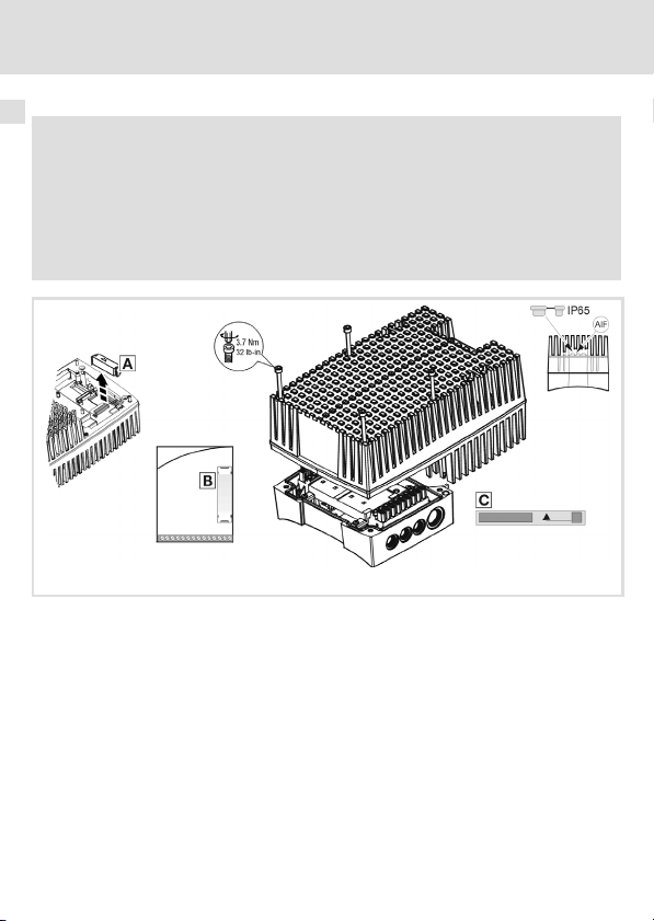
6 Gerät zusammenbauen
6 Gerät zusammenbauen
( Stop!
ƒ Um den motec und die Funktionsmodule nicht zu beschädigen, unbedingt
vor dem Zusammenbau
– die Schutzkappe jedes Funktionsmoduls 1 entfernen und aufbewahren.
– die FIF−Abdeckkappe 0 entfernen und aufbewahren.
ƒ Vor Inbetriebnahme mit dem Aufkleber 2, der dem Funktionsmodul
beiliegt, das motec−Typenschild vervollständigen.
8200mot059
20
l
EDK82ZAFBC−201 DE/EN/FR 5.0
Page 21

Inbetriebnahme
Vor dem ersten Einschalten
7 Inbetriebnahme
Vor dem ersten Einschalten
Die Inbetriebnahme ist abhängig von der Kombination der verwendeten Geräte (Bus−I/O−
und Feldbus−Funktionsmodul). Die Vorgehensweise bei der Inbetriebnahme ist in den Dokumentationen zum Feldbus−System und zum Frequenzumrichter beschrieben.
Schalterstellung
ON
1ON234
5
OFF
7
) Hinweis!
DIP−Schalter und C0034 unbedingt auf den gleichen Bereich einstellen, da
sonst das analoge Eingangssignal an X3/8 durch das Grundgerät falsch
interpretiert wird.
Wird ein Sollwertpotentiometer intern über X3/9 versorgt, unbedingt
DIP−Schalter auf Spannungsbereich 0 ... 5 V einstellen. Andernfalls kann nicht
der ganze Drehzahlbereich durchfahren werden.
Signal an X3/8
1 2 3 4 5
0 ... 5 V OFF OFF ON OFF OFF 0
0 ... 10 V (Lenze−Einstellung) OFF OFF ON OFF ON 0
0 ... 20 mA OFF OFF ON ON OFF 0
4 ... 20 mA OFF OFF ON ON OFF 1
4 ... 20 mA drahtbruchüberwacht OFF OFF ON ON OFF 3
−10 V ... +10 V ON ON OFF OFF OFF 2
EDK82ZAFBC−201 DE/EN/FR 5.0
l
Schalterstellung
C0034
21
Page 22

7 Inbetriebnahme
Mit Lenze−Einstellung
Mit Lenze−Einstellung
) Hinweis!
ƒ Das Grundgerät ist nur funktionsfähig, wenn HIGH−Pegel an X3/28 anliegt
(Reglerfreigabe über Klemme).
– Beachten Sie, dass die Reglersperre über mehrere Quellen gesetzt
werden kann. Die Quellen wirken wie eine Reihenschaltung von
Schaltern.
– Wenn der Antrieb trotz Reglerfreigabe über X3/28 nicht anläuft,
überprüfen Sie, ob noch über eine andere Quelle Reglersperre gesetzt
ist. Eine andere Quelle könnte die s−Taste des Keypad sein.
22
l
EDK82ZAFBC−201 DE/EN/FR 5.0
Page 23

Inbetriebnahme
Mit Lenze−Einstellung
7
EDK82ZAFBC−201 DE/EN/FR 5.0
l
23
Page 24

Legend for fold−out page See
E82ZAFBC201 function module
Switch for the configuration of the analog frequency setpoint at terminal X3/8
0
Digital and analog inputs and outputs, plug connector X3
1
Nameplate
2
0Fig. 0Tab. 0
I Tip!
Current documentation and software updates concerning Lenze products can
be found on the Internet in the "Services & Downloads" area under
http://www.Lenze.com
^ 41
^ 39
^ 25
24
l
EDK82ZAFBC−201 DE/EN/FR 5.0
Page 25

Validity
APPLICATION
010 / 3A22
These instructions are valid for
ƒ Bus−I/O function modules as of version E82ZAFBC2013B
These instructions are only valid together with the Operating Instructions for the standard
devices permitted for the application.
Identification
APPLICATION
010/ 3A22
Series
Bus−I/O
Generation
Variant
201: coated design
Hardware version
EDK82ZAFBC−201 DE/EN/FR 5.0
L
Type
Id.-No.
Prod.-No.
Ser.-No.
E82AF000P0B201XX
l
E82ZAFX005
E82ZAF B C 201 3B
25
Page 26

Order designation
E82ZAFBC2013B
Function
The function module enables the 8200 motec frequency inverters from Lenze to be
controlled through analog and digital control signals and to be connected to a serial
communication system.
Application range
The E82ZAFBC201 function module can be used together with the following basic device
and the following fieldbus function modules:
Type Designation as of version
Frequency inverter 8200 motec 3.0 7.5 kW VB21
Fieldbus function
module
1)
The digital inputs of the fieldbus function module cannot be used.
CANopen E82ZAFUC001 3B05
DeviceNet E82ZAFVC001 3B05
INTERBUS E82ZAFIC001 3A10
LECOM−B (RS485) E82ZAFLC001 3A10
PROFIBUS E82ZAFPC001 3A10
PROFIBUS−IO E82ZAFPC201
System bus CAN E82ZAFCC001 3A10
1)
VA05
26
l
EDK82ZAFBC−201 DE/EN/FR 5.0
Page 27

Contents i
1 Safety instructions 28 . . . . . . . . . . . . . . . . . . . . . . . . . . . . . . . . . . . . . . . . . . . . . . . . .
Definition of notes used 28 . . . . . . . . . . . . . . . . . . . . . . . . . . . . . . . . . . . . . . . . . . . . .
Residual hazards 29 . . . . . . . . . . . . . . . . . . . . . . . . . . . . . . . . . . . . . . . . . . . . . . . . . . .
2 Technical data 30 . . . . . . . . . . . . . . . . . . . . . . . . . . . . . . . . . . . . . . . . . . . . . . . . . . . . .
General data and operating conditions 30 . . . . . . . . . . . . . . . . . . . . . . . . . . . . . . . . .
Connection data 31 . . . . . . . . . . . . . . . . . . . . . . . . . . . . . . . . . . . . . . . . . . . . . . . . . . .
Dimensions 32 . . . . . . . . . . . . . . . . . . . . . . . . . . . . . . . . . . . . . . . . . . . . . . . . . . . . . . .
3 Scope of supply 33 . . . . . . . . . . . . . . . . . . . . . . . . . . . . . . . . . . . . . . . . . . . . . . . . . . . .
4 Mechanical installation 34 . . . . . . . . . . . . . . . . . . . . . . . . . . . . . . . . . . . . . . . . . . . . .
5 Electrical installation 35 . . . . . . . . . . . . . . . . . . . . . . . . . . . . . . . . . . . . . . . . . . . . . . .
Wiring according to EMC 35 . . . . . . . . . . . . . . . . . . . . . . . . . . . . . . . . . . . . . . . . . . . .
Wiring 36 . . . . . . . . . . . . . . . . . . . . . . . . . . . . . . . . . . . . . . . . . . . . . . . . . . . . . . . . . . .
6 Device assembly 40 . . . . . . . . . . . . . . . . . . . . . . . . . . . . . . . . . . . . . . . . . . . . . . . . . . .
7 Commissioning 41 . . . . . . . . . . . . . . . . . . . . . . . . . . . . . . . . . . . . . . . . . . . . . . . . . . . .
Before switching on 41 . . . . . . . . . . . . . . . . . . . . . . . . . . . . . . . . . . . . . . . . . . . . . . . .
Switch position 41 . . . . . . . . . . . . . . . . . . . . . . . . . . . . . . . . . . . . . . . . . . . . . . . . . . . .
Commissioning using Lenze settings 42 . . . . . . . . . . . . . . . . . . . . . . . . . . . . . . . . . . .
EDK82ZAFBC−201 DE/EN/FR 5.0
l
27
Page 28

1 Safety instructions
Definition of notes used
1 Safety instructions
Definition of notes used
The following pictographs and signal words are used in this documentation to indicate
dangers and important information:
Safety instructions
Structure of safety instructions:
} Danger!
(characterises the type and severity of danger)
Note
(describes the danger and gives information about how to prevent dangerous
situations)
Pictograph and signal word Meaning
Danger of personal injury through dangerous electrical
{ Danger!
} Danger!
( Stop!
voltage.
Reference to an imminent danger that may result in
death or serious personal injury if the corresponding
measures are not taken.
Danger of personal injury through a general source of
danger.
Reference to an imminent danger that may result in
death or serious personal injury if the corresponding
measures are not taken.
Danger of property damage.
Reference to a possible danger that may result in
property damage if the corresponding measures are not
taken.
28
l
EDK82ZAFBC−201 DE/EN/FR 5.0
Page 29

Application notes
Pictograph and signal word Meaning
Safety instructions
Residual hazards
1
) Note!
I Tip!
,
Residual hazards
Important note to ensure troublefree operation
Useful tip for simple handling
Reference to another documentation
} Danger!
Observe the safety instructions and residual hazards included in the
instructions for the standard device.
EDK82ZAFBC−201 DE/EN/FR 5.0
l
29
Page 30

2 Technical data
General data and operating conditions
2 Technical data
General data and operating conditions
General data
Conformity and approval
Approval
UL UL 508C Industrial Control Equipment
Protection of persons and equipment
Type of protection
Operating conditions
Ambient conditions
Climatic conditions
Storage IEC/EN 60721−3−1 1K3 (−25 ... +60 °C)
Transport IEC/EN 60721−3−2 2K3 (−25 ... +70 °C)
Operation IEC/EN 60721−3−3 3K3 (−20 ... +60 °C)
Pollution EN 61800−5−1 Degree of pollution 2
EN 60529 IP20
File No. E132659
30
l
EDK82ZAFBC−201 DE/EN/FR 5.0
Page 31

Technical data
Connection data
Connection data
X3/
62 Resolution: 10 bit
Linearity error: ±0.5 %
Temperature error: 0.3 % (0 +60°C)
Carrying capacity I
8
Resolution: 10 bit
Linearity error: ±0.5 %
Temperature error: 0.3 % (0 +60 °C)
Input resistance
l R
> 50 kW (voltage signal)
input
l R
= 250 W (current signal)
9 Carrying capacity I
7 Electrically isolated to terminal X3/39 (GND2)
20
28
E1
E2
E3
E4
39 Electrically isolated to terminal X3/7 (GND1)
A1 Carrying capacity:
1)
input
Carrying capacity: S I
Input resistance: 3.3 kW
1)
1)
1 = HIGH (+12 +30 V), PLC level, HTL
0 = LOW (0 +3 V), PLC level, HTL
= 10 mA, for internal supply
I
max
= 50 mA, for external supply
I
max
Alternatively frequency input 0 10 kHz single−tracked or 0 ... 1 kHz double−tracked, configuration
via C0425
max
max
= 2 mA
= 10 mA
= 40 mA
max
2
EDK82ZAFBC−201 DE/EN/FR 5.0
l
31
Page 32

2 Technical data
Dimensions
Dimensions
64
1122334
77
62
8 9 20 28
All dimensions in mm
5
5
4
E1 E2 E3 E439A1
59
57 15
E82ZAFB009
32
l
EDK82ZAFBC−201 DE/EN/FR 5.0
Page 33

Scope of supply 3
3 Scope of supply
1
0
2
Standard-I/O
Pos. Scope of supply see
E82ZAFBC201 bus−I/O function module
0
Screw driver
1
Sticker
2
Mounting Instructions
S
E82ZAFB210
EDK82ZAFBC−201 DE/EN/FR 5.0
l
33
Page 34

4 Mechanical installation
4 Mechanical installation
( Stop!
The bus−I/O function module has to be plugged into receptacle 1!
1
0
E82ZAFB202
1. Remove protecting caps of function modules.
2. Insert bus−I/O function module 0 into receptacle 1 of motec carrier housing until it
snaps into place.
3. Insert fieldbus function module 1 into receptacle 2 of motec carrier housing until it
snaps into place.
34
l
EDK82ZAFBC−201 DE/EN/FR 5.0
Page 35

Electrical installation
Wiring according to EMC
5 Electrical installation
Wiring according to EMC
Please observe the following for wiring according to EMC guidelines:
) Note!
ƒ Separate control cables from motor cables.
ƒ Lead the shields as far as possible to the terminals (unshielded core length
< 40 mm).
ƒ Connect control and data cable shields as follows:
– Analog signal cable shields must be connected with one end at the
inverter.
– Digital signal cable shields must be connected with both ends.
ƒ More information about wiring according to EMC guidelines can be
obtained from the corresponding documentation for the standard device.
How to connect the shield
8200mot045/046/047
1. Prepare cable.
2. Insert cable tie into shield sheet.
3. Insert cable and tighten cable tie. Shield and shield sheet must be tightly connected.
5
EDK82ZAFBC−201 DE/EN/FR 5.0
l
35
Page 36

5 Electrical installation
Wiring
Wiring
0
1
1. Wire the fieldbus function module 0.
– Remove approx. 10 cm of the cable sheath.
– Connect the shield to the shield sheet using the cable tie.
– Wire the fieldbus function module (see corresponding Mounting Instructions).
Terminal 28 (controller inhibit) of the bus function module 0 is inactive. Controller is
inhibited via terminal 28 of the bus−I/O function module.
2. Wire the bus−I/O function module 1 (terminal assignment
3. Connect mains and motor (see Mounting Instructions for the 8200 motec).
^ 39).
E82ZAFB211
36
l
EDK82ZAFBC−201 DE/EN/FR 5.0
Page 37

Terminal data
Terminal strip with screw connection
Possible connections
Tightening torque 0.22 ... 0.25 Nm (1.9 ... 2.2 lb−in)
Bare end 5 mm
rigid: 1.5 mm
flexible:
without wire end ferrule
2
1.0 mm
(AWG 18)
with wire end ferrule, without plastic sleeve
2
(AWG 20)
0.5 mm
with wire end ferrule, with plastic sleeve
2
0.5 mm
(AWG 20)
Electrical installation
2
(AWG 16)
Wiring
5
EDK82ZAFBC−201 DE/EN/FR 5.0
l
37
Page 38

5 Electrical installation
Wiring
Supply via the internal voltage source (X3/20):
ƒ X3/28, controller inhibit (CINH)
ƒ X3/E1 .... X3/E4, digital inputs
GND2
GND1
62 8
X3
AOUT1
Supply via an external voltage source:
GND1
+5V
9
897
0 … +5 V
+20V
20 28
1k … 10k
77
AIN1
E1 E2E3E439A1
DIGOUT1
59
ƒ X3/28, controller inhibit (CINH)
ƒ X3/E1 ... X3/E4, digital inputs
Bus−I/O function module Fieldbus function module
GND1
GND1
+20V
+5V
6278 9 20 28E1E2 E3 E4 39 A1 59
X3
AOUT1
AIN1
897
0 … +5 V
7
1k … 10k
The min. wiring requirements for operation
GND2
DIGOUT1
_
+
24 V ext.
(+12 V DC - 0 %
...
+30 V DC + 0 %,
max. 120 mA)
E82ZxFB005 E82ZxFB005a
...
GND1
7
39 28 59 720
24 V ext.
E82ZxFB004
GND1
+
_
38
l
EDK82ZAFBC−201 DE/EN/FR 5.0
Page 39

Electrical installation
Wiring
5
X3/ Signal type Function Level
62 Analog
output
7 − GND1, reference potential for analog signals −
8 Analog
input
9 − Internal, stabilised DC voltage supply for setpoint
20 − Internal DC voltage supply for control of digital
28
3)
E1
3)
E2
Digital
inputs
E3 DC−injection brake (DCB) 1 = DCB
E4 Change of direction of rotation
39 − GND2, reference potential for digital signals −
A1
Digital
output
59 − DC supply for X3/A1
1)
Output level 0 +10 V: Adapt offset (C0109/C0422) and gain (C0108/C0420)
2)
Adjust offset (C0026) and gain (C0027) separately for each function module:
After replacing the function module or the standard device
After loading the Lenze setting
3)
Alternatively frequency input 0 10 kHz single−tracked or 0 ... 1 kHz double−tracked, configuration
via C0425
Output frequency 0 +6 V
Input for actual value or setpoint
Change range using the DIP switch and C0034
l Voltage signal
l Current signal
potentiometer
inputs and outputs
Controller inhibit (CINH) 1 = enable
Activation of JOG frequencies
JOG1 = 20 Hz
JOG2 = 30 Hz
JOG3 = 40 Hz
CW/CCW rotation
Ready for operation with
– internal supply:
– external supply:
– internal (jumper to X3/20):
– external:
(Lenze setting: Bold print)
1)
0 +10 V
0 +5 V
0 +10 V
−10 V +10 V
0 +20 mA
+4 +20 mA
+4 +20 mA (open−circuit
monitored)
+5.2 V
+20 V ±10 % (ref.: X3/7)
JOG1 1 0
JOG2 0 1
JOG3 1 1
CW 0
CCW 1
0 +20 V
0 +24 V
+20 V
+24 V
2)
E1 E2
E4
EDK82ZAFBC−201 DE/EN/FR 5.0
l
39
Page 40

6 Device assembly
6 Device assembly
( Stop!
ƒ In order to avoid damages of the motec and the function modules, proceed
as follows before starting to assemble:
– Remove and keep the protecting cap of each function module 1.
– Remove and keep the FIF cap 0.
ƒ Complete the motec nameplate with the sticker 2 that is delivered
together with the function module.
8200mot059
40
l
EDK82ZAFBC−201 DE/EN/FR 5.0
Page 41

Commissioning
Before switching on
7 Commissioning
Before switching on
Commissioning depends on the device combination (bus−I/O and fieldbus function
module). The commissioning procedure is described in the documentation on the fieldbus
system and the frequency inverter.
Switch position
ON
1ON234
5
OFF
7
) Note!
DIP switch and C0034 must be set for the same value range, otherwise the
analog input signal at X3/8 will be interpreted incorrectly by the standard
device.
If a setpoint potentiometer is internally supplied through X3/9, the DIP switch
must be set to a voltage range of 0 ... 5 V. Otherwise it is not possible to use the
whole speed range.
Signal at X3/8
1 2 3 4 5
0 ... 5 V OFF OFF ON OFF OFF 0
0 ... 10 V (Lenze setting) OFF OFF ON OFF ON 0
0 ... 20 mA OFF OFF ON ON OFF 0
4 ... 20 mA OFF OFF ON ON OFF 1
4 ... 20 mA Open−circuit
−10 V ... +10 V ON ON OFF OFF OFF 2
EDK82ZAFBC−201 DE/EN/FR 5.0
monitoring
OFF OFF ON ON OFF 3
l
Switch position
C0034
41
Page 42

7 Commissioning
Commissioning using Lenze settings
Commissioning using Lenze settings
) Note!
ƒ The controller is only ready for operation if a HIGH signal is applied to
X3/28 (controller enable via terminal).
– Please observe that the controller can be inhibited through various
sources. All sources act like a series connection of switches.
– If the drive does not start although the controller has been enabled via
X3/28, check whether the controller has been inhibited through a
different source. Another source could be the s key of the keypad.
42
l
EDK82ZAFBC−201 DE/EN/FR 5.0
Page 43

Commissioning using Lenze settings
Commissioning
7
EDK82ZAFBC−201 DE/EN/FR 5.0
l
43
Page 44

Légende de l’illustration de la page dépliante Voir
Module de fonction E82ZAFBC201
Interrupteur pour la configuration de la consigne de fréquence analogique au
0
niveau de la borne X3/8
Entrées et sorties numériques et analogiques, bornier enfichable X3
1
Plaque signalétique
2
0Fig. 0Tab. 0
I Conseil !
Les mises à jour de logiciels et les documentations récentes relatives aux
produits Lenze sont disponibles dans la zone "Téléchargements" du site
Internet :
http://www.Lenze.com
^ 61
^ 59
^ 45
44
l
EDK82ZAFBC−201 DE/EN/FR 5.0
Page 45

Validité
APPLICATION
010 / 3A22
Le présent document s’applique au produit suivant :
ƒ Modules de fonction bus E/S à partir de la version E82ZAFBC2013B
Ce document est uniquement valable avec la documentation relative aux appareils de base
compatibles.
Identification
APPLICATION
010/ 3A22
Série d’appareils
Bus E/S
Génération d’appareils
Variante
201 : version vernie
Version matérielle
EDK82ZAFBC−201 DE/EN/FR 5.0
L
Type
Id.-No.
Prod.-No.
Ser.-No.
E82AF000P0B201XX
l
E82ZAFX005
E82ZAF b c 201 3B
45
Page 46

Référence de commande
E82ZAFBC2013B
Fonction
Le module de fonction permet de relier les convertisseurs de fréquence 8200 motec de Lenze
à un système de communication série et de les commander via signaux analogiques et
numériques.
Utilisation
Le module de fonction E82ZAFBC201 peut être utilisé sur les appareils de base et
conjointement avec les modules de fonction bus de terrain suivants :
Type Désignation A partir de la version
Convertisseurs de
fréquence
Module de fonction bus
de terrain
1)
Les entrées numériques présentes sur le module de fonction bus de terrain ne peuvent pas être
utilisées.
8200 motec 3,0 7,5 kW VB21
CANopen E82ZAFUC001 3B05
DeviceNet E82ZAFVC001 3B05
INTERBUS E82ZAFIC001 3A10
LECOM−B (RS485) E82ZAFLC001 3A10
PROFIBUS E82ZAFPC001 3A10
PROFIBUS−IO E82ZAFPC201
Bus Système CAN E82ZAFCC001 3A10
1)
VA05
46
l
EDK82ZAFBC−201 DE/EN/FR 5.0
Page 47

Sommaire i
1 Consignes de sécurité 48 . . . . . . . . . . . . . . . . . . . . . . . . . . . . . . . . . . . . . . . . . . . . . . .
Définition des conventions utilisées 48 . . . . . . . . . . . . . . . . . . . . . . . . . . . . . . . . . . .
Dangers résiduels 49 . . . . . . . . . . . . . . . . . . . . . . . . . . . . . . . . . . . . . . . . . . . . . . . . . .
2 Spécifications techniques 50 . . . . . . . . . . . . . . . . . . . . . . . . . . . . . . . . . . . . . . . . . . .
Caractéristiques générales et conditions d’utilisation 50 . . . . . . . . . . . . . . . . . . . . .
Données de raccordement 51 . . . . . . . . . . . . . . . . . . . . . . . . . . . . . . . . . . . . . . . . . . .
Encombrements 52 . . . . . . . . . . . . . . . . . . . . . . . . . . . . . . . . . . . . . . . . . . . . . . . . . . .
3 Equipement livré 53 . . . . . . . . . . . . . . . . . . . . . . . . . . . . . . . . . . . . . . . . . . . . . . . . . . .
4 Installation mécanique 54 . . . . . . . . . . . . . . . . . . . . . . . . . . . . . . . . . . . . . . . . . . . . . .
5 Installation électrique 55 . . . . . . . . . . . . . . . . . . . . . . . . . . . . . . . . . . . . . . . . . . . . . . .
Câblage conforme CEM 55 . . . . . . . . . . . . . . . . . . . . . . . . . . . . . . . . . . . . . . . . . . . . . .
Câblage 56 . . . . . . . . . . . . . . . . . . . . . . . . . . . . . . . . . . . . . . . . . . . . . . . . . . . . . . . . . .
6 Assemblage de l’appareil 60 . . . . . . . . . . . . . . . . . . . . . . . . . . . . . . . . . . . . . . . . . . . .
7 Mise en service 61 . . . . . . . . . . . . . . . . . . . . . . . . . . . . . . . . . . . . . . . . . . . . . . . . . . . .
Avant la première mise sous tension 61 . . . . . . . . . . . . . . . . . . . . . . . . . . . . . . . . . . .
Position de l’interrupteur 61 . . . . . . . . . . . . . . . . . . . . . . . . . . . . . . . . . . . . . . . . . . . .
Avec réglage Lenze 62 . . . . . . . . . . . . . . . . . . . . . . . . . . . . . . . . . . . . . . . . . . . . . . . . .
EDK82ZAFBC−201 DE/EN/FR 5.0
l
47
Page 48

1 Consignes de sécurité
Définition des conventions utilisées
1 Consignes de sécurité
Définition des conventions utilisées
Pour indiquer des risques et des informations importantes, la présente documentation
utilise les mots et symboles suivants :
Consignes de sécurité
Présentation des consignes de sécurité
} Danger !
(Le pictogramme indique le type de risque.)
Explication
(L’explication décrit le risque et les moyens de l’éviter.)
Pictogramme et mot associé Explication
Situation dangereuse pour les personnes en raison d’une
tension électrique élevée
{ Danger !
} Danger !
( Stop !
Indication d’un danger imminent qui peut avoir pour
conséquences des blessures mortelles ou très graves en
cas de non−respect des consignes de sécurité
correspondantes
Situation dangereuse pour les personnes en raison d’un
danger d’ordre général
Indication d’un danger imminent qui peut avoir pour
conséquences des blessures mortelles ou très graves en
cas de non−respect des consignes de sécurité
correspondantes
Risques de dégâts matériels
Indication d’un risque potentiel qui peut avoir pour
conséquences des dégâts matériels en cas de non−respect
des consignes de sécurité correspondantes
48
l
EDK82ZAFBC−201 DE/EN/FR 5.0
Page 49

Consignes d’utilisation
Pictogramme et mot associé Explication
Consignes de sécurité
Dangers résiduels
1
) Remarque
importante !
I Conseil !
,
Dangers résiduels
Remarque importante pour assurer un fonctionnement
correct
Conseil utile pour faciliter la mise en oeuvre
Référence à une autre documentation
} Danger !
Tenir compte des consignes de sécurité et des dangers résiduels décrits dans la
documentation de l’appareil de base concerné.
EDK82ZAFBC−201 DE/EN/FR 5.0
l
49
Page 50

2 Spécifications techniques
Caractéristiques générales et conditions d’utilisation
2 Spécifications techniques
Caractéristiques générales et conditions d’utilisation
Caractéristiques générales
Conformité et homologation
Homologation
UL UL 508C Industrial Control Equipment
Protection des personnes et protection de l’appareil
Indice de protection
Conditions d’utilisation
Conditions ambiantes
Conditions climatiques
Stockage CEI/EN 60721−3−1 1K3 (−25 ... +60 °C)
Transport CEI/EN 60721−3−2 2K3 (−25 ... +70 °C)
Fonctionnement CEI/EN 60721−3−3 3K3 (−20 ... +60 °C)
Pollution ambiante
admissible
EN 60529 IP20
EN 61800−5−1 Degré de pollution 2
File No. E132659
50
l
EDK82ZAFBC−201 DE/EN/FR 5.0
Page 51

Spécifications techniques
Données de raccordement
Données de raccordement
X3/
62 Résolution : 10 bits
Erreur de linéarité : ±0,5 %
Erreur de température : 0,3 % (0 +60°C)
Capacité de charge I
8
Résolution : 10 bits
Erreur de linéarité : ±0,5 %
Erreur de température : 0,3 % (0 +60 °C)
Résistance d’entrée
l R
> 50 kW (pour signal de tension)
entrée
l R
= 250 W (pour signal de courant)
9 Capacité de charge I
7 Avec séparation du potentiel à la borne X3/39 (GND2)
20
28
E1
E2
E3
E4
39 Avec séparation du potentiel à la borne X3/7 (GND1)
A1 Capacité de charge :
1)
entrée
Capacité de charge : S I
Résistance d’entrée : 3,3 kW
1)
1)
1 = HAUT (+12 +30 V), niveau de l’API, HTL
0 = BAS (0 +3 V), niveau de l’API, HTL
= 10 mA, pour l’alimentation interne
I
max
= 50 mA, pour l’alimentation externe
I
max
Entrée fréquence, au choix, 0 10 kHz à une voie ou 0 ... 1 kHz à deux voies, configuration via
C0425
max
max
= 2 mA
= 10 mA
= 40 mA
max
2
EDK82ZAFBC−201 DE/EN/FR 5.0
l
51
Page 52

2 Spécifications techniques
Encombrements
Encombrements
64
5
1122334
5
4
77
62
8 9 20 28
Toutes les cotes en mm
E1 E2 E3 E439A1
57 15
59
E82ZAFB009
52
l
EDK82ZAFBC−201 DE/EN/FR 5.0
Page 53

Equipement livré 3
3 Equipement livré
1
0
2
Standard-I/O
Pos Contenu de l’emballage voir
Module de fonction bus E/S E82ZAFBC201
0
Tournevis
1
Autocollant
2
Instructions de montage
S
E82ZAFB210
EDK82ZAFBC−201 DE/EN/FR 5.0
l
53
Page 54

4 Installation mécanique
4 Installation mécanique
( Stop !
Enficher impérativement le module de fonction bus E/S sur le point d’accès 1 !
1
0
E82ZAFB202
1. Enlever les capots de protection des modules de fonction.
2. Encliqueter le module de fonction bus E/S 0 dans l’embase du motec (point d’accès
1).
3. Encliqueter le module de fonction bus de terrain 1 dans l’embase du motec (point
d’accès 2).
54
l
EDK82ZAFBC−201 DE/EN/FR 5.0
Page 55

Installation électrique
Câblage conforme CEM
5 Installation électrique
Câblage conforme CEM
Pour réaliser un câblage conforme CEM, respectez les points suivants :
) Remarque importante !
ƒ Poser les câbles de commande séparément des câbles moteur.
ƒ Conduire le blindage aussi loin que possible vers les bornes (longueur de fil
sans blindage < 40 mm).
ƒ Pour poser les blindages des câbles de commande ou des lignes de
données, procédez comme suit :
– D’un seul côté du convertisseur pour les câbles avec des signaux
analogiques.
– Des deux côtés pour les câbles avec des signaux numériques.
ƒ Respectez les autres consignes relatives au câblage conforme CEM fournies
dans la documentation de l’appareil de base.
Application du blindage
8200mot045/046/047
1. Préparer le câble.
2. Positionner le collier serre−câble.
3. Placer le câble comme indiqué et serrer le collier. Le blindage doit être appliqué
fermement sur la tôle de blindage.
5
EDK82ZAFBC−201 DE/EN/FR 5.0
l
55
Page 56

5 Installation électrique
Câblage
Câblage
0
1
1. Câbler le module de fonction bus de terrain 0.
– Dénuder le câble bus d’env. 10 cm.
– Positionner le blindage avec serre−câble sur la tôle de blindage.
– Câbler le module de fonction bus de terrain (voir instructions de montage
afférentes).
La borne 28 (blocage variateur) du module de fonction bus 0 n’est pas activée. Le
blocage variateur est activé via la borne 28 du module de fonction bus E/S.
2. Câbler le module de fonction bus E/S 1 (affectation des bornes
3. Connecter le réseau et le moteur (voir instructions de montage 8200 motec).
^ 59).
E82ZAFB211
56
l
EDK82ZAFBC−201 DE/EN/FR 5.0
Page 57

Spécifications pour bornier de raccordement
Bornier avec fixation par vis
Raccordements possibles
Couple de serrage 0,22 ... 0,25 Nm (1.9 ... 2.2 lb−in)
Longueur du fil dénudé 5 mm
Fixe : 1,5 mm
Flexible :
sans embout
2
1,0 mm
(AWG 18)
avec embout, sans gaine plastifiée
2
(AWG 20)
0,5 mm
avec embout et gaine plastifiée
2
0,5 mm
(AWG 20)
Installation électrique
Câblage
2
(AWG 16)
5
EDK82ZAFBC−201 DE/EN/FR 5.0
l
57
Page 58

5 Installation électrique
Câblage
Alimentation via la source de tension interne (X3/20) :
ƒ X3/28, blocage variateur (CINH)
ƒ X3/E1 .... X3/E4, entrées numériques
GND2
GND1
62 8
X3
AOUT1
Alimentation via une source de tension externe :
GND1
+5V
9
897
0 … +5 V
+20V
20 28
1k … 10k
77
AIN1
E1 E2E3E439A1
DIGOUT1
59
E82ZxFB004
ƒ X3/28, blocage variateur (CINH)
ƒ X3/E1 ... X3/E4, entrées numériques
Module de fonction bus E/S Module de fonction bus de terrain
GND1
GND1
+20V
+5V
6278 9 20 28E1E2 E3 E4 39 A1 59
X3
AOUT1
AIN1
897
0 … +5 V
7
1k … 10k
Câblage minimal nécessaire au fonctionnement
GND2
DIGOUT1
_
+
24 V ext.
(+12 V DC - 0 %
...
+30 V DC + 0 %,
max. 120 mA)
E82ZxFB005 E82ZxFB005a
...
GND1
7
39 28 59 720
24 V ext.
+
_
GND1
58
l
EDK82ZAFBC−201 DE/EN/FR 5.0
Page 59

Installation électrique
Câblage
5
X3/ Type de
signal
62 Sortie
analogique
7 − GND1, potentiel de référence pour les signaux analogiques −
8 Entrée
analogique
9 − Source de tension CC interne stabilisée, pour le
20 − Source de tension CC interne, pour l’activation des
28
3)
E1
3)
E2
Entrées
numériques
E3 Frein CC (DCB) 1 = DCB
E4 Inversion du sens de rotation
39 − GND2, potentiel de référence pour les signaux numériques −
A1
Sortie
numérique
59 − Alimentation CC pour X3/A1
1)
Niveau de sortie 0 +10 V : ajuster le décalage (C0109/C0422) et le gain (C0108/C0420).
2)
Ajuster le décalage (C0026) et le gain (C0027) individuellement pour chaque module de fonction :
après un remplacement du module de fonction ou de l’appareil de base,
après avoir chargé le réglage Lenze.
3)
Entrée fréquence, au choix, 0 10 kHz à une voie ou 0 ... 1 kHz à deux voies, configuration via
C0425
Fonction Niveau (réglage Lenze : en
Fréquence de sortie 0 +6 V
Entrée pour valeur réelle ou consigne
Commuter la plage à l’aide de l’interrupteur DIP et en C0034
l Signal de tension
l Signal de courant
potentiomètre de consigne
entrées et sorties numériques
Blocage variateur (CINH) 1 = Déblocage
Activation des fréquences fixes (JOG)
JOG1 = 20 Hz
JOG2 = 30 Hz
JOG3 = 40 Hz
Rotation horaire/anti−horaire (CW/CCW)
Opérationnelle pour
– l’alimentation interne :
– l’alimentation externe :
– interne (pont vers X3/20) :
– externe :
caractères gras)
1)
0 +10 V
0 +5 V
0 +10 V
−10 V +10 V
0 +20 mA
+4 +20 mA
+4 +20 mA (protection
contre rupture de fil)
+5,2 V
+20 V ±10 % (référence :
X3/7)
JOG1 1 0
JOG2 0 1
JOG3 1 1
CW 0
CCW 1
0 +20 V
0 +24 V
+20 V
+24 V
2)
E1 E2
E4
EDK82ZAFBC−201 DE/EN/FR 5.0
l
59
Page 60

6 Assemblage de l’appareil
6 Assemblage de l’appareil
( Stop !
ƒ Avant l’assemblage, tenir compte des indications suivantes afin de
protéger le motec et le module de fonction bus E/S contre tout
endommagement :
– enlever le capot de protection du module de fonction bus E/S 1 et le
conserver précieusement ;
– retirer le capot de protection FIF 0 et le conserver précieusement.
ƒ Avant la mise en service, compléter la plaque signalétique motec à l’aide de
l’autocollant 2 joint au module de fonction.
8200mot059
60
l
EDK82ZAFBC−201 DE/EN/FR 5.0
Page 61

Avant la première mise sous tension
Mise en service
7 Mise en service
Avant la première mise sous tension
La mise en service dépend de la combinaison des appareils utilisés (bus E/S et module de
fonction bus de terrain). La marche à suivre pour la mise en service est décrite dans la
documentation sur le bus de terrain et le convertisseur de fréquence.
Position de l’interrupteur
ON
1ON234
5
OFF
7
) Remarque importante !
L’interrupteur DIP et le C0034 doivent impérativement être réglés sur la même
plage ; dans le cas contraire, le signal d’entrée analogique au niveau de X3/8
sera mal interprété par l’appareil de base.
Si le potentiomètre de consigne est alimenté en interne via le X3/9,
l’interrupteur DIP doit être impérativement réglé sur la plage de tension
0 ... 5 V. Autrement, il ne sera pas possible de parcourir la plage de vitesse dans
son intégralité.
Signal au niveau de X3/8
0 ... 5 V OFF OFF ON OFF OFF 0
0 ... 10 V (réglage Lenze) OFF OFF ON OFF ON 0
0 ... 20 mA OFF OFF ON ON OFF 0
4 ... 20 mA OFF OFF ON ON OFF 1
4 ... 20 mA avec protection contre
−10 V ... +10 V ON ON OFF OFF OFF 2
EDK82ZAFBC−201 DE/EN/FR 5.0
rupture de fil
Position de l’interrupteur
1 2 3 4 5
OFF OFF ON ON OFF 3
l
C0034
61
Page 62

7 Mise en service
Avec réglage Lenze
Avec réglage Lenze
) Remarque importante !
ƒ L’appareil de base n’est opérationnel que lorsque le niveau HAUT est requis
au niveau de la borne X3/28 (déblocage du variateur par la borne).
– Veiller à ce que le blocage variateur puisse être défini au moyen de
plusieurs sources. Les sources agissent comme des interrupteurs
connectés en série.
– Si l’entraînement ne se met pas en marche malgré le déblocage du
variateur via X3/28, vérifier si le blocage variateur peut être défini à
l’aide d’une autre source. Cette autre source pourrait être, par exemple,
la touche s du clavier de commande.
62
l
EDK82ZAFBC−201 DE/EN/FR 5.0
Page 63

Mise en service
Avec réglage Lenze
7
EDK82ZAFBC−201 DE/EN/FR 5.0
l
63
Page 64

© 03/2010
Lenze Drives GmbH
F
Postfach 10 13 52
D−31763 Hameln
Germany
(
+49(0)5154/ 82−0
Ê
+49(0)5154/ 82−28 00
Lenze@Lenze.de
ü
www.Lenze.com
K
Service Lenze Service GmbH
Breslauer Straße 3
D−32699 Extertal
Germany
(
008000/ 2446877 (24 h helpline)
Ê
+49(0)5154/ 82−11 12
Service@Lenze.de
EDK82ZAFBC−201 § .B,8 § DE/EN/FR § 5.0 § TD29
10987654321
 Loading...