

Page 1
KHB 13.0004−EN
.Bò*
Ä.Bò*ä
Communication Manual
Servo Drives 930
931EPx, 931KPx
PROFIBUS−DP
l
Page 2

0Fig. 0Tab. 0
2
l
KHB 13.0004−EN 2.1
Page 3

Contents i
1 About this documentation 6 . . . . . . . . . . . . . . . . . . . . . . . . . . . . . . . . . . . . . . . . . . . . . . . . . .
1.1 Document history 6 . . . . . . . . . . . . . . . . . . . . . . . . . . . . . . . . . . . . . . . . . . . . . . . . . . . .
1.2 Conventions used 7 . . . . . . . . . . . . . . . . . . . . . . . . . . . . . . . . . . . . . . . . . . . . . . . . . . . .
1.3 Notes used 8 . . . . . . . . . . . . . . . . . . . . . . . . . . . . . . . . . . . . . . . . . . . . . . . . . . . . . . . . . .
2 Product description 9 . . . . . . . . . . . . . . . . . . . . . . . . . . . . . . . . . . . . . . . . . . . . . . . . . . . . . . . .
2.1 Product features 9 . . . . . . . . . . . . . . . . . . . . . . . . . . . . . . . . . . . . . . . . . . . . . . . . . . . . .
3 Technical data 10 . . . . . . . . . . . . . . . . . . . . . . . . . . . . . . . . . . . . . . . . . . . . . . . . . . . . . . . . . . . .
3.1 Communication 10 . . . . . . . . . . . . . . . . . . . . . . . . . . . . . . . . . . . . . . . . . . . . . . . . . . . . . .
4 Electrical installation 11 . . . . . . . . . . . . . . . . . . . . . . . . . . . . . . . . . . . . . . . . . . . . . . . . . . . . . . .
4.1 Wiring 11 . . . . . . . . . . . . . . . . . . . . . . . . . . . . . . . . . . . . . . . . . . . . . . . . . . . . . . . . . . . . . .
4.2 Assignment of the interfaces 14 . . . . . . . . . . . . . . . . . . . . . . . . . . . . . . . . . . . . . . . . . . .
4.2.1 931E servo inverter 14 . . . . . . . . . . . . . . . . . . . . . . . . . . . . . . . . . . . . . . . . . . .
4.2.2 931K servo inverter 14 . . . . . . . . . . . . . . . . . . . . . . . . . . . . . . . . . . . . . . . . . . .
5 PROFIBUS communication 15 . . . . . . . . . . . . . . . . . . . . . . . . . . . . . . . . . . . . . . . . . . . . . . . . . .
5.1 The data telegram 15 . . . . . . . . . . . . . . . . . . . . . . . . . . . . . . . . . . . . . . . . . . . . . . . . . . . .
5.1.1 Structure of the receive message 15 . . . . . . . . . . . . . . . . . . . . . . . . . . . . . . . .
5.1.2 Structure of the response message 16 . . . . . . . . . . . . . . . . . . . . . . . . . . . . . .
5.1.3 Structure of the receive and response message with PKW mechanism 16 .
5.2 Consistent parameter data 18 . . . . . . . . . . . . . . . . . . . . . . . . . . . . . . . . . . . . . . . . . . . . .
6 Commissioning 19 . . . . . . . . . . . . . . . . . . . . . . . . . . . . . . . . . . . . . . . . . . . . . . . . . . . . . . . . . . .
6.1 Important notes 19 . . . . . . . . . . . . . . . . . . . . . . . . . . . . . . . . . . . . . . . . . . . . . . . . . . . . . .
6.2 Initial switch−on 19 . . . . . . . . . . . . . . . . . . . . . . . . . . . . . . . . . . . . . . . . . . . . . . . . . . . . . .
6.3 Settings on the controller (slave) 20 . . . . . . . . . . . . . . . . . . . . . . . . . . . . . . . . . . . . . . . .
6.3.1 Node address setting 21 . . . . . . . . . . . . . . . . . . . . . . . . . . . . . . . . . . . . . . . . . .
6.3.2 Definition of parameter numbers (PNU) in the telegram editor 24 . . . . . . .
6.4 Control system configuration 27 . . . . . . . . . . . . . . . . . . . . . . . . . . . . . . . . . . . . . . . . . .
6.5 "Speed control" mode 28 . . . . . . . . . . . . . . . . . . . . . . . . . . . . . . . . . . . . . . . . . . . . . . . . .
6.5.1 Description 28 . . . . . . . . . . . . . . . . . . . . . . . . . . . . . . . . . . . . . . . . . . . . . . . . . .
6.5.2 Commissioning with PROFIdrive 29 . . . . . . . . . . . . . . . . . . . . . . . . . . . . . . . .
6.5.3 PNUs for parameter setting 30 . . . . . . . . . . . . . . . . . . . . . . . . . . . . . . . . . . . .
6.6 "Positioning" mode 30 . . . . . . . . . . . . . . . . . . . . . . . . . . . . . . . . . . . . . . . . . . . . . . . . . . .
6.6.1 Setting of homing 31 . . . . . . . . . . . . . . . . . . . . . . . . . . . . . . . . . . . . . . . . . . . .
6.6.2 Positioning 32 . . . . . . . . . . . . . . . . . . . . . . . . . . . . . . . . . . . . . . . . . . . . . . . . . .
6.6.3 Static position data sets 35 . . . . . . . . . . . . . . . . . . . . . . . . . . . . . . . . . . . . . . .
6.6.4 Dynamic position data set 36 . . . . . . . . . . . . . . . . . . . . . . . . . . . . . . . . . . . . .
6.6.5 Commissioning with PROFIdrive 37 . . . . . . . . . . . . . . . . . . . . . . . . . . . . . . . .
6.6.6 PNUs for parameter setting 38 . . . . . . . . . . . . . . . . . . . . . . . . . . . . . . . . . . . .
KHB 13.0004−EN 2.1
l 3
Page 4

Contentsi
6.7 Actual values 40 . . . . . . . . . . . . . . . . . . . . . . . . . . . . . . . . . . . . . . . . . . . . . . . . . . . . . . . .
6.7.1 Actual position 40 . . . . . . . . . . . . . . . . . . . . . . . . . . . . . . . . . . . . . . . . . . . . . . .
6.7.2 Actual speed value 40 . . . . . . . . . . . . . . . . . . . . . . . . . . . . . . . . . . . . . . . . . . . .
6.7.3 Actual value of active current 40 . . . . . . . . . . . . . . . . . . . . . . . . . . . . . . . . . . .
6.7.4 Digital outputs 41 . . . . . . . . . . . . . . . . . . . . . . . . . . . . . . . . . . . . . . . . . . . . . . .
6.7.5 Digital inputs 41 . . . . . . . . . . . . . . . . . . . . . . . . . . . . . . . . . . . . . . . . . . . . . . . .
6.7.6 Motor data 42 . . . . . . . . . . . . . . . . . . . . . . . . . . . . . . . . . . . . . . . . . . . . . . . . . .
6.7.7 Operating modes 42 . . . . . . . . . . . . . . . . . . . . . . . . . . . . . . . . . . . . . . . . . . . . .
7 Parameter setting 43 . . . . . . . . . . . . . . . . . . . . . . . . . . . . . . . . . . . . . . . . . . . . . . . . . . . . . . . . .
7.1 Physical units 43 . . . . . . . . . . . . . . . . . . . . . . . . . . . . . . . . . . . . . . . . . . . . . . . . . . . . . . . .
7.2 Global parameters 45 . . . . . . . . . . . . . . . . . . . . . . . . . . . . . . . . . . . . . . . . . . . . . . . . . . . .
7.2.1 Saving of parameter set 45 . . . . . . . . . . . . . . . . . . . . . . . . . . . . . . . . . . . . . . . .
7.2.2 Setting of manual jog (inching mode) 45 . . . . . . . . . . . . . . . . . . . . . . . . . . . .
7.2.3 Motor data 46 . . . . . . . . . . . . . . . . . . . . . . . . . . . . . . . . . . . . . . . . . . . . . . . . . .
7.3 "Speed control" mode 47 . . . . . . . . . . . . . . . . . . . . . . . . . . . . . . . . . . . . . . . . . . . . . . . . .
7.3.1 Speed setpoint 47 . . . . . . . . . . . . . . . . . . . . . . . . . . . . . . . . . . . . . . . . . . . . . . .
7.3.2 Acceleration value 48 . . . . . . . . . . . . . . . . . . . . . . . . . . . . . . . . . . . . . . . . . . . .
7.4 "Positioning" mode 49 . . . . . . . . . . . . . . . . . . . . . . . . . . . . . . . . . . . . . . . . . . . . . . . . . . .
7.4.1 Selection of position data set for parameter setting 49 . . . . . . . . . . . . . . . .
7.4.2 Setting of positioning profile parameters 49 . . . . . . . . . . . . . . . . . . . . . . . . .
8 Device control 54 . . . . . . . . . . . . . . . . . . . . . . . . . . . . . . . . . . . . . . . . . . . . . . . . . . . . . . . . . . . .
7.4.3 Position data set at starting of positioning 50 . . . . . . . . . . . . . . . . . . . . . . . .
7.4.4 Jerk limitation 50 . . . . . . . . . . . . . . . . . . . . . . . . . . . . . . . . . . . . . . . . . . . . . . . .
7.4.5 Homing modes 51 . . . . . . . . . . . . . . . . . . . . . . . . . . . . . . . . . . . . . . . . . . . . . . .
7.4.6 Homing offset 52 . . . . . . . . . . . . . . . . . . . . . . . . . . . . . . . . . . . . . . . . . . . . . . . .
7.5 Error management 53 . . . . . . . . . . . . . . . . . . . . . . . . . . . . . . . . . . . . . . . . . . . . . . . . . . .
7.5.1 Setting of responses 53 . . . . . . . . . . . . . . . . . . . . . . . . . . . . . . . . . . . . . . . . . . .
8.1 Important notes 54 . . . . . . . . . . . . . . . . . . . . . . . . . . . . . . . . . . . . . . . . . . . . . . . . . . . . . .
8.2 "Speed control" mode 55 . . . . . . . . . . . . . . . . . . . . . . . . . . . . . . . . . . . . . . . . . . . . . . . . .
8.2.1 Control word 1 55 . . . . . . . . . . . . . . . . . . . . . . . . . . . . . . . . . . . . . . . . . . . . . . .
8.2.2 Status word 1 56 . . . . . . . . . . . . . . . . . . . . . . . . . . . . . . . . . . . . . . . . . . . . . . . .
8.3 "Positioning" mode 57 . . . . . . . . . . . . . . . . . . . . . . . . . . . . . . . . . . . . . . . . . . . . . . . . . . .
8.3.1 Control word 1 57 . . . . . . . . . . . . . . . . . . . . . . . . . . . . . . . . . . . . . . . . . . . . . . .
8.3.2 Status word 1 58 . . . . . . . . . . . . . . . . . . . . . . . . . . . . . . . . . . . . . . . . . . . . . . . .
8.4 State diagram 59 . . . . . . . . . . . . . . . . . . . . . . . . . . . . . . . . . . . . . . . . . . . . . . . . . . . . . . . .
l 4
KHB 13.0004−EN 2.1
Page 5

Contents i
9 Troubleshooting and fault elimination 61 . . . . . . . . . . . . . . . . . . . . . . . . . . . . . . . . . . . . . . .
9.1 Fault elimination 61 . . . . . . . . . . . . . . . . . . . . . . . . . . . . . . . . . . . . . . . . . . . . . . . . . . . . .
9.2 Error messages 61 . . . . . . . . . . . . . . . . . . . . . . . . . . . . . . . . . . . . . . . . . . . . . . . . . . . . . . .
9.3 Transfer of error messages 61 . . . . . . . . . . . . . . . . . . . . . . . . . . . . . . . . . . . . . . . . . . . . .
9.7 Table of error messages 62 . . . . . . . . . . . . . . . . . . . . . . . . . . . . . . . . . . . . . . . . . . . . . . .
10 Appendix 66 . . . . . . . . . . . . . . . . . . . . . . . . . . . . . . . . . . . . . . . . . . . . . . . . . . . . . . . . . . . . . . . .
10.1 Table of parameter numbers (PNU) 66 . . . . . . . . . . . . . . . . . . . . . . . . . . . . . . . . . . . . . .
11 Index 74 . . . . . . . . . . . . . . . . . . . . . . . . . . . . . . . . . . . . . . . . . . . . . . . . . . . . . . . . . . . . . . . . . . . .
KHB 13.0004−EN 2.1
l 5
Page 6

1
About this documentation
Document history
1 About this documentation
Contents
This documentation contains descriptions for PROFIBUS with servo inverters of the 931
series.
) Note!
This documentation completes the mounting instructions coming with the
931 servo inverter and the corresponding hardware manual.
The mounting instructions and the hardware manual contain safety
instructions which must be observed!
ƒ The features of the PROFIBUS−DP for servo inverters of the 931 series are described
in detail.
ƒ Typical applications are illustrated by use of examples.
ƒ Furthermore, this documentation contains:
– the most important technical data for PROFIBUS communication;
– information on the installation and commissioning of the PROFIBUS network;
– information on the PROFIBUS data transfer, PROFIBUS monitoring functions,
communication−relevant parameters, and different operating modes.
The theoretical connections are only explained as far as required for understanding the
PROFIBUS communication for servo inverters of the 931 series.
All trade names listed in this manual are trademarks of their respective owners.
Validity information
The information given in this documentation is valid for servo inverters of the 931 series.
Target group
This documentation addresses to all persons designing, installing, commissioning, and
setting the servo inverters of the 931 series.
I Tip!
Documentation and software updates for further Lenze products can be found
on the Internet in the "Services & Downloads" area under
http://www.Lenze.com
1.1 Document history
Material number Version Description
.Bò* 2.1 07/2010 TD34 Textual supplement to chapter 4.1 and 5.1
13336309 4.0 07/2010 TD34 Extended by the servo inverter 931K, general
13201464 1.0 06/2007 TD23 First edition
6
l
revision
KHB 13.0004−EN 2.1
Page 7

Your opinion is important to us!
These instructions were created to the best of our knowledge and belief to give you the
best possible support for handling our product.
If you have suggestions for improvement, please e−mail us to:
feedback−[email protected]
Thank you for your support.
Your Lenze documentation team
1.2 Conventions used
This documentation uses the following conventions to distinguish between different
types of information:
Type of information Identification Examples/notes
Spelling of numbers
Decimal separator Point In general, the decimal point is used.
Text
Program name » « PC software
Icons
Page reference ^ Reference to another page with additional
About this documentation
Conventions used
For instance: 1234.56
For example: »Engineer«, »Global Drive
Control« (GDC)
information
For instance: ^ 16 = see page 16
1
KHB 13.0004−EN 2.1
l
7
Page 8

1
About this documentation
Notes used
1.3 Notes used
The following pictographs and signal words are used in this documentation to indicate
dangers and important information:
Safety instructions
Structure of safety instructions:
} Danger!
Pictograph and signal word Meaning
{ Danger!
} Danger!
( Stop!
(characterises the type and severity of danger)
Note
(describes the danger and gives information about how to prevent dangerous
situations)
Danger of personal injury through dangerous electrical voltage.
Reference to an imminent danger that may result in death or
serious personal injury if the corresponding measures are not
taken.
Danger of personal injury through a general source of danger.
Reference to an imminent danger that may result in death or
serious personal injury if the corresponding measures are not
taken.
Danger of property damage.
Reference to a possible danger that may result in property
damage if the corresponding measures are not taken.
Application notes
Pictograph and signal word Meaning
) Note!
I Tip!
,
Important note to ensure troublefree operation
Useful tip for simple handling
Reference to another documentation
8
l
KHB 13.0004−EN 2.1
Page 9

2 Product description
2.1 Product features
ƒ Support of the PROFIBUS−DP−V0 communication profile
ƒ Drive profile:
– PROFIdrive
ƒ Automatic baud rate detection (9.6 kbps ... 12 Mbps)
Product description
Product features
2
KHB 13.0004−EN 2.1
l
9
Page 10
3
Technical data
Communication
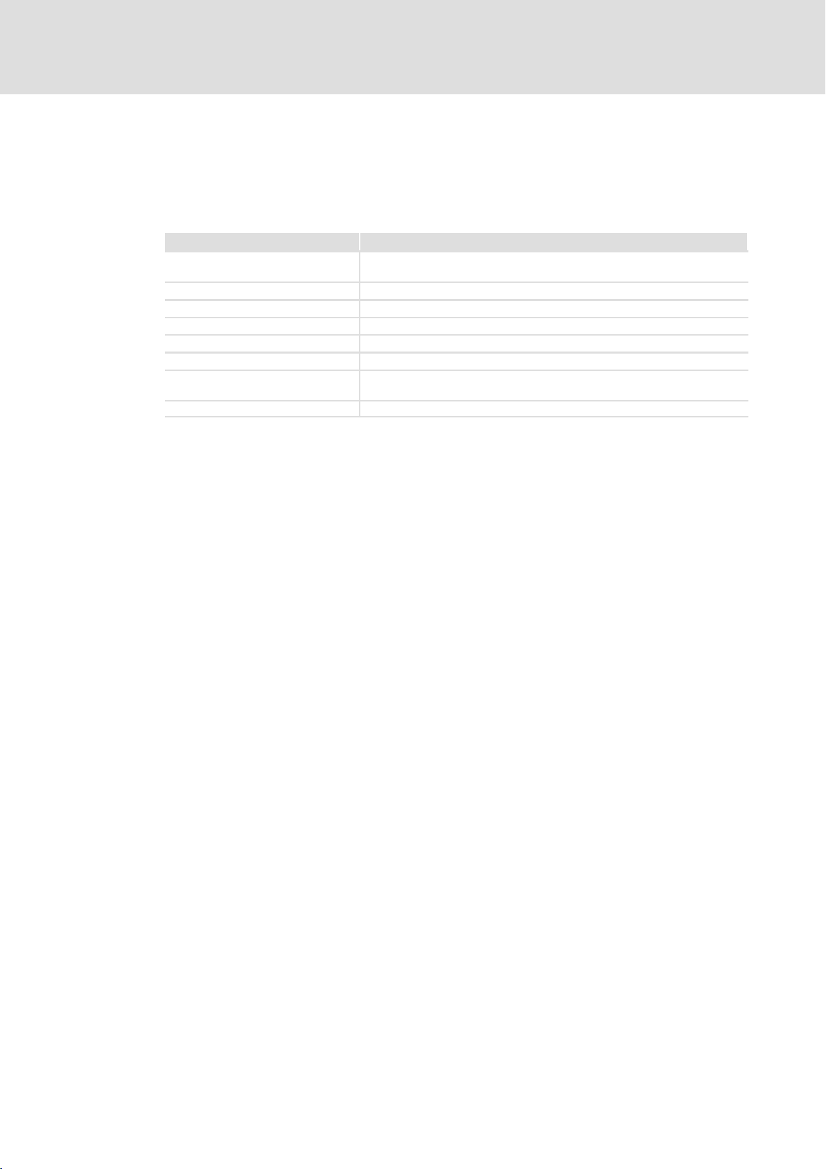
3 Technical data
3.1 Communication
Field Values
Communication profile
(DIN 19245 part 1 and part 3)
Communication medium RS485
Drive profile PROFIdrive
Network topology Without repeater: line / with repeaters: line or tree
PROFIBUS−DP device Slave
Baud rate [kbps] 9.6 ... 12000
Maximum cable length per bus
segment
Bus connection X4.1, X4.2 9−pin Sub−D socket (931E), 5−pin M12 connector (931K)
Profibus DP
1200 m (depending on baud rate and cable type)
10
l
KHB 13.0004−EN 2.1
Page 11

4 Electrical installation
4.1 Wiring
Basic wiring of the PROFIBUS
0
931x 931x 931x
X4.1/X4.2 X4.1/X4.2 X4.1/X4.2
111
£ 1200 m
Fig. 1 Basic wiring
Electrical installation
Wiring
4
931e_037
Element Note
0 Control system E.g. PC or PLC with PROFIBUS−DP master interface module
1 Bus cable Adapt baud rate to bus cable length
931X PROFIBUS slave Appropriate standard device
) Note!
When using a repeater, up to 125 stations can communicate via PROFIBUS.
EMC−compliant wiring
For wiring according to EMC requirements, please observe the following points:
) Note!
ƒ Separate control cables from motor cables.
ƒ Connect control/data cable shields correctly:
– On both sides for cables with digital signals.
ƒ Observe the information on wiring according to EMC guidelines given in the
documentation for the standard device.
Wiring procedure
1. Do not change the bus topology, i.e. do not use stubs.
KHB 13.0004−EN 2.1
2. Observe wiring notes given in the documentation for the control system.
3. Only use cables that comply with the listed specifications.
4. Activate bus terminating resistors at the first and last physical station.
When using sub plugs Lenze recommends to use sub−D plugs with internal series
inductance (110 nH).
l
11
Page 12

4
Electrical installation
Wiring
Number of bus stations
M
RR
SS S S S
123
2133PFB004
Segment Master (M) Slave (S) Repeater (R)
1 1
2
2 − 30 1
3 − 30 1
31
30
−
−
I Tip!
Repeaters do not have a station address but in the calculation of the
maximum number of stations they reduce the number of stations by 1 on
each side of the segment.
Repeaters can be used to build up line and tree topologies. In this case, the
maximum total bus system expansion depends on
ƒ the baud rate used
ƒ the number of repeaters used
12
l
KHB 13.0004−EN 2.1
Page 13
Electrical installation
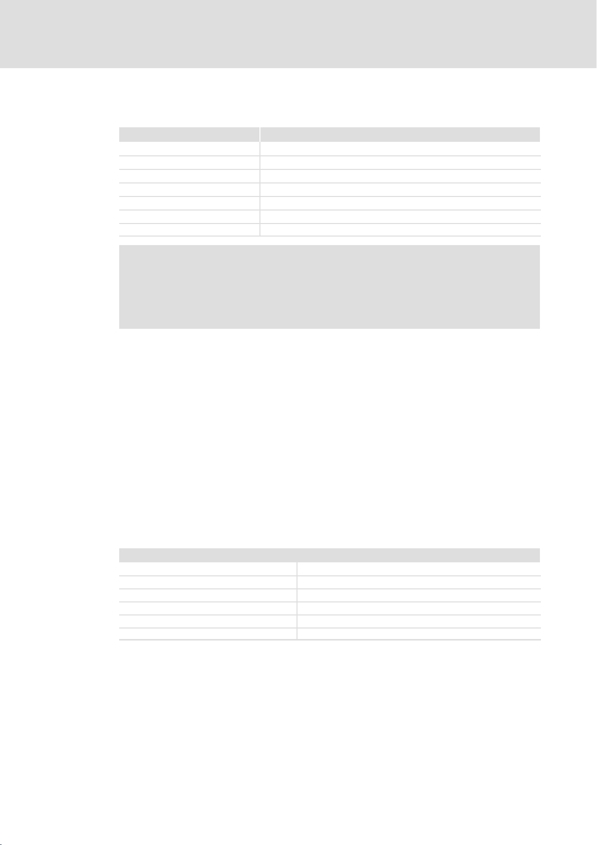
Baud rates
Baud rate [kbps] Length of the transmission cable [m]
9.6 ... 93.75 1200
187.5 1000
500 400
1500 200
3000 100
6000 100
12000 100
) Note!
ƒ The baud rate depends on the data volume, cycle time and number of bus
stations.
ƒ The baud rate selected should be as low as possible. The lower the baud
rate, the more insensitive the PROFIBUS is to parasitic coupling.
4
Wiring
I Tip!
For high baud rates, we recommend to consider the application of optical
fibres.
Advantages of optical fibres:
ƒ External electromagnetic interferences have no effects on the transmission
path.
ƒ Bus lengths of several kilometres are also possible with higher baud rates.
The bus length is
– independent of the baud rate.
– depend on the optical fibre used.
Specification of the transmission cable
Please follow the specifications of the PROFIBUS user organisation (PUO) for signal cables:
Bus cable specification
Specific resistance 135 − 165 W/km, (f = 3 − 20 MHz)
Capacitance per unit length £ 30 nF/km
Loop resistance < 110 W/km
Core diameter > 0.64 mm
Core cross−section > 0.34 mm
Cores Double twisted, insulated and shielded
2
KHB 13.0004−EN 2.1
l
13
Page 14
4
Electrical installation
Assignment of the interfaces
931E servo inverter
4.2 Assignment of the interfaces
4.2.1 931E servo inverter
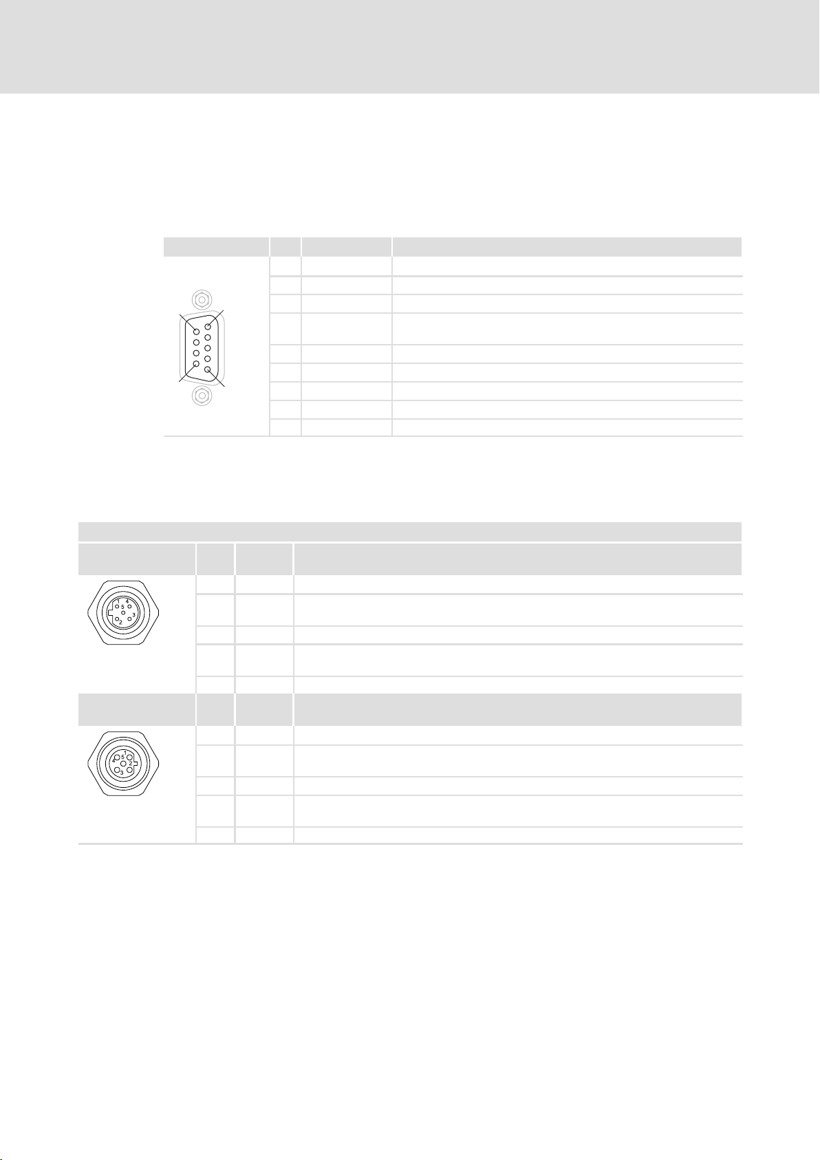
The controller is connected to the PROFIBUS via the 9−pin Sub−D socket X4.1/X4.2.
View Pin Designation Explanation
1 − −
2 − −
9
6
5
1
3 RxD/TxD−P Data line B (received/transmitted data plus)
4 RTS Request to send
5 M5V2 Data reference potential (ground to 5V)
6 P5V2 5 V DC / 30 mA (bus termination)
7 − −
8 RxD/TxD−N Data line A (received/transmitted data minus)
9 − −
4.2.2 931K servo inverter
The controller is connected to the PROFIBUS via the M12 connector X4.1/X4.2.
(received/transmitted data, no differential signal)
X4.1 / X4.2 PROFIBUS
Input contact pattern Pin
Output contact
pattern
Signal Specification
no.
1 n. c. Not assigned
2 RxD/TxD−NReceive / Transmit data −N (A line)
3 DGND Data Ground (reference potential to VP)
4 RxD/TxD−PReceive / Transmit data −plus (B line)
5 Shield Shield
Pin
Signal Specification
no.
1 VP Power supply plus (5V)
2 RxD/TxD−NReceive / Transmit data −N (A line)
3 DGND Data Ground (reference potential to VP)
4 RxD/TxD−PReceive / Transmit data −plus (B line)
5 Shield Shield
14
l
KHB 13.0004−EN 2.1
Page 15
5 PROFIBUS communication
5.1 The data telegram
The controller supports the communication protocol DP in the power section DP−V0. The
controller and the PLC communicate via receive telegram and response telegram. Enter
parameter numbers (PNU) in these telegrams to address objects of the drive (e.g. process
data and parameter data). Telegrams are transmitted cyclically. The telegram length
depends on the settings of the telegram editor in the SDC.
ƒ Receive telegrams contain output data which is transmitted from the PLC (master)
to the controller (slave).
ƒ Response telegrams contain input data which is transmitted from the
controller (slave) to the PLC (master).
5.1.1 Structure of the receive message
PROFIBUS communication
The data telegram
Structure of the receive message
5
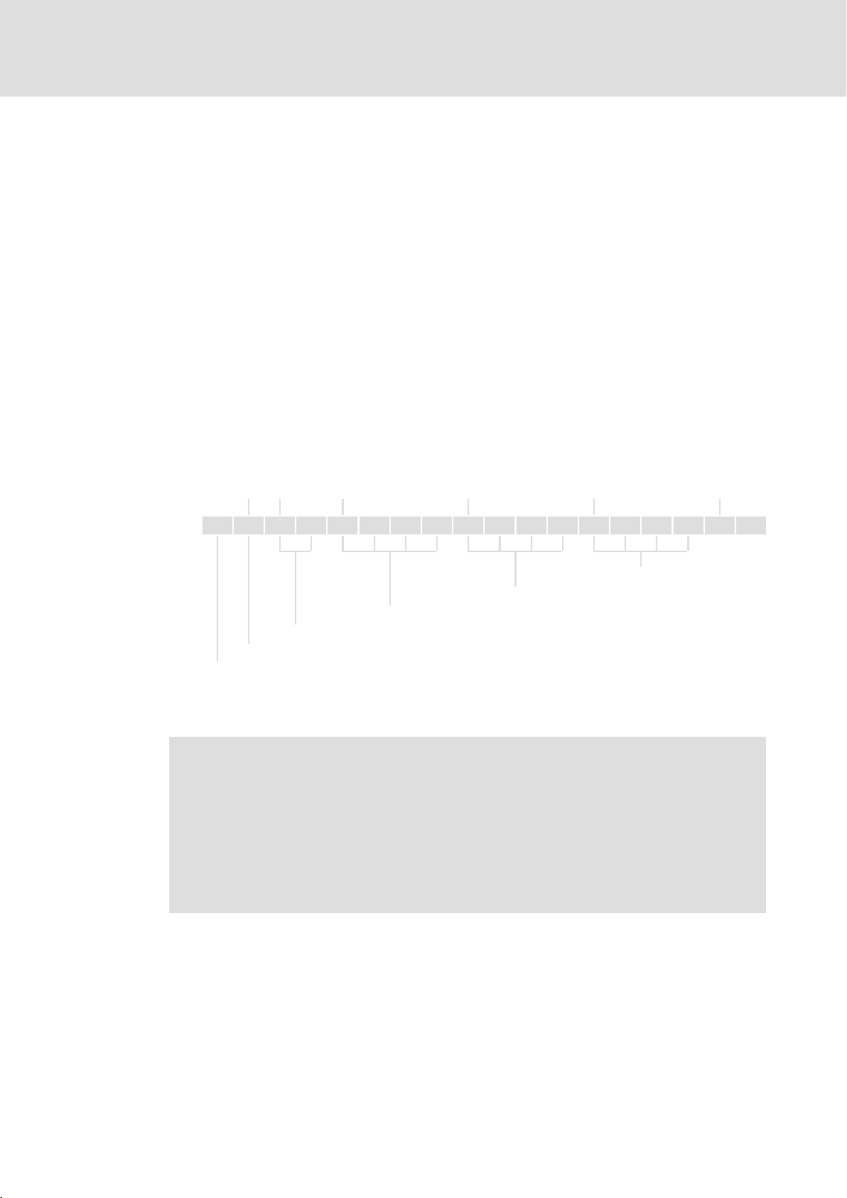
ADR = 1 ADR = 2 ADR = 4 ADR = 8 ADR = 12 ADR = 16
Byte 0 1 2 3 4 5 6 7 8 9 10 11 12 13 14 15 ... ...
Data 3rd PNU
Data 2nd PNU
Data 1st PNU
Control word 1 (PNU 967) (^ 54)
Mandatory wildcard (PNU 2010.0)
Telegram identifier (not changeable). Selecting the receive message in the telegram editor automatically
sets the operating mode:
l Receive message 0: "positioning" mode (value of byte 0: E0
l Receive message 1: "speed control" mode (value of byte 0: E1
)
h
)
h
) Note!
ƒ To enable the PLC to receive the process data from the controller, you have
to assign the corresponding response message to the receive message in
"SDC". (¶ 24)
ƒ In the PLC you have to enter the identifier in byte 0 of the receive message.
The identifier sets the operating mode of the controller.
: speed control mode
–E1
h
: positioning mode
–E0
h
KHB 13.0004−EN 2.1
l
15
Page 16
5
PROFIBUS communication
The data telegram
Structure of the response message
5.1.2 Structure of the response message
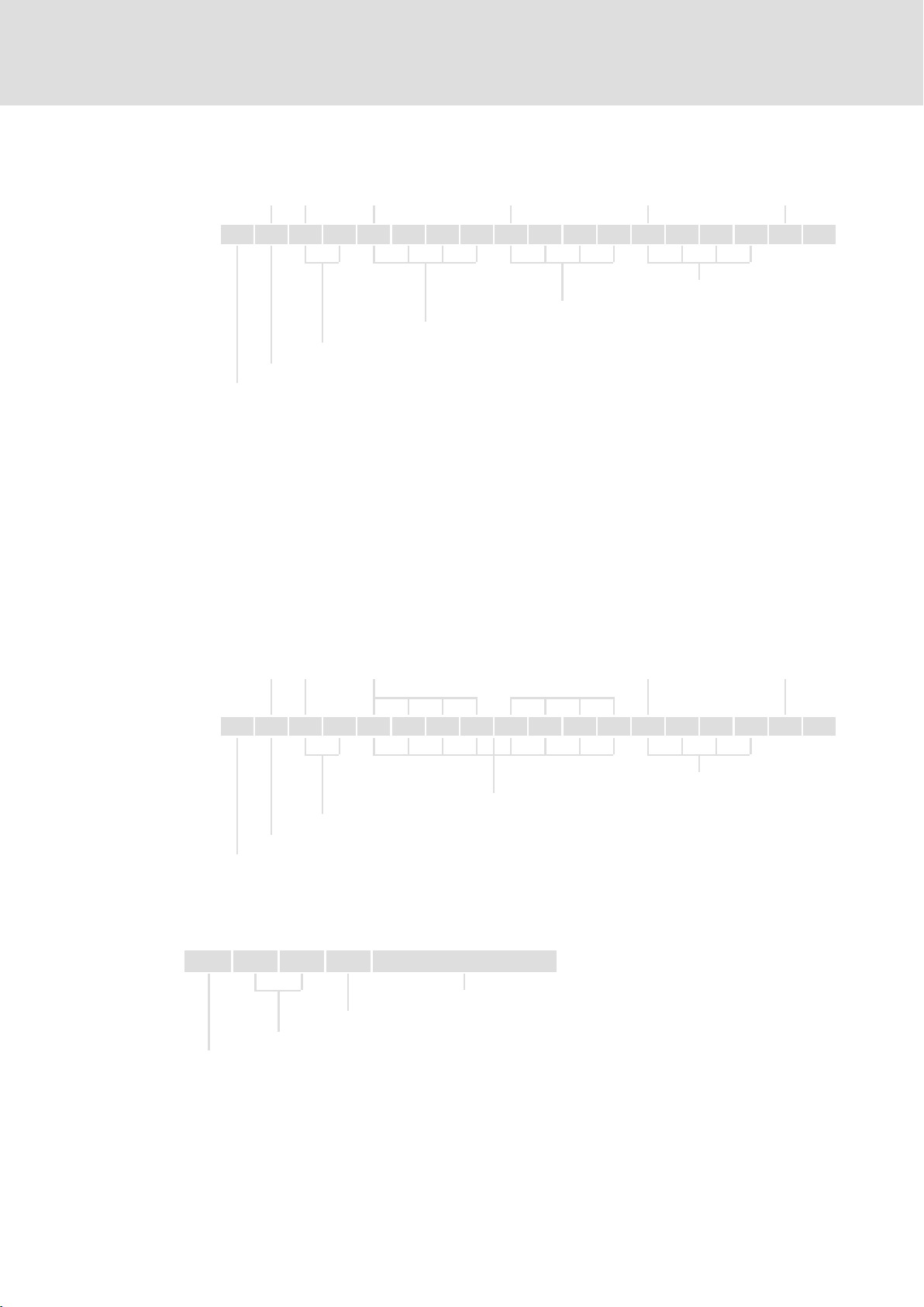
ADR = 1 ADR = 2 ADR = 4 ADR = 8 ADR = 12 ADR = 16
Byte 0 1 2 3 4 5 6 7 8 9 10 11 12 13 14 15 ... ...
Data 2nd PNU
Data 1st PNU
Status word 1 (PNU 968)
Mandatory wildcard (PNU 2010.0)
Telegram identifier (not changeable). In the telegram editor the corresponding response message has to
be assigned to the receive message:
l Response message 0: "positioning" mode (value of byte 0: F0
l Response message 1: "speed control" mode (value of byte 0: F1
)
h
)
h
5.1.3 Structure of the receive and response message with PKW mechanism
Data 3rd PNU
The PKW mechanism (PKW = parameter identifier value) enables a variable read/write
access to the parameters of the controller with a defined telegram structure.
ƒ Use the PNU 2000 for the PKW mechanism.
Receive message
The PNU 2000 can be entered in the telegram editor, for instance under address 4.
ADR = 1 ADR = 2 ADR = 4 ADR = 12 ADR = 16
1st DWORD 2nd DWORD
Byte 0 1 2 3 4 5 6 7 8 9 10 11 12 13 14 15 ... ...
Data 2nd PNU
PNU 2000
Control word 1 (PNU 967) (^ 54)
Mandatory wildcard (PNU 2010.0)
Telegram identifier
ƒ Structure of PNU 2000:
(two data double words (2 × 4 bytes))
Byte 0 Byte 1 Byte 2 Byte 3 Byte 4 7
16
PNU to be accessed by the master
Identifier:
l Read access: 41
l Write access: 42
l No access: 00
h
Subindex of PNU
h
h
Parameter value
l
KHB 13.0004−EN 2.1
Page 17

PROFIBUS communication
The data telegram
Structure of the receive and response message with PKW mechanism
Response message
The PNU 2000 must be entered under the same address as in the receive message.
ADR = 1 ADR = 2 ADR = 4 ADR = 12 ADR = 16
1st DWORD 2nd DWORD
Byte 0 1 2 3 4 5 6 7 8 9 10 11 12 13 14 15 ... ...
Data 2nd PNU
PNU 2000
Status word 1 (PNU 968)
Mandatory wildcard (PNU 2010.0)
Telegram identifier
ƒ Structure of PNU 2000:
(two data double words (2 × 4 bytes))
Byte 0 Byte 1 Byte 2 Byte 3 Byte 4 7
5
PNU requested by the master
Identifier:
l Write access: 42
) Note!
ƒ The PNU 2000 must be entered under the same address in the receive
message and in the corresponding response message!
ƒ For reasons relating to the address register of the master’s CPU (see
documentation for the master), we recommend to use variables of the type
"double word" for the telegram.
If the telegram is generated byte by byte, a shift in the data telegram may
result which causes transmission errors.
ƒ The transmission of a parameter is not acknowledged by the controller.
Subindex of PNU
h
Parameter value
KHB 13.0004−EN 2.1
l
17
Page 18
5
PROFIBUS communication
Consistent parameter data
Structure of the receive and response message with PKW mechanism
5.2 Consistent parameter data
In the PROFIBUS communication system, a permanent data exchange takes place between
the master computer (CPU + PROFIBUS master) and the slave.
The PROFIBUS master and the CPU (central processing unit) of the master computer access
a common storage medium for this purpose − the dual port memory (DPM).
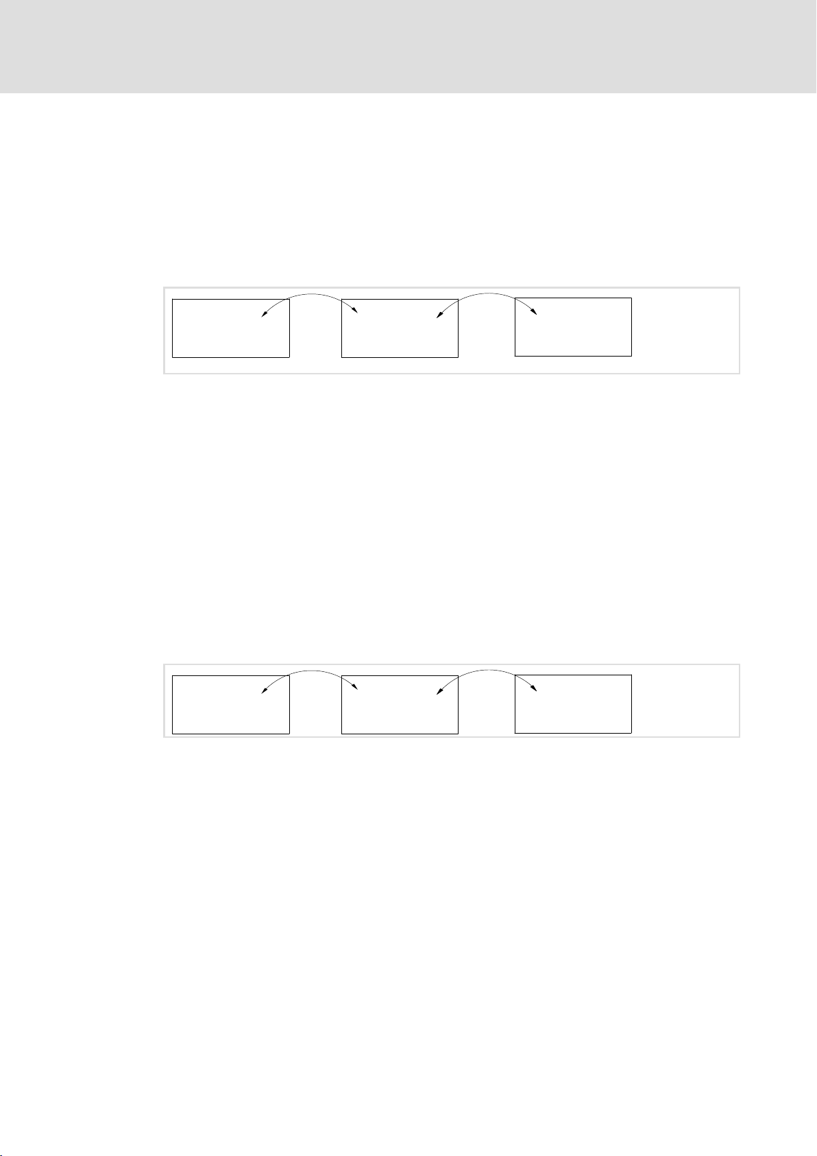
The DPM enables a data exchange into both directions (read/write):
Central Processing
Unit (CPU)
ó
Without any further data organisation, a slower write action of the PROFIBUS master
might be overtaken by a faster read action of the CPU within a cycle.
To prevent this from happening, the parameter data to be transferred must be marked as
"consistent".
Dual Port Memory
(DPM)
ó
PROFIBUS Master
Data communication with existing consistency
With consistency either "read" or "write" is possible in the data memory if master and CPU
have access at the same time:
ƒ The PROFIBUS master only transfers the data as a complete data record.
ƒ The CPU can only access completely updated data records.
ƒ The PROFIBUS master cannot read or write data as long as the CPU accesses
consistent data.
The result is shown in the following example:
01
ó
Central Processing
Unit (CPU)
CPU wants to read!
0
PROFIBUS master wants to write at the same time!
1
1. Due to the fact that the PROFIBUS master can only write if the CPU does not read, the
2. The PROFIBUS master only writes complete data records into the DPM.
Dual Port Memory
(DPM)
PROFIBUS master has to wait until the CPU has read all of the data.
ó
Configuration of consistent data
Consistency is achieved by configuring the PROFIBUS master accordingly. Use the
corresponding instructions of your configuration software for this purpose.
PROFIBUS Master
18
l
KHB 13.0004−EN 2.1
Page 19

6 Commissioning
6.1 Important notes
Before you switch on the controller for the first time in the PROFIBUS−DP network, check
ƒ the entire wiring for completeness, short circuit, and earth fault,
ƒ and whether the bus system is terminated by terminating resistors at the first and
last bus station.
6.2 Initial switch−on
) Note!
Keep to the switch−on sequence!
Commissioning
Important notes
6
Step Procedure See
A Settings on the controller (slave)
l You need a PC and the »Small Drives Control (SDC)« PC software
1. Switch on the controller Software manual for
2. Establish RS232 communication between the PC and the controller
3. Set the node address
l Selection of the node address via »Small Drives Control (SDC)« ^ 21
l Selection of the node address via the digital inputs DIN0 ... DIN5 ^ 22
4. Define the parameter numbers (PNU) in the telegram editor ^ 24
5. Save the settings in the parameter set of the controller
B Configuration of the control system (master)
1. Switch on the control system Documentation for
2. Install the device data base file (*.GSE) ^ 27
3. Enter the slave addresses
4. Configure the input data and output data according to the settings in the
telegram editor (project creation). The data width depends on the entries in the
telegram editor
5. Save, compile and transfer the project Documentation for
C Activation of communication
1. Activate communication on the master Documentation for
2. Activate communication on the slave ^ 21
D Running the controller up via the PROFIdrive state machine
1. "Speed control" mode ^ 28
2. "Positioning" mode ^ 30
The drive is controlled according to the setpoints specified by the PLC and the operating mode set.
the controller
the master
^ 24
the master
the master
KHB 13.0004−EN 2.1
l 19
Page 20

6
6.3 Settings on the controller (slave)
Commissioning
Settings on the controller (slave)
) Note!
The controller parameters are set using the »Small Drives Control (SDC)« PC
software.
ƒ Establish an RS232 connection for communication between the PC and the
controller. For a detailed description please refer to the controller’s software
manual.
ƒ Save all settings in the parameter set of the controller using the command
File W Parameter set W Save parameter set (flash) to prevent the settings
from getting lost in the case of a reset or mains switching.
l 20
KHB 13.0004−EN 2.1
Page 21
6.3.1 Node address setting
Selecting the node address via »Small Drives Control (SDC)«
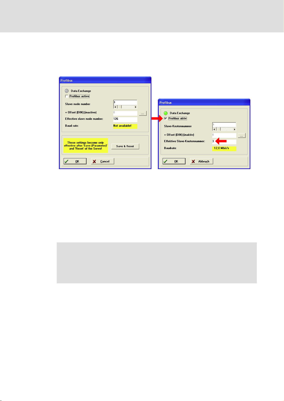
1. Open the Parameters W Fieldbus W Profibus... W Operating parameters... menu.
Commissioning
Settings on the controller (slave)
Node address setting
6
931E_020, 931E_21
2. Enter the desired node address for the controller in the Slave node number input
box.
3. Tick the Profibus active check box.
– If the check box is enabled, the Slave node number input box is disabled.
4. Click on the Save & Reset button to save the settings.
– After saving, the assigned node address is displayed in the Effective slave node
number box.
5. Click on the OK button.
) Note!
The dialog box displays that the communication between master and slave
has been established successfully:
ƒ The Data Exchange box is lit green.
ƒ The baud rate set on the master is displayed in the Baud rate box.
KHB 13.0004−EN 2.1
l 21
Page 22
6
Commissioning
Settings on the controller (slave)
Node address setting
Selecting the node address via the digital inputs DIN0 ... DIN5
You assign the node address to the controller by adding to the preset slave node number
an offset via DIN0 ... DIN5.
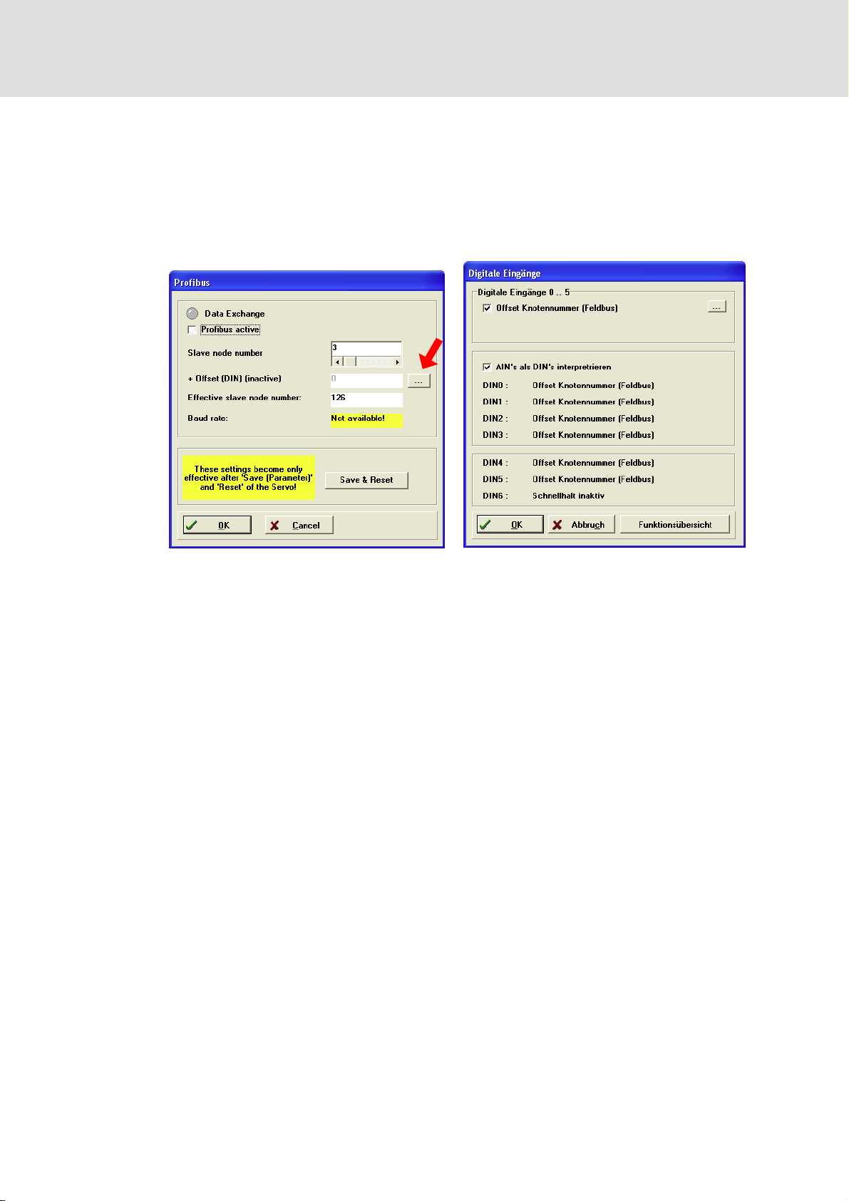
1. Open the Parameters W Fieldbus W Profibus... W Operating parameters... menu.
931E_020, 931E_22
2. Enter the desired value in the Slave node number input box.
3. Click on the + Offset (DIN) (inactive) button (see arrow in the screenshot of the
"Profibus" dialog box).
– The Digital inputs dialog box opens.
4. Tick the Offset node number (field bus) check box.
– Tick the AIN’s used as DIN’s check box (if necessary) to use DIN0 ... DIN3 as well for
the offset.
– Adjustable offset: 0 ... 63 with DIN0 ... DIN5 or 16, 32, 48 with DIN4, DIN5
– Click on the OK button.
5. Set the digital inputs DINx for the desired offset.
Calculation of the offset:
Offset = DIN0 × 2
0
+ DIN1 × 21 + DIN2 × 22 + DIN3 × 23 + DIN4 × 24 + DIN5 × 2
5
Example:
The node address of the controller is to be "35". In the Slave node number input box "3"
is entered. So the offset must be "32":
Offset = DIN0 × 20+ DIN1 × 21+ DIN2 × 22+ DIN3 × 23+ DIN4 × 24+ DIN5 × 2
32 = 0 × 20+0× 21+0× 22+0× 23+0× 24+ 1 × 2
5
5
6. Click on the Save & Reset button to save the settings.
– Important: After clicking on the button, the states of the digital inputs are read
once. The offset is added to the slave node number. Subsequent changes have no
effect.
– After saving, the assigned node address is displayed in the Effective slave node
number box.
l 22
KHB 13.0004−EN 2.1
Page 23

7. Click on the OK button.
) Note!
The dialog box displays that the communication between master and slave
has been established successfully:
ƒ The Data Exchange box is lit green.
ƒ The baud rate set on the master is displayed in the Baud rate box.
Commissioning
Settings on the controller (slave)
Node address setting
6
931E_23
KHB 13.0004−EN 2.1
l 23
Page 24
6
Commissioning
Settings on the controller (slave)
Definition of parameter numbers (PNU) in the telegram editor
6.3.2 Definition of parameter numbers (PNU) in the telegram editor
ƒ Parameter numbers (PNU) can be used to address drive objects (e.g. process and
parameter data).
– Parameter numbers can comprise several subindexes under which objects are
represented. When defining the PNU, the respective subindex must be defined as
well.
ƒ With the telegram editor you can define all PNUs required for the application. The
PNUs are stored in the controller.
– Define the PNUs before activating communication to the master.
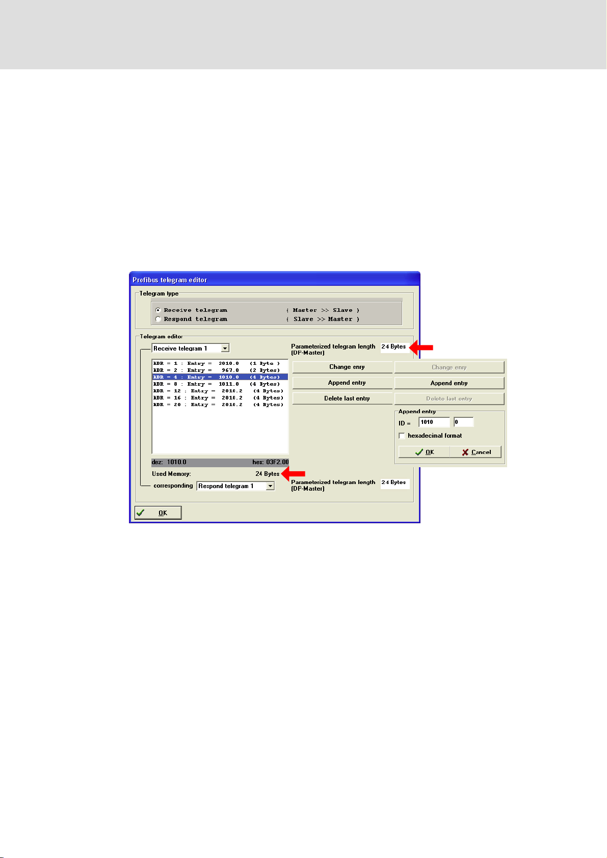
1. Open the Parameters W Fieldbus W Profibus... W Profibus telegram editor... menu.
931E_024
2. Select "Receive telegram" in the Telegram type box.
– Each telegram may contain a maximum of 10 entries.
– The length of the telegram must not exceed 32 bytes.
3. Select the receive telegram 0 or 1 and the corresponding respond telegram in the
Telegram editor box.
– Use the receive and response message 0 for the "positioning" mode.
– Use the receive and response message 1 for the "speed control" mode.
– Byte 0 (telegram identifier, not visible) and the entries for byte 1 (ADR − 1) and
byte 2 / byte 3 (ADR − 2) are necessary for faultless communication. Do not change
these entries.
l 24
KHB 13.0004−EN 2.1
Page 25

Commissioning
Settings on the controller (slave)
Definition of parameter numbers (PNU) in the telegram editor
) Note!
ƒ If the response message does not correspond to the receive message, the
master receives incorrect data from the controller.
ƒ In the PLC you have to enter the identifier in byte 0 of the receive message.
The identifier sets the operating mode of the controller.
–E1
: speed control mode
h
: positioning mode
–E0
h
4. Click on the Append entry button to enter a PNU.
– If you want to enter the PNU in hexadecimal notation, activate the hexadecimal
format in the Append entry box.
– If you want to change a PNU, select the PNU and click on the Change entry button.
– If you want to delete the PNU entered last, click on the Delete last entry button.
) Note!
ƒ If necessary, enter PNU 2010 as a wildcard to make the telegram length
match the parameterised telegram length of the master.
ƒ Check that the parameterised telegram length corresponds to the memory
allocation (see arrows in the screenshot of the "Profibus telegram editor"
dialog box).
6
KHB 13.0004−EN 2.1
l 25
Page 26
6
Commissioning
Settings on the controller (slave)
Definition of parameter numbers (PNU) in the telegram editor
931E_025
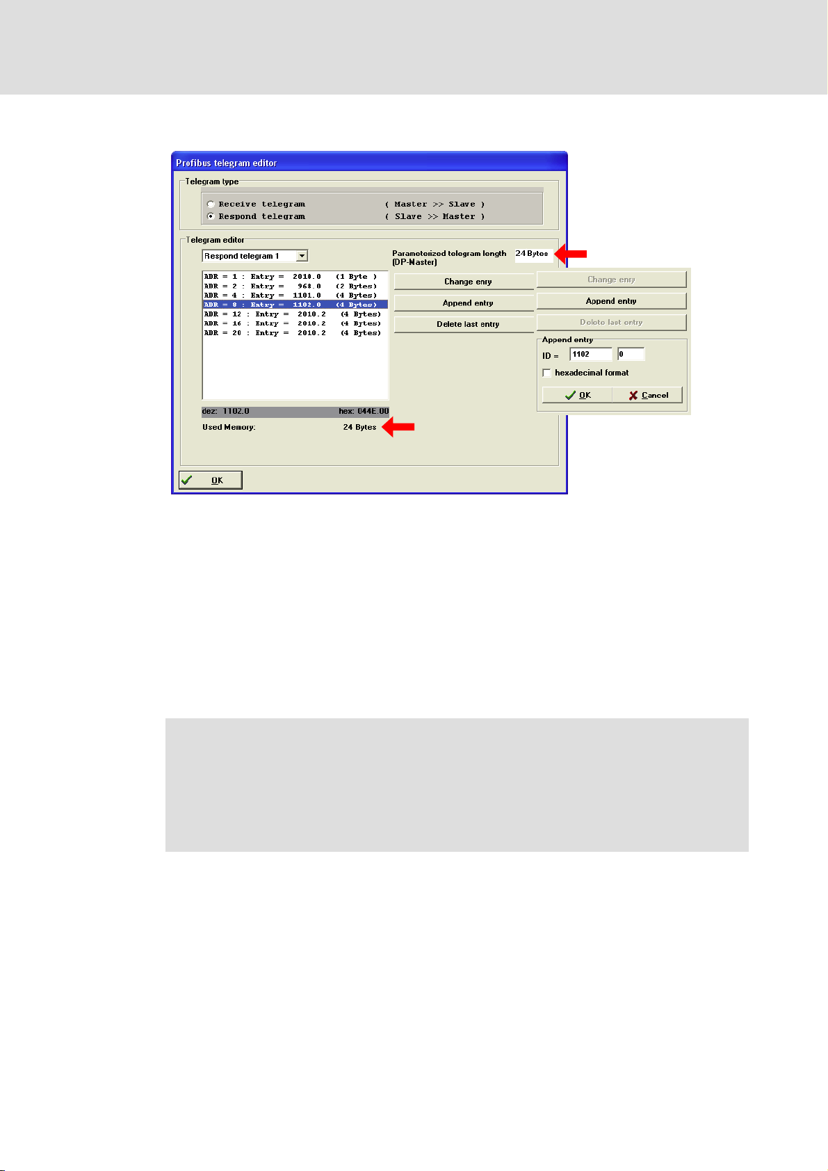
5. Select "Respond telegram" in the Telegram type field.
– Byte 0 (telegram identifier, not visible) and the entries for byte 1 (ADR − 1) and
byte 2 / byte 3 (ADR − 2) are necessary for faultless communication. Do not change
these entries.
6. Click on the Append entry button to enter a PNU.
– If you want to enter the PNU in hexadecimal notation, activate the hexadecimal
format in the Append entry box.
– If you want to change a PNU, select the PNU and click on the Change entry button.
– If you want to delete the PNU entered last, click on the Delete last entry button.
) Note!
ƒ If necessary, enter PNU 2010 as a wildcard to make the telegram length
match the parameterised telegram length of the master.
ƒ Check that the parameterised telegram length corresponds to the memory
allocation (see arrows in the screenshot of the "Profibus telegram editor"
dialog box).
l 26
KHB 13.0004−EN 2.1
Page 27

6.4 Control system configuration
The control system must be configured before communication with the controller is
possible.
Installing the device data base file (*.GSE)
For the configuration you have to install the device data base file "931E0A6D.GSE" on the
master.
1. Download the GSE file from the Internet.
– You can find the GSE file in the "Services & Downloads" area at
http://www.Lenze.com.
2. Install the GSE file.
– Installation notes are given in the documentation for the master and in the
documentation for the configuration tool.
Commissioning
Control system configuration
6
Creating a project
ƒ Please refer to the documentation for the configuration tool if you want to create a
project.
) Note!
Use of data consistency
ƒ We recommend to use exclusively configurations with consistency to avoid
data conflicts between the PROFIBUS−DP master and the CPU of the control
system.
– If the telegram has, for instance, a length of 8 bytes of data, the PLC must
be able to process the 8 bytes of data continuously (consistently).
ƒ Detailed description of consistency: (¶ 18)
ƒ Please note that the processing of consistent data varies between different
control systems. This must be considered in the configuration tool.
– It may be necessary to use system functions of the PLC to ensure the data
consistency.
– Please refer to the documentation for the PLC to find out which data
length can be processed consistently by the CPU.
KHB 13.0004−EN 2.1
l 27
Page 28
6
Commissioning
"Speed control" mode
Description
6.5 "Speed control" mode
6.5.1 Description
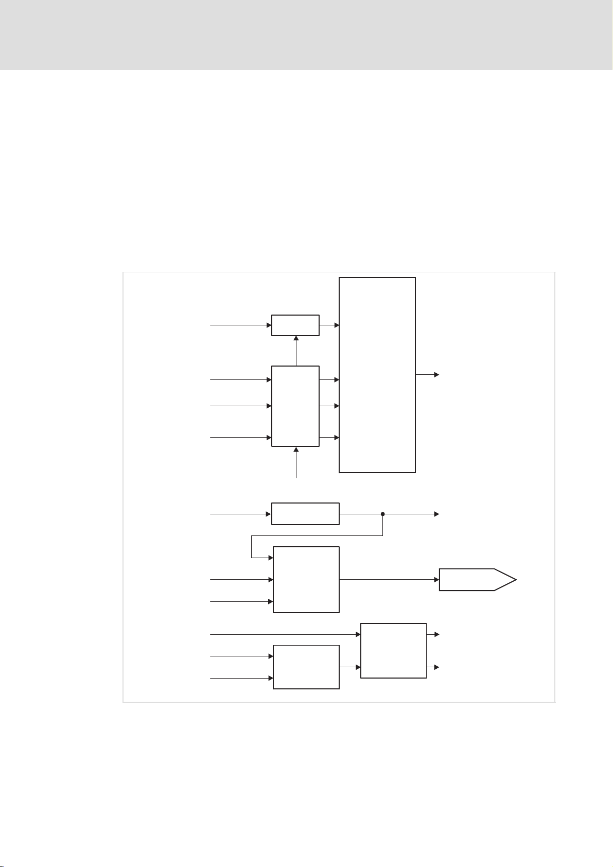
The following functions are available:
ƒ Setpoint generation via ramp generator (limit function)
ƒ Speed detection via angle encoder by differentiation
ƒ Speed control with appropriate input and output signals
ƒ Limitation of speed setpoint (via PROFIBUS or analog input)
ƒ Monitoring of actual speed (velocity controller)
Limit Function
target velocity
(PNU 1010)
acceleration velocity control
deceleration
velocity demand value ( )2
(PNU 1011.0)
velocity control
(PNU 1011.1)
quick stop
deceleration ( )0
position actual value
(PNU 1100.0)
velocity control
parameter set ( )0
[speed units]
velocity encoder factor ( )1
[acceleration units]
[acceleration units]
[acceleration units]
acceleration factor ( )1
Multiplier
Multiplier
Differentiation
d/dt
Velocity
Controller
Profile Velocity
Profile Acceleration
Profile Deceleration
Quick Stop Deceleration
[inc]
velocity demand value ( )2
velocity actual value
(PNU 1101.0)
control effort
velocity window time ( )2
velocity actual value
(PNU 1101.0)
velocity window
Window
Comparator
Fig. 2 Signal routing for the "speed control" mode
0 Function can be parameterised via SDC
1 Physical unit, can be parameterised via SDC
2 Internal signal
l 28
Timer
status word 1
(PNU 968.0, Bit 8,
velocity = 0)
status word 1
(PNU 968.0, Bit 10,
velocity reached)
KHB 13.0004−EN 2.1
931e_030
Page 29

Commissioning
"Speed control" mode
Commissioning with PROFIdrive
6
6.5.2 Commissioning with PROFIdrive
) Note!
ƒ The bit assignment of the control word 1 and the status word 1 is described
in the chapter "Device control". (¶ 54)
ƒ To enable the PLC to control the controller via PROFIBUS, bit 10 of the
control word 1 must be set statically. When the communication self−test has
been completed successfully, bit 9 of the status word 1 is set.
Description PNU SubindexLength Parameter
A Running the controller up via the state machine
1. Control word 1 (WO)
SWITCHING_ON_INHIBITED
2. Status word 1 (RO)
SWITCHING_ON_INHIBITED
3. Control word 1 (WO)
READY_FOR_SWITCH_ON
4. Status word 1 (RO)
READY_FOR_SWITCH_ON
5. Control word 1 (WO)
Enable operation
6. Status word 1 (RO)
Operation
B Control operation
7. Selection of setpoints
Note: Controller parameters cannot be
changed via PNUs.
UNIT16 Bit 3 Bit 2 Bit 1 Bit 0
967 0 16 0 1 1 0
968 0 16 0 0 0 1
967 0 16 0 1 1 1
968 0 16 0 0 1 1
967 0 16 1 1 1 1
968 0 16 0 1 1 1
KHB 13.0004−EN 2.1
l 29
Page 30

6
Commissioning
"Positioning" mode
PNUs for parameter setting
6.5.3 PNUs for parameter setting
PNU Name
1010 0 Target Velocity 0 0 {1 rpm} 6000
1011 Acceleration for
1101 0 Velocity Actual
1102 0 Current Actual
Velocity Control
0 Acceleration
Velocity Control
1 Deceleration
Velocity Control
2 All Accelerations
Velocity Control
Value
Value
Possible settings
Lenze Selection Description
10000 0 {1 rpm/s} 20000 Acceleration, the value set is
10000 0 {1 rpm/s} 20000 Deceleration, the value set is
10000 0 {1 rpm/s} 20000 Acceleration and
{1 rpm}
{1 }
Characteristics
INT32 RW
Selection of the speed
setpoint.
l If the speed control mode
is selected in SDC, the
selector under "setpoint
selection" changes over if
required: AIN0/1, Profibus
or RS232
UINT32 RW
Setting the acceleration and
deceleration for the speed
control mode
valid for both directions of
rotation
l Reads out only the actual
value for the positive
direction of rotation
valid for both directions of
rotation
l Reads out only the actual
value for the positive
direction of rotation
deceleration, the value set is
valid for both directions of
rotation
l Writes the value set to
PNU 1011, subindexes 0
and 1
l Reads out the actual value
for the positive direction
of rotation under
PNU 1011, subindex 0
INT32 RO
Actual speed value. The value
is scaled to the physical unit
set for PROFIBUS.
INT32 RO
Actual value of active current.
The value refers to the rated
motor current.
6.6 "Positioning" mode
l 30
KHB 13.0004−EN 2.1
Page 31
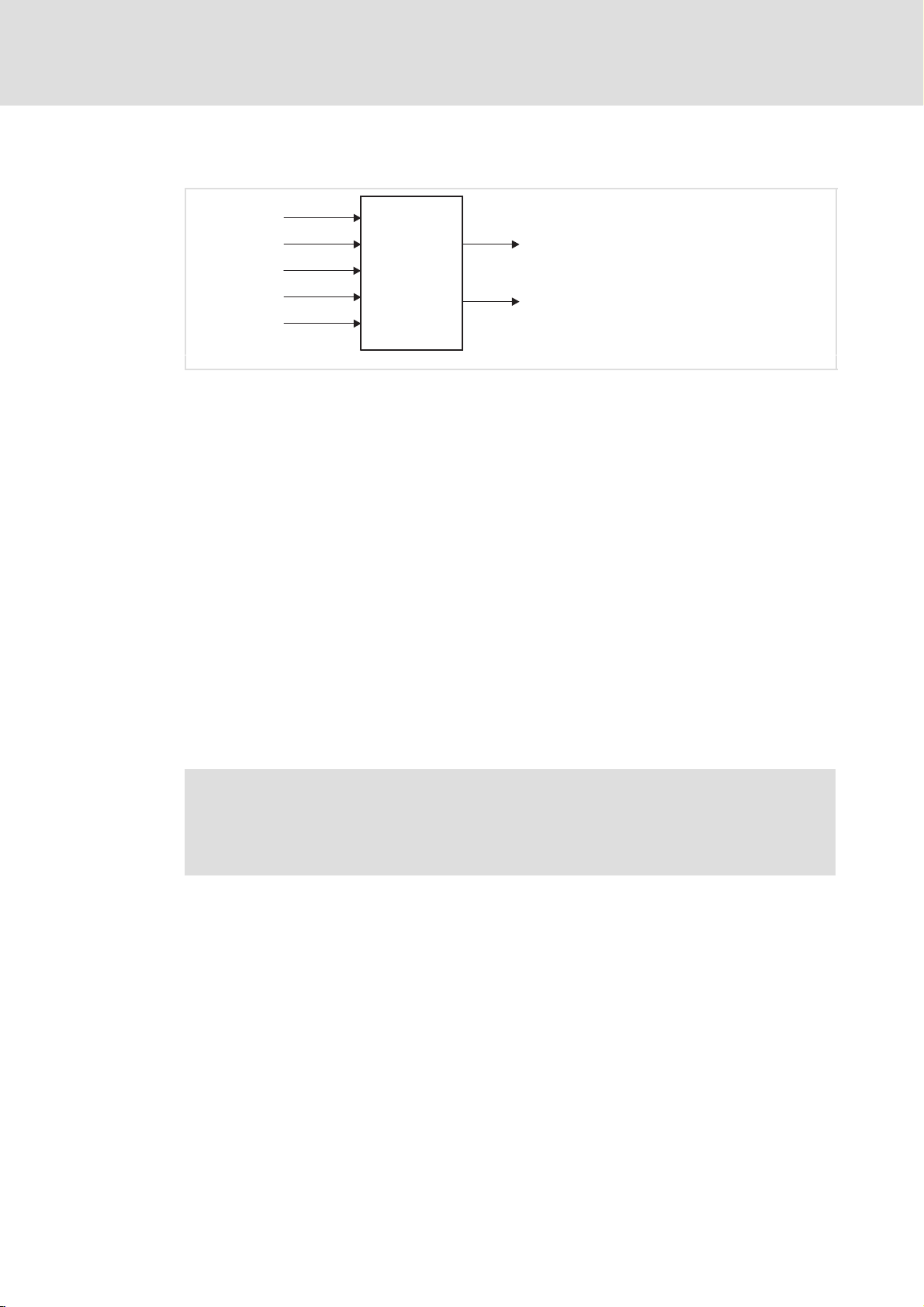
6.6.1 Setting of homing
Commissioning
"Positioning" mode
Setting of homing
6
control word 1
(PNU 967.0, Bit 11)
home offset
(PNU 1051.0)
homing method
(PNU 1050.0)
home speed ( )0
home acceleration ( )0
Fig. 3 Signal routing for homing
0 Function can be parameterised via SDC
1 Internal signal
Homing
status word 1
(PNU 968.0 Bit 11)
position demand value ( )1
Adjustment
ƒ Homing speed
– First the drive searches for the limit switch using the search speed. For
determining the position of the switching edge exactly, the drive changes to the
creep speed. Both speeds are set in SDC.
ƒ Acceleration
– The acceleration is set in SDC.
ƒ Homing mode
– A description of the different homing methods is given in the software manual of
the controller.
931e_028
ƒ Shifting of the zero position
– Via PNU 1051.0 the zero position of the drive can be shifted. The value under
PNU 1051.0 is added to the value of the homing point (e.g. limit switch position).
) Note!
Traversing to the zero position is not part of the homing run. If the controller
knows all parameters required (e.g. the position of the zero pulse), no physical
movement is executed.
KHB 13.0004−EN 2.1
l 31
Page 32

6
Commissioning
"Positioning" mode
Positioning
6.6.2 Positioning
position factor
polarity()()11
Multiplier
target_postion
(PNU 1001.0)
[position units]
home offset (PNU 1051.0)
Limit
Function
2
position set number (PNU 1000)
profile velocity (PNU 1001.1)
acceleration positioning (PNU 1001.3)
deceleration
accelerationsall
Fig. 4 Signal routing for the "positioning" mode
positioning (PNU 1001.4)
positioning (PNU 1001.5)
0 Internal signal
1 Physical unit, can be parameterised via SDC
2 Trajectory generator
3 Position controller
Quick Stop
position profile type
(PNU 1003.0)
Trajectory
Generator
position demand value ( )0
[inc]
ƒ The target position is transferred to the trajectory generator via PNU 1001.0. The
trajectory generator generates the position setpoint for the position controller.
Trajectory generator and position controller can be set independently of each other.
3
Position
Control
Function
control effort ( )0
931e_032
l 32
KHB 13.0004−EN 2.1
Page 33
Commissioning
"Positioning" mode
Positioning
Adjustment
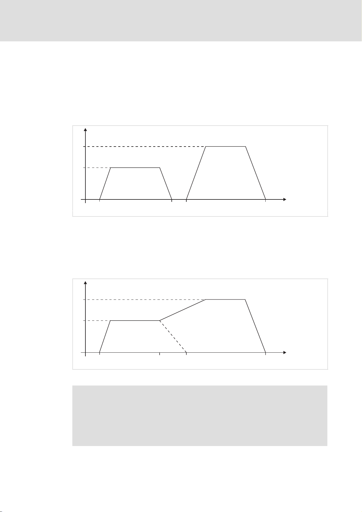
ƒ Simple travel task
– Select position data set (0 63) under PNU 1002. (¶ 35)
– Activation: Control word 1, set bit 6 from 0 ® 1.
– The controller stops when the target position has been reached. Bit 10 of status
word 1 is used to signal the reaching of the target position to the master.
v
v
2
v
1
6
t
t
0
Fig. 5 Simple travel task
ƒ Sequence of travel tasks
t
t
1
2
t
3
– Select position data set (0 63) under PNU 1002. (¶ 35)
– Activation: Control word 1, set bit 13 = 0.
– When a target position has been reached, the controller immediately starts to
approach the next target position.
v
v
2
v
1
t
t
0
Fig. 6 Sequence of travel tasks
t
2
t
1
t
3
931e_407
931e_408
KHB 13.0004−EN 2.1
) Note!
It is possible to interrupt the running travel task and immediately start the
next travel task:
ƒ Select PROFIBUS position data set (68) under PNU 1002. (¶ 36)
ƒ Activation: Control word 1, set bit 13 = 1.
– Interruption of the positioning process. Start of next travel task.
l 33
Page 34

6
Commissioning
"Positioning" mode
Positioning
Transfer of travel task
1
Bit 10
t
1
(1) (2)
1
Bit 4
Control word 1
1
Bit 5
1
Bit 6
1
Bit 9
1
Bit 10
Status word 1
1
Bit 11
(0)
(3)
(4)
(5)
(6)
Fig. 7 Transfer of travel task to the controller
t(0) Status word 1, bit 11 = HIGH: home position is valid
t(1)−(2) Data transfer (acceleration, target position, speed) from master to corresponding
position data set (^ 32)
(PNU 1000 = 68: selection of PROFIBUS position data set)
t(3) Control word 1, bit 4 = HIGH: do not cancel travel task
t(4) Control word 1, bit 5 = HIGH: no intermediate stop
t(5) Control word 1, bit 6 = LOW−HIGH edge: activate travel task
t(6) Status word 1, bit 10 = HIGH: target position reached
t
t
t
t
t
t
t
931e_031
l 34
KHB 13.0004−EN 2.1
Page 35

Commissioning
"Positioning" mode
Static position data sets
6
6.6.3 Static position data sets
The settings (positioning, start delay, start during positioning) and the driving profile
(travelling speed, acceleration, time constant without jerk) of the position data sets 0 ... 63,
which can be parameterised with »Small Drives Control (SDC)«, are divided into four
groups (see software manual for the controller).
ƒ You can, for instance, select a travelling speed for the "Positioning 0 15" group
(position data sets 0 15). This also applies to the position data sets 16 31,
32 47 and 48 63.
ƒ The target positions 0 63 are parameterised in SDC. Only approaching/activating
of the target positions (PNU 1002.0 = 0 63) is controlled via PROFIBUS.
) Note!
Please observe that you have to jump between the groups if e.g. the travelling
speeds differ.
"Settings" tab sheet
ƒ Open the Parameters W Positioning W Destination parameters... menu.
ƒ All settings have to be made in SDC.
ƒ The driving profile is specified via PROFIBUS.
931E_33
KHB 13.0004−EN 2.1
l 35
Page 36
6
6.6.4 Dynamic position data set
Commissioning
"Positioning" mode
Dynamic position data set
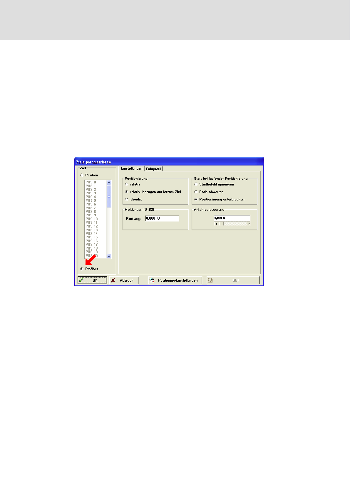
If the application requires positioning with different settings and driving profiles, use
dynamic positioning via position data set 68:
ƒ Selection of the driving profile via PROFIBUS.
ƒ Changing between absolute and relative positioning via control word 1.
ƒ Interruption of a running positioning task and approaching of a new target via a
start command.
"Settings" tab sheet
ƒ Open the Parameters W Positioning W Destination parameters... menu.
931e_34
ƒ Settings required in SDC:
– Messages (0..63) box (see software manual for the controller)
– Start delay (0..15) box (see software manual for the controller)
ƒ Control via PROFIBUS, control word 1:
– Bit 12 can be used to select between "relative" and "absolute" in the Positioning
(0..15) box.
– Bit 4 can be used to select "Ignore start command" in the Start during positioning
box and bit 13 to select "Wait for end of positioning run" or "Interrupt actual
positioning".
l 36
KHB 13.0004−EN 2.1
Page 37

6.6.5 Commissioning with PROFIdrive
) Note!
ƒ The bit assignment of the control word 1 and the status word 1 is described
in the chapter "Device control". (¶ 54)
ƒ To enable the PLC to control the controller via PROFIBUS, bit 10 of the
control word 1 must be set statically. When the communication self−test has
been completed successfully, bit 9 of the status word 1 is set.
Description PNU SubindexLength Parameter
A Running the controller up via the state machine
Control word 1 (WO)
1.
SWITCHING_ON_INHIBITED
2. Status word 1 (RO)
SWITCHING_ON_INHIBITED
3. Control word 1 (WO)
READY_FOR_SWITCH_ON
4. Status word 1 (RO)
READY_FOR_SWITCH_ON
5. Control word 1 (WO)
Enable operation
6. Status word 1 (RO)
Operation
B Execute homing
7. Parameterise homing
Method via PNU 1050
Offset via PNU 1051
Accelerations via PNU 1001
8. Control word 1 (WO)
Start
9. Status word 1 (RO)
Homing not yet completed or has
failed with an error
Homing successfully completed 968 1
C Control operation
10. Selection of setpoints
Note: Controller parameters
cannot be changed via PNUs.
Commissioning
"Positioning" mode
Commissioning with PROFIdrive
UNIT16 Bit 11 Bit 3 Bit 2 Bit 1 Bit 0
967 0 16 0 0 1 1 0
968 0 16 0 0 0 0 1
967 0 16 0 0 1 1 1
968 0 16 0 0 0 1 1
967 0 16 0 1 1 1 1
968 0 16 0 0 1 1 1
967 0 ® 1
968 0
6
KHB 13.0004−EN 2.1
l 37
Page 38
6
Commissioning
"Positioning" mode
PNUs for parameter setting
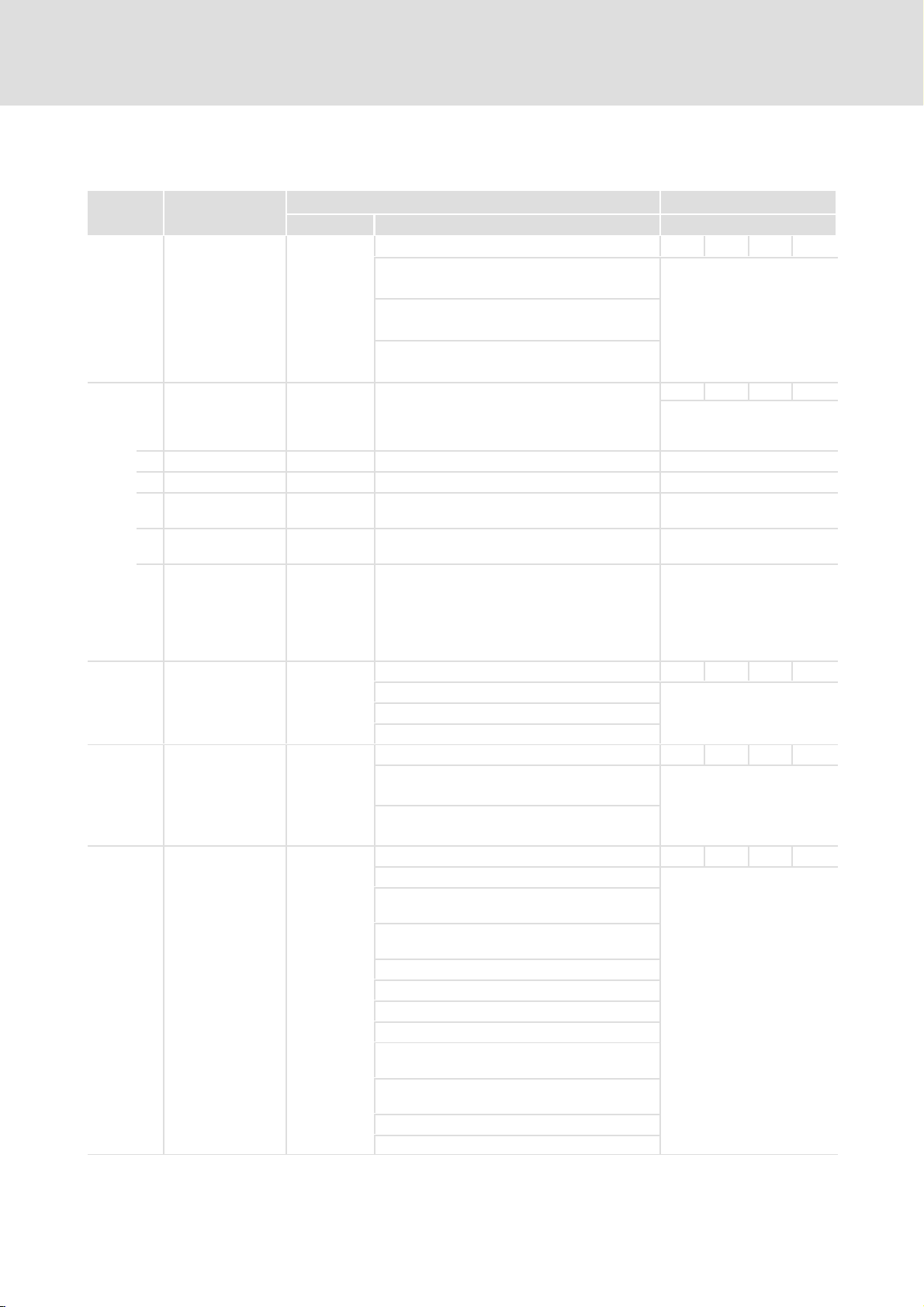
6.6.6 PNUs for parameter setting
PNU Name
1000 0 Position Set
1001 Position Data
1002 0 Start Set Number 68
1003 0 Motion Profile Type 0
1050 0 Homing Method 1
Number
0 Target Position 0 −32768 {1 inc} 32768 Target position
1 Profile Velocity 1000 0 {1 rpm} 3000 Travelling speed
3 Acceleration
Positioning
4 Deceleration
Positioning
5 All Accelerations
Positioning
Possible settings
Lenze Selection Description
10000 0 {1 rpm/s} 20000 Acceleration
10000 0 {1 rpm/s} 20000 Deceleration
10000 0 {1 rpm/s} 20000 Acceleration and deceleration
68
Characteristics
UINT16 RW
0 ... 63 Standard position data sets Position data sets of the
64 ... 67 Reserved
68 PROFIBUS position data set
0 ... 63 Standard position data sets When positioning is started
64 ... 67 Reserved
68 PROFIBUS position data set
0 Jerk−limited ramp is deactivated The acceleration/deceleration
2 Jerk−limited ramp is activated
Homing to Selection of the homing
1 the negative limit switch with zero
pulse evaluation
2 the positive limit switch with zero
pulse evaluation
17 the negative limit switch
18 the positive limit switch
33, 34 the zero pulse
35 the actual position (no movement)
−1 the negative end stop with zero pulse
evaluation
−2 the positive end stop with zero pulse
evaluation
−17 the negative end stop
−18 the positive end stop
controller. The selected data
set can be parameterised via
PNU 1001.
For position data set 68,
additional settings can be
transferred via bits 4, 12 and
13 of control word 1.
INT32 RW
Parameterisation of the
position data set selected via
PNU 1000.
l Writes the set value to
PNU 1001.3 and
PNU 1001.4.
l Reads out PNU 1001.3
only.
UINT8 RW
via control word 1, the
selected data set is activated.
UNIT16 RW
time of the ramp cannot be
adjusted. When the ramp is
activated, the maximum time
(50 ms) is set automatically.
INT8 RW
method to be used.
l 38
KHB 13.0004−EN 2.1
Page 39

Commissioning
"Positioning" mode
PNUs for parameter setting
6
NamePNU
1051 0 Home Offset 0 −32767 {1 inc} 32767
Possible settingsNamePNU
Characteristics
DescriptionSelectionLenze
INT32 RW
Definition of the distance
between the zero position
and the reference point of a
homing sequence.
l Positive values shift the
zero point to the positive
direction with respect to
the reference point.
KHB 13.0004−EN 2.1
l 39
Page 40

6
Commissioning
Actual values
Actual position
6.7 Actual values
6.7.1 Actual position
ƒ Reading the actual position.
Due to the physical units, the resulting value may be higher than the maximum value
which can be represented by PNU 1100.
PNU Name Possible settings
Lenze Selection Description
1100 0 Position Actual
Value
6.7.2 Actual speed value
ƒ Reading the actual speed value.
PNU Name Possible settings
Lenze Selection Description
1101 0 Velocity Actual
Value
{1 inc}
{1 rpm}
Characteristics
INT32 RO
Actual position value. The
value is scaled to the physical
unit set for PROFIBUS.
Characteristics
INT32 RO
Actual speed value. The value
is scaled to the physical unit
set for PROFIBUS.
6.7.3 Actual value of active current
ƒ Reading the actual value of the active current.
PNU Name Possible settings
Lenze Selection Description
1102 0 Current Actual
Value
{1 }
Characteristics
INT32 RO
Actual value of active current.
The value refers to the rated
motor current.
l 40
KHB 13.0004−EN 2.1
Page 41

Commissioning
Actual values
Digital outputs
6
6.7.4 Digital outputs
ƒ States of the digital outputs.
PNU Name Possible settings
Lenze Selection Description
1140 0 Digital Outputs 0
6.7.5 Digital inputs
ƒ Reading the states of the digital inputs.
PNU Name Possible settings
Lenze Selection Description
1141 0 Digital Inputs 0
Characteristics
UINT32 RW
Bit Value Triggering of the digital
0 00000001
1 ... 15 Reserved
16 00010000
17, 18 00060000
19 ... 32 Reserved
Bit Value Actual states of the digital
0 00000001
1 Reserved
2 00000002
3 00000008
16 ... 25 03FF0000
26 ... 32 Reserved
h
h
h
h
h
h
h
Holding brake
(read only)
Ready for
operation (read
only)
DOUT1, DOUT2
(read and write)
Negative limit
switch (DIN7)
Positive limit
switch (DIN7)
Controller enable
is missing (DIN9)
DIN0 ... DIN9
outputs.
Important! Up to 10 ms may
pass between triggering and
switching of the output.
The state of an output can be
checked by reading out the
parameter.
Characteristics
UINT32 RO
inputs.
The available digital inputs
depend on the
parameterisation of the
controller
KHB 13.0004−EN 2.1
l 41
Page 42

6
Commissioning
Actual values
Motor data
6.7.6 Motor data
ƒ Via PNU 1290.1 (iit Ratio Motor) you can read out the actual utilisation of the I
limitation in [].
PNU Name Possible settings
Lenze Selection Description
1160 Temperature Reading of different
0 Power stage
temperature
1 Motor temperature {1 °C}
1290 Motor Data Overload protection for the
0 iit Time Motor 2000 0 {1 ms} 10000
1 iit Ratio Motor {1 }
{1 °C}
Characteristics
temperatures.
INT16 RO
Reading of the current power
stage temperature.
INT16 RO
Reading of the current motor
temperature.
motor connected.
UNIT16 RW
Time for which the motor is
fed with the specified
maximum current.
l When the time has
elapsed, the motor current
is automatically limited to
the rated current set.
UNIT16 RO
Reading−out of the actual
utilisation of the I
limitation.
2
t
2
t
6.7.7 Operating modes
PNU Name
1500 0 Operating Mode
Possible settings
Lenze Selection Description
00
10
Characteristics
UINT8 RO
Speed control Reading−out of the operating
h
h
Positioning
mode.
l 42
KHB 13.0004−EN 2.1
Page 43
7 Parameter setting
7.1 Physical units
) Note!
Application−specific parameters depend on the physical units. For this reason
set the physical units before starting to parameterise the application.
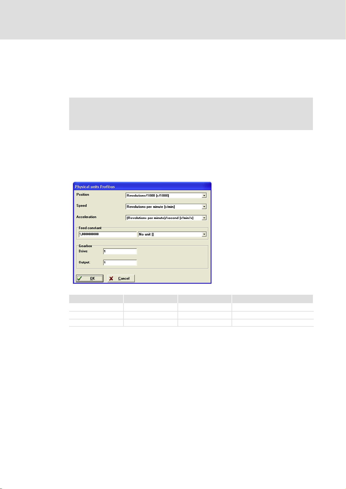
With the »Small Drives Control (SDC)« program you can parameterise the controller in such
a way that the physical quantities can be entered/read out on the drive directly in the
desired units (e.g. position values of a linear axis in millimetres and speeds in millimetres
per second).
ƒ Open the Parameters W Fieldbus W Profibus... W Display units... menu.
Parameter setting
Physical units
7
931E_026
Quantity Designation Unit Explanation
Length position_units Increments 65535 increments per revolution
Speed speed_units rpm Revolutions per minute
Acceleration acceleration_units rpm/s Speed increase per second
KHB 13.0004−EN 2.1
l 43
Page 44
7
Parameter setting
Physical units
U
E
x
1
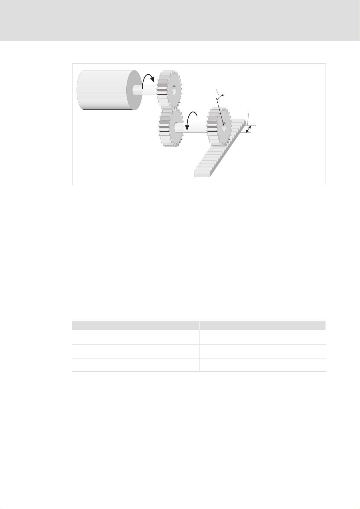
Fig. 8 Gearbox factors
U
Input−end speed
E
Output−end speed
U
A
Position_units in degrees
x
1
Position_units in mm
x
2
U
A
x
2
931e_415
Notes on settings
ƒ From the set physical units conversion factors are automatically generated
internally. The conversion factors consist of a numerator and a denominator and
may not be longer than 32 bits.
ƒ The value of the feed constant is ignored for the respective physical unit if the feed
constant has a translatory unit and a rotatory unit is selected for the physical
quantity.
ƒ If the entries for the factors or physical units are incorrect, an overflow occurs and
the value is rejected.
ƒ Examples for incorrect settings:
Incorrect setting Effect
Position in [revolutions] and
feed constant in [mm/revolution]
Position in [mm] and
feed constant without a unit
Position in [mm] and
feed constant in [mm/revolution]
ƒ The error message 59 ("General arithmetic error") is generated
The feed constant is ignored.
The feed constant is considered as a gearbox factor.
The feed constant is evaluated using the factor 1000.
– if incorrect settings result in values which cannot be represented after internal
conversion,
– if transition states occur which cause the overflow of physical units.
Remedy:
– Check the settings of the physical units and correct them if necessary.
– Save the settings and carry out a reset. If the error message 59 is not generated
anymore, the physical units are valid.
l 44
KHB 13.0004−EN 2.1
Page 45

Parameter setting
Global parameters
Saving of parameter set
7
7.2 Global parameters
7.2.1 Saving of parameter set
ƒ Saving parameters on the controller.
PNU Name Possible settings
Lenze Selection Description
971 0 Transfer into a
non−volatile
memory
0
0 No action Save current parameter set
1 Save
2 ... 65535Reserved
Characteristics
UNIT16 RW
and all position data sets
Also saves position data set
68.
7.2.2 Setting of manual jog (inching mode)
ƒ Simplified access to the values for inching speed and acceleration.
PNU Name Possible settings
Lenze Selection Description
1040 Jog Value Simplified access to the
0 Jog Velocity 100 0 {1 rpm} 6000
1 Symmetrical Jog
Accelerations
10000 0 {1 rpm/s} 20000
Characteristics
inching values.
This type of access reduces
the amount of data to be
transferred in the cyclic data
telegram. Internally all
parameters are written.
INT32 RW
Inching speed
l The physical unit is the
PROFIBUS speed
UINT32 RW
Inching acceleration
l The physical unit is the
PROFIBUS acceleration
l The value read is the
acceleration
KHB 13.0004−EN 2.1
l 45
Page 46

7
Parameter setting
Global parameters
Motor data
7.2.3 Motor data
ƒ Via PNU 1290.0 (iit Time Motor) you can set the duration of the maximum motor
current.
When the time has elapsed, the motor current is automatically limited to the
parameterised rated motor current.
ƒ Via PNU 1290.1 (iit Ratio Motor) you can read out the actual utilisation of the I
limitation in [].
PNU Name Possible settings
Lenze Selection Description
1160 Temperature Reading of different
0 Power stage
temperature
1 Motor temperature {1 °C}
1290 Motor Data Overload protection for the
0 iit Time Motor 2000 0 {1 ms} 10000
{1 °C}
1 iit Ratio Motor {1 }
Characteristics
temperatures.
INT16 RO
Reading of the current power
stage temperature.
INT16 RO
Reading of the current motor
temperature.
motor connected.
UNIT16 RW
Time for which the motor is
fed with the specified
maximum current.
l When the time has
elapsed, the motor current
is automatically limited to
the rated current set.
UNIT16 RO
Reading−out of the actual
utilisation of the I
limitation.
2
t
2
t
l 46
KHB 13.0004−EN 2.1
Page 47

Parameter setting
"Speed control" mode
Speed setpoint
7
7.3 "Speed control" mode
7.3.1 Speed setpoint
ƒ Setting the speed setpoint.
In the "speed control" mode the "speed setpoint" selector is selected automatically.
PNU Name Possible settings
Lenze Selection Description
1010 0 Target Velocity 0 0 {1 rpm} 6000
Characteristics
INT32 RW
Selection of the speed
setpoint.
l If the speed control mode
is selected in SDC, the
selector under "setpoint
selection" changes over if
required: AIN0/1, Profibus
or RS232
KHB 13.0004−EN 2.1
l 47
Page 48

7
Parameter setting
"Speed control" mode
Acceleration value
7.3.2 Acceleration value
ƒ Parameterising the acceleration values for the speed control mode.
PNU 1011.0 and PNU 1011.1 both enable access to the acceleration for CW and CCW
direction of rotation. If a value is transferred, it is valid for both directions of rotation.
PNU 1011.2 enables access to the acceleration and deceleration ramp for both directions
of rotation. If a value is transferred, it is valid for accelerating and decelerating in both
directions of rotation.
The data is interpreted according to the selected physical units. (¶ 43)
Please observe that only the actual value of the acceleration ramp for the positive direction
of rotation is read.
PNU Name Possible settings
Lenze Selection Description
1011 Acceleration for
Velocity Control
0 Acceleration
Velocity Control
1 Deceleration
Velocity Control
2 All Accelerations
Velocity Control
Characteristics
UINT32 RW
Setting the acceleration and
deceleration for the speed
control mode
10000 0 {1 rpm/s} 20000 Acceleration, the value set is
valid for both directions of
rotation
l Reads out only the actual
value for the positive
direction of rotation
10000 0 {1 rpm/s} 20000 Deceleration, the value set is
valid for both directions of
rotation
l Reads out only the actual
value for the positive
direction of rotation
10000 0 {1 rpm/s} 20000 Acceleration and
deceleration, the value set is
valid for both directions of
rotation
l Writes the value set to
PNU 1011, subindexes 0
and 1
l Reads out the actual value
for the positive direction
of rotation under
PNU 1011, subindex 0
l 48
KHB 13.0004−EN 2.1
Page 49

Parameter setting
"Positioning" mode
Selection of position data set for parameter setting
7
7.4 "Positioning" mode
7.4.1 Selection of position data set for parameter setting
ƒ Selecting the position data set of the controller to be parameterised via PNU 1001.
The position data set for PROFIBUS can be parameterised via the "SDC" program and saved
in the controller. In this way the parameters of an application which do not have to be
changed during operation can be specified permanently. You just have to enter, for
instance, the values for accelerations once. These values then do not have to be transferred.
PNU Name Possible settings
Lenze Selection Description
1000 0 Position Set
Number
68
0 ... 63 Standard position data sets Position data sets of the
64 ... 67 Reserved
68 PROFIBUS position data set
7.4.2 Setting of positioning profile parameters
Characteristics
UINT16 RW
controller. The selected data
set can be parameterised via
PNU 1001.
For position data set 68,
additional settings can be
transferred via bits 4, 12 and
13 of control word 1.
ƒ Changing the parameters of the position data set selected via PNU 1000.
The data is interpreted according to the selected physical units. (¶ 43)
PNU Name Possible settings
Lenze Selection Description
1001 Position Data
0 Target Position 0 −32768 {1 inc} 32768 Target position
1 Profile Velocity 1000 0 {1 rpm} 3000 Travelling speed
3 Acceleration
Positioning
4 Deceleration
Positioning
5 All Accelerations
Positioning
10000 0 {1 rpm/s} 20000 Acceleration
10000 0 {1 rpm/s} 20000 Deceleration
10000 0 {1 rpm/s} 20000 Acceleration and deceleration
Characteristics
INT32 RW
Parameterisation of the
position data set selected via
PNU 1000.
l Writes the set value to
PNU 1001.3 and
PNU 1001.4.
l Reads out PNU 1001.3
only.
KHB 13.0004−EN 2.1
l 49
Page 50
7
Parameter setting
"Positioning" mode
Position data set at starting of positioning
7.4.3 Position data set at starting of positioning
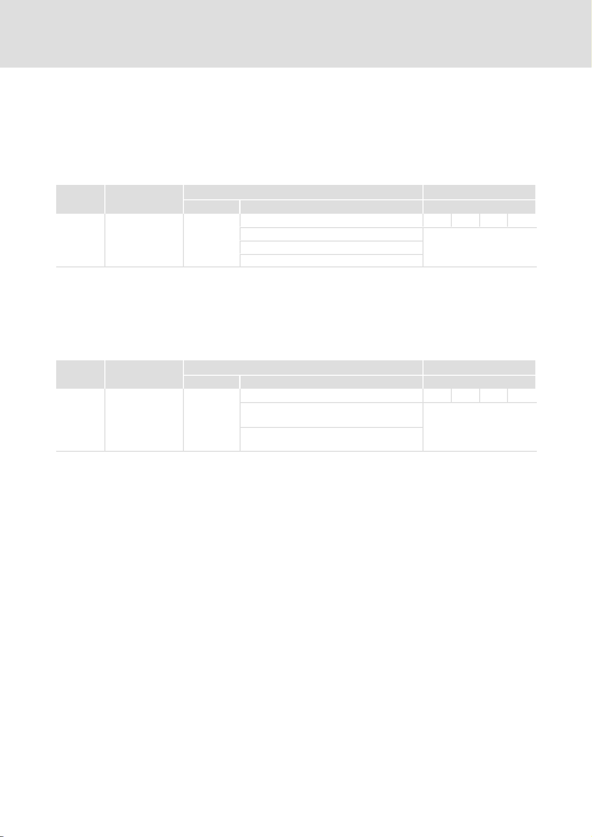
ƒ Selection of the position data set to be started via the control word 1 when a
command to start a positioning process is issued.
The controller is provided with 64 storable standard position data sets which can be
selected via 8 bits.
PNU Name Possible settings
Lenze Selection Description
1002 0 Start Set Number 68
0 ... 63 Standard position data sets When positioning is started
64 ... 67 Reserved
68 PROFIBUS position data set
7.4.4 Jerk limitation
ƒ Activation of the jerk−limited ramp.
With the activation the maximum time (50 ms) is automatically set for the ramp. Only the
activation can be controlled via Profibus.
PNU Name Possible settings
Lenze Selection Description
1003 0 Motion Profile Type 0
0 Jerk−limited ramp is deactivated The acceleration/deceleration
2 Jerk−limited ramp is activated
Characteristics
UINT8 RW
via control word 1, the
selected data set is activated.
Characteristics
UNIT16 RW
time of the ramp cannot be
adjusted. When the ramp is
activated, the maximum time
(50 ms) is set automatically.
l 50
KHB 13.0004−EN 2.1
Page 51
Parameter setting
"Positioning" mode
Homing modes
7
7.4.5 Homing modes
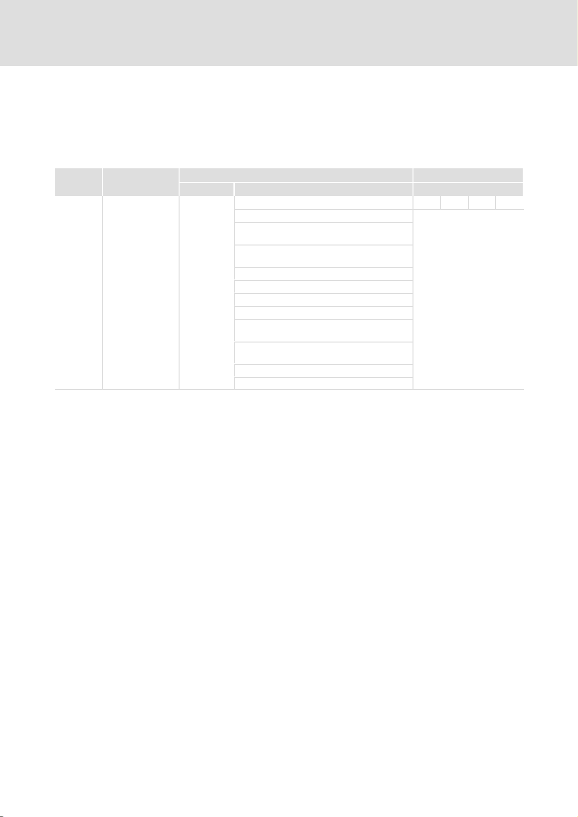
ƒ Selection of the homing method.
A detailed description of the different methods is given in the software manual for the
controller.
PNU Name Possible settings
Lenze Selection Description
1050 0 Homing Method 1
Homing to Selection of the homing
1 the negative limit switch with zero
pulse evaluation
2 the positive limit switch with zero
pulse evaluation
17 the negative limit switch
18 the positive limit switch
33, 34 the zero pulse
35 the actual position (no movement)
−1 the negative end stop with zero pulse
evaluation
−2 the positive end stop with zero pulse
evaluation
−17 the negative end stop
−18 the positive end stop
Characteristics
INT8 RW
method to be used.
KHB 13.0004−EN 2.1
l 51
Page 52
7
Parameter setting
"Positioning" mode
Homing offset
7.4.6 Homing offset
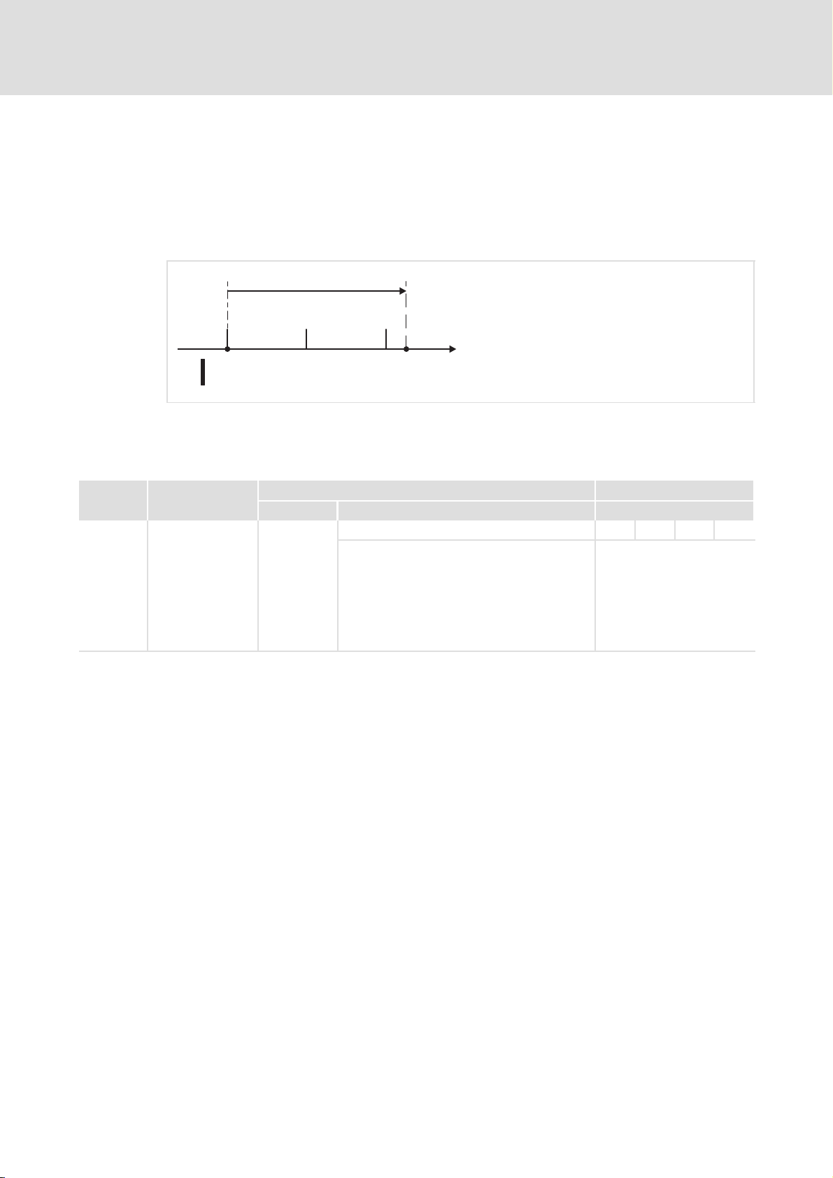
ƒ Defining the distance between the home position (zero position) and the reference
point of a homing run.
Positive values shift the zero point to the positive direction with respect to the reference
point.
01
Home Offset
x
2
Fig. 9 Interpretation of the home offset
0 Reference point, first zero pulse
1 Zero position
2 Limit switch
PNU Name
1051 0 Home Offset 0 −32767 {1 inc} 32767
Possible settings
Lenze Selection Description
931_029
Characteristics
INT32 RW
Definition of the distance
between the zero position
and the reference point of a
homing sequence.
l Positive values shift the
zero point to the positive
direction with respect to
the reference point.
l 52
KHB 13.0004−EN 2.1
Page 53
Parameter setting
Error management
Setting of responses
7
7.5 Error management
7.5.1 Setting of responses
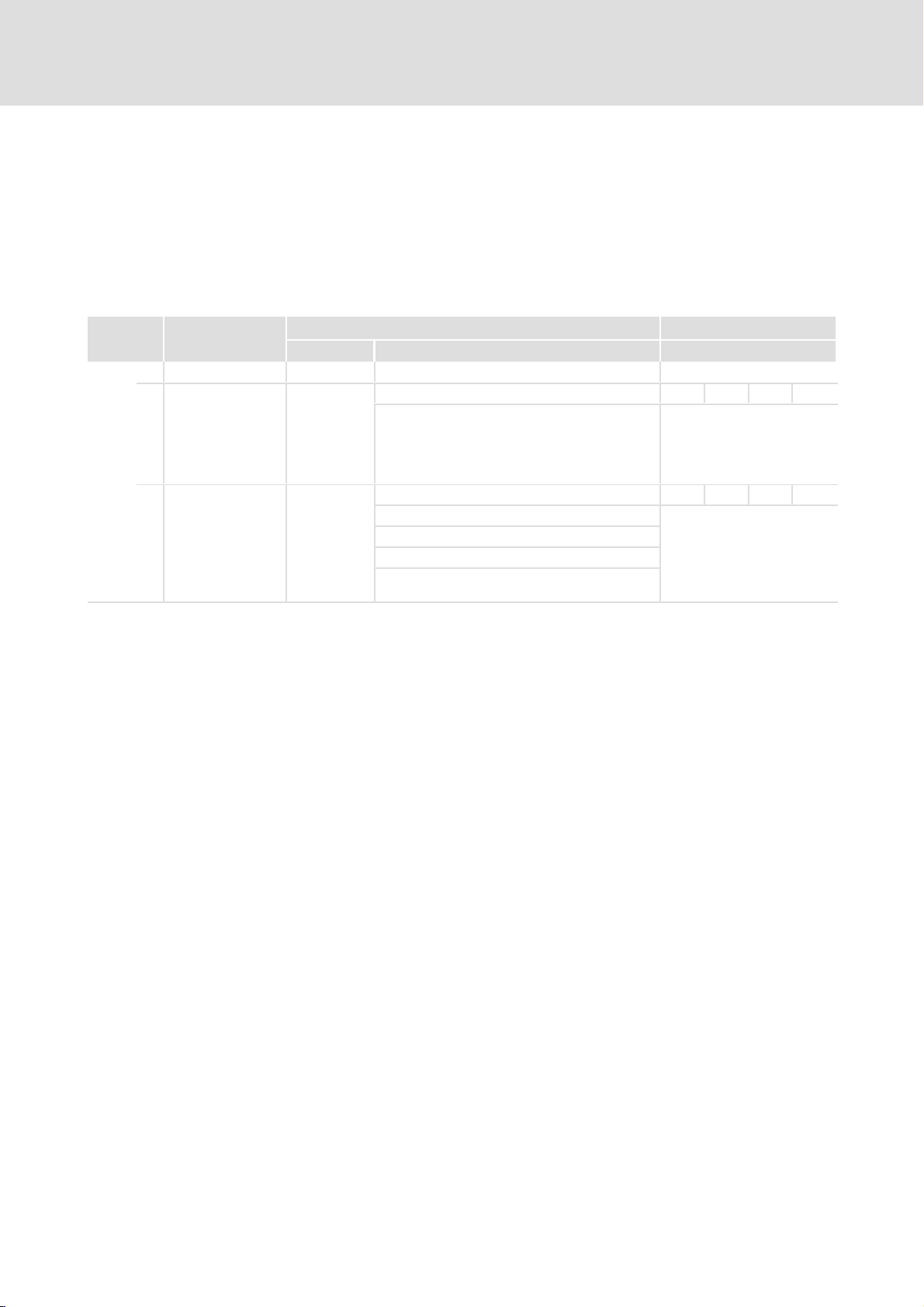
ƒ Selection of the error number for which a response is to be set.
A description of the error messages and the possible responses is given in the chapter
"Table of error messages". (¶ 62)
PNU Name Possible settings
Lenze Selection Description
1610 Error Management Error management
0 Error Number
1 Error Reaction Code
1
00
03
05
08
h
No response Response of the controller to
h
Warning
h
Emergency stop
h
Power stage off (motor coasts to
h
standstill)
{1} 40hSelection of the error number
Characteristics
UNIT8 RW
for which a response is to be
set under PNU 1610.1.
Overview of error numbers:
^ 62
UNIT8 RW
an error event.
Notes on settings: ^ 62
KHB 13.0004−EN 2.1
l 53
Page 54

8
Device control
Important notes
8 Device control
8.1 Important notes
} Danger!
Uncontrolled motor movements can occur
If the power stage of the controller is inhibited, the motor coasts to stop
without braking.
Possible consequences:
ƒ Injury to persons through uncontrolled machine movements.
Protective measures:
ƒ Install a mechanical motor brake which is activated automatically when the
power stage is inhibited.
The controller is controlled via PROFIdrive by means of a data word (LOW byte and HIGH
byte):
ƒ The master uses the control word 1 to control the essential function of the
controller.
– The assignment of the control word 1 corresponds to the PROFIdrive profile. Some
functions have manufacturer−specific definitions.
– The controller first accepts the parameter data and then evaluates the control
word 1. This ensures that the sequence of the positioning steps is correct.
– State changes triggered via the control word 1 first have to be confirmed via the
status word 1 before another command can be sent via the control word 1.
ƒ The controller (slave) uses the status word 1 to signal its state to the master.
– The assignment of the status word 1 corresponds to the PROFIdrive profile. Some
functions have manufacturer−specific definitions.
– The status word 1 displays the different states of the controller.
54
l
KHB 13.0004−EN 2.1
Page 55
8.2 "Speed control" mode
8.2.1 Control word 1
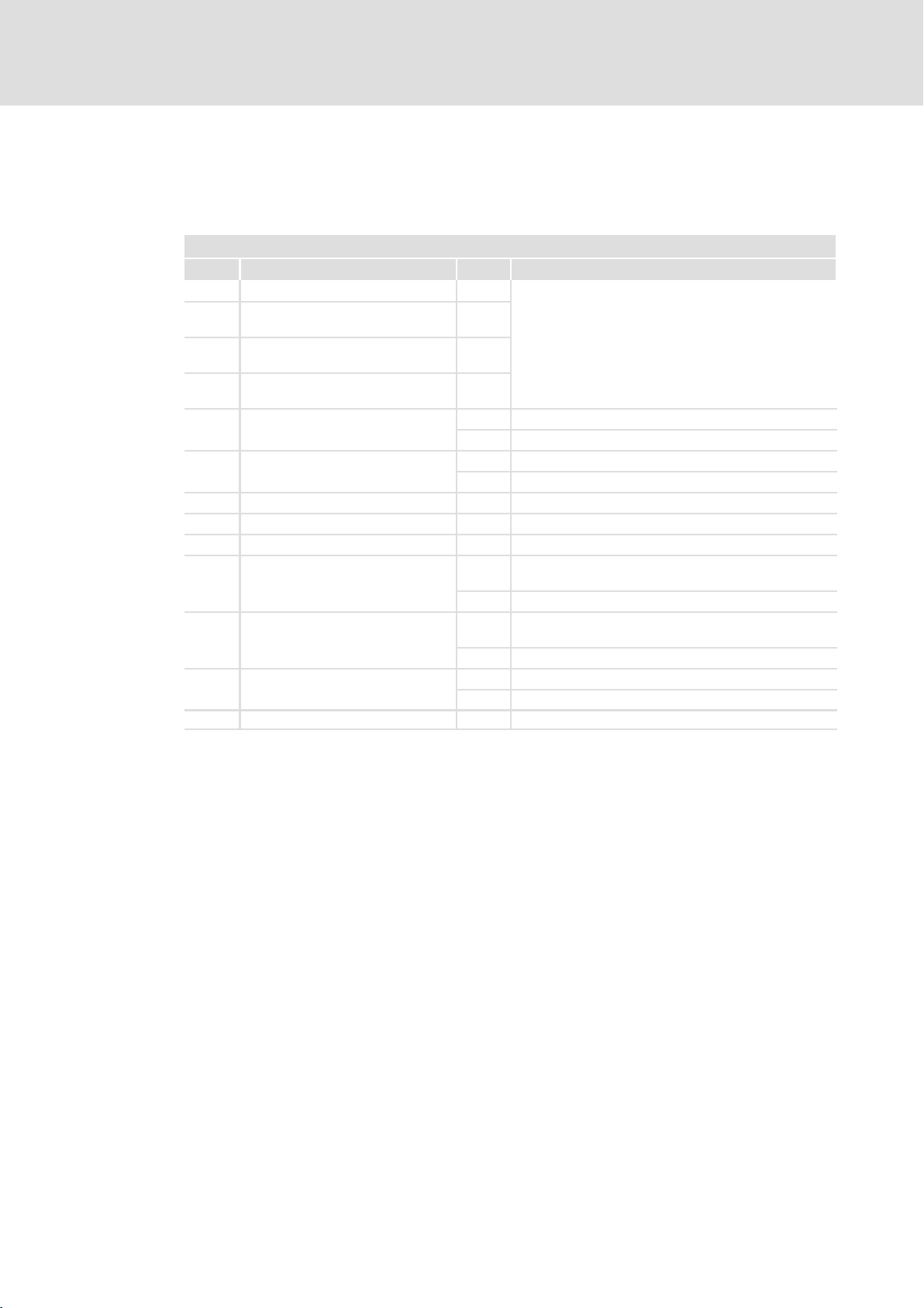
Control word 1 in "speed control" mode
Bit Command Value Meaning
0 ON / OFF (OFF 1)
1 No coast stop (no OFF 2)
Coast stop (OFF 2)
2 No quick stop (no OFF 3)
Quick stop (OFF 3)
3 Enable operation
Disable operation
4 Enable ramp generator
5 Stop ramp generator
6 Enable setpoint 0 Deactivate all ramp setpoint inputs.
7 Acknowledge error 0 ® 1 Acknowledge the error.
8 Inching mode 1 on/off
9 Inching mode 2 on/off
10 Control authority
11 15 Device−specific No function.
0 ® 1: LOW−HIGH edge
1 ® 0: HIGH−LOW edge
Device control
"Speed control" mode
Control word 1
See chapter "State diagram" ^ 59
0 Inhibit all speed setpoints.
1 Enable all speed setpoints.
0 Stop setpoint ramp.
1 Activate setpoint ramp.
1 Enable all ramp setpoint inputs.
0 ® 1 Inching mode with travelling speed and positive speed
setpoint.
1 ® 0 Stop inching mode with delay.
0 ® 1 Inching mode with travelling speed and negative speed
setpoint.
1 ® 0 Stop inching mode with delay.
0 The control authority of the master is deactivated.
1 The master requests the control authority.
8
KHB 13.0004−EN 2.1
l
55
Page 56
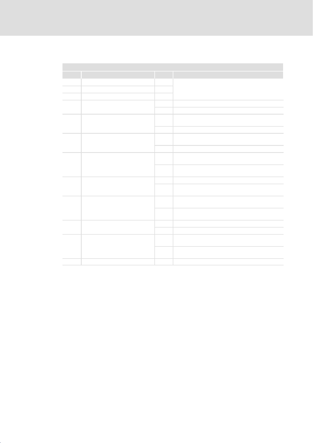
8
Device control
"Speed control" mode
Status word 1
8.2.2 Status word 1
Status word 1 in "speed control" mode
Bit State Value Meaning
0 READY_FOR_SWITCH_ON
1 READY_TO_OPERATE
2 OPERATION
3 Fault present
4 No coast stop (no OFF 2)
5 No quick stop (no OFF 3)
6 Switching on inhibited
7 Warning present
8 Speed error
9 Control authority
10 Actual speed
11 15 Device−specific No function.
Coast stop (OFF 2)
Quick stop (OFF 3)
Switching on not inhibited
No warning present
See chapter "State diagram" ^ 59
0 Error pending.
1 No error.
0 Command "OFF 2" of control word 1.
(Power stage is off)
1 Command "no OFF 2" of control word 1.
0 Command "OFF 3" of control word 1.
(Quick stop is active)
1 Command "no OFF 3" of control word 1.
0 The self−test of the controller has not been completed.
Communication with the master is not possible.
1 The self−test of the controller is completed.
Communication with the master is possible.
0 No warning.
1 Warning is active or setpoint is inhibited by limit
switch in at least one direction of rotation.
0 The actual speed is not within the parameterisable
signalling window around the setpoint speed.
1 The actual speed is within the parameterisable
signalling window around the setpoint speed.
0 The master has no control authority.
1 The master has the control authority.
0 Actual speed < freely configurable reference speed. The
sign is taken into account.
1 Actual speed > freely configurable reference speed. The
sign is taken into account.
56
l
KHB 13.0004−EN 2.1
Page 57
8.3 "Positioning" mode
8.3.1 Control word 1
Control word 1 in "positioning" mode
Bit Command Value Meaning
0 ON / OFF (OFF 1)
1 No coast stop (no OFF 2)
Coast stop (OFF 2)
2 No quick stop (no OFF 3)
Quick stop (OFF 3)
3 Enable operation
Disable operation
4 Cancel travel task
5 Intermediate stop
6 Activate travel task
(manufacturer−specific)
7 Acknowledge error 0 ® 1 Acknowledge the error.
8 Inching mode 1 on/off
9 Inching mode 2 on/off
10 Control authority
11 Start/stop homing
12 Positioning
(manufacturer−specific)
13 Start during a running positioning
(manufacturer−specific)
14, 15 Device−specific No function.
0 ® 1: LOW−HIGH edge
1 ® 0: HIGH−LOW edge
Device control
"Positioning" mode
Control word 1
See chapter "State diagram" ^ 59
0 Cancel positioning/do not start
positioning.
1 Do not cancel positioning.
0 Do not start positioning.
1 No intermediate stop.
0 ® 1 Accelerate drive to travelling speed.
1 ® 0 Stop drive with delay.
0 ® 1 Start the position data set which is set under
PNU 1002/0. For PNU 1002/0 = 68 the settings of bits
4, 12 and 13 are transferred.
0 ® 1 Start inching mode in positive direction.
1 ® 0 Stop inching mode with delay.
0 ® 1 Start inching mode in negative direction.
1 ® 0 Stop inching mode with delay.
0 The control authority of the master is deactivated.
1 The master requests the control authority.
0 No homing.
1 Continue homing.
0 ® 1 Start homing.
1 ® 0 If homing is active, it is cancelled without error.
If homing is completed, the command does not cause
any action.
0 Absolute positioning.
1 Relative positioning.
0 Start next positioning after
completion of the active
positioning.
1 Cancel active positioning and start
next positioning.
Settings only
take effect for
position data set
68.
Settings only
take effect for
position data set
68.
8
KHB 13.0004−EN 2.1
l
57
Page 58
8
Device control
"Positioning" mode
Status word 1
8.3.2 Status word 1
Status word 1 in "positioning" mode
Bit State Value Meaning
0 READY_FOR_SWITCH_ON
1 READY_TO_OPERATE
2 OPERATION
3 Fault present
4 No coast stop (no OFF 2)
5 No quick stop (no OFF 3)
6 Switching on inhibited
7 Warning present
8 Following error
9 Control authority
10 Target position
11 Home position
12 Traversing task acknowledge
13 Actual speed
14, 15 Device−specific No function.
Coast stop (OFF 2)
Quick stop (OFF 3)
Switching on not inhibited
No warning present
See chapter "State diagram" ^ 59
0 Error pending.
1 No error.
0 Command "OFF 2" of control word 1.
(Power stage is off)
1 Command "no OFF 2" of control word 1.
0 Command "OFF 3" of control word 1.
(Quick stop is active)
1 Command "no OFF 3" of control word 1.
0 The self−test of the controller has not been completed.
Communication with the master is not possible.
1 The self−test of the controller is completed.
Communication with the master is possible.
0 No warning
1 Warning is active or setpoint is inhibited by limit
switch in at least one direction of rotation.
0 Following error.
1 No following error.
0 The master has no control authority.
1 The master has the control authority.
0 The running positioning is active or the actual position
is not within the target window.
1 The running positioning has been completed and the
actual position is within the target window.
0 Homing has not been carried out or the position
information has become invalid due to an error.
1 Homing has been completed successfully.
0 The travel task has been accepted.
1 The controller is accepting a new travel task.
0 The actual speed is out of the signalling window
referred to the reference speed (see Messages dialog
box in SDC and the description in the software manual
for the controller).
1 The actual speed is within the signalling window
referred to the reference speed (see Messages dialog
box in SDC and the description in the software manual
for the controller).
58
l
KHB 13.0004−EN 2.1
Page 59
8.4 State diagram
S1: SWITCHING_ON_INHIBITED
Power on
Device control
State diagram
Status word 1
8
(1)
S2: READY_FOR_SWITCH_ON
(2)
(8)
S3: SWITCHED_ON
(7) (9)(3)
S4:OPERATION
Fig. 10 Simplified state diagram
(6) (12)
(5)
(10)
(11)(4)
931e_027
Controller states
Status word 1
State Bit 6 Bit 2 Bit 1 Bit 0 Description
0040h0004h0002h0001
Power on Switch−on and initialisation of the controller.
SWITCHING_ON_INHIBITED 1 0 0 0 The initialisation is completed.
READY_FOR_SWITCH_ON 0 0 0 1 Waiting for the controller to be enabled.
SWITCHED_ON 0 0 1 1 The controller is enabled (DIN9 = HIGH).
OPERATION 0 1 1 1 The controller is operating. The drive is controlled
h
Communication via PROFIBUS is not yet possible.
The power stage is deactivated, the motor
produces zero torque.
Communication via PROFIBUS is possible.
The controller changes to this state when an error
message occurs.
The controller can be enabled via DIN9 = HIGH or
via the controller enable logic "DIN9 and
PROFIBUS".
according to the selected operating mode.
KHB 13.0004−EN 2.1
l
59
Page 60
8
Device control
State diagram
Status word 1
Commands and state transitions of the controller
Control word 1
Command Bit 3 Bit 2 Bit 1 Bit 0 State
0008h0004h0002h0001
OFF × 1 1 0 1, 5, 11 The controller is inhibited
ON × 1 1 1 2 The controller is enabled
Coast stop × × 0 × 6, 7, 8 The power stage is deactivated. The
Quick stop × 0 1 × 9, 10, 12 The controller is inhibited
Disable operation 0 1 1 1 4 The controller is inhibited
Enable operation 1 1 1 1 3 The controller is enabled
× Bit state is not relevant
transitions
h
Description
(DIN9 = LOW). The motor is braked
to standstill in a controlled manner.
(DIN9 = HIGH).
drive coasts.
(DIN9 = LOW). The motor is braked
to standstill in a controlled manner.
(DIN9 = LOW). The motor is braked
to standstill in a controlled manner.
(DIN9 = HIGH), the power stage is
activated. The drive is controlled
according to the selected operating
mode.
60
l
KHB 13.0004−EN 2.1
Page 61
Troubleshooting and fault elimination
9 Troubleshooting and fault elimination
9.1 Fault elimination
Fault Remedy
The controller operates faultlessly but the
PLC does not receive any process data.
The controller is in the wrong operating
mode / does not receive any control
commands.
The master signals an error during data
transmission (e.g. access error).
The power stage is active but the motor
does not rotate.
No processing of the PROFIdrive profile, but
the motor is rotating.
Correct the message assignment in SDC:
l Assign the response message 0 to the receive message 0 and
the response message 1 to the receive message 1.
Check the telegram identifier in byte 0:
l "Positioning" mode: Byte 0 = E0
message 0).
l "Speed control" mode: Byte 0 = E1
message 1/response message 1).
Check the memory area used by the PLC in the hardware
configuration.
Enter the torque setpoint limitation in the receive message:
l For limitation via analog input (PNU 1022.0 = 1, 2), apply a
voltage at input (AIN).
l For limitation via PROFIBUS (PNU 1022.0 = 7), enter the setpoint
directly via PNU 1022.1.
Check that the controller enable logic is entered in the receive
message and that the value is set appropriately.
Fault elimination
(receive message 0/response
h
(receive
h
9
9.2 Error messages
9.3 Transfer of error messages
The error messages of the controller are coded in the error numbers 1 ... 64. These error
numbers can be read via PNU 1601:
ƒ PNU 1601.0 transfers the error numbers 1 ... 32
ƒ PNU 1601.1 transfers the error numbers 33 ... 64
PNU Name
1601
Error Code Error messages
0 Error Field 0
1 Error Field 1
Possible settings
Lenze Selection Description
Characteristics
UINT32 RO
Error numbers 1 ... 32 of the
controller
UINT32 RO
Error numbers 33 ... 64 of the
controller
KHB 13.0004−EN 2.1
l
61
Page 62

62
l
9.4 Table of error messages
How to read the table
Response Symbol Meaning
Type
Setting
A
H Emergency stop The motor is decelerated to zero speed at its current limit. An installed holding brake is applied. The power stage
W Warning The power stage remains switched on. The controller continues operating. The generated warning message can
O Off No response. The warning message is suppressed.
þ Lenze setting
¨ Setting is possible
− Setting is not possible
Switch−off of power stage The motor coasts to standstill.
is switched off.
be read via the fieldbus or the RS232 interface.
9
Troubleshooting and fault elimination
Table of error messages
KHB 13.0004−EN 2.1
Page 63
KHB 13.0004−EN 2.1
Error
number
03 Motor overtemperature < 100 ms þ þ þ ¨ Motor overtemperature l Check if the motor cooling via the motor housing is
04 Overtemperature/
l
05 SinCos supply error < 5 ms þ − − −
06 SinCos−RS485 communication
07 SinCos track signal error < 5 ms þ − − −
08 Resolver, track signal error or
09 5V−electronic supply error < 5 ms þ − − −
10 12V−electronic supply error < 5 ms þ − − −
63
Meaning Activation
time
< 100 ms þ þ − − Overtemperature/undertemperature of
undertemperature of the
power electronics
< 5 ms þ − − −
error
< 5 ms þ − − −
carrier failure
Response
A H W O
Cause Remedy
impeded as a result of deposits, etc. (if necessary, clean the
motor).
l Are there any other sources of heat near the motor that
may additionally increase the ambient temperature and
thus lead to a reduced heat loss dissipation?
l Check the controller settings, poor settings will lead to an
unnecessary heat generation.
l Reduce the load torque of the motor.
l Check the setting of the temperature sensor.
l Check the resolver and encoder cable for an open circuit.
l Check the resolver position adjustment.
controller
Resolver or SinCos encoder error, reliable
detection only possible after approx. ½
motor revolution
Angle encoder/ Hall−effect sensor
defective.
Collapse of supply voltage due to a wiring
error on X2
l Error on techno module X8.
l Voltage supply failure.
Angle encoder or SinCos encoder defective. Replace encoder.
Collapse of supply voltage due to a wiring
error on X2
Voltage supply failure. Electronic error on the controller. Send the controller in for
l Check if the controller has been correctly mounted into the
control cabinet:
– Heatsink must have large−surface contact with the
housing of the control cabinet.
– If required, remove other sources of heat from the
vicinity of the controller.
l Clean the ventilation slots of the controller.
l Optimise the controller settings (poor settings will lead to
an unnecessary heat generation).
l Carry out a resolver position adjustment.
l Reduce the load torque of the motor.
l Check resolver plug connection.
l Check resolver cable for open or short circuit.
l Check pin assignment of resolver cable plug.
l Correct encoder parameters.
Replace encoder.
Check the wiring.
Send the controller in for repair.
Check the wiring.
repair.
Troubleshooting and fault elimination
Table of error messages
9
Page 64

64
number
number
11 Error in 24V supply for logic < 5 ms þ − − −
13 Offset current measurement
14 DC bus / power stage
l
15 DC−bus undervoltage < 1 ms þ þ þ ¨ DC−bus voltage too low. l Check DC bus voltage, adapt undervoltage tripping
16 DC bus overvoltage < 1 ms þ − − − DC−bus voltage > 70 V. l Check correct functioning of power supply unit and
19 I2t error of motor (I2t at 100%) < 100 ms þ þ þ ¨ I2t error of motor.
20 I2t error of controller (I2t at
26 I2t at 80% < 100 ms þ þ þ ¨ I2t error.
27 Motor temperature 5 °C
KHB 13.0004−EN 2.1
28 Power stage temperature 5 °C
MeaningError
MeaningError
error
overcurrent
100%)
below maximum value
below maximum value
RemedyCauseResponseActivation
Activation
time
time
< 5 ms þ − − − Send the controller in for repair.
< 10 ms þ − − −
< 100 ms þ þ þ ¨ I2t error of controller.
< 100 ms þ þ þ ¨ Motor is overloaded. Check drive dimensioning.
< 100 ms þ þ þ ¨ Controller is overloaded. l Check drive dimensioning.
OWHA
l 24V supply for logic too high or too low.
l Load capacity of 24V supply for logic is
too low, e.g. when activating the
holding brake.
Holding brake defective. Replace holding brake.
Overload of brake output due to incorrect
dimensioning of the brake.
Collapse of supply voltage due to a wiring
error on X3
Short circuit in the motor winding, short
circuit between motor winding and
housing.
Short circuit in the motor cable, between
two phase or between phase and shield.
Controller defective (power stage
defective, insulation fault).
RemedyCause
Send the controller in for repair.
Replace with appropriate holding brake.
Check the wiring.
Replace motor.
Replace motor cable.
Send the controller in for repair.
threshold, if necessary.
whether the supply voltage for the power stage is within
the permissible range (19.2 V DC ... 57.6 V DC).
l Set a flatter gradient for the deceleration ramp.
l Connect an external brake resistor to X2.
l Check whether other devices connected to the power
stage cause the overvoltage.
l Adapt i
l Carry out a resolver position adjustment.
l Check the selected motor data.
l Optimise the controller setting.
l Adapt the travel profile (e.g. adapt the acceleration ramps).
l Reduce the load torque of the motor.
l Check ambient temperature in the control cabinet and
2
t time of motor.
heat dissipation of the heatsink.
9
Troubleshooting and fault elimination
Table of error messages
Page 65

KHB 13.0004−EN 2.1
number
number
29 Following error monitoring < 5 ms þ þ þ ¨ Motor is blocked. l Optimise controller setting to improve the smooth
31 Limit switch error < 1 ms þ þ þ ¨
35 Time−out at quick stop < 5 ms þ ¨ ¨ ¨
36 Homing error < 5 ms þ þ þ ¨
l
65
40 Error: Motor and angle
43 Course program: Unknown
44 Course program: Invalid jump
55 PROFIBUS communication
56 RS232 communication error < 5 ms þ þ þ ¨ Communication is interfered. Ensure EMC−compliant wiring.
57 Position data set error < 5 ms þ ¨ ¨ ¨ Conflict between acceleration and selected
58 Faulty operating mode < 5 ms þ þ þ ¨ Selection of wrong operating mode. Switch to the correct operating mode while the power stage
60 Error in preliminary
62 Stack overflow < 5 ms þ ¨ ¨ ¨
63 Checksum error < 5 ms þ ¨ ¨ ¨
64 Initialisation error < 5 ms þ ¨ ¨ ¨
MeaningError
MeaningError
encoder identification
command
target
error
positioning calculation
RemedyCauseResponseActivation
Activation
time
time
< 5 ms þ ¨ ¨ ¨ Homing run completed with errors. l Check resolver plug connection.
< 5 ms þ þ ¨ ¨ Contact Lenze.
< 5 ms þ þ ¨ ¨ l The digital inputs for START1 and
< 5 ms þ þ þ ¨
< 5 ms þ ¨ ¨ ¨
OWHA
Incorrect configuration of limit switch. Check limit switch configuration.
Incorrect wiring of limit switch. Ensure correct wiring of limit switch.
Limit switch defective. Replace limit switch.
Angle encoder error occurred. Check encoder.
Motor identification failed. Repeat motor identification.
Acceleration too high. Check settings.
Homing run completed with errors. Check homing configuration.
Incorrect parameter setting for controller
and angle encoder.
Incorrect parameter setting for controller
and angle encoder.
START2 are set at the same time.
l The jump target or the target position
is invalid.
l Communication is interfered l Check installation with regard to EMC requirements.
l Double nodes in network l Check node number setting
travelling speed.
Internal error. Contact Lenze.
RemedyCause
running characteristics.
l Adapt travel profile (e.g. reduce acceleration and
deceleration ramps).
l Increase following error margin/response delay.
Check settings of controller and angle encoder.
l Check resolver cable for open or short circuit.
l Check pin assignment of resolver cable plug.
Check settings of controller and angle encoder.
Correct the settings.
Contact Lenze.
is switched on.
Troubleshooting and fault elimination
Table of error messages
9
Page 66

10
Appendix
Table of parameter numbers (PNU)
10 Appendix
10.1 Table of parameter numbers (PNU)
ƒ The PNUs are numerically sorted in ascending order to form a "reference book".
ƒ How to read the table:
Column Abbreviation Meaning
PNU
Name Name of the PNU
Possible settings
Lenze Lenze setting (value at delivery or after restoring the delivery state)
Selection 1 {%} 99 Minimum value {unit} maximum value
Characteristics
Object type
Data type
Access
Description Short, important explanations
XXXX
1 Subindex 1 of PNU XXXX (PNU XXXX.1)
2 Subindex 2 of PNU XXXX (PNU XXXX.2)
REC Record
ARR Array, composed type (field)
VAR Variable
UINT8 Unsigned integer, 1 byte without sign
UINT16 Unsigned integer, 2 bytes without sign
UINT32 Unsigned integer, 4 bytes without sign
INT8 Integer, 1 byte with sign
INT16 Integer, 2 bytes with sign
INT32 Integer, 4 bytes with sign
RO Read only
RW Read/write
WO Write only
Parameter number XXXX
PNU Name
930 0 Operating Mode
967 0 Control word 1 0
968 0 Status word 1 0
971 0 Transfer into a
non−volatile
memory
Possible settings
Lenze Selection Description
66
Characteristics
UINT16 RO
00
10
0
0 No action
1 Save
2 ... 65535Reserved
h
h
Speed control
Positioning
l
Reading−out of the operating
mode.
UNIT16 RW
Control of the device
functions of the controller
UNIT16 RO
Current state of the
controller
UNIT16 RW
Save current parameter set
and all position data sets
Also saves position data set
68.
KHB 13.0004−EN 2.1
Page 67

Appendix
Table of parameter numbers (PNU)
10
NamePNU
1000 0 Position Set
Number
1001 Position Data
0 Target Position 0 −32768 {1 inc} 32768 Target position
1 Profile Velocity 1000 0 {1 rpm} 3000 Travelling speed
3 Acceleration
Positioning
4 Deceleration
Positioning
5 All Accelerations
Positioning
1002 0 Start Set Number 68
1003 0 Motion Profile Type 0
1010 0 Target Velocity 0
Possible settingsNamePNU
68
10000 0 {1 rpm/s} 20000 Acceleration
10000 0 {1 rpm/s} 20000 Deceleration
10000 0 {1 rpm/s} 20000 Acceleration and
0 ... 63 Standard position data sets
64 ... 67 Reserved
68 PROFIBUS position data set
0 ... 63 Standard position data sets
64 ... 67 Reserved
68 PROFIBUS position data set
0 Jerk−limited ramp is deactivated
2 Jerk−limited ramp is activated
0 {1 rpm} 6000
Characteristics
DescriptionSelectionLenze
UINT16 RW
Position data sets of the
controller. The selected data
set can be parameterised via
PNU 1001.
For position data set 68,
additional settings can be
transferred via bits 4, 12 and
13 of control word 1.
INT32 RW
Parameterisation of the
position data set selected via
PNU 1000.
deceleration
l Writes the set value to
PNU 1001.3 and
PNU 1001.4.
l Reads out PNU 1001.3
only.
UINT8 RW
When positioning is started
via control word 1, the
selected data set is activated.
UNIT16 RW
The
acceleration/deceleration
time of the ramp cannot be
adjusted. When the ramp is
activated, the maximum
time (50 ms) is set
automatically.
INT32 RW
Selection of the speed
setpoint.
l If the speed control mode
is selected in SDC, the
selector under "setpoint
selection" changes over if
required: AIN0/1, Profibus
or RS232
KHB 13.0004−EN 2.1
l
67
Page 68

10
Appendix
Table of parameter numbers (PNU)
NamePNU
1011 Acceleration for
Velocity Control
0 Acceleration
Velocity Control
1 Deceleration
Velocity Control
2 All Accelerations
Velocity Control
Possible settingsNamePNU
10000 0 {1 rpm/s} 20000 Acceleration, the value set is
10000 0 {1 rpm/s} 20000 Deceleration, the value set is
10000 0 {1 rpm/s} 20000 Acceleration and
Characteristics
DescriptionSelectionLenze
UINT32 RW
Setting the acceleration and
deceleration for the speed
control mode
valid for both directions of
rotation
l Reads out only the actual
value for the positive
direction of rotation
valid for both directions of
rotation
l Reads out only the actual
value for the positive
direction of rotation
deceleration, the value set is
valid for both directions of
rotation
l Writes the value set to
PNU 1011, subindexes 0
and 1
l Reads out the actual value
for the positive direction
of rotation under
PNU 1011, subindex 0
68
l
KHB 13.0004−EN 2.1
Page 69
Appendix
Table of parameter numbers (PNU)
10
NamePNU
1022
1040
1050 0 Homing Method 1
Current Limitation
0 Limit Current Input
Channel
1 Limit Current
Jog Value Simplified access to the
0 Jog Velocity
1 Symmetrical Jog
Accelerations
Possible settingsNamePNU
100 0 {1 rpm} 6000
10000 0 {1 rpm/s} 20000
Characteristics
DescriptionSelectionLenze
Selection of the torque
limitation independently of
the operating mode
0
0 No limitation
1 Limitation via AIN0
2 Limitation via AIN1
3 Limitation via RS232
7 Limitation via PROFIBUS
0 {1 mA} 40000
Homing to
1 the negative limit switch with zero
pulse evaluation
2 the positive limit switch with zero
pulse evaluation
17 the negative limit switch
18 the positive limit switch
33, 34 the zero pulse
35 the actual position (no movement)
−1 the negative end stop with zero pulse
evaluation
−2 the positive end stop with zero pulse
evaluation
−17 the negative end stop
−18 the positive end stop
INT8 RW
Selection of the source for
the limitation
INT32 RW
Selection of the current value
to which the torque is
limited proportionally
l For limitation via AIN0,
AIN1:
– The selected current
value is achieved at an
input voltage of 10 V
l For limitation via RS232,
PROFIBUS:
– The current value is
specified directly
inching values.
This type of access reduces
the amount of data to be
transferred in the cyclic data
telegram. Internally all
parameters are written.
INT32 RW
Inching speed
l The physical unit is the
PROFIBUS speed
UINT32 RW
Inching acceleration
l The physical unit is the
PROFIBUS acceleration
l The value read is the
acceleration
INT8 RW
Selection of the homing
method to be used.
KHB 13.0004−EN 2.1
l
69
Page 70
10
Appendix
Table of parameter numbers (PNU)
NamePNU
1051 0 Home Offset 0
1100 0 Position Actual
Value
1101 0 Velocity Actual
Value
1102 0 Current Actual
Value
1140 0 Digital Outputs 0
1141 0 Digital Inputs 0
Possible settingsNamePNU
−32767 {1 inc} 32767
{1 inc}
{1 rpm}
{1 }
Bit Value
0 00000001
1 ... 15 Reserved
16 00010000
17, 18 00060000
19 ... 32 Reserved
Bit Value
0 00000001
1 Reserved
2 00000002
3 00000008
16 ... 25 03FF0000
26 ... 32 Reserved
h
h
h
h
h
h
h
Holding brake
(read only)
Ready for
operation (read
only)
DOUT1, DOUT2
(read and write)
Negative limit
switch (DIN7)
Positive limit
switch (DIN7)
Controller enable
is missing (DIN9)
DIN0 ... DIN9
Characteristics
DescriptionSelectionLenze
INT32 RW
Definition of the distance
between the zero position
and the reference point of a
homing sequence.
l Positive values shift the
zero point to the positive
direction with respect to
the reference point.
INT32 RO
Actual position value. The
value is scaled to the physical
unit set for PROFIBUS.
INT32 RO
Actual speed value. The value
is scaled to the physical unit
set for PROFIBUS.
INT32 RO
Actual value of active
current. The value refers to
the rated motor current.
UINT32 RW
Triggering of the digital
outputs.
Important! Up to 10 ms may
pass between triggering and
switching of the output.
The state of an output can be
checked by reading out the
parameter.
UINT32 RO
Actual states of the digital
inputs.
The available digital inputs
depend on the
parameterisation of the
controller
70
l
KHB 13.0004−EN 2.1
Page 71
Appendix
Table of parameter numbers (PNU)
10
1150
1160
1200
1201
1202
1203
1204
NamePNU
DC_link_circuit_
voltage
0
Temperature Reading of different
0 Power stage
temperature
1 Motor temperature
0 Gearbox factor
PROFIBUS
numerator
1 Gearbox factor
PROFIBUS
denominator
0 Feed constant
PROFIBUS
numerator
1 Feed constant
PROFIBUS
denominator
2 Feed constant
PROFIBUS variable
index
3 Feed constant
PROFIBUS con.
index
0 Representation
position PROFIBUS
var.
1 Representation
position PROFIBUS
con.
0 Representation
speed PROFIBUS
var.
1 Representation
speed PROFIBUS
con.
0 Representation
acceleration
PROFIBUS var.
1 Representation
acceleration
PROFIBUS con.
Possible settingsNamePNU
{1 V}
{1 °C}
{1 °C}
1 {} 32768
1 {} 32768
1 {} 32768
1 {} 32768
1 {} 128
1 {} 128
1 {} 128
1 {} 128
1 {} 128
1 {} 128
1 {} 128
1 {} 128
Characteristics
DescriptionSelectionLenze
UINT32 RO
temperatures.
INT16 RO
Reading of the current power
stage temperature.
INT16 RO
Reading of the current motor
temperature.
UINT32 RW
UINT32 RW
UINT32 RW
UINT32 RW
UINT8 RW
INT8 RW
UINT8 RW
INT8 RW
UINT8 RW
INT8 RW
UINT8 RW
INT8 RW
KHB 13.0004−EN 2.1
l
71
Page 72
10
Appendix
Table of parameter numbers (PNU)
NamePNU
1290
1350 0 Enable Logic 0
1500 0 Operating Mode
1601
Motor Data
0 iit Time Motor 2000
1 iit Ratio Motor
Error Code Error messages
0 Error Field 0
1 Error Field 1
1610
Error Management Error management
0 Error Number
1 Error Reaction Code
Possible settingsNamePNU
0 {1 ms} 10000
{1 }
Controller is enabled via:
0 Digital input DIN 9
1 Digital input DIN 9 and RS232
3 Digital input DIN 9 and PROFIBUS
00
10
1
00
03
05
08
h
Speed control
h
Positioning
h
{1} 40hSelection of the error number
No response
h
Warning
h
Emergency stop
h
Power stage off (motor coasts to
h
standstill)
Characteristics
DescriptionSelectionLenze
Overload protection for the
motor connected.
UNIT16 RW
Time for which the motor is
fed with the specified
maximum current.
l When the time has
elapsed, the motor
current is automatically
limited to the rated
current set.
UNIT16 RO
Reading−out of the actual
utilisation of the I
limitation.
UNIT16 RW
Selection of the source for
controller enable
UINT8 RO
Reading−out of the operating
mode.
UINT32 RO
Error numbers 1 ... 32 of the
controller
UINT32 RO
Error numbers 33 ... 64 of the
controller
UNIT8 RW
for which a response is to be
set under PNU 1610.1.
Overview of error numbers:
^ 62
UNIT8 RW
Response of the controller to
an error event.
Notes on settings: ^ 62
2
t
72
l
KHB 13.0004−EN 2.1
Page 73
Appendix
Table of parameter numbers (PNU)
10
NamePNU
2000 0 PKW Access 0
2010
2011 0 Element 0 0
Placeholder
0 8 Bit 0
1 16 Bit 0
2 32 Bit 0
Possible settingsNamePNU
Byte Value Meaning
0
1, 2 Parameter number (PNU)
3 Subindex of PNU
4 ... 7 Data
00
41
42
No access
h
Read access
h
Write access
h
(All other values are
reserved)
Characteristics
DescriptionSelectionLenze
2 ×
Manufacturer−specific access
to the parameter identifier
value (PKW).
In the receive and response
messages only one access is
possible. For this access the
corresponding PNU must be
entered under the same
address in all receive and
response messages used and
it must be parameterised
accordingly.
UINT8 RW
UINT16 RW
UINT32 RW
Wildcard to adapt the
telegram length of the slave
to the telegram length of the
master.
UINT32 RW
32−bit wildcard to adapt the
telegram length of the slave
to the telegram length of the
master.
The function is identical to
that of PNU 2010,
subindex 2.
UINT32
RW
KHB 13.0004−EN 2.1
l
73
Page 74

Index11
11 Index
A
Actual position, 40
Actual speed value, 40
Actual value of effective current, 40
B
Basic wiring of the PROFIBUS, 11
Baud rate, 10
C
Cable length, per bus segment, 10
Cable specification, 13
Command, control word 1, 55 , 57
Commissioning, 19
− Defining the positioning profile, setting of positioning
profile parameters, 49
− Initial switch−on, 19
− Setting of homing, 31
homing modes, 51
Communication, PROFIBUS, 15
Communication profile, 10
Consistent parameter data, 18
Control word 1
− "Positioning" mode, 57
− "Speed control" mode, 55
D
Definition of notes used, 8
Device control, 54
Digital inputs, 41
Digital outputs, 41
Drive profile, 10
E
Electrical installation, 11
F
Fault elimination, 61
H
Homing, offset setting, 52
Homing modes, 51
I
Inching mode (manual jog), setting, 45
Initial switch−on, 19
Inputs, digital, 41
Installation, electrical, 11
J
Jerk limitation, 50
M
Manual jog (inching mode), setting, 45
Modes for homing, 51
Motor data, 42 , 46
N
Network topology, 10
Notes, definition, 8
Number of bus stations, 12
O
Offset, for homing, 52
Outputs, digital, 41
P
Parameter data, consistent , 18
Parameter setting, 43
Parameters, positioning profile parameters, setting, 49
Position data set
− At starting of positioning, 50
− Selection for parameter setting, 49
Positioning, 32
− Actual position, 40
− Control word 1, 57
− Data set at starting of positioning, 50
− Selection of data set for parameter setting, 49
− Status word 1, 58
Positioning profile parameters, setting, 49
Product description, 9
Product features, 9
PROFIBUS, communication, 15
PROFIBUS−DP function module, communication medium,
10
74
l
KHB 13.0004−EN 2.1
Page 75

Index 11
R
Receive message, structure, 15
Response message, structure, 16
S
Safety instructions
− definition, 8
− layout, 8
Saving, parameter set, 45
Saving of parameter set, 45
Setting of homing, 31
− homing modes, 51
Specification of the transmission cable, 13
Speed control
− Control word 1, 55
− Status word 1, 56
Speed setpoint, 47
State diagram, 59
Status word 1
− "Positioning" mode, 58
− "Speed control" mode, 56
Switch on, initial, 19
T
Technical data, 10
Transmission cable, specification, 13
Troubleshooting and fault elimination, 61
V
Validity of the documentation, 6
KHB 13.0004−EN 2.1
l
75
Page 76

F
(
Ê
ü
© 07/2010
Lenze Drives GmbH
Postfach 10 13 52
D−31763 Hameln
Germany
+49(0)5154/ 82−0
+49(0)5154/ 82−28 00
www.Lenze.com
Service Lenze Service GmbH
Breslauer Straße 3
D−32699 Extertal
Germany
(
Ê
008000/ 2446877 (24 h helpline)
+49(0)5154/ 82−11 12
KHB 13.0004−EN § .Bò* § § 2.1 § TD34
10987654321
Q
 Loading...