


 Loading...
Lenovo 6525, 6530, 6528, 6529, 6524 User Manual
...Installation and User Guide
ThinkServer TS200
Machine Types: 6522, 6523, 6524, 6525, 6526, 6528, 6529, and 6530

ThinkServer TS200 Types 6522, 6523, 6524, 6525, 6526, 6528, 6529, and 6530
Installation and User Guide
Note: Before using this information and the product it supports, read the general information in Appendix B, “Notices,” on page 183 and the Warranty and Support Information document on the Lenovo® ThinkServer Documentation DVD.
First Edition (November 2009)
© Copyright Lenovo 2009.
Portions © Copyright International Business Machines Corporation 2009.
LENOVO products, data, computer software, and services have been developed exclusively at private expense and are sold to governmental entities as commercial items as defined by 48 C.F.R. 2.101 with limited and restricted rights to use, reproduction and disclosure.
LIMITED AND RESTRICTED RIGHTS NOTICE: If products, data, computer software, or services are delivered pursuant a General Services Administration ″GSA″ contract, use, reproduction, or disclosure is subject to restrictions set forth in Contract No. GS-35F-05925.

Contents
Safety . . . . . . . . . . . . . . . . . . . . . . . . . . . . vii
Chapter 1. Introduction . . . . . . . . . . . . . . . . . . . . . . 1 Notices and statements in this document . . . . . . . . . . . . . . . . 2 Related documentation . . . . . . . . . . . . . . . . . . . . . . 3
Chapter 2. Server setup roadmap . . . . . . . . . . . . . . . . . . 5
Chapter 3. What is included with your server . . . . . . . . . . . . . 7 Features and technologies . . . . . . . . . . . . . . . . . . . . . 7 Specifications . . . . . . . . . . . . . . . . . . . . . . . . . 10 Software . . . . . . . . . . . . . . . . . . . . . . . . . . . 11 EasyStartup . . . . . . . . . . . . . . . . . . . . . . . . . 11 EasyManage. . . . . . . . . . . . . . . . . . . . . . . . . 11 Reliability, availability, and serviceability . . . . . . . . . . . . . . . . 12
Chapter 4. Server controls, LEDs, and power. . . . . . . |
. . |
. . |
. |
. |
15 |
Front view . . . . . . . . . . . . . . . . . . . . |
. . |
. . |
. |
. |
15 |
Rear view . . . . . . . . . . . . . . . . . . . . . . . . . . . 18 System-board internal connectors . . . . . . . . . . . . . . . . . . 19 System-board external connectors . . . . . . . . . . . . . . . . . . 20
System-board switches and jumpers . . |
. . . . . . . |
. . |
. . |
. |
. . |
. |
21 |
|
System-board LEDs . |
. . . . . . . |
. . . . . . . |
. . |
. . |
. |
. . |
. |
22 |
Power-supply LEDs . |
. . . . . . . |
. . . . . . . |
. . |
. . |
. |
. . |
. |
24 |
Server power features . . . . . . . . . . . . . . . . . . . . . . 26
Turning on the server . . . . . . . . . . . . . . . . . . |
. . |
. |
26 |
Turning off the server . . . . . . . . . . . . . . . . . . |
. . |
. |
28 |
Chapter 5. Installing and replacing optional devices . . . . . . . |
. . |
. |
29 |
Installation guidelines . . . . . . . . . . . . . . . . . . . |
. . |
. |
29 |
System reliability guidelines . . . . . . . . . . . . . . . . . . . 30 Working inside the server with the power on . . . . . . . . . . . . . 30
Handling static-sensitive devices . . . . . . . . . . . . . . |
. . |
. |
31 |
Server components . . . . . . . . . . . . . . . . . . . . |
. . |
. |
32 |
Removing the side cover . . . . . . . . . . . . . |
. . . . . |
. . |
. |
32 |
Installing the side cover. . . . . . . . . . . . . . |
. . . . . |
. . |
. |
33 |
Removing the two-piece bezel . . . . . . . . . . . |
. . . . . |
. . |
. |
34 |
Installing the lower bezel . . . . . . . . . . . . . |
. . . . . |
. . |
. |
36 |
Installing the upper bezel . . . . . . . . . . . . . |
. . . . . |
. . |
. |
37 |
Removing a memory module. . . . . . . . . . . . |
. . . . . |
. . |
. |
37 |
Installing a memory module . . . . . . . . . . . . |
. . . . . |
. . |
. |
38 |
Unbuffered DIMMs (UDIMMs) . . . . . . . . . . |
. . . . . |
. . |
. |
39 |
Registered DIMMs (RDIMMs) . . . . . . . . . . |
. . . . . |
. . |
. |
40 |
Removing and installing internal drives . . . . . . . . |
. . . . . |
. . |
. |
43 |
Removing a DVD drive . . . . . . . . . . . . . |
. . . . . |
. . |
. |
44 |
Installing a DVD drive . . . . . . . . . . . . . |
. . . . . |
. . |
. |
45 |
Removing a tape drive . . . . . . . . . . . . . |
. . . . . |
. . |
. |
47 |
Installing a tape drive . . . . . . . . . . . . . |
. . . . . |
. . |
. |
48 |
Removing a hot-swap hard disk drive . . . . . . . |
. . . . . |
. . |
. |
49 |
IDs for hot-swap hard disk drives . . . . . . . . . |
. . . . . |
. . |
. |
50 |
Installing a hot-swap hard disk drive . . . . . . . . |
. . . . . |
. . |
. |
51 |
Removing a simple-swap hard disk drive . . . . . . |
. . . . . |
. . |
. |
53 |
Installing a simple-swap hard disk drive . . . . . . . |
. . . . . |
. . |
. |
54 |
© Lenovo 2009. Portions © IBM Corp. 2009. |
iii |
Power and signal cables for internal drives |
. . . . |
. . . . . . . |
. |
. |
54 |
Removing an adapter . . . . . . . . . |
. . . . |
. . . . . . . |
. |
. |
55 |
Installing an adapter . . . . . . . . . . . . . . . . . . . . . . . 57 Removing a PCI card . . . . . . . . . . . . . . . . . . . . . . 59 Installing a PCI card . . . . . . . . . . . . . . . . . . . . . . . 60
Removing a USB embedded hypervisor flash device . . . . |
. . . . . . |
. |
61 |
Installing a USB embedded hypervisor flash device . . . . |
. . . . . . |
. |
61 |
Removing the virtual media key. . . . . . . . . . . . |
. . . . . . |
. |
62 |
Installing the virtual media key . . . . . . . . . . . . |
. . . . . . |
. |
63 |
Removing a hot-swap power supply . . . . . . . . . . |
. . . . . . |
. |
64 |
Installing a hot-swap power supply . . . . . . . . . . |
. . . . . . |
. |
65 |
Installing a security rope clip . . . . . . . . . . . . . |
. . . . . . |
. |
66 |
Completing the installation. . . . . . . . . . . . . . . . . . . . . 67 Reinstalling the two-piece bezel. . . . . . . . . . . . . . . . . . 67 Reinstalling the side cover. . . . . . . . . . . . . . . . . . . . 70 Connecting the cables . . . . . . . . . . . . . . . . . . . . . 71 Updating the server configuration . . . . . . . . . . . . . . . . . 71
Connecting external devices . . . . . . . . . . . . . . . . . . . . 71
Chapter 6. Installing and replacing customer replaceable units |
. . |
. |
. |
. |
73 |
Removing the rear system fan . . . . . . . . . . . . . . |
. . |
. |
. |
. |
73 |
Installing the rear system fan. . . . . . . . . . . . . . . |
. . |
. |
. |
. |
74 |
Removing the hard disk drive fan assembly . . . . . . . . . |
. . |
. |
. |
. |
75 |
Installing the hard disk drive fan assembly . . . . . . . . . . |
. . |
. |
. |
. |
76 |
Removing the simple-swap backplate . . . . . . . . . . . |
. . |
. |
. |
. |
78 |
Installing the simple-swap backplate . . . . . . . . . . . . |
. . |
. |
. |
. |
79 |
Removing the SAS/SATA hard disk drive backplane . . . . . . |
. . |
. |
. |
. |
81 |
Installing the SAS/SATA hard disk drive backplane . . . . . . . |
. . |
. |
. |
. |
82 |
Removing the front-panel assembly . . . . . . . . . . . . |
. . |
. |
. |
. |
83 |
Installing the front-panel assembly . . . . . . . . . . . . . |
. . |
. |
. |
. |
83 |
Removing the front USB connector assembly. . . . . . . . . |
. . |
. |
. |
. |
84 |
Installing the front USB connector assembly . . . . . . . . . |
. . |
. |
. |
. |
85 |
Removing the rear adapter retention bracket . . . . . . . . . |
. . |
. |
. |
. |
86 |
Installing the rear adapter retention bracket . . . . . . . . . |
. . |
. |
. |
. |
86 |
Removing the front adapter-retention bracket . . . . . . . . . |
. . |
. |
. |
. |
87 |
Installing the front adapter-retention bracket . . . . . . . . . |
. . |
. |
. |
. |
87 |
Removing the hot-swap power supply cage . . . . . . . . . |
. . |
. |
. |
. |
87 |
Installing the hot-swap power supply cage . . . . . . . . . . |
. . |
. |
. |
. |
88 |
Removing the battery . . . . . . . . . . . . . . . . . |
. . |
. |
. |
. |
89 |
Installing the battery . . . . . . . . . . . . . . . . . . . . . . . 89
Removing and replacing FRUs . . . . . . . . . . . . . . . . . |
. |
. |
90 |
Removing a ServeRAID BR10-il controller . . . . . . . . . . . . |
. |
. |
91 |
Installing a ServeRAID BR10-il controller . . . . . . . . . . . . |
. |
. |
91 |
Removing an optional ServeRAID-MR10i SAS/SATA controller . . . . |
. |
. |
92 |
Installing an optional ServeRAID-MR10i SAS/SATA controller . . . . . |
. |
. |
92 |
Removing an optional ServeRAID-MR10is VAULT SAS/SATA controller . |
. |
. 94 |
|
Installing an optional ServeRAID-MR10is VAULT SAS/SATA Controller . |
. |
. |
94 |
Removing a non-hot-swap power supply . . . . . . . . . . . . |
. |
. |
96 |
Installing a non-hot-swap power supply . . . . . . . . . . . . . |
. |
. |
98 |
Removing the microprocessor and fan sink . . . . . . . . . . . |
. |
. |
99 |
Installing a microprocessor and fan sink . . . . . . . . . . . . |
. |
. |
101 |
Removing the system board . . . . . . . . . . . . . . . . |
. |
. |
104 |
Installing the system board . . . . . . . . . . . . . . . . . |
. |
. |
106 |
Chapter 7. Configuring the server. . . . . . . . . . . . . . . |
. |
. |
109 |
Using the Setup Utility . . . . . . . . . . . . . . . . . . . . |
. |
. |
110 |
iv ThinkServer TS200 Types 6522, 6523, 6524, 6525, 6526, 6528, 6529, and 6530: Installation and User Guide
Starting the Setup Utility . . . . . . . |
. . |
. . . . . . . . . |
. |
. |
110 |
Setup Utility menu choices . . . . . . |
. . . . . . . . . . . . . 110 |
||||
Passwords . . . . . . . . . . . . . . . . . . . . . . . . . 113 |
|||||
Using the Boot Manager program . . . . |
. . |
. . . . . . . . . |
. |
. |
114 |
RAID controllers . . . . . . . . . . . |
. . |
. . . . . . . . . |
. |
. |
115 |
Using the WebBIOS utility . . . . . . |
. . |
. . . . . . . . . |
. |
. |
115 |
Using the ThinkServer EasyStartup program |
. . |
. . . . . . . . . |
. |
. |
117 |
Before you use the EasyStartup DVD . . |
. . |
. . . . . . . . . |
. |
. |
118 |
Setup and configuration . . . . . . . . . . . . . . . . . . . . 118
Configuring RAID . . . . . . . . . . . . . . . . . . . . |
. |
. |
119 |
Using LSI Configuration Utility program . . . . . . . . . . . . |
. |
. |
119 |
Typical operating system installation . . . . . . . . . . . . . |
. |
. |
121 |
Enabling the Broadcom Gigabit Ethernet Utility program . . . . . . . |
. |
. |
122 |
Configuring the Gigabit Ethernet controller . . . . . . . . . . . . |
. |
. |
122 |
Updating the firmware . . . . . . . . . . . . . . . . . . . . . . 122
Using the EasyUpdate Firmware Updater tool . . . . . . . . . . . |
. |
123 |
Starting the backup server firmware. . . . . . . . . . . . . . . . |
. |
123 |
Using the Integrated Management Module . . . . . . . . . . . . . |
. |
123 |
Using the remote presence capability and blue-screen capture . . . . . . . 125
Obtaining the IP address for the Web interface access . . . . |
. . |
. . |
. |
125 |
Logging on to the Web interface . . . . . . . . . . . . |
. . |
. . |
. |
125 |
Advanced Settings Utility program . . . . . . . . . . . . |
. . |
. . |
. |
126 |
Installing ThinkServer EasyManage software . . . . . . . . |
. . |
. . |
. |
126 |
Installation requirements . . . . . . . . . . . . . . . . . . . . 126 Installation order . . . . . . . . . . . . . . . . . . . . . . . 127
Installing Windows 2008 32-bit components . . . . . |
. . . . . . . |
. |
127 |
Uninstalling the LANDesk Software Agent . . . . . |
. . . . . . . |
. |
128 |
Chapter 8. Troubleshooting . . . . . . . . . . . |
. . . . . . . |
. |
129 |
Troubleshooting tables . . . . . . . . . . . . . |
. . . . . . . |
. |
129 |
DVD drive problems . . . . . . . . . . . . . |
. . . . . . . |
. |
129 |
General problems . . . . . . . . . . . . . . |
. . . . . . . |
. |
130 |
Hard disk drive problems. . . . . . . . . . . . |
. . . . . . . |
. |
130 |
Intermittent problems . . . . . . . . . . . . . . . . . . . . . 131 Keyboard, mouse, or pointing-device problems. . . . . . . . . . . . 132 Memory problems . . . . . . . . . . . . . . . . . . . . . . 133 Microprocessor problems. . . . . . . . . . . . . . . . . . . . 134
Monitor problems . . . |
. . . . . . . . . |
. . . . . . . . . |
. |
135 |
Optional-device problems |
. . . . . . . . . |
. . . . . . . . . |
. |
136 |
Power problems . . . . |
. . . . . . . . . |
. . . . . . . . . |
. |
138 |
Serial port problems . . |
. . . . . . . . . |
. . . . . . . . . |
. |
139 |
Software problems . . . . . . . . . . . . . . . . . . . . . . 140 Universal Serial Bus (USB) port problems . . . . . . . . . . . . . 140 Solving power problems . . . . . . . . . . . . . . . . . . . . . 140 Solving Ethernet controller problems . . . . . . . . . . . . . . . . 141 Solving undetermined problems . . . . . . . . . . . . . . . . . . 142 Event logs . . . . . . . . . . . . . . . . . . . . . . . . . . 142
Viewing event logs through the Setup Utility. . . . . . . . . . |
. . |
. |
143 |
Viewing event logs without restarting the server . . . . . . . . |
. . |
. |
143 |
System-event log . . . . . . . . . . . . . . . . . . . . |
. . |
. |
144 |
POST error codes . . . . . . . . . . . . . . . . . . . . . . . 145
Integrated management module error messages . |
. . . . . . . . . |
. |
. |
152 |
Diagnostic programs, messages, and error codes |
. . . . . . . . . |
. |
. |
176 |
Running the diagnostic programs. . . . . . |
. . . . . . . . . |
. |
. |
176 |
Diagnostic text messages . . . . . . . . |
. . . . . . . . . |
. |
. |
177 |
Viewing the test log. . . . . . . . . . . |
. . . . . . . . . |
. |
. |
177 |
Contents v
Diagnostics messages. . . . . . . . . . . . . . . . . . . . . 178
Appendix A. Getting help and technical assistance . . . . . . . . . |
. |
179 |
Before you call . . . . . . . . . . . . . . . . . . . . . . . |
. |
179 |
Using the documentation . . . . . . . . . . . . . . . . . . . . . 179
Getting help and information from the World Wide Web |
. |
. . . . . . . |
. |
179 |
Calling for service . . . . . . . . . . . . . . |
. |
. . . . . . . |
. |
180 |
Using other services . . . . . . . . . . . . . . . . . . . . . . 180 Purchasing additional services. . . . . . . . . . . . . . . . . . . 181 Lenovo product service . . . . . . . . . . . . . . . . . . . . . 181
Appendix B. Notices . . . . . . . . . . . . . . . . . . . . . . 183 Trademarks. . . . . . . . . . . . . . . . . . . . . . . . . . 184 Important notes . . . . . . . . . . . . . . . . . . . . . . . . 184 Product recycling and disposal . . . . . . . . . . . . . . . . . . 185 Particulate contamination. . . . . . . . . . . . . . . . . . . . . 186 Compliance with Republic of Turkey Directive on the Restriction of Hazardous
Substances . . . . . . . . . . . . . . . . . . . . . . . . . 187
Recycling statements for Japan . . . . . . |
. . |
. . . . . . . |
. |
. |
. |
187 |
Battery return program . . . . . . . . . |
. . |
. . . . . . . |
. |
. |
. |
188 |
German Ordinance for Work gloss statement . |
. . |
. . . . . . . |
. |
. |
. |
189 |
Electronic emission notices . . . . . . . . . . . . . . . . . . . . 189
Federal Communications Commission (FCC) statement . . . . . . |
. |
. |
189 |
Industry Canada Class A emission compliance statement . . . . . . |
. |
. |
190 |
Avis de conformité à la réglementation d’Industrie Canada . . . . . |
. |
. |
190 |
Australia and New Zealand Class A statement . . . . . . . . . . |
. |
. |
190 |
United Kingdom telecommunications safety requirement . . . . . . |
. |
. |
190 |
European Union EMC Directive conformance statement . . . . . . |
. |
. |
190 |
Germany Class A compliance statement . . . . . . . . . . . . |
. |
. |
190 |
Japan Voluntary Control Council for Interference (VCCI) statement . . |
. |
. |
192 |
Taiwan Class A warning statement . . . . . . . . . . . . . . |
. |
. |
192 |
People’s Republic of China Class A warning statement. . . . . . . |
. |
. |
192 |
Korea Class A warning statement . . . . . . . . . . . . . . |
. |
. |
192 |
Index . . . . . . . . . . . . . . . . . . . . . . . . . . |
. |
. |
193 |
vi ThinkServer TS200 Types 6522, 6523, 6524, 6525, 6526, 6528, 6529, and 6530: Installation and User Guide

Safety
Before installing this product, read the Safety Information.
Antes de instalar este produto, leia as Informações de Segurança.
Pred instalací tohoto produktu si prectete prírucku bezpecnostních instrukcí.
Læs sikkerhedsforskrifterne, før du installerer dette produkt.
Lees voordat u dit product installeert eerst de veiligheidsvoorschriften.
Ennen kuin asennat tämän tuotteen, lue turvaohjeet kohdasta Safety Information. Avant d’installer ce produit, lisez les consignes de sécurité.
Vor der Installation dieses Produkts die Sicherheitshinweise lesen.
Prima di installare questo prodotto, leggere le Informazioni sulla Sicurezza.
Les sikkerhetsinformasjonen (Safety Information) før du installerer dette produktet.
Antes de instalar este produto, leia as Informações sobre Segurança.
© Lenovo 2009. Portions © IBM Corp. 2009. |
vii |
Antes de instalar este producto, lea la información de seguridad.
Läs säkerhetsinformationen innan du installerar den här produkten.
Important:
Each caution and danger statement in this document is labeled with a number. This number is used to cross reference an English-language caution or danger statement with translated versions of the caution or danger statement in the Safety Information book.
For example, if a caution statement is labeled ″Statement 1,″ translations for that caution statement are in the Safety Information book under ″Statement 1.″
Be sure to read all caution and danger statements in this document before you perform the procedures. Read any additional safety information that comes with the server or optional device before you install the device.
viii ThinkServer TS200 Types 6522, 6523, 6524, 6525, 6526, 6528, 6529, and 6530: Installation and User Guide
Statement 1:
DANGER
Electrical current from power, telephone, and communication cables is hazardous.
To avoid a shock hazard:
vDo not connect or disconnect any cables or perform installation, maintenance, or reconfiguration of this product during an electrical storm.
vConnect all power cords to a properly wired and grounded electrical outlet.
vConnect to properly wired outlets any equipment that will be attached to this product.
vWhen possible, use one hand only to connect or disconnect signal cables.
vNever turn on any equipment when there is evidence of fire, water, or structural damage.
vDisconnect the attached power cords, telecommunications systems, networks, and modems before you open the device covers, unless instructed otherwise in the installation and configuration procedures.
vConnect and disconnect cables as described in the following table when installing, moving, or opening covers on this product or attached devices.
To Connect: |
To Disconnect: |
||
1. |
Turn everything OFF. |
1. |
Turn everything OFF. |
2. |
First, attach all cables to devices. |
2. |
First, remove power cords from outlet. |
3. |
Attach signal cables to connectors. |
3. |
Remove signal cables from connectors. |
4. |
Attach power cords to outlet. |
4. |
Remove all cables from devices. |
5. |
Turn device ON. |
|
|
|
|
|
|
Safety ix

Statement 2:
CAUTION:
When replacing the lithium battery, use only Part Number 33F8354 or an equivalent type battery. If your system has a module containing a lithium battery, replace it only with the same module type made by the same manufacturer. The battery contains lithium and can explode if not properly used, handled, or disposed of.
Do not:
vThrow or immerse into water
vHeat to more than 100° C (212° F)
vRepair or disassemble
Dispose of the battery as required by local ordinances or regulations.
x ThinkServer TS200 Types 6522, 6523, 6524, 6525, 6526, 6528, 6529, and 6530: Installation and User Guide
Statement 3:
CAUTION:
When laser products (such as CD-ROMs, DVD drives, fiber optic devices, or transmitters) are installed, note the following:
vDo not remove the covers. Removing the covers of the laser product could result in exposure to hazardous laser radiation. There are no serviceable parts inside the device.
vUse of controls or adjustments or performance of procedures other than those specified herein might result in hazardous radiation exposure.
DANGER
Some laser products contain an embedded Class 3A or Class 3B laser diode. Note the following.
Laser radiation when open. Do not stare into the beam, do not view directly with optical instruments, and avoid direct exposure to the beam.
Class 1 Laser Product
Laser Klasse 1
Laser Klass 1
Luokan 1 Laserlaite
`
Appareil A Laser de Classe 1
Safety xi
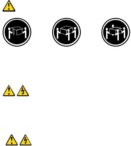
Statement 4:
≥ 18 kg (39.7 lb.) |
≥ 32 kg (70.5 lb.) |
≥ 55 kg (121.2 lb.) |
CAUTION:
Use safe practices when lifting.
Statement 5:
CAUTION:
The power control button on the device and the power switch on the power supply do not turn off the electrical current supplied to the device. The device also might have more than one power cord. To remove all electrical current from the device, ensure that all power cords are disconnected from the power source.
2 

 1
1 


xii ThinkServer TS200 Types 6522, 6523, 6524, 6525, 6526, 6528, 6529, and 6530: Installation and User Guide
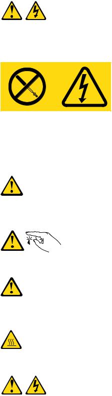
Statement 8:
CAUTION:
Never remove the cover on a power supply or any part that has the following label attached.
Hazardous voltage, current, and energy levels are present inside any component that has this label attached. There are no serviceable parts inside these components. If you suspect a problem with one of these parts, contact a service technician.
Statement 11:
CAUTION:
The following label indicates sharp edges, corners, or joints nearby.
Statement 12:
CAUTION:
The following label indicates a hot surface nearby.
Statement 13:
Safety xiii
DANGER
Overloading a branch circuit is potentially a fire hazard and a shock hazard under certain conditions. To avoid these hazards, ensure that your system electrical requirements do not exceed branch circuit protection requirements. Refer to the information that is provided with your device for electrical specifications.
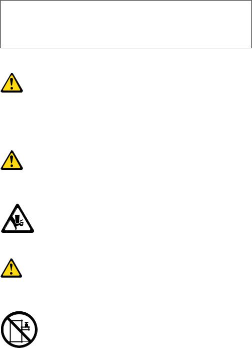
Statement 15:
CAUTION:
Make sure that the rack is secured properly to avoid tipping when the server unit is extended.
Statement 17:
CAUTION:
The following label indicates moving parts nearby.
Statement 26:
CAUTION:
Do not place any object on top of rack-mounted devices.
Attention: This product is suitable for use on an IT power distribution system whose maximum phase to phase voltage is 240 V under any distribution fault condition.
xiv ThinkServer TS200 Types 6522, 6523, 6524, 6525, 6526, 6528, 6529, and 6530: Installation and User Guide

Chapter 1. Introduction
This Installation and User Guide is intended to use with your Lenovo® ThinkServer™ TS200 (Machine Types 6522, 6523, 6524, 6525, 6526, 6528, 6529, and 6530) server. This document contains information about:
vSetting up and cabling the server
vStarting and configuring the server
vInstalling options and replacing customer replaceable units (CRUs)
vSolving problems
The server comes with the ThinkServer EasyStartup DVD to help you configure the hardware, install device drivers, and install the operating system.
The server comes with a limited warranty. For information about the terms of the warranty and getting service and assistance, see the Warranty and Support Information document on the ThinkServer Documentation DVD. To obtain up-to-date information about the server and other Lenovo products, go to: http://www.lenovo.com/thinkserver.
Record information about the server in the following table. You will need this information when you register the server with Lenovo.
Product name |
ThinkServer TS200 |
Machine type |
6522, 6523, 6524, 6525, 6526, 6528, 6529, and 6530 |
Model number |
_____________________________________________ |
Serial number |
_____________________________________________ |
|
|
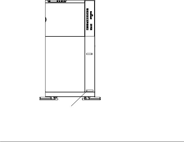
The model number and serial number are on labels on the bottom of the server and on the front, visible through the bezel, as shown in the following illustration.
© Lenovo 2009. Portions © IBM Corp. 2009. |
1 |
|
|
|
|
1 |
Model and machine type |
||
For a list of supported optional devices for the server, go to
http://www.lenovo.com/thinkserver and click the Options tab.
Notices and statements in this document
The caution and danger statements that appear in this document are also in the multilingual Safety Information document, which is on the Lenovo ThinkServer Documentation DVD. Each statement is numbered for reference to the corresponding statement in the Safety Information document.
The following notices and statements are used in this document:
vNote: These notices provide important tips, guidance, or advice.
vImportant: These notices provide information or advice that might help you avoid inconvenient or problem situations.
vAttention: These notices indicate potential damage to programs, devices, or data. An attention notice is placed just before the instruction or situation in which damage could occur.
vCaution: These statements indicate situations that can be potentially hazardous to you. A caution statement is placed just before the description of a potentially hazardous procedure step or situation.
vDanger: These statements indicate situations that can be potentially lethal or extremely hazardous to you. A danger statement is placed just before the description of a potentially lethal or extremely hazardous procedure step or situation.
2 ThinkServer TS200 Types 6522, 6523, 6524, 6525, 6526, 6528, 6529, and 6530: Installation and User Guide

Related documentation
The Lenovo ThinkServer Documentation DVD contains documentation for the server in Portable Document Format (PDF). The Lenovo ThinkServer Documentation DVD requires the Adobe® Reader 5.0 (or later) or xpdf, which comes with Linux® operating systems.
The following table describes the content and location of documentation that is provided with your server.
Document |
Description |
Location |
|
|
|
Read Me First |
This document directs you to the |
printed, provided |
|
ThinkServer Documentation DVD for |
in server |
|
complete warranty and support information. |
packaging |
|
|
|
Important Notices |
This document includes safety and legal |
printed, provided |
|
notices that you are expected to read |
in server |
|
before using the server. |
packaging |
|
|
|
Hardware Maintenance |
This document provides diagnostic |
Lenovo Support |
Manual |
information, parts listing, and replacement |
Web site: |
|
procedures for all field replaceable units |
http:// |
|
(parts replaced by trained service |
www.lenovo.com/ |
|
personnel) as well as all customer |
support |
|
replaceable units (CRUs). |
|
|
|
|
Warranty and Support |
This document includes the warranty |
Available on the |
Information |
statement and information about how to |
ThinkServer |
|
contact Lenovo Support. |
Documentation |
|
|
DVD |
|
|
|
Safety Information |
This document includes translations of all |
Available on the |
|
of the safety statements used in the |
ThinkServer |
|
ThinkServer documentation. |
Documentation |
|
|
DVD |
|
|
|
Chapter 1. Introduction 3
4 ThinkServer TS200 Types 6522, 6523, 6524, 6525, 6526, 6528, 6529, and 6530: Installation and User Guide
Chapter 2. Server setup roadmap
The installation process varies depending on the configuration of the server when it was delivered. In some cases, the server is fully configured and just needs to be connected to power and the network and started. In other cases, the server needs to have hardware features installed, requires hardware and firmware configuration, and requires the operating system to be installed.
Table 1. Server setup roadmap
Task |
Where to find information |
|
|
Unpack |
Chapter 3, “What is included with your server,” on page 7 |
|
|
Install hardware |
Chapter 5, “Installing and replacing optional devices,” on page 29 |
features |
Chapter 6, “Installing and replacing customer replaceable units,” on |
|
page 73 |
|
|
Connect Ethernet cable |
“Rear view” on page 18 |
and power cords to |
|
network and power |
|
connectors |
|
|
|
Start the server to |
“Turning on the server” on page 26 |
verify operation |
|
|
|
Review UEFI settings |
“Starting the Setup Utility” on page 110 |
and customize as |
|
needed |
|
|
|
Configure RAID |
“RAID controllers” on page 115 |
controllers and arrays |
|
|
|
Check for firmware |
“Using the EasyUpdate Firmware Updater tool” on page 123 |
updates |
|
|
|
Install operating system |
“Using the ThinkServer EasyStartup program” on page 117 |
and basic drivers |
|
|
|
Install any additional |
Refer to the instructions that came with the hardware option. |
drivers needed for |
|
added features |
|
|
|
Configure Ethernet |
See the operating system help. This step is not required if the |
settings in operating |
operating system was installed using the ThinkServer EasyStartup |
system |
program. |
|
|
Test Integrated |
“Using the Integrated Management Module” on page 123 |
Management Module |
|
(requires the IMM |
|
Premium option) |
|
|
|
Install remote |
“Installing ThinkServer EasyManage software” on page 126 |
management |
|
applications |
|
|
|
Install applications |
Refer to the documentation that accompanies the applications that |
|
you want to install. |
|
|
© Lenovo 2009. Portions © IBM Corp. 2009. |
5 |
6 ThinkServer TS200 Types 6522, 6523, 6524, 6525, 6526, 6528, 6529, and 6530: Installation and User Guide
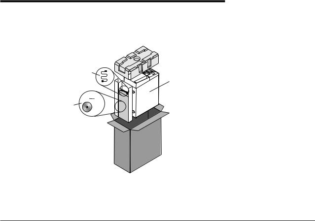
Chapter 3. What is included with your server
The TS200 server package includes the server, power cords, the ThinkServer
Documentation DVD, and software media.
|
|
|
|
|
|
|
|
|
|
|
|
|
|
|
|
|
|
|
|
|
|
|
|
|
|
|
|
|
|
|
|
|
|
|
|
|
|
|
|
|
|
|
|
|
|
|
|
|
|
|
|
|
|
|
|
|
|
|
|
|
|
|
|
|
|
|
|
|
|
|
|
|
|
|
|
|
|
|
|
|
|
|
|
|
|
|
|
1 |
|
Server |
||||||||
2 |
|
Power cords |
||||||||
3 |
|
Documentation and software media |
||||||||
Features and technologies
The TS200 server offers the following features and technologies:
vUEFI-compliant server firmware
The server firmware offers several features, including Unified Extensible Firmware Interface (UEFI) 2.1 compliance, enhanced RAS capabilities, and BIOS compatibility support. UEFI replaces the basic input/output system (BIOS) and defines a standard interface between the operating system, platform firmware, and external devices. UEFI-compliant servers are capable of starting UEFI-compliant operating systems, BIOS-based operating systems, and BIOS-based adapters as well as UEFI-compliant adapters.
Note: The server does not support DOS (Disk Operating System).
vSystems-management capabilities
The integrated management module (IMM) combines service processor functions, video controller, and remote presence function in a single chip. The IMM provides advanced service-processor control, monitoring, and alerting function. If an environmental condition exceeds a threshold or if a system component fails, the IMM lights LEDs to help you diagnose the problem, records the error in the event log, and alerts you to the problem. The IMM also provides a virtual presence capability for remote server management capabilities. The IMM provides remote server management through industry-standard interfaces:
–Intelligent Platform Management Interface (IPMI) version 2.0
–Simple Network Management Protocol (SNMP) version 3
–Common Information Model (CIM)
–Web browser
© Lenovo 2009. Portions © IBM Corp. 2009. |
7 |
vRemote presence capability and blue-screen capture
The remote presence feature provides the following functions:
–Remotely viewing video with graphics resolutions up to 1600 x 1200 at 85 Hz, regardless of the system state
–Remotely accessing the server, using the keyboard and mouse from a remote client
–Mapping the CD or DVD drive, diskette drive, and USB flash drive on a remote client, and mapping ISO and diskette image files as virtual drives that are available for use by the server
–Uploading a diskette image to the IMM memory and mapping it to the server as a virtual drive
The blue-screen capture feature captures the video display contents before the IMM restarts the server when the IMM detects an operating-system hang condition. A system administrator can use the blue-screen capture to assist in determining the cause of the hang condition.
vPreboot diagnostics programs
The preboot diagnostics programs are stored on the integrated USB memory. It collects and analyzes system information to aid in diagnosing server problems. The diagnostics programs collect the following information about the server:
–System configuration
–Network interfaces and settings
–Installed hardware
–Service processor status and configuration
–Vital product data, firmware, and UEFI (formerly BIOS) configuration
–Hard disk drive health
–RAID controller configuration
–Event logs for service processors
The diagnostic programs create a merged log that includes events from all collected logs. The information is collected into a file that you can send to Lenovo service and support. Additionally, you can view the information locally through a generated text report file. You can also copy the log to a removable media and view the log from a Web browser.
For additional information about preboot diagnostics, see the Hardware Maintenance Manual.
vEasyStartup DVD
The ThinkServer EasyStartup program guides you through the configuration of the hardware, the RAID controller, and the installation of the operating system and device drivers.
vEasyManage DVD
The ThinkServer EasyManage program helps you manage and administer your servers and clients through remote problem notification as well as monitoring and alerting.
vIntegrated network support
The server comes with an integrated dual-port Intel 82574L Gigabit Ethernet controller, which supports connection to a 10 Mbps, 100 Mbps, or 1000 Mbps network. For more information, see “Configuring the Gigabit Ethernet controller” on page 122.
vIntelligent Platform Management Interface (IPMI) 2.0
8 ThinkServer TS200 Types 6522, 6523, 6524, 6525, 6526, 6528, 6529, and 6530: Installation and User Guide
The command-line interface provides direct access to server management functions through the IPMI 2.0 protocol. Use the command-line interface to issue commands to control the server power, view system information, and identify the server. You can also save one or more commands as a text file and run the file as a script.
vLarge data-storage capacity and hot-swap capability
Some hot-swap server models support four 3.5-inch hot-swap hard disk drives. With the hot-swap feature, you can add, remove, or replace hard disk drives without turning off the server.
vLarge system-memory capacity
The server supports up to 32 GB of system memory when registered DIMMs are installed. The server supports up to 16 GB of memory when unbuffered DIMMs are installed. The memory controller supports error correcting code (ECC) and non-error correcting code for up to 6 industry-standard PC3-8500, or PC3-10600R-999 (single-rank or dual-rank), 1066 and 1333 MHz, DDR3 (third-generation double-data-rate), registered, and unbuffered synchronous dynamic random access memory (SDRAM) dual inline memory modules (DIMMs).
vRedundant connection
The addition of an optional network interface card (NIC) provides a failover capability to a redundant Ethernet connection. If a problem occurs with the primary Ethernet connection, all Ethernet traffic that is associated with the primary connection is automatically switched to the redundant NIC. If the applicable device drivers are installed, this switching occurs without data loss and without user intervention.
vHigh-performance graphics controller
The server comes with an onboard high-performance graphics controller that supports high resolutions and includes many performance-enhancing features for the operating-system environment.
vRedundant connection
The addition of an optional network interface card (NIC) provides a failover capability to a redundant Ethernet connection. If a problem occurs with the primary Ethernet connection, all Ethernet traffic that is associated with the primary connection is automatically switched to the redundant NIC. If the applicable device drivers are installed, this switching occurs without data loss and without user intervention.
vDual-core or quad-core processing
The server supports one Intel Xeon dual-core or quad-core microprocessor.
vRAID support
The server supports an internal RAID SAS Controller, which is required for you to use the hot-swap hard disk drives and to create redundant array of independent disks (RAID) configurations.
vTCP/IP offload engine (TOE) support
The Ethernet controllers in the server support TOE, which is a technology that offloads the TCP/IP flow from the microprocessors and I/O subsystem to increase the speed of the TCP/IP flow. When an operating system that supports TOE is running on the server and TOE is enabled, the server supports TOE operation. See the operating-system documentation for information about enabling TOE.
Note: As of the date of this document, the Linux® operating system does not support TOE.
Chapter 3. What is included with your server 9

Specifications
The following information is a summary of the features and specifications of the server. Depending on the server model, some features might not be available, or some specifications might not apply.
Table 2. Features and specifications
Microprocessor:
vSupports one Intel® Xeon® 3400 series quad-core microprocessor
vDesigned for LGA 1156 socket
vScalable up to four cores
v32 KB instruction cache, 32 KB data cache, and up to 8 MB cache that is shared among the cores
vSupport for Intel Extended Memory 64 Technology (EM64T)
Note:
vUse the Setup Utility to determine the type and speed of the microprocessor.
vFor a list of supported microprocessors, see http://www.lenovo.com/thinkserver/ and click the Options tab.
Memory:
vMinimum: 1 GB
vMaximum: 32 GB
–16 GB using unbuffered DIMMs (UDIMMs)
–32 GB using registered DIMMs (RDIMMs)
vTypes: PC3-8500 or PC3-10600R-999 (single-rank or double-rank), 1066, and 1333 MHz, ECC, DDR3 registered or unbuffered SDRAM DIMMs only
vConnectors: Six dual inline memory module (DIMM) connectors, two-way interleaved
vSupports:
–1 GB, 2 GB, and 4 GB (when available) unbuffered DIMMs
–1 GB, 2 GB, 4 GB, and 8 GB (when available) registered DIMMs
SATA optical drives:
vUltraSlim DVD-ROM combo (optional)
vMulti-burner (optional)
Hard disk drive expansion bays (depending on the model):Up to four 3.5-inch hot-swap SAS or up to four 3.5-inch hot-swap SATA hard disk drive bays
Up to six expansion slots (depending on model):
vSix expansion slots on the system board
vTwo PCI Express Gen2 x8 slots (x8 links)
vOne PCI Express Gen2 x4 slot (x4 link)
vTwo PCI 32-bit/33 MHz slots
vOne PCI Express Gen2 x4 slot (x4 electrical and mechanical) for the ServeRAID BR10il adapter
Power supply:
One 401-watt power supply or two 430-watt high efficiency power supply
Fans: The server comes standard with three speed-controlled fans.
Integrated functions:
vIntegrated management module (IMM), which provides service processor control and monitoring functions, video controller, and (when the optional virtual media key is installed) remote keyboard, video, mouse, and remote hard disk drive capabilities
vIntel 82574L Gb Ethernet controller with TCP/IP Offload Engine (TOE) and Wake on LAN support
vSeven Universal Serial Bus (USB) 2.0 ports (two front and four rear of the chassis), one internal for the optional USB Hypervisor key
vTwo Ethernet ports
vFour-port integrated SATA controller
vIntegrated Trusted Platform Module (TPM) support
vOne serial port
vOne VGA port
10 ThinkServer TS200 Types 6522, 6523, 6524, 6525, 6526, 6528, 6529, and 6530: Installation and User Guide

Table 2. Features and specifications (continued)
RAID controllers:
vServeRAID BR10il
vServeRAID-MR10i
vServeRAID-M1015
vServeRAID M5015
vServeRAID MR10is VAULT
Acoustical noise emissions:
vSound power, idling: 6.5 bels maximum
vSound power, operating: 6.5 bels maximum
Environment:
vAir temperature:
–Server on: 10°C to 35°C (50.0°F to 95.0°F); altitude: 0 to 914.4 m (3000 ft)
–Server on: 10°C to 32°C (50.0°F to 89.6°F); altitude: 914.4 m (3000 ft) to 2133.6 m (7000.0 ft)
–Server off: 10°C to 43°C
(50°F to 109.4°F); maximum altitude: 2133.6 m (7000.0 ft)
–Shipping: -40°C to 60°C (-104°F to 140°F)
vHumidity:
–Server on: 8% to 80%
–Server off: 8% to 80%
vParticulate contamination:
Attention: Airborne particulates and reactive gases acting alone or in combination with other environmental factors such as humidity or temperature might pose a risk to the server.
Video controller (integrated into IMM):
vMatrox G200
vCompatible with SVGA and VGA
v128 MB SDRAM video memory
Note: The maximum video resolution is 1280 x 1024
Size:
vHeight: 448 mm (17.63 inches)
vDepth: 483 mm (19.01 inches)
vWidth: 265 mm (10.43 inches)
vMaximum weight: 20.8 kg (45.86 lb) when fully configured
Heat output:
Approximate heat output:
vMinimum configuration: 630 BTU per hour (185 watts)
vMaximum configuration: 1784 BTU per hour (523 watts)
Electrical input:
vSine-wave input (50 / 60 Hz) required
vInput voltage low range:
–Minimum: 100 V ac
–Maximum: 127 V ac
vInput voltage high range:
–Minimum: 200 V ac
–Maximum: 240 V ac
vInput kilovolt-amperes (kVA), approximately:
–Minimum: 0.102 kVA
–Maximum: 0.55 kVA
Notes:
1.Power consumption and heat output vary depending on the number and type of optional features installed and the power-management optional features in use.
2.The sound levels were measured in controlled acoustical environments according to the procedures specified by the American National Standards Institute (ANSI) S12.10 and ISO 7779 and are reported in accordance with ISO 9296. Actual sound-pressure levels in a given location might exceed the average values stated because of room reflections and other nearby noise sources. The noise emission level stated is the declared (upper limit) sound-power level, in bels, for a random sample of system.
3.There is no keyboard connector or mouse connector on the server. You can connect a USB keyboard and USB mouse to the server by using the USB connectors.
Software
Lenovo provides software to help get your server up and running.
EasyStartup
The ThinkServer EasyStartup program simplifies the process of your RAID controller and installing supported Microsoft® Windows and Linux operating systems and device drivers on your server. The EasyStartup program is provided with your server on DVD. The DVD is self starting (bootable). The user guide for the EasyStartup program is on the DVD and can be accessed directly from the program interface. For additional information, see “Using the ThinkServer EasyStartup program” on page 117.
EasyManage
The ThinkServer EasyManage Core Server provides centralized hardware and software inventory management and secure automated system management through a centralized console. The ThinkServer EasyManage Agent enables other clients on the network to be managed by the centralized console. The ThinkServer EasyManage Core Server is supported on Microsoft Windows Server 2008 (32-bit) products. The ThinkServer EasyManage Agent is supported on 32-bit and 64-bit Windows, Red Hat, and SUSE operating systems.
Chapter 3. What is included with your server 11

Reliability, availability, and serviceability
Three important server design features are reliability, availability, and serviceability (RAS). The RAS features help to ensure the integrity of the data that is stored on the server, the availability of the server when you need it, and the ease with which you can diagnose and correct problems.
The server has the following RAS features:
vAdvanced Configuration and Power Interface (ACPI)
vAdvanced Desktop Management Interface (DMI) features
vAutomatic error retry or recovery
vAutomatic memory downsizing on error detection
vAutomatic restart on nonmaskable interrupt (NMI)
vAutomatic Server Restart (ASR) logic supporting a system restart when the operating system becomes unresponsive
vAutomatic server restart after a power failure, based on the UEFI setting
vAvailability of microcode level
vAutomatic BIOS Recovery (ABR)
vBuilt-in, menu-driven setup, system configuration, and redundant array of independent disks (RAID) configuration
vBuilt-in monitoring for fan, power, temperature, and voltage
vCooling fans with speed-sensing capability
vCustomer support center that is available 24 hours a day, 7 days a week1
vDiagnostic support of ServeRAID adapters
vError codes and messages
vError correcting code (ECC) double-data-rate (DDR) synchronous dynamic random access memory (SDRAM) with serial presence detect (SPD)
vError logging of POST failures
vHot-swap SAS hard disk drives
vIntegrated Ethernet controllers
vIntelligent Platform Management Interface (IPMI) 2.0
vKey-lock support for physical security
vMemory change messages posted to the error log
vPower-on self-test (POST)
vHardware Failure Prediction alerts
vRead-only memory (ROM) checksums
vRedundant Ethernet capabilities (requires an optional Ethernet adapter) with failover support
vStandby voltage for systems-management features and monitoring
vSystem auto-configuring from the configuration menu
vSystem-error LED on the front bezel and diagnostics LEDs on the system board
vUpgradeable microcode for POST, UEFI, and read-only memory (ROM) resident code, locally or over a LAN
vVPD: includes serial-number information and replacement part numbers, stored in nonvolatile memory, for easier remote maintenance
1.Service availability will vary by country. Response time varies; may exclude holidays.
12 ThinkServer TS200 Types 6522, 6523, 6524, 6525, 6526, 6528, 6529, and 6530: Installation and User Guide
v Wake on LAN capability
Chapter 3. What is included with your server 13
14 ThinkServer TS200 Types 6522, 6523, 6524, 6525, 6526, 6528, 6529, and 6530: Installation and User Guide
Loading...