

Page 1

Version 2.1
English
Leica TPS400 Series
User Manual
Page 2

Electronical Total Station
Congratulations on your purchase of a new
Leica Geosystems Total Station.
This manual contains important safety
directions as well as instructions for
setting up the product and operating it.
Refer to "Safety Directions" for further
information.
Read carefully through the User Manual
before you switch on the product.
Product identification
The model and the serial number of your product is
indicated on the type plate.
Enter the model and the serial number in your
manual and always refer to this information when
you need to contact your agency or Leica Geosystems authorized service workshop.
Type: ____________ Serial no.: ____________
Symbols used in this manual
The symbols used in this User Manual have the
following meanings:
DANGER
m
Indicates an imminently hazardous situation
which, if not avoided, will result in death or serious
injury.
WARNING
m
Indicates a potentially hazardous situation
or an unintended use which, if not avoided, could
result in death or serious injury.
CAUTION
m
Indicates a potentially hazardous situation
or an unintended use which, if not avoided, may
result in minor or moderate injury and / or appreciable material, financial and environmental
damage.
Important paragraphs which must be
adhered to in practice as they enable the product to
be used in a technically correct and efficient manner.
TPS400-2.1.0en
2
Page 3

Trademarks
• Windows is a registered trademark of Microsoft
Corporation
• Bluetooth is a registered trademark of Bluetooth
SIG, Inc.
All other trademarks are the property of their respective owners.
3
TPS400-2.1.0en
Page 4

Contents - Overview
Introduction.................................................... 8
Operating the product............................. 17
Measuring Preparation / Setting up.. 25
FNC Key.......................................................... 41
Programs ....................................................... 45
Settings........................................................... 77
EDM Settings ............................................... 82
File Management........................................ 87
Start-up sequence ..................................... 90
Calibrations .................................................. 91
COMM Parameters .................................... 95
Data Transfer ............................................... 96
System Info................................................... 97
Care and Storage....................................... 98
TPS400-2.1.0en
Safety Directions...................................... 107
Technical Data........................................... 130
Index............................................................... 140
4
Contents - Overview
Page 5

Contents
Introduction.................................................... 8
Special features............................................... 9
Important parts............................................... 10
Technical terms and abbreviations ............ 11
Area of applicability....................................... 14
Installation on the PC ..................................... 14
Program content............................................. 14
Power Supply................................................. 16
Operating the product............................. 17
Keypad ............................................................ 17
Fixed keys ...................................................... 18
Trigger key...................................................... 18
Distance measurement ................................ 19
Softkeys .......................................................... 22
Symbols .......................................................... 23
Status symbol "EDM type" ............................. 23
Status symbol "Battery capacity" ................... 23
Status symbol "Compensator" ....................... 23
Menu tree........................................................ 24
Measuring Preparation / Setting up.. 25
Unpacking....................................................... 25
Inserting / Replacing Battery ....................... 26
Contents
External power supply for total
.............................................................. 27
station
Setting up the tripod...................................... 28
Centring with laser plummet,
coarse level-up .............................................. 30
Fine tuning in the horizontal with the
electronic bubble ........................................... 31
Laser intensity................................................ 32
Hints for positioning ...................................... 32
Input mode - method 1 ................................. 33
Input mode - method 2 ................................. 33
Edit mode........................................................ 34
Erasing characters ......................................... 34
Inserting characters........................................ 35
Numerical and Alphanumerical input......... 36
Pointsearch .................................................... 38
Wildcard search............................................. 39
Measuring....................................................... 40
FNC Key.......................................................... 41
Light On /Off................................................... 41
Level/Plummet ............................................... 41
IR/ RL Toggle................................................. 41
5
TPS400-2.1.0en
Page 6

Laser Pointer.................................................. 41
Free-Coding ................................................... 41
Units................................................................. 41
Target Offset .................................................. 42
Height Transfer.............................................. 43
Programs ....................................................... 45
Application pre-settings................................ 45
Setting job ...................................................... 45
Setting Station................................................ 46
Orientation...................................................... 47
Applications .................................................... 51
Introduction .................................................... 51
Surveying ....................................................... 51
Stake out ........................................................ 52
Free Station.................................................... 55
Reference Line............................................... 61
Tie Distance ................................................... 68
Area (plan) ..................................................... 70
Remote Height ............................................... 71
Construction ................................................... 72
Coding............................................................. 74
Settings........................................................... 77
EDM Settings ............................................... 82
File Management........................................ 87
Start-up sequence..................................... 90
Calibrations .................................................. 91
Line-of-sight error (Hz-collimation)............. 92
V-Index (Vertical index error)...................... 92
COMM Parameters .................................... 95
Data Transfer ............................................... 96
System Info................................................... 97
Care and Storage....................................... 98
Transport ........................................................ 98
In the field....................................................... 98
Inside vehicle ................................................. 99
Shipping ......................................................... 99
Storage............................................................ 99
Batteries ....................................................... 100
Cleaning ....................................................... 100
Checking and adjusting.............................. 102
Tripod ........................................................... 102
Circular level ................................................ 102
TPS400-2.1.0en
6
Contents
Page 7

Circular level on the tribrach ........................ 103
Laser plummet ............................................. 103
Reflectorless EDM ....................................... 104
Safety Directions...................................... 107
Intended Use................................................ 107
Permitted use ............................................... 107
Adverse use ................................................. 107
Limits of Use ................................................ 108
Responsibilities............................................ 109
International Waranty, Software Licence
Agreement.................................................... 110
Hazards of Use............................................ 111
Laser classification...................................... 115
Integrated Distancer, Invisible Laser............ 115
Electronic Guide Light EGL.......................... 122
Laser plummet ............................................. 123
Electromagnetic Compatibility EMC ........ 126
FCC Statement (Applicable in U.S.) ........ 128
Technical Data........................................... 130
Atmospheric correction .............................. 136
Reduction formulae ...................................... 138
Index............................................................... 140
Contents
7
TPS400-2.1.0en
Page 8
Introduction
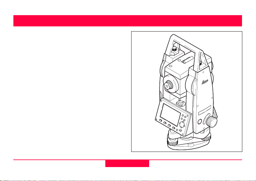
The Leica Geosystems TPS400 is a high-quality
electronic total station designed for the construction
site.
Its innovative technology makes the daily surveying
jobs easier.
The product is ideally suited for simple construction
surveys and setting out tasks.
The easy operation of the product functions can be
learned without problems in no time.
TC400Z1
TPS400-2.1.0en
8
Introduction
Page 9

Special features
• Easy and quickly to learn !
• Interactive keys; with large and clear LCD.
• Small, light-weight and easy-to-use.
• Measurements without reflector with the integrated visible laser beam (TCR products).
• Additional trigger key on side cover.
• Continuous drives for horizontal and vertical
angles (tangent screws).
• With laser plummet as standard.
Introduction
9
TPS400-2.1.0en
Page 10
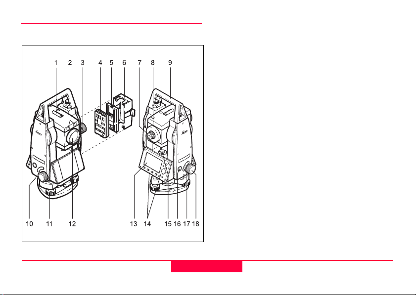
Important parts
1) Optical sight
2) Integrated guide light EGL (optional)
3) Vertical drive
4) Battery
5) Battery stand for GEB111
6) Battery cover
7) Eyepiece; focussing graticule
8) Focussing telescope image
9) Detachable carrying handle with mounting
screws
10) Serial interface RS232
11) Foot screw
12) Objective with integrated Electronic Distance
Measurement (EDM); Beam exit
13) Display
14) Keyboard
15) Circular level
16) On/Off key
17) Trigger key
18) Horizontal drive
TC400Z2
TPS400-2.1.0en
10
Introduction
Page 11
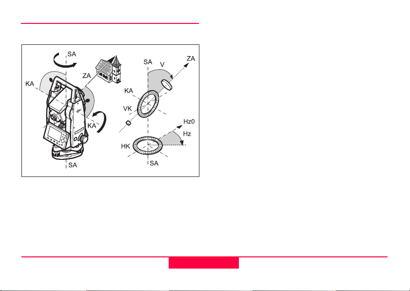
Technical terms and abbreviations
TC400Z3
ZA = Line of sight / collimation axis
Telescope axis = line from the reticle to the centre
of the objective.
SA = Standing axis
Vertical rotation axis of the telescope.
KA = Tilting axis
Horizontal rotation axis of the telescope (Trunion
axis).
V = Vertical angle / zenith angle
VK = Vertical circle
With coded circular division for reading the V-angle.
Hz = Horizontal direction
HK = Horizontal circle
With coded circular division for reading the Hzangle.
Introduction
11
TPS400-2.1.0en
Page 12
Standing axis inclination
Angle between plumb line and
standing axis. Standing axis tilt is
not an product error and is not eliminated by measuring in both faces.
Any possible influence it may have
on the Hz-direction resp. V-angle is
elliminated by the dual axis
compensator.
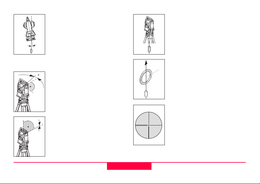
Line-of-sight error (Hz-collimation)
The line-of-sight error is the deviation from the perpendicular
between tilting axis and line-ofsight. This could be eleminated by
measuring in both faces.
V-Index (Vertical index error)
With horizontal line-of-sight the Vcircle reading should be exactly
90°(100gon). The deviation from
this values is termed V-index (i).
Plumb line / Compensator
Direction of gravity. The compensator defines the plumb line within
the product.
Zenith
Point on the plumb line above the
observer.
Reticle
Glass plate within the telescope
with reticle.
TPS400-2.1.0en
12
Introduction
Page 13
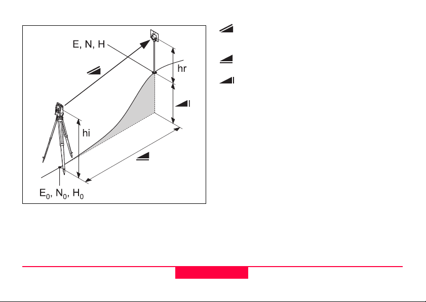
TC400Z4
Indicated meteorological corrected slope
distance between product tilting axis and
centre of prism/laser spot (TCR).
Indicated meteorological corrected horizontal distance.
Height difference between station and
target point.
hr Reflector height above ground
hi product height above ground
E0 Station coordinate (Easting)
N0 Station coordinate (Northing)
H0 Station height
E Easting of target point
N Northing of target point
H Height of target point
Introduction
13
TPS400-2.1.0en
Page 14

Area of applicability
This User Manual is valid for all products of the
TPS400 Series.
TC products are equipped with an invisible infrared
EDM and TCR products with a visible red laser for
reflectorless measuring.
Sections only valid for TCR products are marked
accordingly.
PC Program Package
Leica Geo Office Tools (LGO-Tools)
The program package LGO-Tools is used for the
data exchange between the Total Station and the
PC. It contains several auxiliary programs in order to
support your use of the product.
Installation on the PC
The installation program can be found on the CDROM supplied. Please note that LGO-Tools can
only be installed on computers with MS Windows
98, 2000 or XP operating systems.
Any previous versions of LGO-Tools on
your computer must be uninstalled first before
installing the new version.
For the installation call program "setup.exe" in the
directory \LGO-Tools on the CD-ROM and follow
the input instructions of the installation program.
Program content
After successful installation the following programs
appear:
TPS400-2.1.0en
14
Introduction
Page 15

Tools
• Data Exchange Manager
For data exchange of coordinates, measurements, codelists and output formats between
product and PC.
• Coordinate Editor
Import/Export as well as creating and
processing of coordinate files.
• Codelist Manager
For creating and processing of codelists.
• Software Upload
For loading system software and EDM-software.
For EDM Software upload only LGO/LGO-
Tools Software Version 3.0 or higher must be used
for error free operation.
Not using the correct upload Software can permanently damage the instrument.
Before the Software Upload, always insert a
charged battery into the product.
• Format Manager
For creating of own, special formatted data
output files.
• Configuration Manager
Import/Export as well as creating of product
configuration.
For more informationen about LGO-Tools
refer to the comprehensive Online Help.
Introduction
15
TPS400-2.1.0en
Page 16
Power Supply
Use the Leica Geosystems batteries, chargers and
accessories or accessories recommended by Leica
Geosystems to ensure the correct functionality of
the product.
Power for the product can be supplied either internally or externally. An external battery is connected
to the product using a LEMO cable.
• Internal battery:
One GEB111 or 121 battery fit in the battery
compartment.
• External battery:
One GEB171 battery connected via cable.
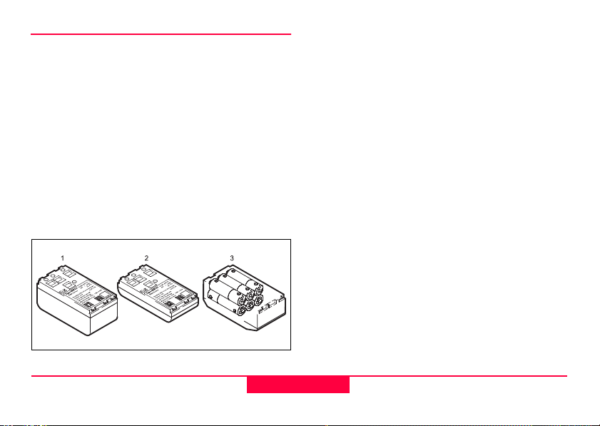
1 GEB121
2 GEB111
3 Single cells in the battery adapter GAD39
Your Leica Geosystems product is powered by
rechargeable plug-in batteries. For this product, we
recommend the basic battery (GEB111) or the Pro
battery (GEB121). Optionally six single cells can be
used with the GAD39 battery adapter.
Six single cell batteries (1.5 V each) supply 9 Volts.
The voltmeter on the product is designed for a
voltage of 6 Volts (GEB111/ GEB121).
The battery charge is not displayed correctly
when using single cells. Use the single cells with the
battery adapter as emergency power supply. The
advantage of the single cells is in a lower rate of
discharge even over long periods.
TPS400-2.1.0en
16
Introduction
Page 17
Operating the product
The on / off key is located on the side cover of the
TPS400.
All shown displays are examples. It is
possible that local software versions are different to
the basic version.
Keypad
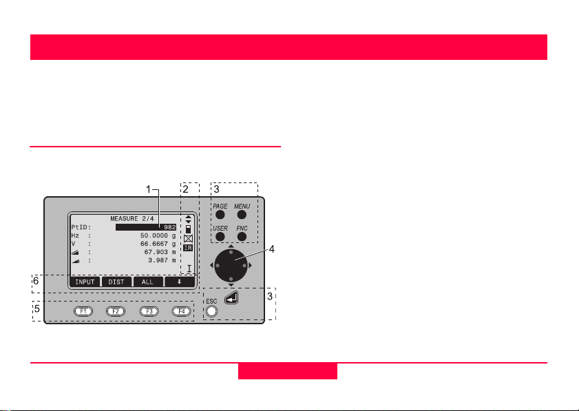
TC400Z5
1) Focus
Actively measured field.
2) Symbols
3) Fixed keys
Keys with firmly assigned functions.
4) Navigation keys
Control of input bar in edit and input mode or
control of focus bar.
5) Function keys
Are assigned the variable functions displayed at
the bottom of the screen.
6) Softkey bar
Displays functions that can be called up with the
function keys.
Operating the product
17
TPS400-2.1.0en
Page 18

Fixed keys
[PAGE] Scrolls to next page when a dialogue-
consists of several pages.
[MENU] Accesses programs, settings, the data
manager, adjustments, communications parameters,system information
and data transfer.
[USER] Key, programmable with function from
the FNC menu.
[FNC] Quick-access to measurement-
supporting functions.
[ESC] Quit a dialog or the edit mode with acti-
vation of the "previous" value. Return to
next heigher level.
Confirm an input; continue to the next
field.
Trigger key
The measurement trigger (see "Most important
elements"; index 17) has three settings (ALL,DIST,
OFF).
The key can be activated in the configuration menu.
TPS400-2.1.0en
18
Operating the product
Page 19

Distance measurement
A laser distancer (EDM) is incorporated into the
products of the TPS400 series.
In all versions, the distance can be determined by
using an invisible infrared beam which emerges
coaxially from the telescope objective.
Measurements to strongly reflecting
targets such as to traffic lights in infrared mode
without prism should be avoided. The measured
distances may be wrong or inaccurate.
For applications without reflector, the TCR-version
also use a visible red laser beam which emerges
in the same manner. A special arrangement of the
EDM, and appropriate arrangement of the beam
paths, enable ranges of over five kilometres to be
attained with standard prisms.
Miniprisms, 360° reflectors and reflector tapes can
also be used, and measurement is also possible
without a reflector.
When a distance measurement is trig-
gered, the EDM measures to the object which is
in the beam path at that moment.
If e.g. people, cars, animals, swaying branches, etc.
cross the laser beam while a measurement is being
taken, a fraction of the laser beam is reflected and
may lead to incorrect distance values.
Avoid interrupting the measuring beam while taking
reflectorless measurements or measurements using
reflective foils. Measurements to prism reflectors are
only critical if an object crosses the measuring beam
at a distance of 0 to 30m and the distance to be
measured is more than 300m.
In practice, because the measuring time is very
short, the user can always find a way of avoiding
these critical situations.
Operating the product
19
TPS400-2.1.0en
Page 20
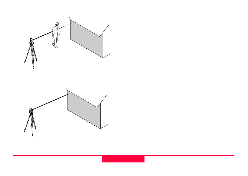
Incorrect result
Correct result
TC400Z6
TC400Z7
Reflectorless
Be sure that the laser beam is not reflected
by anything close to the line of sight (e.g. highly
reflective objects).
When a distance measurement is triggered,
the EDM measures to the object which is in the
beam path at that moment. In case of temporary
obstruction (e.g. a passing vehicle, heavy rain, fog
or snow) the EDM may measure to the obstruction.
When measuring longer distances, any
divergence of the red laser beam from the line of
sight might lead to less accurate measurements.
This is because the laser beam might not be
reflected from the point at which the crosshairs are
pointing.
Therefore, it is recommended to verify that the Rlaser is well collimated with the telescope line of
sight (refer to the chapter "Checking and adjusting").
Do not measure with two products to the
same target simultaneously.
TPS400-2.1.0en
20
Operating the product
Page 21

Red laser to prisms
Accurate measurements to prisms should
be made with the standard program (Infrared mode).
Red laser to reflector tape
The visible red laser beam can be used to measure
to reflective foils, also. To guarantee the accuracy
the red laser beam must be perpendicular to the
reflector tape and it must be well adjusted (refer to
the chapter "Checking and adjusting").
Make sure the additive constant belongs to
the selected target (reflector).
Operating the product
21
TPS400-2.1.0en
Page 22
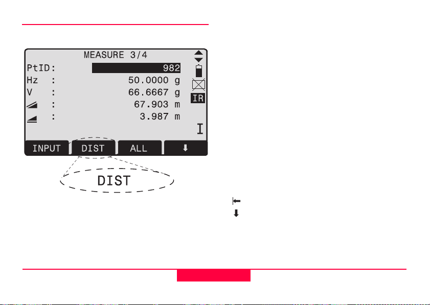
Softkeys
TC400Z8
Under softkeys, a selection of commands and functions is listed at the bottom of the screen. They can
be activated with the corresponding function keys.
The available scope of each function depends on
the applications / functions currently active.
General softkeys:
[ALL] Starts distance and angle measure-
[DIST] Starts distance and angle measure-
[REC] Saves displayed values.
[ENTER] Deletes current value in the display and
[ENH] Opens the coordinate input mode.
[LIST] Displays the list of available points.
[FIND] Starts the search for the point entered.
[EDM] Displays EDM settings.
[IR/RL] Toggles between infrared and reflector-
[PREV] Back to last active dialog.
[NEXT] Continue to next dialog.
[OK] Set displayed message or dialog and
cationspecific buttons in the relevant sections.
ments and saves measured values.
ments without saving measured values.
is ready for the input of a new value.
less measurement modes.
Returns to highest softkey level.
To next softkey level.
quit dialog.
Find further information about menu/appli-
TPS400-2.1.0en
22
Operating the product
Page 23
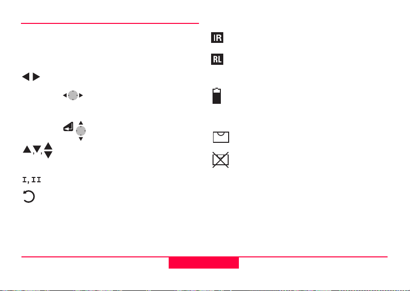
Symbols
Depending on software version different symbols
are displayed indicating a particular operating
status.
A double arrow indicates choice fields.
Using the navigation keys the
desired parameter can be
selected.
Quits a selection with the enter
key or the navigation keys.
Indicates that several pages are available which can be selected with
[PAGE].
Indicates telescope position I or II.
Indicates that Hz is set to "left side angle
measurement" (anti-clockwise).
Status symbol "EDM type"
Infrared EDM (invisible) for measuring
to prisms and reflective targets.
Reflectorless EDM (visible) for
measuring to all targets.
Status symbol "Battery capacity"
The battery symbol indicates the level of
the remaining battery capacity (75% full
shown in the example).
Status symbol "Compensator"
Compensator is on.
Compensator is off.
Operating the product
23
TPS400-2.1.0en
Page 24
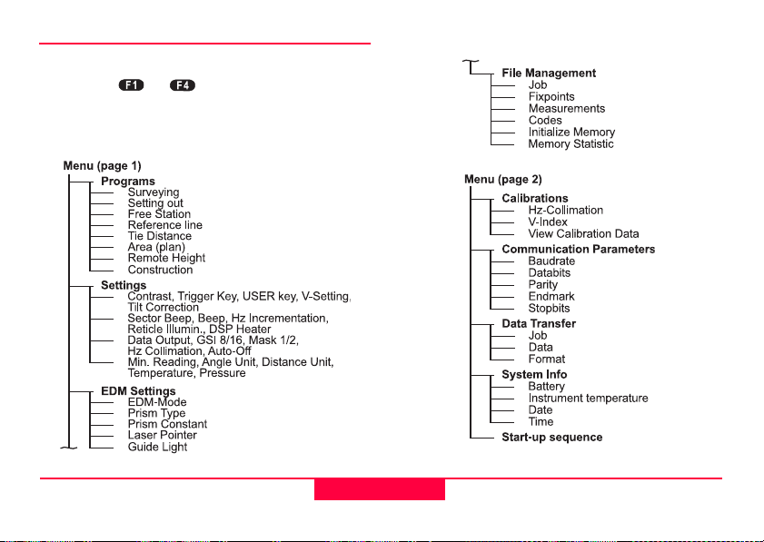
Menu tree
-
[MENU] > Confirm menu selection.
[PAGE] Scroll to next page.
Depending on user interface sequence and
arrangement of menu items may be different.
TPS400-2.1.0en
TC400Z9
24
TC400Z10
Operating the product
Page 25
Measuring Preparation / Setting up
Ku
rza
n
l
e
i
t
u
n
g
T
C3
0
0
jkm
kd
kjo
d
ko
lmd
lko
m
ö
mlko
k
klko
klko
d
klkd
i
ü
k9 o
jo
ko
ko
kd
o
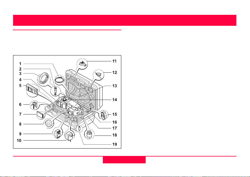
Unpacking
Remove TPS400 from transport case and check for
completeness:
Measuring Preparation /
TC400Z11
25
1) Data cable (optional)
2) Zenith eyepiece or eyepiece for steep angles
(optional)
3) Counterweight for eyepiece for steep angles
(optional)
4) Removable tribrach (optional)
5) Battery charger and accessories (optional)
6) Two Allen keys each, Adjusting pins
7) Battery GEB111 (optional)
8) Sun filter (optional)
9) Battery GEB121 (optional)
10) Mains adapter for battery charger (optional)
11) Spacing bracket GHT 196 for product height
meter (optional)
12) product height meter GHM 007 (optional)
13) Mini prism rod (optional)
14) Total station
15) Mini prism + holder (optional)
16) Mini target plate (only for TCR products)
17) User Manual
18) Protective cover / Lens hood
19) Tip for mini prism (optional)
TPS400-2.1.0en
Page 26
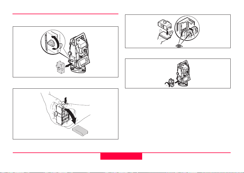
Inserting / Replacing Battery
1. Remove battery holder.
2. Remove battery.
TPS400-2.1.0en
TC400Z12
TC400Z13
3. Insert battery into battery holder.
4. Insert battery holder into product.
Insert battery correctly (note pole markings
on the inside of the battery holder). Check and insert
battery holder true to side into the housing.
• To charge the battery refer to chapter "Charging
the batteries".
• For the type of battery refer to chapter "Technical data".
When using the GEB121 battery, remove the
spacer for the GEB111 from the battery compartment.
26
Measuring Preparation /
TC400Z14
TC400Z15
Page 27
Primary use/charging
• The batteries must be charged prior to using for
the first time because it is delivered with an
energy content as low as possible.
• For new batteries or batteries that have been
stored for a long time (> three months), it is
effectual to make 2 - 5 charge/discharge cycles.
• The permissible temperature range for charging
is between 0°C to +35°C / +32°F to +95°F. For
optimal charging we recommend a low ambient
temperature of +10°C to +20°C / +50°F to
+68°F.
Operation/Discharging
The batteries can be operated from -20°C to
+55°C/-4°F to +131°F.
Low operating temperatures reduce the capacity
that can be drawn; very high operating temperatures
reduce the service life of the battery.
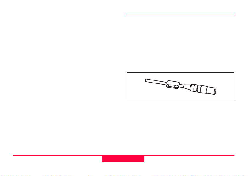
External power supply for total station
To meet the conditions stipulated for electromagnetic acceptability when powering the TPS400 from
an external source, the supply cable used must be
equipped with a ferrite core.
The Lemo plug with the ferrite core always
has to be attached at the product side.
TC400Z16
The cables supplied along with your product include
a ferrite core as standard.
If you are using older cables without ferrite core, it's
necessary to attach ferrite cores to the cable.
If you need additional ferrite cores, please contact
your local Leica Geosystems agency. The sparepart number of the ferrite core is 703 707.
Measuring Preparation /
27
TPS400-2.1.0en
Page 28
TC400Z17
For assembling open up one ferrite core and clip it
around the supply cable, about 2cm away from the
Lemo plug, before using the supply cable for the first
time together with a TPS400 product.
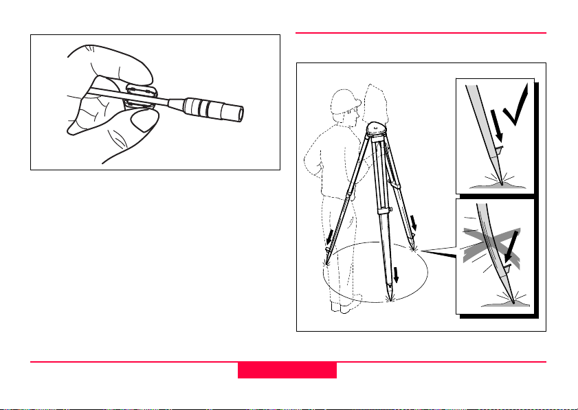
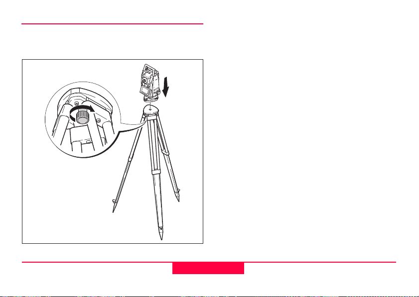
Setting up the tripod
TC400Z18
TPS400-2.1.0en
28
Measuring Preparation /
Page 29
1. Loosen the clamping screws on the tripod legs,
pull out to the required length and tighten the
clamps.
2. In order to guarantee a firm foothold sufficiently
press the tripod legs into the ground. When
pressing the legs into the ground note that the
force must be applied along the legs.
TC400Z19
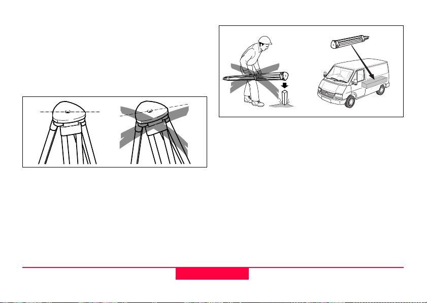
When setting up the tripod pay attention to a
horizontal position of the tripod plate.
Slight corrections of inclination can be made with the
foot screws of the tribrach. Larger corrections must
be done with the tripod legs.
When using a tribrach with an optical
plummet, the laser plummet cannot be used.
TC400Z20
Careful handling of tripod
• Check all screws and bolts for correct fit.
• During transport always use the cover supplied.
• Use the tripod only for surveying tasks.
Measuring Preparation /
29
TPS400-2.1.0en
Page 30
Centring with laser plummet, coarse level-up
1. Place the product onto the tripod head. Tighten
central fixing screw of tripod slightly.
2. Turn footscrews of tribrach into its centre position.
3. Switch on the laser plummet with [FNC] >
[Level/Plummet]. The electronic bubble is
displayed.
4. Position tripod legs so that the laser beam is
aimed to the ground point.
5. Firmly press in tripod legs.
6. Turn the footscrews of the tribrach to centre the
laser beam exactly over the ground point.
7. Move the tripod legs to centre the circular level.
The product is now roughly levelled-up.
TC400Z21
TPS400-2.1.0en
30
Measuring Preparation /
Page 31

Fine tuning in the horizontal with the electronic bubble
1. Switch on the electronic bubble with [FNC] >
[Level/Plummet]. In case of insuffient levellingup an inclined level symbol appears.
2. Center the electronic bubble by turning the foot
screws.
When the electrical bubble is centered, the product
is leveled.
Measuring Preparation /
TC400Z22
3. Check centring with the laser plummet and recentre if necessary.
4. Switch off the electronic bubble and the laser
plummet by pressing [OK] .
31
TPS400-2.1.0en
TC400Z23
Page 32

Laser intensity
Changing the laser intensity
External influences and the surface conditions may
require the adjustment of the intensity of the laser.
The laser can be adjusted in 25% steps as required.
Hints for positioning
TPS400-2.1.0en
TC400Z24
Positioning over pipes or depressions
Under some circumstances the laser spot is not
visible (e.g. over pipes). In this case, the laser spot
can be made visible by using a transparent plate so
the the laser spot can be easily aligned to the centre
of the pipe.
32
Measuring Preparation /
TC400Z25
Page 33

Input mode - method 1
-
-
PtId:
*ABC DEFG HIJK LMNO
F1 F2 F3 F4
PtId:
F1 1234 5678 90. + -
F2 *ABC DEFG HIJK LMNO
F3 PQRS TUVW XYZ_.$ !
F4 &?#@ %*/
-
In entry mode, enter text or numeric values.
Input mode - method 2
In entry mode, enter text or numeric values.
[INPUT] 1. Delete entry, display numeric/ alpha-
numeric softkey bar. The cursor indicates that the product is ready for
input.
2. Selection of range of characters/
range of numbers.
[>>>] Additional characters/ numbers.
3. Select the desired character. Character shifts to the left.
4. Confirm entry.
[ESC] Deletes input and restores previous
value.
Measuring Preparation /
TC400Z26
[INPUT] 1. The full range of available charac-
ters are displayed on the screen.
2. Selection of range of characters/
range of numbers.
Proceed with steps 3 and 4 from method 1.
The method you like to use can be set in the
settings.
33
TPS400-2.1.0en
TC400Z27
Page 34

Edit mode
Info4: PREP
Info4: PROP
-
-
Existing characters are changed in the edit mode.
TC400Z28
1. Start edit mode. Vertical edit bar is
positioned flush right.
Edit bar is positioned flush left.
2. Select range of characters/ range of
numbers.
[>>>] Addional characters / numbers.
3. Overwrite existing characters.
4. Confirm input.
[ESC] Deletes change and restores
previous value.
Erasing characters
1. Place cursor on character to be
deleted.
2. Pressing the navigation key deletes
the relevant character.
3. Confirm input.
[ESC] Deletes the change and restores the
previous value.
TPS400-2.1.0en
34
Measuring Preparation /
Page 35

Inserting characters
-
-
If a character was skipped (e.g. -15 instead of -125)
you can insert it later.
TC400Z29
1. Place cursor on "1".
2. Inserts an empty character on the
right of "1".
3. Select range of characters /range of
numbers.
4. Select relevant character.
5. Confirm input.
Measuring Preparation /
35
TPS400-2.1.0en
Page 36

Numerical and Alphanumerical input
-
Input is made with the softkey bar and the assigned
function keys.
Position the marker in the relevant field.
[INPUT] 1. Calls up the input dialogue.
2. Select range of characters /range of
numbers.
[>>>] Additional characters / numbers.
3. Confirm input.
Selection is limited to valid digits for entries,
that due to their display characteristics, fall into a
certain range (e.g. angles in degrees).
Numerical input
TC400Z30
Alphanumerical input
TC400Z31
TPS400-2.1.0en
36
Measuring Preparation /
Page 37

Character set
Entry mode contains the following characters for
numeric and alphanumeric input.
Numerical Alphanumerical
" + "
" - "
" . "
" 0 - 9 "
(ASCII 43)
(ASCII 45)
(ASCII 46)
(ASCII 48 - 57)
" "
" ! "
" # "
" $ "
" % "
" & "
" ( "
" ) "
" * "
" + "
" , "
" - "
" . "
" / "
" : "
" < "
" = "
" > "
" ? "
" @ "
" A - Z"
" _ "
" ‘ "
(ASCII 32) [space]
(ASCII 33)
(ASCII 35)
(ASCII 36)
(ASCII 37)
(ASCII 38)
(ASCII 40)
(ASCII 41)
(ASCII 42)
(ASCII 43)
(ASCII 44)
(ASCII 45)
(ASCII 46)
(ASCII 47)
(ASCII 58)
(ASCII 60)
(ASCII 61)
(ASCII 62)
(ASCII 63)
(ASCII 64)
(ASCII 65 .. 90)
(ASCII 95)
[Underscore]
(ASCII 96)
The character entry "*" can be used in data fields
where point numbers or codes can be searched for.
Signs
+/- In the alphanumeric character set "+" and "-" are
treated as normal alphanumeric characters with
no mathematical function.
Additional characters
* Place holder during Wildcard point search (see
chapter "Wildcard search").
"+" / "-" appears only in the front position of
an input.
In the edit mode the position of the decimal
place cannot be changed. The decimal place is
skipped.
Measuring Preparation /
37
TPS400-2.1.0en
Page 38

Pointsearch
Pointsearch is a global function used by applications
to e.g. find internally saved measured or fixed
points.
It is possible for the user to limit the point search to
a particular job or to search the whole storage.
The search procedure always finds fixed points
before measured points that fulfill the same search
criteria. If several points meet the search criteria,
then the points are listed according to their age. The
product finds the most current (youngest ) fixed
point first.
Direct search
By entering an actual point number (e.g. "P13") all
points with the corresponding point number are
found.
TC400Z32
TC400Z33
[VIEW] Displays the coordinates of the
selected point.
[ENH] For manual input of coordinates.
[OK] Confirm selected point.
[JOB] To select a different job.
TPS400-2.1.0en
38
Measuring Preparation /
Page 39

Wildcard search
The Wildcard search is indicated by a "*". The
asterisk is a place holder for any following sequence
of characters.
Wildcards are always used if the point number is not
fully known, or if a batch of points is to be searched
for.
TC400Z34
Starts point search.
Examples:
* All points of any length are found.
A All points with exactly the point number "A" are
found.
A* All points of any length starting with "A" are
found (e.g.: A9, A15, ABCD).
*1 All points of any length with a "1" as the second
character are found (e.g.: A1, B12, A1C).
A*1 All points of any length with an "A" as the first
character and a "1" as the third character are
found.
(e.g.: AB1, AA100, AS15).
Measuring Preparation /
39
TPS400-2.1.0en
Page 40

Measuring
-
After switching on and setting up correctly, the total
station is immediately ready for measuring.
In the measurement display it is possible to call up
fixed keys and function keys, as well as trigger keys
and their functions
All shown displays are examples. It is
possible that local software versions are different to
the basic version.
Example of a possible measuring display:
TC400Z35
Calling up the assigned function.
TPS400-2.1.0en
40
Measuring Preparation /
Page 41

FNC Key
Under [FNC] several functions can be called up.
Their applications are described below.
Functions can also be started directly from
the different applications.
Each function from the FNC menu can be
assigned to the [USER]-key (see chapter
"Settings").
Light On /Off
Switches display light on / off.
Level/Plummet
This function enables the electronic bubble and the
range of intensity settings of the laser plummet.
IR/ RL Toggle
Change between the two EDM types IR (Infrared)
and RL (Reflectorless). New setting is displayed for
about one second.
IR: Infrared: Distance measurements with prisms.
RL: Visible laser: Distance measurements without
prisms.
Find more information in chapter "EDM Settings".
Laser Pointer
Switches on or off the visible laser beam for illuminating the target point. The new settings are
displayed for about one second and then saved.
Free-Coding
Select code from the codelist or enter a new code.
Units
Displays the current distance and angle unit and
gives the possibility to change these.
FNC Key
41
TPS400-2.1.0en
Page 42

Target Offset
Measurement Pt.
Offset Pt.
L_Off
set+
T_Off
set
+
T
_Off
set
-
L_Off
set
-
If it is not possible to set up the reflector directly, or
it is not possible to aim the target point directly, the
offset values (length, cross and/or height offset) can
be entered. The values for the angle and distances
are calculated directly for the target point.
H_Offset +: Offset point is higher than measurement
TPS400-2.1.0en
TC400Z36
Procedure:
1. Enter the offset values (length, cross and/or
height) as per the sketch.
2. Define the period for which the offset is to apply.
[RESET]: Sets eccentricity to zero.
3. [SET]: calculates the corrected values and
jumps to the application from which the offset
function was started. The corrected angle and
distances are displayed as soon as a valid
distance measurement has been triggered or
exists.
42
FNC Key
TC400Z37
Page 43

The period of applicability can be set as follows:
Reset after REC
The offset values are reset to 0
after the point is saved.
Height Transfer
Example:
Permanent
The offset values are always reset to 0 when
the application is quit.
The offset values are applied to all
further measurements.
FNC Key
1) Reflector 1
2) Reflector 2
3) Reflector 3
4) Instrument
43
TC400Z38
TPS400-2.1.0en
Page 44

This function determines the height of the product
from measurements to a maximum of 5 target
points, with known heights, in two faces.
With measurements to several targets, the improvement is indicated in the "delta" value.
Procedure:
1. Select known point and input reflector height.
2. After triggering the measurement with [ALL], the
calculated height H
[AddPt] Add another height of a known
point.
[FACE] Measure to the same target in
second face.
3. [SET] Save the changes and set the
station.
is displayed.
0
TPS400-2.1.0en
44
FNC Key
Page 45

Programs
Application pre-settings
These are programs that precede the application
programs and are used to set up and organize data
collection. They are displayed after selecting an
application. The user can select the start programs
individually.
[•] Settings made.
[ ] Settings not made.
TC400Z39
Find further information about individual
start-up programs on the subsequent pages !
Setting job
All data is saved in JOBS, like directories. Jobs
contain measurement data of different types (e.g.
measurements, codes, fixed points, stations,...) and
are individually manageable and can be readout,
edited or deleted separately.
[NEW] Creating a new job.
[SET] Setting the job and back to start-up
this job/directory.
started or if in "Meas & Rec" [ALL] or [REC] was triggered, then the system automatically creates a new
job and names it "DEFAULT".
programs.
All subsequent recorded data is stored in
If no job was defined and an application was
Programs
45
TPS400-2.1.0en
Page 46

Setting Station
Each coordinate computation relates to the currently
set station.
At least plan coordinates (E, N) are required for the
station. The station height can be entered if
required. The coordinates can be entered either
manually or read from the internal memory.
TC400Z40
Known Point
1. Select a ptID stored in internal memory.
2. Input product height.
[OK] Sets the station.
Set manually
1. [ENH] Calls up manual point input
dialogue.
2. Input PtID and coordinates.
3. [SAVE] Saves station coordinates.
Continues to the input of the
product height.
4. [OK] Sets the station.
If no station was set and no application
started and if in "Meas & Rec " [ALL] or [REC] was
activated, then the last station is set as the current
station.
TPS400-2.1.0en
46
Programs
Page 47

Orientation
With the orientation, Hz-direction can be input
manually or points with known coordinates can be
set.
Method 1: Manual input
1. To input a random Hz-orientation.
2. Input of Hz-direction, reflector height and PtID.
3. [ALL] Triggers measurement and sets
orientation.
[REC] Records Hz-direction and sets
orientation.
Method 2: with coordinates
To determine the orientation, a target with known
coordinates can also be used.
1. As orientation with coordinates.
2. Input of the orientation point number and to
determine the point found.
3. To input and confirm the reflector height.
For determining the orientation a maximum of 5
target points with known coordinates can be used.
Programs
1) 1. Target point
2) 2. Target point
3) 3. Target point
47
TC400Z41
TPS400-2.1.0en
Page 48

Orientation coordinates can be either obtained from
the internal memory or entered manually.
The workflow is similar to Free Station workflow.
After each measurement you are asked wether to
proceed or not. Answering with yes brings you back
to the Measurement dialog, to take an additional
measurement. Answering with no brings you to the
Result dialog.
[COMPUTE] Calculates and displays the orienta-
tion results.
[NextPt] Input another backsight point.
1/I Status indication; shows that first point was
measured in telescope position I.
1/I II First point measured in telescope pos. I and
II.
Hz: After the first measurement the finding of
other target points (or the same point when
changing the telescope position) is easier
by setting the indicated angle difference
near to 0°00'00" by turning the product.
: Difference between horizontal distance to
target point computed from coordinates and
the measured distance.
Display of computed orientation
TC400Z42
[OK] Set computed Hz-orientation.
If more than one target point is measured then the
orientation is computed using the "least squares
method".
TPS400-2.1.0en
48
Programs
Page 49

Displaying residuals
[RESID] Display of residuals.
TC400Z43
TC400Z44
1) Actual
2) Design
H: Height correction
: correction of the horizontal distance
Hz: Correction of Hz-angle.
Programs
49
TPS400-2.1.0en
Page 50

Useful information
• If the orientation is only measured in telescope
position II the Hz-orientation is based on telesope position II. If measured only in telescope
position I or mixed the Hz-orientation is based
on telescope position I.
• The prism height may not be changed during
measurements in the first and second telescope
position.
• If a target point is measured several times in the
same telescope position the last valid measurement is used for the computation.
If no orientation was set and an application
was started resp. if in "Meas & Rec" [ALL] or [REC]
was triggered, then the current Hz-direction and Vangle are set as orientation.
TPS400-2.1.0en
50
Programs
Page 51

Applications
-
Introduction
Applications are predefined programs, that cover a
wide spectrum of surveying duties and facilitate
daily work in the field.
The following applications are available:
• Surveying
• Setting Out
• Tie Distance
• Area (plan)
• Free Station
• Reference Line
• Remote Height
• Construction
[MENU] 1. Press the [MENU] fixed key.
2. Selecting the "Program" option.
3. Calling up applications and activating start programs.
[PAGE] Scroll to next page.
Surveying
With the program Surveying the measurement of an
unlimited number of points is supported. It is comparable to "Meas & Rec", but includes stationing, orientation and coding.
TC400Z45
Procedure:
1. Input PtID, codes and the reflector height if
desired.
2. [ALL] Triggers and records measure-
ments.
[IndivPt] Switches between individual and
current point number.
Programs
51
TPS400-2.1.0en
Page 52

Two coding methods are available:
1. Simple coding:
Input a code into the relevant box. The code is
stored along with the corresponding measurement.
2. Expanded coding:
Press the [CODE] softkey. The code that was
input is searched for within the code list and it is
possible to add attributes to the code.
Stake out
This program calculates the required elements to
stakeout points from coordinates or manualy
entered angles, horizontal distances and heights.
Setting out differences can be displayed continuously.
Setting out coordinates from memory
Procedure:
Select the point.
[DIST] Starts measurement and calculation of
the stake-out elements.
[REC] Saves the displayed values.
[B&D] Input direction and Hz-distance of stake
out point.
[MANUAL] Enables simplified input of a point
without ptID and without the possibility
of storing the data of the point.
TPS400-2.1.0en
52
Programs
Page 53

Polar Stake out
Normal indication of polar stake out offsets Hz,
, .
TC400Z46
1) Actual
2) Point to be stake out
Hz: Angle offset: positive if point to be set-
out is to the right of the actual direction.
: Longitudinal offset: positive if point to be
stake out is further away.
: Height offset: positive if point to be
stake out is higher than measured point.
Orthogonal Stake out
The position offset between measured point and
stake out point is indicated in a longitudinal and
transversal element.
TC400Z47
1) Actual
2) Point to be stake out
L: Longitudinal offset: positive if nominal
point further away.
T: Transversal offset, perpendicular to
line-of-sight: positive if nominal point is
to the right of measured point.
Programs
53
TPS400-2.1.0en
Page 54

Cartesian Stake out
Setting out is based on a coordinate system and the
offset is divided into a north and east element.
TC400Z48
1) Actual
2) Point to be stake out
E Easting offset between stake out and actual
point.
N Northing offset between stake out and
actual point.
TPS400-2.1.0en
54
Programs
Page 55

Free Station
The application "Free Station" is used to determine
the product position from measurements to a
minimum of two known points and a maximum of
five known points.
TC400Z49
The following measurements sequences to
target points are possible:
1. Hz- and V-angles only (resection)
2. Distance and Hz- and V-angle (3 point
resection)
3. Hz- and V-angles to some point(s) and Hz- and
V-angle plus distance to other point(s).
The final computed results are Easting, Northing
and Height of the present product station, including
the products Hz-circle orientation.
Standard deviations and residuals for accuracy
assessments are provided.
Programs
55
TPS400-2.1.0en
Page 56

Measuring facilities
Single face I or II or dual face I + II measurements
are always possible. No specific point sequence or
specific face sequences are required.
Gross errors checks are made for dual face
measurements to ensure the same point(s) are
sighted with the other face.
If a target point is measured several times in
the same telescope position the last valid measurement is used for computation.
Measurement restrictions:
• 2 face measurements
When measuring the same target in both faces,
the reflector height may not be altered when
changing the telescope position.
• Target points with 0.000 height
Target points with 0.000 height are discarded for
height processing. If target points have a valid
height of 0.000 m, use 0.001 m to enable it for
height processing.
Computation procedure
The measuring procedure automatically determines
the mothod of evaluation, e.g. resection, 3 point
resection, etc.
If more than the minimum required measurements
are performed, the processing routine uses a least
squares adjustment to determine the plan position
and averages orientation and heights.
1. The original averaged face I and face II
measurements enter the computation process.
2. All measurements are treated with the same
accuracy, whether these are measured in single
or dual face.
3. Easting and northing is determined by the
method of least squares, including standard
deviation and improvements for Hz-direction
and horizontal distances.
4. The final height (H) is computed from averaged
height differences based on the original
measurements.
5. The Hz-circle orientation is computed with the
original averaged face I and face II measurements and the final computed plan position.
TPS400-2.1.0en
56
Programs
Page 57

Procedure:
Programs
TC400Z50
Enables you to define an accuracy limit.
TC400Z51
Here you can enter a limit for the standard deviation
values. If your computed deviation exceeds the limit
a warning dialog appears, where you can decide
wether to proceed or not.
1. Input of the name of the station and the height of
the product.
2. Input of the target ptID and the reflector height.
[ALL] Triggers angle and distance
measurement (3 point resection).
[REC] Saves Hz-direction and V-angle
(resection).
57
TPS400-2.1.0en
TC400Z52
Page 58

[AddPt] Input another backsight point.
[COMPUTE] Calculates and displays the station
coordinates, if at least 2 points and
a distance were measured.
3/I Indicates that the third point in tele-
scope position I was measured.
3/I II Indicates that the third point in tele-
scope positions I and II.
Results
Displays calculated station coordinates:
TC400Z53
[AddPt] Switches to measurement display,
to measure additional points.
[RESID] Displays residuals.
[STDEV] Displays standard deviation.
[SET] Sets the displayed coordinates and
product height as new station.
TPS400-2.1.0en
58
Programs
Page 59

If the product height was set to 0.000 in the
setup screen, then the station height refers to height
of trunnion axis.
Displays standard deviations:
TC400Z54
S.Dev E0, N0, H0 Standard deviation of the
S.Dev Ang Standard deviation of the orien-
station coordinates
tation
This dialog shows the computed residuals:
Residual = Calculated value - Measured value
TC400Z55
With the function keys, scroll
between the residuals of the indi-
vidual backsight points.
Programs
59
TPS400-2.1.0en
Page 60

Warnings / Messages
Important messages Meaning
Selected point has no valid data !
Max 5 points supported !
Invalid data - no position computed !
Invalid data - no height computed !
Insufficient space in job ! The present selected job is full and does not allow further storage.
Hz (I - II) > 0.9 deg, measure point again !
V (I - II) > 0.9 deg, measure point again !
More points or distance required !
TPS400-2.1.0en
This message occurs if the selected target point has no easting or northing
coordinate.
If 5 points have already been measured and another point is selected. The
system supports a maximum of 5 points.
The measurements may not allow final station coordinates (Eastings, Northings) to be computed.
Either the target height are invalid or insufficient measurements are available
to compute a final station height.
This error occurs if a point was measured in one face and the measurement
in the other face differs by more than 180° ±0.9° for the horizontal angle.
This error occurs if a point was measured in one face and the measurement in
the other face differs by more than 360° - V ±0.9° for the vertical angle.
There is insufficient data measured to be able to compute a position. Either
there are not enough points used or not enough distances measured.
60
Programs
Page 61

Reference Line
This program facilitates the easy setting out or
checking of lines for buildings, straight sections of
road, simple excavations, etc.
A reference line can be defined by referencing a
known base line. The reference line can be offset
either longitudinally or in parallel to the base line, or
be rotated around the first base point as required.
Definition of the Base line
The base line is fixed by two base points
that can be defined in three ways:
• Measured points
• Enter co-ordinates using keypad
• Select point from memory.
Definition of the base points
Procedure:
1. Measuring base points:
Input ptID and measure base points with [ALL]
or [DIST] / [REC].
2. Base points with coordinates:
[FIND] Starts to search for the ptID
entered.
[ENH] Manually input coordinates.
[LIST] Displays the list of available points.
Analogue procedure for the second base point.
TC400Z561
1) 1st base point
2) 2nd base point
3) Base line
4) Reference line
Programs
61
TPS400-2.1.0en
Page 62

Base line
1st base point
2nd base
point
Reference point
Base
line
Re
feren
c
e
l
ine
Offs+
Line+
Rot
+
The base line can be offset longitudinally and
parallel, or rotated. This new line is called the reference line. All measured data refers to the reference
line.
TPS400-2.1.0en
TC400Z57
Input of the parameters:
Use the navigation keys to select the
shifting and rotation parameters of the reference line.
The following entries are possible:
Offset+: Parallel offset of the reference line
to the right, referred to the direction
of the base line (1-2).
Line+: Longitudinal offset of the start point
(=reference point) of the reference
line in the direction of base point 2.
62
Programs
TC400Z58
Page 63

Rotate+: Rotation of the reference line clock-
1st reference point
measured point
Refere
nce
l
ine
p
L
ine+
p
O
ffset
+
wise around the reference point.
H-Offset+: Height offset; the reference line is
higher than the first base point.
Meaning of the softkeys:
[NewBL] Return to the definition of a new
base line.
[StOut] Opens the "Orthogonal Stake out"
application.
[L&O] Opens the "Reference Line" appli-
cation.
[SHIFT=0] Sets offset / rotation to zero.
Reference Line
Programs
TC400Z59
The [L&O] function calculates from measurements
or coordinates longitudinal, cross and height differences of the target point relative to the reference
line.
63
TPS400-2.1.0en
Page 64

The height of the first reference point is always used
pHeight+
pHeight-
1st base point
1st reference point
Reference height
Height diff.+
as the reference height for the calculation of height
differences (
).
TC400Z60
TC400Z61
If tracking mode is activated (see "EDM
Settings section"), correction values for the position
of the reflector are displayed continuously.
TPS400-2.1.0en
64
Programs
Page 65

Orthogonal Stake out
1st reference point
setting out point
measured
point
Reference l
ine
pO
ff
set
-
p
L
ine
-
You can enter longitudinal, transverse and height
offsets for the target points to be set-out relative to
the reference line. The program calculates the difference between a measured point and the calculated
point. The program displays the orthogonal (
Offset, ) and the polar (Hz, , )
differences.
Procedure:
1. Input the orthogonal stake out elements or call
up of a point from internal memory.
2. [SET] Confirm entry and start calculation.
Line,
Example "orthogonal methods"
TC400Z62
Programs
65
TPS400-2.1.0en
Page 66

Display in measure mode:
TC400Z63
+Hz Turn telescope clockwise to the setting
out point.
The setting out point is further away
+
than the point measured.
The setting out point is higher than the
+
measured point.
The signs for the distance and angle differences are
TC400Z64
exactly the same as for the "Stake out" application.
These are correction values (required minus actual).
TPS400-2.1.0en
66
Programs
Page 67

Warnings / Messages
Important
Messages
Save via RS232 !
Base line too short !
Co-ordinates invalid !
Programs
Meaning
Data output (system setting
menu) via RS232 interface is
activated. To be able to succesfully start reference line, the
"INTERN" setting must be
enabled.
Base line is shorter than 1 cm.
Choose base points such that
the horizontal separation of both
points is at least 1 cm.
No co-ordinates or invalid coordinates for a point. Ensure that
a point used has at least one
Easting and one Northing coordinate.
67
TPS400-2.1.0en
Page 68

Tie Distance
Centre point
Slope distance 1-2
Slope distance 1-3
Slope distance 1-4
The application Tie Distance computes slope
distance, horizontal distance, height difference and
azimuth of two target points measured online,
selected from the Memory or entered using the
Keypad.
The user can choose between two different
methods:
Polygonal (A-B, B-C)
Radial (A-B, A-C)
Polygonal Method:
TC400Z65
TPS400-2.1.0en
Radial Method:
In principal both methods are the same.
Any differences will be described.
Procedure:
1. Determine first target point.
[ALL] Starts measurement to the target
point.
[FIND] Searches internal memory for point
entered.
2. Determine second target point.
Proceed as with first target point.
68
TC400Z66
Programs
Page 69

3. Result is displayed.
Brg Azimuth between point1 and point2.
Slope distance between point1 and
point2.
Horizontal distance between point1
and point2.
Height difference between point1
and point2.
Grade Grade [%] between point1 and
point2.
Softkeys - polygonal method:
[NewPt 1] An additional missing line is
computed. Program starts again (at
point 1).
[NewPt 2] Point 2 is set as starting point of a
new missing line. New point (Pt 2)
must be measured.
[RADIAL] Switches to radial method.
Softkeys - radial method:
[NewPt 1] Determine new central point.
[NewPt 2] Determine new radial point.
[POLY] Switch to polygonal method.
Programs
69
TPS400-2.1.0en
Page 70
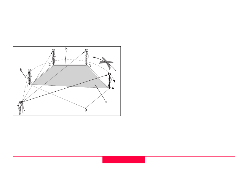
Area (plan)
The application areas (plane) computes online
areas from an unlimited number of points connected
by straights. The points can be measured, selected
from memory or input with the keyboard.
Procedure:
1. Determine the first area point
[ALL] Starts the measurement to the
point.
[FIND] Searches internal memory for point
entered.
[XYZ] For manual input of the coordinates.
2. Determine additional area points
Proceed as with first area point.
[RESULT] Displays additional results (Circum-
ference).
The area is calculated and displayed once
three points have been measured or selected.
a) Start
b) Polygonal length, from starting point to the
actual measured point.
c) Actual area, always closed to the starting
point (1).
TPS400-2.1.0en
TC400Z67
70
Programs
Page 71

Remote Height
Points directly above the base prism can be determined without a prism at the target point.
TC400Z68
1) Remote point
2) Height diff.
3) Slope distance
4) Base point
Procedure:
1. Input ptID and reflector height
[ALL] Starts measurement to base point
and continues to 2.
[hr?] Starts the program that determines
an unknown reflector height.
1.1 [ALL] Starts measurement to base point.
1.2 Aim at top of reflector and confirm
with [Set_V].
2. Aim at inaccessible height point
[SAVE] Saves the measured data.
[BasePt] Input and measurement of a new
base point.
Programs
71
TPS400-2.1.0en
Page 72

Construction
PtID :
A11
hr : 1.500 m
: 7.225 m
Off: 10.194 m
: -1.673 m
This application allows to define a construction site
by combining set-up of the product along a construction line, measuring and setting out points in relation
to the line.
After selecting the application you have two
options:
a) Defining a new construction site
or
b) Continue with previous site (skips set-up)
Procedure:
Defining new site:
1. Measure line Start point [ALL], [DIST]+[REC]
2. Measure second line point [ALL], [DIST]+[REC]
In case, you have entered coordinates by
ENH and measured to known points a plausibility
check informs you about the calculated line length,
the actual length and the difference.
As built check:
This dialog shows you the
Height of a measured point in relation to the line.
Line, Offset and
TPS400-2.1.0en
[ShiftLn] Allows you to enter values for
shifting the line.
[LAYOUT] Switches to Layout-mode.
Line is positive:
Measured point is in direction from line start - to line
end point.
Offset is positive:
Measured point is right of line.
Height is positive:
72
Programs
TC400Z69
Page 73

Measured point height is above line start point’s
height.
The height of the line start point is always
used as the reference height!
Layout
Here you can search or enter points for staking out
related to the measured line.
TC400Z70
[ShiftLn] Allows you to enter values for
shifting the line.
[AsBUILT] Switches to AsBuilt-mode.
The graphics show you the position of the prism
related to the stake out point. Below, the exact
values are displayed, combined with arrows to show
the direction.
Line is positive (arrow up):
Target point is further away than the measured
point.
Offset is positive (arrow right):
Target point is right of the measured point.
Height is positive (arrow up):
Target point is higher than the measured point.
The height of the line start point is always
used as the reference height!
The graphics are scaled to give a better
overview. Therefore it’s possible that the station
point moves in the graphics.
Be aware that the line start point and the line
end point are measured in the previous coordinate
system. When staking out this points they appear in
the old system and appear as shifted.
Programs
73
TPS400-2.1.0en
Page 74

During use of the application the previous
Orientation and Station parameters will be replaced
by the new calculated ones.
Coding
Codes contain information about recorded points.
With the help of coding, points can be assigned to a
particular group simplifying later processing.
More information on coding can be found under
"Data management".
GSI-coding
Code: Code name
Desc.: Additional remark
Info1: more, freely editable
... information
Info8: lines
Procedure:
1. Move cursor to field "Code".
2. Input code.
3. [ALL] Starts the distance measurement
and saves the values including the
entered code.
[CODE] Searches for the entered code and
offers the option of adding
attributes.
TC400Z71
[SET] Sets the code block.
[AddList] Adds an entered code into codelist.
[RECORD] Closes the code entry or code selection
and saves the code block.
TPS400-2.1.0en
74
Programs
Page 75

Manual code input
Individual code blocks can be entered directly via
keypad.
TC400Z72
1. [INPUT] Enter desired code.
2. Confirm with ENTER.
3. Enter the attributes 1-4.
4. [SET] Sets the code block.
Extending / editing code
1. Call available code from code list.
2. Attributes can be overwritten freely.
Exceptions:
With the codelist editor of LGO/LGO-Tools a status
can be assigned to the attributes.
• Attributes with "fixed status" (see LGO/LGOTools) are write-protected. They cannot be overwritten or edited.
• For attributes with status "Mandatory" an input
or a confirmation is required.
• Attributes with status "Normal" can be edited
freely.
Recording code block
[SET] Sets the code block temporarily in the system
after ending the code functions. Recording only with
measurement and always with reference to the
actual point number.
Programs
75
TPS400-2.1.0en
Page 76

Warnings / Messages
Important
Messages
Attrib. cannot be
changed !
No codelist available !
Entry required ! Code missing. Extend input.
Individually entered code blocks are not
added to the code list.
Leica Geo Office Tools (LGO-Tools)
Codelists can be easily created and uploaded to the
product using the supplied "LGO-Tools" Software.
TPS400-2.1.0en
Attribute with fixed status cannot
be changed.
No codelist in memory. Manual
input for code and attributes are
called automatically.
Meaning
76
Programs
Page 77

Settings
This menu enables extensive user-specific settings
in order to adapt the product to their own requirements.
Contrast
Setting the display contrast in 10% steps.
Trigger key
Configuration of the trigger key on side cover.
Off Trigger key deactivated.
ALL Trigger key with same function as
the [ALL]-key.
DIST Trigger key with same function as
the [DIST]-key.
USER Key
Configure the USER Key with a function from the
FNC-menu.
V-Setting
The "0"- orientation of the vertical circle can be
either selected for the zenith, the horizontal plane or
in %.
• Zenith: Zenith=0°; Horizon=90°
• Horizon: Zenith=90°; Horizon=0°
• V-(%): 45°=100%; Horizon=0°
The % value increases rapidly. "--.--%"
appears on the display above 300%".
Tilt Correction
Off Tilting compensation switched off.
1-axis V-angles relate to the plumb line.
2-axis V-angle refer to the plummet line and
If the product is used on an unstable base (e.g.
shaking platform, ship, etc.) the compensator should
be switched off.
This avoids the compensator drifting out of it's
measuring range and interupting the measuring
process by indicating an error.
even after the product is switched off.
the Hz-directions are corrected by the
standing axis tilt.
The compensator setting remains active
Settings
77
TPS400-2.1.0en
Page 78

Sector Beep
Off Sector Beep switched off
On Sector Beep sounds at right angles (0°,
90°, 180°, 270° or 0, 100, 200, 300 gon)
Example Sector Beep:
From 95.0 to 99.5 gon (or from 105.0 to 100.5 gon)
a "Fast beep" sounds whilest from 99.5 to 99.995
gon (or from 100.5 to 100.005 gon) a "Permanent
beep" sounds.
TPS400-2.1.0en
1) No beep
2) Fast beep (interrupted)
3) Permanent beep
78
TC400Z73
Settings
Page 79

Beep
The beep is an acoustic signal after each key stroke.
Off Beep switched off
Normal Normal volume
Loud Increased volume
Hz Incrementation
Right Set right Hz for "Clockwise direction
measurement".
Left Set left Hz for "Counter-clockwise direc-
tion measurement". "Counter-clock-
wise" directions are only displayed but
saved as "Clockwise direction".
Reticle Illumination
The reticle illumination is only switched on if the
display illumination is on.
Low Low illuminaton
Medium Medium illuminaton
High High illuminaton
DSP Heater
On Is automatically activated when the
Data Output
RS232 Data is recorded via the serial interface.
Intern All data is recorded in the internal
GSI 8/16
Select GSI output format.
GSI 8: 81..00+12345678
GSI 16: 81..00+1234567890123456
Mask 1/2
Select GSI output mask.
Mask 1: PtID, Hz, V, SD, ppm+mm, hr, hi
Mask 2: PtID, Hz, V, SD, E, N, H, hr
display illumination is on and the product
temperature is
For this purpose, a data storage device
must be connected.
memory.
5°C.
≤
Settings
79
TPS400-2.1.0en
Page 80

Hz Collimation
On Hz Collimation is switched ON.
Off Hz Collimation is switched OFF.
If option "Hz Collimation ON" is active, each
measured Hz-angle is corrected (depending on
V-angle).
For normal operation the Hz-collimation remains
switched on.
More information on Hz-collimation can be
found under "Adjusments".
Auto-OFF
Enable The product is switched off after 20
Disable The product is switched on perma-
Sleep Economy mode. product is recovered
minutes without any action (= no key
pressed; V and Hz angle deviation
±3' / ±600cc).
≤
nently. Battery discharges quicker.
by any key stroke.
Min. Reading
The displayed angle format can be selected in three
steps.
• For 360°'":
0° 00' 01" / 0° 00' 05" / 0° 00' 10"
Always " are indicated.
• For 360°:
0.0005° / 0.001° / 0.005°
• For gon:
0.0005 gon / 0.001 gon / 0.005 gon
• For mil:
0.01 mil / 0.05 mil / 0.10 mil
Input method
Here you can select the method to input alphanumeric characters.
• Method 1
Standard method
• Method 2
Advanced method
TPS400-2.1.0en
80
Settings
Page 81

Angle Unit
° ' " (degree sexagesimal)
possible angle values:
0° to 359°59'59''
DD (degree decimal)
possible angle values:
0° to 359.999°
gon possible angle values:
0 gon to 399.999 gon
mil possible angle values:
0 to 6399.99mil
The setting of the angle units can be changed at any
time.
The actual displayed values are converted
according to the selected unit.
Distance Unit
meter Meter
ft-in1/8 US-feet-Inch-1/8 inch
US-ft US-feet
INT-ft International feet
Temperature
°C Degree Celsius
°F Degree Fahrenheit
Pressure
mbar Millibar
hPa Hecto Pascal
mmHg Millimeter mercury column
inHg Inch mercury column
Settings
81
TPS400-2.1.0en
Page 82

EDM Settings
The EDM-settings contain a detailed menu with
selection boxes.
TC400Z74
EDM Mode
With TCR products different settings for measurements with visible (RL) and invisible (IR) EDM type
are available.
Depending on selected measuring mode the selection prism types are different.
Fine measuring mode for high
IR-Fine
IR-Fast
IR-Track
IR-Tape
precision measurements with
prisms
(2mm + 2 ppm)
Quick measuring mode with
higher measuring speed and
reduced accuracy
(5mm + 2 ppm)
Continuous distance
measuring
(5mm + 2 ppm)
Distance measurement using
Retro targets
(5mm + 2 ppm)
TPS400-2.1.0en
82
EDM Settings
Page 83

RL-Short
RL-Track
RL-Prism
Short range. For distance
measurements without prisms
with a target distance up to 80 m
(3mm + 2 ppm)
Continuous distance measurement without prisms
(5mm + 2 ppm)
Long range. For distance
measurements with prisms
(5mm + 2 ppm)
360° prism
GRZ4
360° Mini
prism
GRZ101
+23.1
+30.0
With the RL-EDM each object in the beam is
measured (possibly also branches, cars, etc.).
Prism type
Calling the function in the EDM settings.
Leica
Prisms
Standard
prism
GPH1 +
GPR1
Constants
[mm]
0.0
EDM Settings
Miniprism
GMP101/102
JPMINI
Reflective
targets
USER
RL
83
+17.5
+34.4
Mini prism
+34.4
is set at "Prismconst"
--
(-mm + 34.4; e.g.: mm = 14 ->
input = -14 + 34.4 = 20.4)
+34.4
Reflectorless
TPS400-2.1.0en
Page 84

Prism Constant
Calling the function in the EDM settings.
Entry of a user specific prism constant. Input can
only be made in [mm].
Limit value: -999 mm to +999 mm
Laser Pointer
Off: Visible laser beam is switched off.
On: Visible laser beam for visualising the target
point is switched on.
Guide Light
The person at the prism can be guided by the
flashing lights directly to the line of sight. The light
points are visible up to a distance of 150 meters.
This is useful when setting out points.
TC400Z75
1) Flashing red diode
2) Flashing yellow diode
Operat. range: 5 - 150 m (15 -500 ft)
Divergence: 12 m (40 ft) at 100 m (330 ft)
TPS400-2.1.0en
84
EDM Settings
Page 85

[SCALE]
Scale of projection.
TC400Z76
Scale factor:
Entering the scale of projection. Measured values
and coordinates are corrected with the PPM parameter.
[PPM=0] Sets default parameters.
[PPM]
Input of individual scaling parameters.
[P/Temp]
Input of atmospheric parameters.
Atmospheric Parameters (ppm):
Distance measurement is influenced directly by the
atmospheric conditions of the air in which distance
measurement are taken.
TC400Z77
In order to take into consideration these influences
distance measurements are corrected using atmospheric correction parameters.
EDM Settings
85
TPS400-2.1.0en
Page 86

• Ht. a. MSL
Height above sea level at product location.
• Temperature
Air temperature at product location.
• Pressure
Air pressure at product location.
• Atmos PPM:
Calculated and indicated atmospheric PPM.
Signal
[SIGNAL] Displays EDM signal strength (reflection
strength) in steps of 1%. Permits
optimal aiming at distant barely visible
targets.
TPS400-2.1.0en
86
EDM Settings
Page 87

File Management
The File Manager contains all functions for entering,
editing and for checking data in the field.
TC400Z78
TC400Z79
Job
Jobs are a summary of data of different types, e.g.
fixed points, measurements, codes, results, etc.
The job definition consists of the input of job name
and user.
Additionally, the system generates time and date at
the time or creation.
Job search:
Scrolling through jobs.
[DELETE] Deletes selected job.
[SET] Sets the selected job.
[NEW] Starts new job.
File Management
87
TPS400-2.1.0en
Page 88

Fixpoints
Valid fixed points contain at least the ptID and the
coordinates (E, N) or (H).
[DELETE] Deletes selected fixed point.
[FIND] Starts point search. Exact ptIDs can
be entered or the * wildcard-criteria
used.
[NEW] Opens input for ptID and coordi-
nates.
Measurements
Measurement data available in the internal memory
can be searched and displayed or erased.
[FIND] Starts point search dialogue.
[VIEW] Displays all measurements.
Codes
To each code a description and a maximun of 8
attributes with up to 16 characters can be assigned.
TC400Z80
TC400Z81
[SAVE] Save data.
[VIEW] Starts search dialogue.
[ATTRIB] Input of attributes.
TPS400-2.1.0en
88
File Management
Page 89

Initialize Memory
Deletes jobs, single data areas of a job or all
data.
[DELETE] Starts deleting process within the
selected area.
[ALL] Deletes all data in memory. All data
will be lost !
Deleting the memory cannot be undone.
After confirming the message all data is deleted
permanently.
Memory Statistic
Displays job specific memory information such as:
• Number of stored fixpoints.
• Number of recorded data blocks (measured
points, codes, etc.).
• Number of free or not defined jobs.
File Management
89
TPS400-2.1.0en
Page 90

Start-up sequence
Sets the screen the product starts in when switched
on. E.g. the electronic bubble can be displayed at
every start.
Procedure:
After confirming the dialogue of notification, the
"Meas & Rec" screen is displayed. A maximum of 16
of the next key presses are stored. The sequence is
ended with [ESC]. If the start sequence is activated,
the stored key presses are executed automatically
when the product is switched on.
The automatic start sequence has the same
effect as pressing the keys manually. Certain
product settings can not be made in this way. "Relative entries" such as automatically setting "IR-FINE"
upon switching on the product, are not possible.
[OK] Stores current settings.
TC400Z82
[RECORD] Defines the key presses that are
executed automatically upon start up.
[Play] Starts to run the recorded sequence.
TPS400-2.1.0en
90
Start-up sequence
Page 91

Calibrations
Determining Line-of-sight error and V-Index
The calibration contains the determination of the
following product errors:
• Hz-collimation
• V-index (simultaneously electronic level)
For determining the Hz-collimation or the V-index it
is necessary to measure in both telescope positions.
The procedure can be started in any telescope position.
The user is guided clearly through the procedure. A
wrong determination of product error is thus eliminated.
The products are adjusted in the factory prior to
shipping.
product errors can change with time and temperature.
These errors should be determined before
the product is used for the first time, before precision
surveys, after long periods of transport, before and
after long periods of work, and if the temperature
changes by more than 10°C (18°F).
Before determining the product errors,
level-up the product using the electronic
bubble. The product should be secure
and firm, and should be protected from
direct sunlight in order to avoid thermal expansion
on one side only.
Calibrations
91
TPS400-2.1.0en
Page 92

Line-of-sight error (Hz-collimation)
V-Index (Vertical index error)
The line-of-sight error or collimation error (C) is the
TC400Z83
deviation from the perpendicular between the tilting
axis and the line of sight.
The effect of the line-of-sight error to the Hz-angle
increases with the vertical angle.
For horizontal aimings the error of Hz equals the
line-of-sight error.
TPS400-2.1.0en
The vertical circle should read exactly 90° (100 gon)
when the line of sight is horizontal. Any deviation
from this figure is termed vertical index error (i).
By determining the vertical index error the electronic
level is adjusted automatically.
Procedures and conditions required to
correct line-of-sight and height index errors are the
same. Thus the procedure will only be described
once.
92
Calibrations
TC400Z84
Page 93

Hz-collimation
V-index
Display adjustment value:
Summarizes saved values.
Procedure:
1. Level product with electronic bubble.
2. Aim at a point approximately 100m from the
product which is within 5° of the horizontal.
4. Change telescope position and aim to the point
again.
For checking the horiontal aiming Hz and V are
displayed.
3. [ALL]: Trigger measurement.
Calibrations
TC400Z85
5. [ALL]: Starts measurement
6. Displays the old and new calculated values.
[SET] Sets new calibration data.
[ESC] Quits program without setting new
calibration data.
93
TPS400-2.1.0en
TC400Z86
Page 94

Warnings / Messages
Important Messages Meaning Measures
V-Angle not suitable for
calibration (Check V-angle
or face) !
Calibration result out of
tolerance. Previous values
retained !
Hz-Angle out of limit !
Measurement Error. Try
again.
Aiming tolerance not met or telescope position/face not changed.
Computed values out of tolerance.
Previous values retained.
Hz-angle in second face/telescope pos.
deviates more than 5 gon from the target
point.
Measurement error appeared (e.g. instable
set up or period between measuring in telescope position I and II too long).
Aim on the target point with an accuracy of
min. 5 gon. The target point must be
approximately in the horizontal plane.
Confirmation of the message required.
Repeat measurements.
Confirmation of the message required.
Aim on the target point with an accuracy of
min. 5 gon.
Confirmation of the message required.
Repeat the process.
Confirmation of the message required.
TPS400-2.1.0en
94
Calibrations
Page 95

COMM Parameters
For data transfer between PC and product the
communication parameters of the serial interface
RS232 must be set.
Leica Standard setting
19200 Baud, 8 Databit, No Parity, 1 Stopbit, CR/LF
Baudrate
Data transfer speed 2400, 4800, 9600, 19200
[bits / second]
Databits
7 Data transfer is realized with 7 databits. Is set
automatically if parity is "Even" or "Odd".
8 Data transfer is realized with 8 databits. Is set
automatically if parity is "None".
Parity
Even Even parity
Odd Odd parity
None No parity (if data bit is set to 8)
Endmark
CRLF Carriage return; line feed
CR Carriage return
Stopbits
Fixed setting 1.
Interface plug connections:
TC400Z87
1) External battery
2) Not connected / inactive
3) GND
4) Data reception (TH_RXD)
5) Data transfer (TH_TXD)
TH ... Theodolite
COMM Parameters
95
TPS400-2.1.0en
Page 96

Data Transfer
With this special function measured data can be transfered via the serial interface to a receiver (e.g. a
Laptop). Using this type of transfer the success of the
transfer is not checked.
Job: Selection of job from which data should
be transfered.
Data: Select the data range to be transferred
(measurements, fixed points)
Format: Select output format. Select Leica-GSI-
format, or your own format created in
the "Format Manager" and transfer to
the LGO/LGO-Tools.
[SEND] Starts the transmission.
Example:
Within the "data" setting "MEASUREMENTS" a data
set could be shown as follows:
11....+00000D19 21..022+16641826
22..022+09635023 31..00+00006649
58..16+00000344 81..00+00003342
82..00-00005736 83..00+00000091
87..10+00001700
If the receiver is to slow in processing data
the data could be lost. With this type of data transfer
the product is not informed about the performance of
the receiver (no protocol).
GSI-ID’s
11 PtID
21 Horizontal direction
22 Vertical angle
31 Slope distance
32 Horizontal distance
33 Height difference
41-49 Codes and attributes
51 ppm [mm]
58 Prism constants
81-83 (E, N, H) Target point
84-86 (E, N, H) Stand point
87 Reflector height
88 product height
TPS400-2.1.0en
96
Data Transfer
Page 97

System Info
Displays helpful information and date / time are set.
• Battery
Remaining battery power (e.g. 40%).
• Instr.Temp.
Measured product temperature.
•Date
Displays the current date.
•Time
Displays current time.
[DATE] Change date and format.
Format: There are three display formats:
• DD.MM.YYYY
• MM.DD.YYYY
• YYYY.MM.DDT
Date: Input date
[TIME] Set time.
[SW-Info] The software of the product is
composed of different software packages. Depending on the package,
different versions are possible.
Op-System: Operating System
App.-SW: Applications, functions
and menu
Layout: User displays
System Info
97
TPS400-2.1.0en
Page 98

Care and Storage
Transport
When transporting or shipping the equipment
always use the original Leica Geosystems packaging (transport case and shipping cardboard).
After a longer period of storage or transport
of your product always check the field ajustment
parameters indicated in this manual before using the
product.
TPS400-2.1.0en
In the field
When transporting the equipment in the field,
always make sure to
• either carry the product in its original transport
case or,
• carry the tripod with its legs splayed across your
shoulder, keeping the attached product upright.
98
Care and Storage
TC400Z88
Page 99

Inside vehicle
Never transport the product loose inside the
vehicle.
The product can be damaged by blows and vibrations. It must always be transported in its case and
be properly secured.
Shipping
For shipping the product by rail, aircraft or ship use
the Leica Geosystems original packaging (transport
case or shipping cardboard) or another suitable
packaging securing the product against blows and
vibrations.
Storage
TC400Z89
When storing the equipment, particularly in
summer and inside a vehicle, take the temperature
limits into account.
When storing the intrument inside a building also
use the transport case (if possible, in a safe place).
Care and Storage
99
TPS400-2.1.0en
Page 100

TC400Z90
If the product becomes wet, leave it
unpacked. Wipe down, clean, and dry the product
(at not more than 40 °C/ 104°F), transport case,
foam inserts, and accessories. Pack up the equipment only when it is perfectly dry.
When using the product in the field always close the
transport case.
Batteries
• The permissible temperature range for storing is
-40°C to +55°C / -40°F to +131°F. A storage
temperature range of 0°C to +20°C / +32°F to
68°F in dry environment is recommended to
minimize self-discharging of the battery.
• At the recommended storage temperature
range, batteries containing a 10% to 50%
charge can be stored for up to one year. After
this storage period the batteries must be
recharged.
• Remove batteries from the product and the
charger before storing.
• After storage recharge batteries (NiMH) before
using.
• Protect batteries from damp and wetness. Wet
or damp batteries must be dried before storing
or use.
TPS400-2.1.0en
100
Care and Storage
 Loading...