

Page 1

LEICA SF 60
INSTRUCTION MANUAL
Page 2
EN
1b
1a
1
1c
2
4
5
10
9
3
8a
11
8
11e
7
11a
11c
11b
11d
6a
6
6b
1
13
12
14
2
Page 3

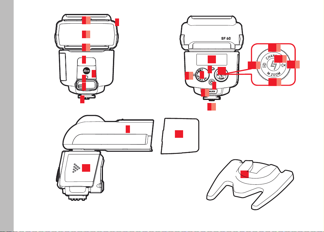
PART DESIGNATIONS
1 Reflector head, with
a diffuser
b bounce card
c wide-angle diffuser
2 Video light
3 Sensor for cordless off-camera operation (behind infrared-per-
meable panel)
4 AF assist light
5 Input jack for connecting external battery pack (behind cover)
6 Mounting foot with
a unlock button
b locking pin
7 Power switch
8 Mode dial and
a index
9 Ready LED / test flash button
10 LCD panel
11 Combination dial / rocker switch with settings for
a channel selection
b audible signal
c device pairing
d zoom mode / focal length
e button lock
12 Battery compartment cover
13 Clip-on softbox
14 Off-camera stand with ¼“ thread
EN
3
Page 4
EN
FOREWORD
SIGNIFICANCE OF THE ADVISORY CATEGORIES
Dear Customer,
Thank you for purchasing the Leica SF60 system flash unit, and
congratulations on choosing the best system flash solution for your
Leica camera. We wish you every enjoyment and success with your
new flash unit.
To get the most out of your Leica SF 60, please read this manual
before use.
Note:
Additional information
Important:
Failure to observe this information can result in damage to the
camera, accessories, or the photos
Attention:
Failure to observe this information can result in personal injury
Note:
You will find the manufacturing date of your Leica SF 60 on the
labels provided in the Warranty Card and/or on the packaging. The
date format is L Y M DD XXXXXXX:
L
Y
M
DD
4
XXXXXXX
= Leica
= Year (1-0 (=2011-2020))
= Month (1-9 = Jan.-Sep., A = Oct., B = Nov., C = Dec.)
= Day (0-31)
= Firmware version
Page 5

TABLE OF CONTENTS
Designation of parts .....................................................................3
Foreword .....................................................................................4
Safety precautions .......................................................................6
Disposal of electrical and electronic equipment ............................7
Compatible cameras ....................................................................8
Functions dependent on the camera model ..................................9
Preparation
Power supply .............................................................................10
Changing the power source ........................................................10
Battery disposal .........................................................................11
Mounting/unmounting the flash unit ..........................................12
Operation
Switching on and off ..................................................................13
Displays when the flash unit is switched on ................................13
Auto power off ...........................................................................13
Zoom reflector ...........................................................................14
Manual adjustment ....................................................................12
Wide-angle diffuser ....................................................................15
Flash modes ..............................................................................16
Fully automatic – A ....................................................................16
Fully automatic – TTL ..............................................................16
Setting flash exposure compensation ....................................17
Video light ..........................................................................18
Setting the light intensity ......................................................18
Manual flash mode – M ...........................................................18
Partial light output settings ...................................................18
Cordless off-camera flash ........................................................19
Remote firing - SD/SF ..........................................................20
Remote control - ABC ......................................................20
Flash groups ......................................................................21
Channel selection...............................................................21
Audible signal .....................................................................22
Other settings/functions
Bounce flash ..............................................................................23
Bounce flash with bounce card ...................................................23
Clip-on softbox ..........................................................................24
Button lock ................................................................................24
Aspect ratio ...............................................................................24
Synchronization .........................................................................24
AF assist light ............................................................................25
External battery pack as power supply ........................................25
Appendix
Maintenance and care ................................................................26
Conditioning the capacitor of the flash unit .................................26
Troubleshooting .........................................................................26
Technical data ............................................................................28
Leica service addresses .............................................................29
EN
5
Page 6

EN
SAFETY PRECAUTIONS
Attention:
Intended use
• This flash unit is designed and certified for lighting subjects for
photography purposes only. This device must not be used for
any other purpose.
• It must only be used with the accessories described in this
manual, or with accessories otherwise approved for use with it
by Leica Camera AG.
• The flash unit must never be fired in proximity to flammable
gases or liquids (benzene, solvents, etc.). Failure to observe this
can result in an EXPLOSION or FIRE!
• Avoid flash photography too close to the subject's eyes. The
extreme light output can cause retinal damage in humans and
animals, resulting in permanently impaired vision or even
blindness.
• Never use flash photography in the direction of oncoming traffic
of any kind, as drivers can be momentarily distracted, which can
cause accidents. Before taking shots of moving traffic, switch
the flash off or otherwise make sure that the flash will not be
triggered.
• Do not touch the diffuser after repeated flash firing, as it can
become very hot. Failure to observe this can result in burns!
• Never touch the contacts in the mounting foot of the flash unit.
• If the case of the device has been damaged and internal
components are visible, take care not to touch them – HIGH
VOLTAGE HAZARD!
• This also applies if there is a risk that water or other liquids
could have penetrated the device case, or any kind of metallic or
flammable object.
• In these cases, remove the batteries. Take great care when
doing so.
• Even after battery removal, the high-voltage circuitry can still
hold a sufficient charge to cause electric shock, burns or other
injuries.
• The device must therefore continue to be kept safe from
moisture (e.g. rain or splash water) and must not be handled
with moist hands. Do not attempt to disassemble, repair, or
modify the device! The device interior does not hold any
components that could be repaired by a layman.
• Please only use the batteries specified and approved in this
manual.
• Do not short-circuit batteries or expose them to excessive heat
(e.g. direct sunshine or fire).
• Depleted batteries must never be thrown into a fire!
• Do not attempt to recharge single-use dry cell batteries (primary
cells).
6
Page 7
Important:
• Protect your flash unit against excessive heat and humidity. Do
not store the flash unit in the glove compartment of your vehicle.
• Rapid changes in ambient temperature can result in condensation. Allow the flash unit time to acclimatize before using!
• Make sure that no opaque objects are positioned directly in
front of the diffuser or directly on it when the flash is triggered.
The diffuser must be clean. Failure to observe this can result in
burn damage to the objects or the diffuser due to the extremely
high energy output of the flash.
• The flash unit must only be used together with a camera-integrated flash if this can be fully opened out or extended.
• Do not use batteries that are damaged in any way!
• Depleted batteries can leak battery acid, which could damage
the contacts. Always remove batteries from the device when not
in use.
DISPOSAL OF ELECTRICAL AND
ELECTRONIC EQUIPMENT
(Applies within the EU and for other European
countries with active waste separation policies.)
This device contains electrical and/or electronic components and
must therefore not be disposed of with normal household waste!
Make sure you bring this device to an approved electronic waste
collection point for recycling. The service is free of charge.
If the device contains batteries, whether rechargeable or not, these
must be removed first and disposed of separately in line with the
applicable regulations. Please contact your local authority, waste
disposal service, or the retailer from whom you purchased the
device for more information on correct waste disposal.
Note:
Correct exposure values were assessed as part of EMC testing
for CE marking.
Do not touch the SCA contacts!
In exceptional circumstances, touching the SCA contacts can
result in damage to the device.
EN
7
Page 8

EN
COMPATIBLE CAMERAS
The LEICA SF60 was designed for Leica cameras with autonomous
flash exposure control by way of TTL (Through-The-Lens) metering,
such as the Leica digital cameras of the S, SL, M, CL, and Q series.
The Leica SF60 can also be used with any other Leica camera
model, but only in manual mode.
However, using the LeicaSF60 with camera models of other
manufacturers can only be recommended with reservations.
Similarly positioned contacts in the accessory shoes of other
camera makes can use different electrical values, resulting in
incompatible signals that can adversely affect either or both of the
devices. Leica Camera AG therefore accepts no liability for any
damage that might occur in these cases beyond that which might
occur to the flash unit itself without outside influence.
Notes:
• The descriptions in this manual are generally limited to the use
of the Leica SF60 in conjunction with Leica camera models
from the current product range.
• This manual only describes the functions and settings of the
Leica SF60 flash unit itself. With very few exceptions, this also
applies to displays and indicators.
For this reason, it is important that you read the information on
flash photography in the manual of the camera model you are
using, paying particular attention to the flash features supported
by your camera, the camera settings you might need to make,
and the camera's flash photography displays and indicators.
8
Page 9

FUNCTIONS DEPENDENT ON THE CAMERA MODEL
The flash functions listed below are available (depending on the
equipment of the camera model used).
– Flash ready indication in camera's viewfinder / LCD panel
– Automatic flash sync speed control
– TTL flash mode
– Automatic fill-in flash mode
– Manual flash exposure compensation
– Normal or end-of-exposure synchronization (camera setting)
– Automatic high speed synchronization, if supported by camera
model
– Automatic zoom reflector control
– Pre-flash function to reduce red eye effect (camera setting)
– Cordless off-camera flash operation (remote settings and firing
control)
– Constant video light
– Automatic power off functions
Note:
If the camera model used does not supply the required data, or if
the lens used does not have the required data contacts for the lens
mount, functional restrictions can be expected.
EN
9
Page 10

EN
PREPARATION
POWER SUPPLY
The flash unit can be operated with the following power sources:
– 4 alkaline batteries, 1.5V, IEC type LR6 (AA/mignon size)
This type of battery is maintenance-free and suitable for
moderate power requirements.
– 4 nickel-metal hydride (NiMH) rechargeable batteries, 1.2V, IEC
type HR6 (AA/mignon size)
This type of rechargeable battery has a significantly higher
capacity than a nickel-cadmium (NiCd) rechargeable battery and
is more environmentally friendly, as it contains no cadmium.
More information on the capacity of the individual battery types
can be found on page 28.
Attention/important:
• Only use the power sources listed above. Failure to observe this
could damage the flash unit. This particularly applies to certain
types of lithium battery (1.5V, IEC type FR6, AA/mignon size).
These can heat up excessively during use and can cause burns,
despite the automatic overheating protection of the device!
• Always remove the batteries if you don't intend to use the flash
unit for an extended period of time.
CHANGING THE POWER SOURCE
When the recycling time between flashes begins to take more than
30s, this indicates that the batteries are depleted and should be
replaced. (Recycling time = time after flash is fired at full output
level (e.g. M) until the Ready LED 9 lights up green again).
Procedure
1. Switch the flash unit off (see also the next section)
2. Slide forward the battery compartment cover and release it.
It will automatically spring open.
3. Remove the spent batteries and insert the new ones as shown
in the illustration
Make sure you insert each battery in the correct orientation!
10
Page 11

Attention:
Incorrectly inserted batteries can destroy the flash unit! Improper
battery use poses an EXPLOSION HAZARD!
4. To close the battery compartment, press down on the rear of
the cover and slide it back into place.
Notes:
• Always replace all of the batteries at the same time.
• All four batteries should be of high quality and must be the same
type.
BATTERY DISPOSAL
Never dispose of depleted batteries in household waste! Do your
part for the environment and take your depleted batteries to a
collection point.
Only dispose of batteries once they are completely spent. A battery
counts as spent when the device it powers no longer functions
correctly after extended battery use.
Cover the battery poles with adhesive tape to prevent a short
circuit.
Germany: As a consumer, you are required by law to return used
batteries. You can return batteries free of charge wherever they are
sold. Additionally, your town or local authority offers free public
collection points.
The following abbreviations can be found on the label of batteries
containing hazardous materials:
Pb = battery contains lead
Cd / Cad = battery contains cadmium
Hg = battery contains mercury
Li = battery contains lithium
EN
11
Page 12

EN
MOUNTING/UNMOUNTING THE FLASH UNIT
The description that follows also applies to mounting the flash unit
on the off-camera stand, except that you do not need to switch off
the camera in this case.
Removal
1
12
Mounting
2
1. Make sure the camera and the flash unit are switched off (see
next page)
2. Press the unlock button (6a) and slide the flash unit out of the
accessory shoe of the camera
1. Make sure the camera and the flash unit are switched off
2. Push the mounting foot of the flash unit into the camera’s
accessory shoe
The locking pin (6b) must audibly click into place.
On cameras with an accessory shoe that lacks the necessary hole
for the locking pin, the spring-loaded pin fully retracts into the
mounting foot of the flash unit and will not damage the surface of
the accessory shoe.
Page 13

OPERATION
SWITCHING ON AND OFF
Switching on
Press the button 7
Displays when the flash unit is switched on
• The Ready LED 9 initially lights up red, and turns green as soon
as the flash is ready (after a few seconds, provided the battery
has sufficient charge).
• The symbols for the set flash mode appear on the LCD panel 10.
• In cameras that support this feature, the flash ready symbol will
appear in the camera's viewfinder and/or LCD panel.
Note:
You can press the Ready LED for a test flash.
Switching off
Press the button
Auto power off
To save battery power, the illumination of the LCD panel will dim a
few seconds after the last user action. In flash modes A, TTL, and
M (see pages 16/16/18), the flash unit will switch itself to standby
mode to conserve battery power about 2 minutes after the last
flash firing or the last user action. This is indicated by the Ready
LED, which will flash green.
In flash modes SD/SF (see page 20) orABC (see page 20), this
does not happen until after about 5 minutes.
The flash unit will power down completely if it is not used for more
than 60minutes, i.e. if no button is pressed, no dial is moved, and
no flash is fired.
Waking up the flash unit from standby:
Tap the shutter release button of the camera or press the
combination dial 11 in any direction
Notes:
• To protect the electronics from overheating, the flash unit will
automatically switch to a kind of cooldown mode for several minutes when necessary, for example, after a long series of
high-output flashes in rapid succession (between 20 and 30).
This state is indicated by the Ready LED 9, which flashes at an
interval of 1.5s. The device cannot be woken up until it has
finished cooling down. This automatic overheating protection is
also triggered if the batteries get too hot.
• If you don't intend to use the flash unit for an extended period of
time, we recommend switching it off and removing the batteries.
EN
13
Page 14

EN
ZOOM REFLECTOR
The flash unit is equipped with a zoom reflector that can adjust the
flash coverage to the focal length of the lens in use, from 24 to
200mm. This is done fully automatically for flash mode A (no
manual option available), only manually for flash mode SD/SF (no
automatic option available), or as selected (automatic and manual
options available) for flash modes TTL and M. The automatic focal
length adjustment also works with zoom lenses, such as the Leica
Vario lenses.
Manual adjustment
1. Press the combination dial 11 at the M.zoom option at the
bottom for about 1s
• The current setting is shown on the LCD panel 10.
2. Turn the combination dial to the setting you require. You can
select the "automatic" setting A, or a specific focal length (9
options from 24mm to 200mm)
3. Again press the combination dial at the bottom for about 1s to
exit the function
Hint:
If you are using a zoom lens and know that you won't always be
needing the full range of the flash, it can be helpful to set the flash
unit manually to the shortest focal length of the lens. In this way,
regardless of the focal length you select on the lens, your complete
field of view will always be adequately illuminated without you
having to adjust the flash settings all the time.
Example:
You decide to work with a zoom lens with a focal length range of
24 to 90mm. In this case, set the position of the zoom reflector to
24mm.
Notes:
• The automatic focal length adjustment of the zoom reflector only
works with camera models that transfer focal length information
to the flash unit. If this is not the case, you will need to adjust
the focal length setting manually.
The manual of your camera model will tell you what information
it will transfer to a connected flash unit of this type.
• The zoom reflector is not automatically adjusted in the following
cases:
– The reflector head is turned to the left or right
– The wide-angle diffuser has been pulled out
– The clip-on softbox is attached
• The last manual focal length setting you made will remain stored
even after the flash unit has been switched off.
• All the focal length settings on the flash unit that are described
in this manual refer to 35mm film format (24 x 36mm), or "full
frame" image sensor format. When using cameras with smaller
or larger image sensor or film formats, you will need to
determine the correct focal length settings on the basis of the
relevant conversion factor, in order to be able to take full
advantage of the flash range.
Example:
The Leica TL has an APS-C image sensor format (smaller than a
full frame sensor) so it has a conversion factor of 1.5. This
means that the image effect of its Summilux-TL 35 f/1.4 ASPH
lens is equivalent to that of a 50mm lens on a camera with a full
frame sensor. With a camera using the Summilux-TL 35 f/1.4
ASPH lens, you will therefore need to select the 50mm setting
for the zoom reflector.
The conversion factor for your camera can be found in the
relevant manual.
14
Page 15

WIDE-ANGLE DIFFUSER
The integrated wide-angle diff user (1c) enables you to use
wide-angle lenses with focal lengths as short as 16mm.
Use
1. Pull the wide-angle diff user out of the refl ector head as far as it
1 and release it.
will go
• It will automatically spring up into position.
2. To remove the wide-angle diff user, fold it downward until it is
horizontal and push it back in all the way.
Notes:
• When the wide-angle diff user is in use, the zoom refl ector is set
to the shortest focal length setting (24mm), but the LCD panel
will display 16mm, corresponding to the actual focal length for
which the fl ash is now optimized. The focal length of the lens
you actually use has no infl uence on this. When the wide-angle
diff user is removed and properly pushed back into the refl ector
head, the fl ash unit will return to the previous setting.
• Using the wide-angle diff user and the clip-on softbox (
pages 2/3, 23 and 24) simultaneously is not recommended.
13, see
Notes on the range
• When shooting in close proximity to the subject, long lens
models and/or lens hoods can obscure the fl ash, resulting in
shadows in the lower part of your picture.
• Flash photography can also result in overexposure if you are too
close to the subject. In such cases, using the integrated bounce
card (s. S. 23) for an indirect fl ash, or using the clip-on softbox
included in the delivery package can help.
• For information on the maximum fl ash ranges, please refer to
the guide number table (see appendix) to avoid underexposure.
EN
15
Page 16

EN
16
FLASH MODES
The following fl ash modes are available:
Video light (see page 18)
SF
SD
M
A
TTL
ABC
Selection
Turn the Mode dial
with the index
• The appropriate symbols will be displayed on the LCD panel
Remote fi ring without pre-fl ash (see page 17)
Remote fi ring with pre-fl ash (see page 17)
Manual fl ash mode (see page 18)
Fully automatic fl ash mode
Fully automatic fl ash mode with optional fl ash
exposure compensation
Remote control (see page 19 et seq.)
8 until the fl ash mode you wish to use is aligned
8a.
FULLY AUTOMATIC FLASH MODE - A
This fl ash mode is the easiest way to achieve excellent fl ash
photography results. Flash exposure metering is performed by your
camera for this purpose. It measures the light refl ected by the
subject through the lens (TTL).
Depending on your camera model, the fl ash unit will help this
metering by producing an almost unnoticeable pre-fl ash just before
the actual exposure.
This fl ash mode supports all the exposure modes off ered by your
camera model: automatic program (
(
S/T), aperture priority (A) and manual setting (M).
P), shutter speed priority
FULLY AUTOMATIC FLASH MODE - TTL
A, but allows you to compensate the fl ash exposure of your
Like
subject by setting an exposure value (EV) between -2 and +2, in
increments of one third of an EV.
Reason:
Automatic fl ash exposure control systems are adjusted to an
average light refl ection factor by the subject of 25%. In some
cases, this can lead to underexposure or overexposure of the
subject, for example,
– if the main subject is either very dark or very bright or strongly
refl ective
– if the main subject (average brightness) is very small and/or in
front of a bright or strongly refl ective background (e.g.
backlighting), or in front of a very dark background (e.g. night
time).
• The LCD panel will show a light balance scale with EV digits
10.
underneath to indicate that fl ash exposure compensation is
possible.
Page 17

Setting flash exposure compensation
Turn the combination dial 11 until the EV you wish to set by way of
compensation appears in the LCD panel
Set the EV back to 0.0 if you want to return to normal operation
without flash exposure compensation
Hint:
– Dark subject before bright background:
positive exposure value (EV)
– Bright subject before dark background:
negative exposure value (EV)
Notes:
• The above description only applies if your camera does not
already have an exposure compensation feature itself. If it does,
you must use the exposure compensation feature of your
camera instead of the flash exposure compensation feature of
the flash unit. In this case, please refer to the instruction manual
of your camera.
• Flash exposure compensation by changing the lens aperture size
on the camera is not possible, since the automatic exposure
program of the camera will automatically cancel out the
intended effect by ensuring the flash unit produces a correspondingly higher or lower flash output.
• The possible exposure values have the following effects:
Positive EV = reduces the flash range
Negative EV = increases the flash range
Please also refer to the guide number table in the appendix.
EN
17
Page 18

EN
VIDEO LIGHT -
More and more cameras nowadays have video recording functions.
For this reason, this flash unit offers a video light mode 2 as well as
the various flash modes.
• The LCD panel will show a light output scale with a digit value
underneath to indicate that the light intensity can be adjusted (in
9 increments).
Setting the light intensity
Turn the combination dial 11 until the level of illumination is as
required
• The light output level is displayed in the LCD panel.
MANUAL FLASH MODE – M
In manual flash mode, the flash unit will always use the maximum
flash output level unless separately adjusted. The flash intensity
can be compensated for by changing the lens aperture on the
camera according to the guide number and/or by manually
choosing a suitable partial light output setting. The partial light
output settings range from maximum level to 1/
(corresponding
256
to 8 f-stops).
• The LCD panel will show a light output scale with a digit value
underneath to indicate that the output level can be adjusted.
Partial light output settings
Turn the combination dial 11 until the output level you wish to set
appears in the LCD panel
18
Page 19

CORDLESS OFF-CAMERA FLASH
The Leica SF60 can be used off-camera as well as in the camera's
accessory shoe, without requiring a connecting cord. This also
allows it to be used in complex illumination setups with any number
of additional flash units.
Leica SF60 flash units can be set up for off-camera operation in
one of two ways:
– With remote firing, in flash modes SD or SF (only manual flash
settings possible).
– With full remote control using the Leica SFC1 optional
accessory in the camera's accessory shoe, in flash mode ABC
(either manual flash settings or fully automatic TTL flash
mode possible).
Notes:
• The Leica SF60 can also be used off-camera in a group with
other flash units. Whether or not a flash unit is compatible with
the Leica SF60 for this purpose and what settings are required
can be found in the relevant instruction manual of the flash unit
concerned.
• When using off-camera flash units, a number of test pictures will
often be necessary with different flash unit setups, including
individual flash unit settings and reflector head positions, in
order to arrive at a satisfactory lighting solution.
However, if the ambient light is very bright, it may prove to be
impossible to achieve the desired lighting effect.
• The maximum distance between an off-camera Leica SF60 and
the camera for remote firing or remote control depends on the
flash mode used:
– SD and SF: Depends on the light intensity of the main flash
unit and can only be found by trial and error
– ABC : maximum 100m
Setting up and positioning the Leica SF60 for off-camera
operation
1. Make sure the flash unit is safely set up where you want it,
using the off-camera stand included in the delivery package for
optimum stability. This can be mounted on a tripod if required.
2. Position the reflector head 1 as required
Note:
These steps must be followed separately for each off-camera flash
unit, regardless of how many are used.
Important:
• Do not fix the Leica SF60 to metal mounts or stands with
metallic surfaces. These could cause a short-circuit and damage
the flash unit.
• If you use the off-camera stand included in the delivery package
and wish to tilt the reflector head of the Leica SF60 upwards,
turn it 180° before doing so. This will give the flash unit a better
balance on the off-camera stand and greater stability.
EN
19
Page 20

EN
Remote firing - SD/SF
In these two flash modes, the Leica SF60 can be fired by the flash
of a so-called "master" flash unit, i.e., another Leica SF60 that is
mounted on the camera or otherwise physically connected to it.
These two flash modes SD and SF differ from one another only in
the way they synchronize the off-camera Leica SF60 with the
master flash unit, which depends on whether the latter uses a
pre-flash (SD mode must be set) or not (SF mode must be set).
This ensures that the off-camera Leica SF60 is only fired in
synchronization with the main flash of the master flash unit.
As regards flash exposure control, both flash modes correspond to
the M flash mode. For more information, see page 18.
Use
1. Select the required focal length setting of the zoom reflector
(not A, see page 14)
2. Then turn the mode dial 8 until the flash mode SD is aligned
with the index 8a.
3. Fire a test flash on the master flash unit, to see whether it uses
pre-flash or not
4. If the off-camera Leica SF60 fails to fire in synchronization,
set the flash mode to SF instead.
Notes:
• All the off-camera Leica SF60 flash units must be set to the
same flash mode.
• The AF pre-flash function of the camera must be switched off.
Remote control - ABC
This flash mode requires a Leica SFC1 controller (optional
accessory) in the camera's accessory shoe, for controlling and
firing any number of off-camera Leica SF60 flash units over a
range of up to 100m1. You can either address all of the off-camera
flash units at the same time, with identical settings, or divide them
into up to three separate groups, with individual flash settings per
group.
The following settings are possible:
– Manual or automatic focal length adjustment of the zoom
reflector (see page 14), with different settings per group
– Flash exposure compensation in TTL mode or manual partial
light output settings in M mode (see pages 17/18), with
different settings per group
– Manual flash exposure control in M mode or automatic flash
exposure control in TTL mode (see pages 18/16), with
synchronized settings for all groups
Note:
The controller uses a number of RF frequencies or "channels" in
the 2.4GHz band. This means that several controllers can work
simultaneously, using different 2.4GHz channels, providing a fast
(lag-free) and safe (error-free) communication between the
devices.
20
1
Range at optimum conditions. Electric cables, metal objects, walls, other
2.4GHz controllers in the vicinity and other sources of interference can shorten
the maximum possible range.
Page 21

Basic settings per flash unit
Turn the Mode dial 8 until the group name (A, B or C) you wish to
use is aligned with the index 8a.
• The ready-to-receive state is indicated by the Ready LED 9,
which flashes at an interval of 2s.
Preparation
Before a Leica SF60 can be used in this flash mode (as a receiver),
it must first be "paired" with the Leica SFC1 controller it is to
recognize. This "pairing" process with the controller transmitter
only needs to be performed once per flash unit receiver. After
pairing, the flash unit receiver will only accept control signals from
the controller transmitter it is paired with.
For details on the pairing process, please refer to the instruction
manual of the Leica SFC1.
Channel selection
The controller uses a number of RF frequencies or "channels" in
the 2.4GHz band. This means that several photographers can use
their SF60/SFC1 equipment in close proximity to each other
without interference.
The channel setting of a Leica SF60 off-camera flash unit receiver
must match the channel setting of the Leica SFC1 controller
transmitter with which it is paired. The SF60 offers automatic
channel selection (A) or manual channel selection (1 - 8) for this
purpose:
1. Press the combination dial 11 at the Channel option at the top
for about 1s
• appears in the LCD panel 10.
2. Turn the combination dial to the setting you require
3. Again press the combination dial at the top for about 1s to
exit the function
• The channel symbol disappears from the LCD panel.
Notes:
• Automatic channel selection (A) guarantees a successful
connection to the paired Leica SFC1, regardless of which
channel it is currently using.
• The automatic channel selection cannot be changed while the
Leica SF60 is connected to its paired controller.
• With manual channel selection on the Leica SF60, a successful
connection can only be set up if the same channel is selected
that is currently being used by the paired Leica SFC1. However,
once the connection has been established, the channel setting
of the Leica SF60 can be changed at any time by the Leica
SFC1. However, channel 1 is not available for this purpose.
EN
21
Page 22

EN
Audible signal
In flash mode ABC , the Leica SF60 flash unit will normally emit
a clearly audible tone to acknowledge any setting it receives from
the paired Leica SFC1 controller (factory setting). This can be
helpful in giving you some amount of reassurance that settings
sent by the controller have reached even the remotest of the
paired off-camera flash units.
The audible tone can also be muted if not required.
On/Off
1. Press the combination dial 11 at the option on the right for
about 1s to mute the audible tone
• appears in the LCD panel 10.
2. Press the combination dial on the right again for about 1s to
switch the audible tone back on
• disappears from the LCD panel.
Note:
The mute option can be set on the Leica SF60 flash unit or on the
Leica SFC1 controller. Muting the audible tone on one device has
no effect if this has already been done on the other.
In this flash mode, all other settings on the flash units can only be
made by the paired Leica SFC1 controller. For details, please
consult the instruction manual of the controller.
22
Page 23

OTHER SETTINGS/FUNCTIONS
BOUNCE FLASH
"Bouncing" the flash off a ceiling, wall, or other surface lights the
subject more gently and helps to avoid pronounced shadows. It
also softens the contrast between the foreground and background
lighting.
The reflector head 1 of the flash unit can be swiveled (horizontally)
and tilted (vertically) for bounce flash in the required direction.
Horizontal: Reflector head can be swiveled in steps of 30° up to
180° in either direction
Vertical: Reflector head can be tilted upwards in steps of 15°,
from 45° to 90°
Notes:
• To avoid color casts in your photographs, you should always
choose a white or neutral surface to bounce the flash off.
• When bouncing the flash off to the left or right, make sure you
swivel the reflector head by at least 60° in either direction to
ensure that no direct light from the flash unit reaches the
subject.
In flash modes with automatic focal length adjustment (see page
14), when the reflector head is swiveled for a bounce flash, the
focal length of the zoom reflector is adjusted to 70mm for this
purpose.
Bounce flash with bounce card
Using the integrated bounce card 1b can achieve a subtle lighting
effect with very soft shadows The card can be used to bounce a
very small portion of the flash output towards the subject, which
you can use to your advantage, to create highlights in your
subject's eyes, cancel out a possible red eye effect, and get much
closer to your subjects without dazzling them with the flash.
Pulling out and pushing back the bounce card
Pull the bounce card forward out of its home position until it clicks
into place.
To push it back in, press the bounce card just firmly enough to
overcome the lock resistance of its working position.
It will then retract all the way into its home position automatically.
Use
Tilt the reflector head upward by 90°.
Notes:
• Remember that the flash range will be severely limited. We
recommend taking one or two test pictures to test the lighting.
• The integrated wide-angle diffuser cannot be used simultaneously with the bounce card, i.e., it must be fully retracted into its
home position.
EN
23
Page 24

EN
CLIP-ON SOFTBOX
The clip-on softbox 13 included in the delivery package provides a
much wider and softer light distribution option. You can use this to
your advantage when working in close proximity to your subjects
and to avoid hard shadows.
Attaching/removing
1. Position the angled rear of the clip-on softbox over the front of
the reflector head 1, aligning it properly, and
2. push it on as far as it will go
To remove it, hold it by the recesses on either side and pull it off.
Note:
The clip-on softbox can be used together with the bounce card 1b.
BUTTON LOCK
The pressing and turning functions of the combination dial 11 can
be completely locked to prevent settings from being changed
inadvertently:
1. Press the combination dial 11 at the option on the left for
about 1s
• appears in the LCD panel 10.
2. Press the combination dial on the left again for about 1s to
unlock the dial functions
• disappears from the LCD panel.
ASPECT RATIO
With some digital cameras, the flash unit can adapt the zoom
reflector focal length information displayed on the LCD panel to the
image sensor format (aspect ratio) of the camera.
The camera model needs to transfer focal length information to the
flash unit in order for this to work.
SYNCHRONIZATION
The flash sync speed (the fastest possible shutter speed for flash
photography) is automatically set according to the exposure mode
of the camera, i.e. automatic program (P), shutter speed priority
(S/T), aperture priority (A) and manual setting (M). The S/T and M
modes also allow you to use slower shutter speeds.
Moreover, the flash modes A, TTL and M of the flash unit also offer
faster shutter speeds (HSS), if supported by the camera model.
Further flash-relevant camera settings such as long exposure
synchronization, end-of-exposure synchronization, and pre-flash for
countering red eye effects are also possible, depending on the
model.
For details on these camera settings please refer to the instruction
manual of your camera model.
24
Page 25

AF ASSIST LIGHT
Autofocus metering systems in cameras rely on the contrast in the
image subject. These cameras will activate an AF assist light if
there is insufficient contrast due to low light. If this feature is
supported by the connected camera model, the AF assist light
integrated in the flash unit will switch on. It illuminates the subject
that the camera focuses on.
The range of the AF assist light is approx. 0.7 to 5m (with a 50mm
lens).
The autofocus mode “Single-AF (S-AF)” must be enabled on the
camera for it to activate the AF assist light and the flash unit must
be in flash ready state.
Some cameras only support their own, internal AF assist light. In
such cases, the AF assist light of the flash unit will not be activated
(see camera manual).
Notes:
• Some low-light lenses (largest initial aperture ≥5.6) will limit the
range of the AF assist light considerably.
• The AF assist light can be deactivated when working in close
proximity to the subject in combination with a long lens. In this
case, AF mode will not be available.
EXTERNAL BATTERY PACK AS POWER SUPPLY
The SF60 has a port for connecting an external battery pack (e.g.
by Nissin), for an increased maximum number of flashes and
shortened flash recycling times. Suitable battery packs by different
manufacturers can be found in specialist shops.
The are connected by cable to the appropriate input jack 5 of the
flash unit. The input jack is accessed by pulling out the rubber
cover that protects it.
Note:
The control functions of the SF60 flash unit are only powered by
the internal batteries. For this reason, these batteries must still
have enough power left to run these functions even if an external
battery pack is used for flash charging.
EN
25
Page 26

EN
APPENDIX
MAINTENANCE AND CARE
The flash unit should be cleaned with a dry, soft, and lint-free cloth
(e.g. a microfiber cleaning cloth). The cloth can be moistened to
remove stubborn dirt.
Important:
Never use liquid cleaning agents. The components inside the
device could suffer irreparable damage if cleaning liquid penetrates
the housing.
CONDITIONING THE CAPACITOR OF THE FLASH
UNIT
The photoflash capacitor physically deteriorates if the flash unit
remains switched off for prolonged periods of time. For this reason,
the flash unit should be switched on at least once every three
months for about 10 minutes.
The batteries used for this must be able to provide enough power
to charge the capacitor to flash ready state as indicated by the LED
within 30s after switching on.
TROUBLESHOOTING
If the flash unit does not function as expected, press the power
switch to switch it off and wait for about 10s. Check that the
mounting foot of the flash unit has been properly inserted into the
accessory shoe of the camera and check the camera settings.
Replace the batteries with fresh ones. The flash unit should now
function correctly when you switch it back on.
Please contact your dealer if this is not the case.
The following is a list of problems you could encounter when using
the flash unit. Possible causes and remedies are listed for each
one.
The AF assist light of the flash unit is not activated
– The flash unit is not in flash ready state.
– The camera is not in "Single-AF (S-AF)" mode.
– The camera only supports its own, internal AF assist light.
Some camera types only support the AF assist light of the flash
unit with the central AF sensor of the camera.
The AF assist light of the flash unit will not be activated if any
other sensor than the central one is selected!
→ Select the central AF sensor!
26
Page 27

The focal length value of the zoom reflector is not automatically adjusted to the focal length of the lens
– The camera is not transmitting any focal length information to
the flash unit.
– No data has yet been exchanged between the flash unit and the
camera.
→ Tap the camera shutter release button
– The lens used on the camera does not have the required data
contacts for the lens mount.
– The reflector head has been swiveled, i.e., is not in its normal
position.
– The wide-angle diffuser is deployed or the clip-on softbox is
attached.
The device doesn’t automatically switch to flash sync speed
– The camera or the lens used has a central shutter (most
compact cameras do).
→ A switch to flash sync speed is unnecessary.
– The flash unit is in high speed synchronization (HSS) mode. In
this case, switching to flash sync speed is not possible.
– The camera is working with faster shutter speeds than the flash
synch speed.
Depending on the exposure mode chosen on the camera, no
switch to flash sync speed will occur (see camera manual).
The picture is too dark
– The main subject is beyond the flash range. Please note: Using
bounce flash reduces the flash range.
– The subject includes very bright or strongly reflective areas. This
has confused the light metering system of the camera.
→ Use TTL flash mode and set a positive
flash exposure compensation, e.g. +1EV
The picture is too bright
– You are too close to the main subject, or it is excessively bright/
strongly reflective.
→ Use TTL flash mode and set a negative
flash exposure compensation, e.g. -1EV
Or use the integrated bounce card or the clip-on softbox
included in the delivery package.
SPARE PARTS
Clip-on softbox 422-310.003-005
Off-camera stand 422-310.003-006
Case 439-600.243-000
ORDER NO.
EN
27
Page 28

EN
TECHNICAL DATA
Guide number
See table on inside back cover
Flash modes
A and TTL with automatic TTL flash exposure control, M for manual
partial light output settings, SD/SF for remote firing by flash pulse
of master flash unit, with or without pre-flash, flash exposure
control through manually preset partial light output settings, for
constant light, ABC (requires Leica SFC1 controller, optional
accessory) for remote firing and controlling a.) the flash mode
(either M or TTL) and b.) the partial light output settings (in M
mode) or flash exposure compensation (in TTL mode), signal
transmission in 2.4GHz band
Flash exposure compensation
±2EV in increments of 1⁄3EV (TTL mode)
Manual partial light output levels
1/1 - 1/256 in increments of 1/3EV (M, SD, SF modes)
Manual video light output levels
9
Flash duration
1
/
s at full output (in M, SD, SF modes), 1/
800
automati8c output (in A, TTL modes)
Color temperature
About 5600K at full output
Number of flashes/flash recycling time (using internal
batteries only, maximum-minimum, depending on battery type and
flash mode)
220-1500/0,1-5.5s
Video light duration (using internal batteries only)
about 3.5 hours with fresh batteries at maximum light output
(= level 9)
- 1/
20000
s at
800
Light coverage/focal lengths of zoom reflector
for 24/28/35/50/70/85/105/135/200mm, down to 16mm
with integrated wide-angle diffuser, setting shown in LCD panel,
fully automatic setting only in A flash mode
Swivel and tilt settings/stop positions of reflector head
Vertical: 45°, 60°, 75°, 90°
Horizontal, in both directions: 30°, 60°, 90°, 120°, 150°, 180°
AF assist light
Automatic activation, working range approx. 0.7 - 5m
Other functions
High speed synchronization (HSS) if supported by camera model,
start-of-exposure and end-of-exposure synchronization, long
exposure synchronization, reduction of red eye effects (if
supported by camera model, camera setting)
Power supply
Alkaline batteries, 1.5V, IEC type LR6 (AA/mignon size),
nickel-metal hydride (NiMH) rechargeable batteries, 1.2V, IEC type
HR6 (AA/mignon size), 4 batteries in each case, external battery
pack as additional power supply (optional accessory by different
manufacturers)
Power save system
Flash unit automatically switches to standby after 2 or 5min
(depending on flash mode) and powers down after 60min
Dimensions (W x H x D)
About 73 x 98 x 112mm (with reflector head in normal horizontal
position)/73 x 162 x 75mm (with reflector head in vertical
position)
Weight (without batteries)
about 300g
Delivery
Flash unit with clip-on softbox, off-camera stand, case, Quick Start
Guide
28
Technical changes and errors excepted.
Page 29

LEICA PRODUCT SUPPORT
The Product Support Department at Leica AG offers support for
technical questions relating to Leica products and the software
supplied in writing, on the phone or by email. They are also the
contact point for purchasing advice and to order instruction
manuals.
Alternatively, you can send us your questions using the contact
form on the Leica Camera AG homepage.
Leica Camera AG
Product Support / Software Support
Am Leitz-Park 5
35578 Wetzlar, Germany
Telephone: +49(0)6441-2080-111/-108
Fax: +49(0)6441-2080-490
info@leica-camera.com/software-support@leica-camera.com
LEICA CUSTOMER CARE
The Leica Camera AG Customer Care department or the repair
service provided by authorized Leica agents in your country are
available for service, maintenance and repairs of your Leica
equipment (visit the Leica Camera AG website for a list of
addresses).
Leica Camera AG
Customer Care
Am Leitz-Park 5
35578 Wetzlar, Germany
Tel.: +49(0)6441-2080-189
Fax: +49(0)6441-2080-339
customer.care@leica-camera.com
EN
29
Page 30

EN
30
Leica Camera AG I Am Leitz-Park 5 I 35578 WETZLAR I DEUTSCHLAND
Telefon +49 (0) 6441-2080-0 I Telefax +49 (0) 6441-2080-333 I www.leica-camera.com
 Loading...