

Page 1
Leica DMIL
Instructions · Bedienungsanleitung
Mode d’emploi
Page 2

Issued in 1998 by/
Herausgegeben 1998 von/
Edition 1998 par:
Leica Microsystems Wetzlar GmbH
Ernst-Leitz-Strasse
D-35578 Wetzlar (Germany)
Responsible for contents/
Verantwortlich für den Inhalt/
Département responsable du contenu:
Marketing MQM, Product Management
Phone/Tel./Tél. +49 (0) 64 41-292519
Fax +49 (0) 6441-29 2255
Page 3

Leica
DM IL
Instructions
3
Page 4

Copyrights
All rights to this documentation are owned by
Leica Microsystems Wetzlar GmbH. Copying of
text and illustrations – in full or in part – by printing, photostat, microfilm or other techniques,
including electronic systems, is only permitted
subject to the express written consent of Leica
Microsystems Wetzlar GmbH.
The information contained in the following
documentation represents the latest stage of
technology and knowledge. We have composed
the texts and illustrations with great care.
However, as it is impossible to eliminate the risk
of error completely, we cannot accept any kind
of liability for the correctness of the contents of
this manual. Nevertheless, we are always grateful to be notified of any errors.
The information in this manual may be altered
without prior notice.
4
Page 5

Contents
Important notes ................................................... 6
General safety information............................... 7
Application .......................................................... 9
The microscope and its components ............. 10
Installation site ................................................... 15
Unpacking ............................................................ 15
Setting up ............................................................. 17
Setting up the options ........................................ 26
Operation .............................................................. 39
Basic settings for transmitted light ................. 39
Operation of objectives...................................... 42
Operation of transmitted light........................... 43
Operation of phase contrast ............................. 45
Operation of Integrated
Modulation Contrast (IMC) ............................... 47
Operation of incident light fluorescence ....... 51
Care and maintenance ...................................... 56
Technical description........................................ 67
Objectives ............................................................. 67
Eyepieces ............................................................. 70
Filters ..................................................................... 72
Tubes ..................................................................... 73
Condensers .......................................................... 75
Lamps and lamp housings ................................. 76
Specifications ...................................................... 78
Main wear and replacement parts ................. 80
EU Declaration of Conformity .......................... 81
Troubleshooting
(lamp/fuse replacement) ................................... 58
Storage.................................................................. 66
Packaging and transport................................... 66
5
Page 6
Important notes
This manual is an important part of the Leica
DM IL microscope and should be carefully
read before switching on and using the
instrument.
This manual contains important instructions and
information with regard to operating safety and
maintenance of the system. For this reason, it
should be carefully kept at hand.
Text symbols and their meaning:
(1.2)
→ p. 20
The manual is multi-lingual. The spiral binding
makes it possible to turn the instructions in the
desired language to the front.
Numbers in brackets, e. g. (1.2), refer to
illustrations, in the example to Fig. 1, pos. 2.
Numbers with an arrow, e.g. → p. 20, refer to a
particular page of this manual.
Special safety information is marked with a
triangular symbol in the margin and printed
on a grey background.
Attention! Operating errors can damage the
!
*
6
microscope or its accessories.
Warning of hot surface.
Explanatory note.
Not part of all configurations.
Page 7

General safety information
This instrument of Safety Category I has been
built and tested according to EN 61 010-1/
IEC 1010-1, Safety Standards for Electronic
Measuring Instruments, Electronic Regulators
and Electronic Laboratory Instruments.
To maintain this condition and to ensure safe
operation, the user must note and adhere to
the directions and warnings contained in this
manual.
The mains plug may only be inserted into a
grounded socket.
The protection must not be jeopardised by using
an extension cable without ground conductor.
Any break in the ground conductor within or
outside the instrument or loosening of the
ground connection can render the unit
dangerous. Intentional severance is prohibited!
Attention!
Only fuses of the specified type and rating may
be used as replacements. Never use repaired
fuses or short-circuited fuse holders.
The instruments and accessories described
in this manual have been safety-tested and
checked for possible hazards.
Before modifying the instrument in any way
or combining it with non-Leica products not
covered by this manual, please always
contact your local Leica representative or the
main factory in Wetzlar!
Any unauthorised interference with the
instrument or use of the instrument for
applications for which it is not designed will
automatically void any warranty claim!
Attention!
Accessory devices connected to the
microscope which have a separate and/or
different power supply should be brought to
the same ground potential by connecting
them to the same grounding system. Contact
the service department in case of an
ungrounded mains supply .
Attention!
7
Page 8
Attention!
Attention!
The electrical accessories for the microscope are not protected against the
penetration of water which can result in
electrical shock.
Do not set up the microscope and its
accessories in the immediate vicinity of a
water outlet or in other places where water
may penetrate into the instrument.
Attention!
Before replacing fuses or lamps, always
switch off the power switch and disconnect
the power cord.
Protect the microscope against excessive
temperature fluctuations which may lead to
condensation and thus damage the electrical
and optical components.
Attention!
When using immersion oil, take care to avoid
skin contact! Ask the supplier for a safety
data sheet!
8
Page 9

Application
The Leica DM IL microscope is designed for
routine examinations of cell and tissue cultures,
liquids, and sediments.
Two basic microscope stands are available for
biologic applications. One is the standard bright
field version using the contrasting methods
bright field (BF), phase contrast (Phaco), and
Integrated Modulation Contrast (IMC), the other
is the fluorescence microscope which also
offers incident-light fluorescence in addition
to the three transmitted-light contrasting
techniques.
All microscope techniques and the required
accessories for the Leica DM IL are described
and explained in detail in the Operation section
of this manual, including the associated
functions and their use.
9
Page 10

The microscope and its components
Main assemblies
The following overall views show and designate
the main assemblies of the microscope and its
accessories.
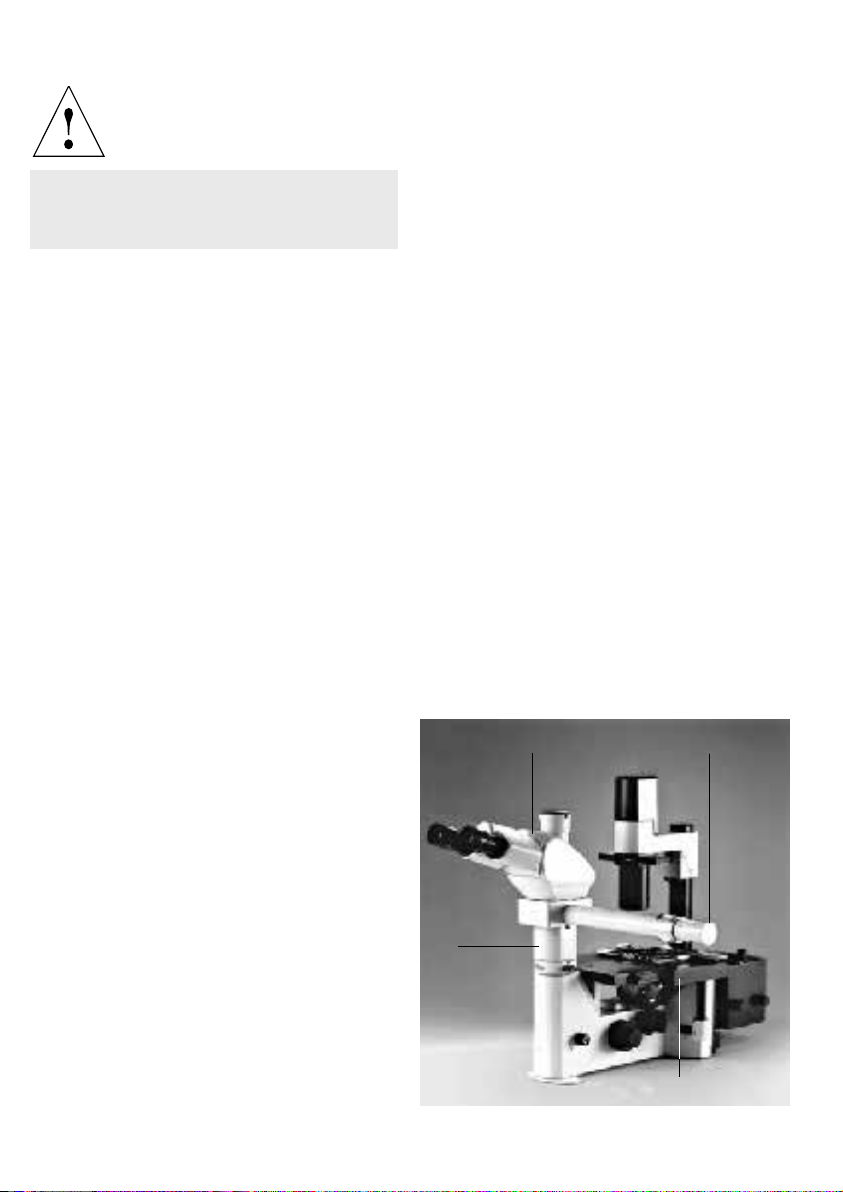
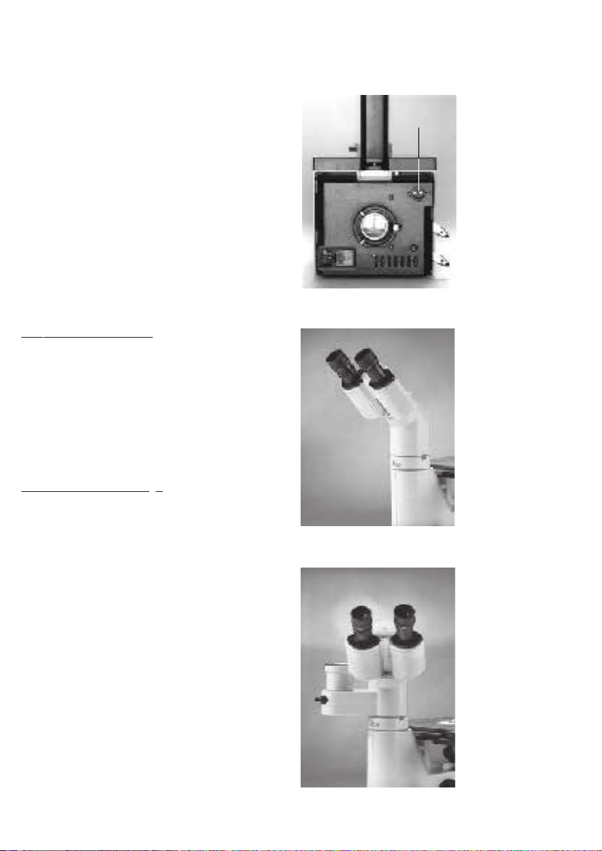
Fig. 1 –3
1 Binocular photo tube DM ILT, 2 Eyepiece tube, 3 Eyepieces,
4 Tube holder, 5 Empty slide or IMC modulator, 6 Integrated
lamp housing with halogen lamp 6 V/35 W, 7 Holder for filter
Fig. 1 Right side of microscope stand
3
2
1
4
5
7
6
Ø 32 mm, 8 Empty slide or modulation or phase contrast slide,
9 Aperture diaphragm, 10 Condenser S 55, 11 Transmitted-
light illumination carrier, 12 Notched lever for condenser
level adjustment, 13 Transmitted-light illumination column,
14 Specimen stage, 15 Objective nosepiece and objectives,
16 Brightness control, 17 Coarse control adjustment and
micrometer adjustment, 18 Power switch, 19 Fluorescence
9
filter blocks, 20 Fluorescence lamp housing, 21 Light stop,
8
22 BG9 Filter, 23 Stabiliser plate, 24 c-mount video adapter,
10
25 Tube adapter IL/L, 26 DM L tubes, 27 Multi-discussion
facility, 28 Condenser S 90
Fig. 3
Microscope stand with DM L tubes and discussion facility
16
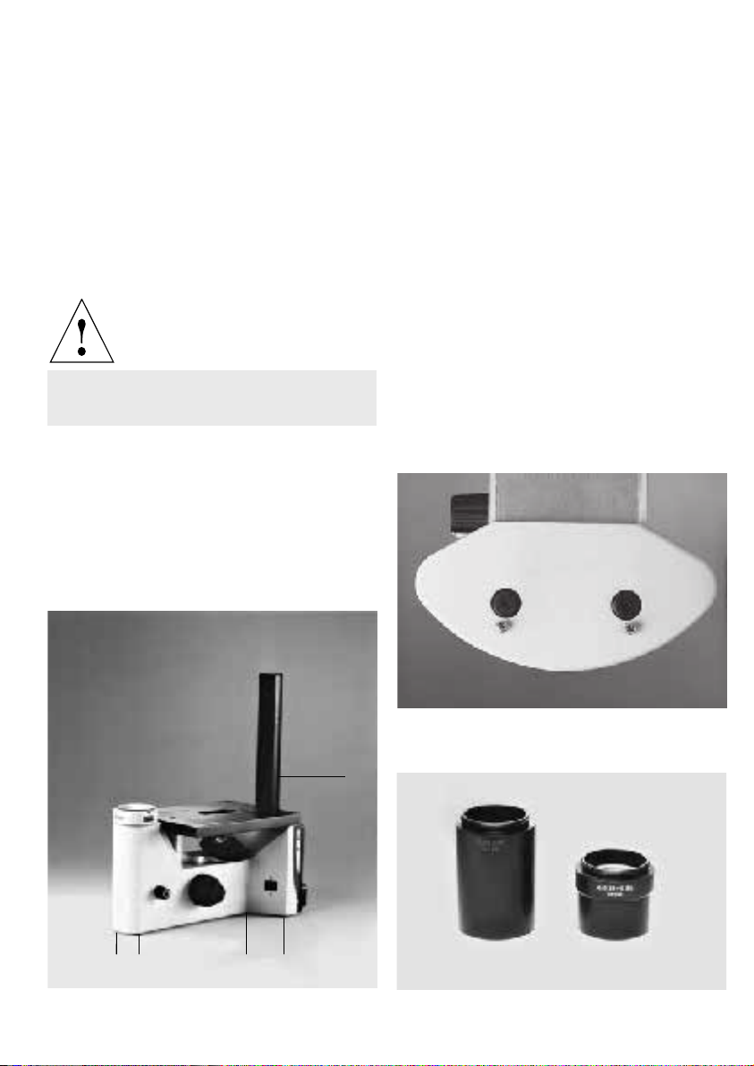
Fig. 2 Left side of microscope stand
13
11
12
20
21
17
22
10
26
28
18
19
25
24
14
15
23
26
27
Page 11

Microscope stand
IL/L tube adapter
Owing to its low centre of gravity, the Leica DMIL
microscope stand is very stable. When using
the multi-discussion facility* or for long-term
exposures in micro-photography applications, a
stabiliser plate* is available to improve stability.
For incident-light fluorescence applications, an
incident-light axis is integrated in a second stand
version.
Tube holder
The tube holder is the interface between the
microscope stand and the tube. The tube holder
permits the use of DM ILB and DM ILT tubes as
well as the IL/L tube adapter which in turn
permits the use of DM L tubes. The ergo module
and the drawing module can also be directly
mounted on the tube holder if the DM ILB or
DM ILT tubes are used (see also Tube adapter).
Tube
The tube contains a 1x tube lense which creates
the primary image in conjunction with the
objective.
The binocular tube consists of a body, the
binocular part, and the tube change ring.
The tube adapter serves to accommodate tubes
from the DM L range as well as the drawing
facility*, the multi-discussion facility*, the
magnification changer*, and the ergo module*.
Eyepieces
The eyepiece creates a magnified, virtual image
of the real intermediate image which is
projected by the objective. In this process, the
eyepieces works as a magnifier.
Transmitted-light illumination unit
The transmitted-light illumination facility consists of the transmitted-light illumination carrier
and the transmitted-light illumination column.
The transmitted-light illumination carrier contains a pre-centred, bright 6 V/35 W halogen
lamp, as well as a holder for a diaphragm slide,
a holder for a light filter, a condenser and an
aperture diaphragm.
Lamp housing
The Leica DM IL microscope uses an integrated
lamp housing with a 6 V/35 W halogen lamp.
Filters
The trinocular tube offers an additional
documentation output to accommodate photo or
video equipment. A switchable mirror directs
the light 100 % either to the eyepieces or the
photo output.
DM IL tubes can be replaced and rotated.
The filters are usually employed to improve the
contrast of the specimen. They are firmly
mounted in a holder (Ø 32 mm).
Different filters can be inserted into the filter
holder of the transmitted-light ilumination unit.
11
Page 12

Aperture diaphragm
Objective revolver and objectives
The aperture diaphragm determines the
resolution, the depth of field and the contrast of
the microscope image. The best resolution is
obtained when the apertures of the objective
and the condenser are roughly the same.
Attention:
The aperture diaphragm in the illumination light
path is not for setting the image brightness. Only
the rotary brightness adjustment knob or the
neutral density filter should be used for this
purpose.
Condenser
The condenser is a lens system which collects
the light and directs it to the specimen from
the top. The condenser permits to utilise the
numerical aperture in the objective.
Notched lever for condenser level adjustment
The notched lever permits the adjustment of the
condenser height by moving the transmittedlight carrier. The markings on the transmittedlight column indicated the proper height to be
set for the condenser used.
Specimen stages and accessories
The specimen stage is used to support the
specimens to be subjected to microscopic
examination. Several options are available for
different objects, such as speciment controllers,
stage expansions, scanning table, clamps,
heating table etc.
The objective revolver is designed to hold the
objectives. Especially the long-range L-type
objectives are able to compensate for the different thicknesses of vessel bottoms.
All microscope objectives with magnifications
2.5 to 100 can be used. All objectives from the
DM L and DMR range with 25 mm thread are
compatible. A choice of objectives is contained
in chapter ”Specifications; Peformance Data“ or
in the current objective lists that are available
from your local Leica representative.
Brightnessadjustment
The microscope stand contains a 6 V/35 W
transformer for continuous brightness adjustment using a rotary brightness switch.
Coarse and fine focus adjustment
Coarse and fine focus adjustment permits a fast
and precise adjustment of the microscopic
image. Focus adjustment is made by moving the
objective revolver. The stroke length is 7 mm.
Power switch
The illuminated power switch permits to switch
the power supply of the microscope on and off.
Due to the illuminated switch, the operating
state of the microscope can easily be
determined even in darkened rooms.
Fuse holder with voltage selector module
The fuse holder is equipped with two fuses and
a voltage selector module. Depending on the
country of use, the voltage needs to be set to
100 V, 115 V or 230 V (tolerance ± 10%).
12
Page 13

Incident-light fluorescence facility*
The microscrope version with incident-light
fluorescence facility contains the integrated
fluorescence axis and the lamp holder for
mounting of a lamp housing.
Fluorescence filter block slide*
The fluorescence filter block slide holds up to 3
fluorescence filter blocks. The filter block slides
can be moved to three alternative switching
positions.
One position of the slide can also be used as a
bright-field position by leaving it empty (no filter
block inserted).
Lamps and lamp housings* for the
incident-light fluorescence facility
For incident-light fluorescence, an additional
illumination is required. On the DM IL, all lamp
housings of the 106 and 107 ranges can be used.
Depending on the version used, the controls for
the lamp housings are located on the right or left
side.
The LH 106 and LH 107 lamp housings are only
used with a 12 V/100 W halogen lamp which can
be centred in the X/Y plane. Both lamp housings
are not equipped with a reflector but have
diffusing screens, heat-absorbing filters and
focusable aspheric collectors.
The LH 106z lamp housing is similar to the LH 106
lamp housing but has a reflector which can be
centred and focused. It also contains a 4- or 6lens collector (quartz collector on request).
The following lamps can be used with their
special sockets:
Halogen lamp, 12 V/100 W
Hg ultra-high pressure lamp 50 W, AC
Hg ultra-high pressure lamp 100 W, DC, without igniter
Hg ultra-high pressure lamp 100 W, DC, with igniter
Xe ultra-high pressure lamp 75 W, DC, with igniter
1)
This requires to raise the microscope stand with a base to
increase the necessary clearance.
1)
1)
Power unit*
An external power unit is used to regulate the
lamp for incident-light fluorescence and the
corresponding lamp housings.
Modulation slide or phase contrast slide*
The modulation slide or phase contrast slide is
part of a constrasting method, either Integrated
Modulation Contrast (IMC) or phase contrast.
The same slides are used for the S 55 and S 90
condensers, however, with different phase
rings.
If no phase slide or modulation slide is used, it is
also possible to insert an empty slide into the
corresponding holder on the condenser.
IMC modulator*
For the Leica Integrated Modulation Contrast
technique, the IMC modulator is provided in the
microscope stand. (→ p. 47 Operation of IMC).
In the standard version, all DM IL microscopes
are equipped with an empty slide.
13
Page 14
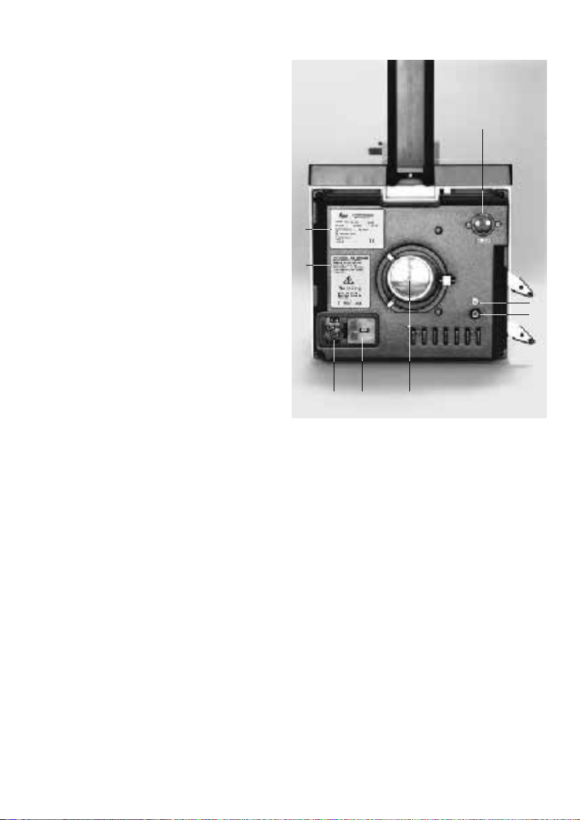
Rear of the microscope
Fig. 4
1 6 V/35 W connection
2 Mains connection
3 Fuser holder with 2 mains fuses
4 Equipotential bonding point
5 Logo for equipotential bonding point
6 Lamp holder (for fluorescence version)
7 Safety note
8 Nameplate
1
8
7
5
4
2
36
14
Page 15

Installation site
Unpacking
The microscope should be operated in a dustfree room which is also free from oil, chemical
fumes, and excessive humidity. Major temperature fluctuations, direct sunlight, and
vibration should be avoided because they can
affect measurements and photomicrography.
Ambient conditions:
Temperature 10 –36 °C
Relative humidity 0 –80 % up to 30 °C
In warm and humid climates, microscopes
require special care to prevent fungal growth.
For additional instructions, please refer to
chapters “Maintenance” and “Storage”.
Attention!
Lamp housings* and power units* must be
located at least 10 cm away from the wall and
combustible objects.
Please compare the delivery carefully with the
packing note, delivery note or invoice. We
strongly recommend that you keep a copy of
these documents with the manual so that you
have the proper information on the time and
scope of delivery at a later time when ordering
more equipment or when the microscope is
serviced. Please make sure that no small parts
are left in the packing material. Some of our
packing material has symbols that indicate that
it can be recycled in an environmental-friendly
manner.
Note
Keep the packing material for the purpose of
storage and transport of the microscope and its
accessories.
Attention!
Avoid touching the surface of the optics lens.
If finger prints are left on the glass surfaces,
use a soft leather or linen cloth to remove
them. Even minute traces of perspi-ration
from fingers can corrode the surfaces of
optical instruments in a very short time. For
additional instructions, please refer to
chapters “Maintenance” and “Cleaning”.
15
Page 16
Attention!
On no account should you connect the
power unit* and peripherals* to the mains
yet!
The following parts can be included in the
delivery:
– Leica DM IL microscope (transmitted-light or
incident-light fluorescence)
– Illumination and condenser carrier
– Tube
– Eyepieces
– Objectives
– Condenser
– Protective cover
– Power cord
– Instruction manual
Optional components:
– IL/L tube adapter
– Phase slide
– Adjustment telescope
– IMC slide
– IMC module
– Filters for transmitted light
– Filter slide for fluorescence blocks
– Fluorescence blocks
– Lamp housing
– Replacement halogen lamp
– Ultra-high pressure mercury lamp
– External power unit
– c-mount video adapter
– Camera
– Speciment stage accessories
– Additional components from the DM L range,
such as tubes, drawing facility, multidiscussion facility, magnification changer,
ergo module
Fig. 5 DM IL microscope with drawing facility and ergo photo
tube
1 Ergo photo tube from DM L range, 2 IL/L tube adapter,
3 Drawing facility, 4 Specimen stage with accessories
1
4
2
16
3
Page 17
Setting up
• As a first step, remove all components from
the shipping and packing material.
• Place the DM IL basic microscope stand in a
sufficiently clear space on a workbench.
• Make sure that all four feet have been
mounted to the bottom of the microscope
stand.
Attention!
On no account should you connect the
microscope to the mains yet!
Fig. 6 Microscope with transmitted-light illumination column
1 Screw for condensor collision protection, 2 Feet
• If the delivery includes a stabiliser plate,
mount this to the bottom of the microscope
stand with two screws so that the two front
feet fit into the recesses (Fig. 7).
Tighten the screws and place the microscope
back on the table in the upright position.
Attaching the condensers
• Screw the S 90 (8.1) or S 55 (8.2) condenser into
the condenser holder (9.2) of the transmittedlight illumination carrier from below.
Fig. 7 Stabiliser plate
Fig. 8
1 S 90 condenser, 2 S 55 condenser
1
2
2
22
1
2
17
Page 18
Positioning the transmitted-light
illumination carrier
• Position the transmitted-light illumination carrier into the column from above while
pressing on the notched lever for the condenser level adjustment (9.5).
• Position the transmitted-light illumination
carrier (9.3) on the transmitted-light illumination
column (9.4) depending on the condensor used
(S 55 or S 90) and release the notched lever.
The markings (9.6) are referred to a liquid
level of 15 mm. For microscopes with dual
markings, the lower line indicates a liquid
level of 15 mm and the upper line indicates a
liquid level of 50 mm.
• Make sure that the transmitted-light illumination carrier is locked in place.
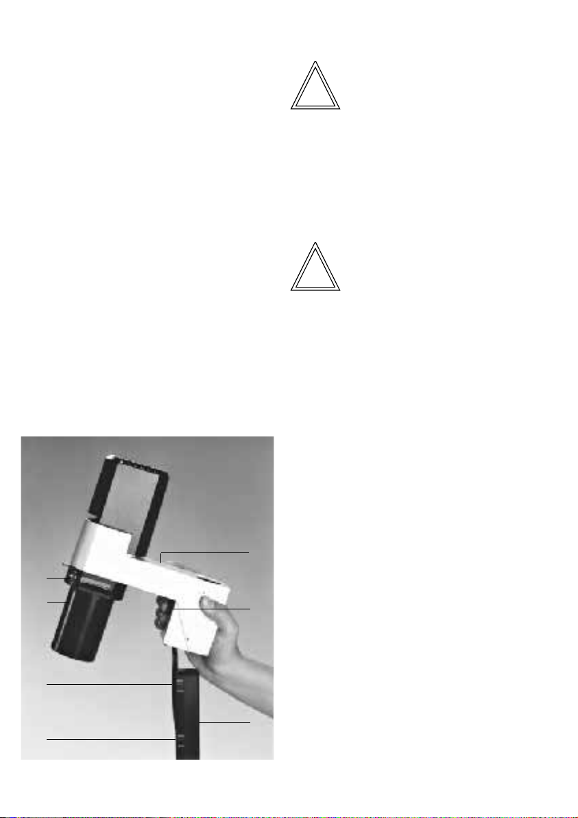
Fig. 9 Transmitted-light illumination unit with condenser
1 Condenser (S 90), 2 Condenser holder, 3 Transmitted-light
illumination carrier, 4 Transmitted-light illumination column,
5 Notched lever for condenser level adjustment, 6 Markings
Note
A screw (6.1) on the transmitted-light illumination column prevents that the condensor
collides with the specimen stage.
Repositioning the transmitted-light illumination
carrier with the specimen stage
Note
For the heating stage* only one position of the
transmitted-light illumination carrier is possible.
This position is determined by the existing holes
in the stage.
Repositioning of the transmitted-light illumination carrier is only possible with the DM ILB or
DMILT tubes.
The specimen stage can be made accessible
from three sides by repositioning it by 180°.
18
3
2
1
6
6
5
4
Page 19
Attention!
Do not loosen the screws (10.1) below the
stage on the transmitted-light illumination
carrier because this would displace the
optical axis.
• Unscrew the screws (11.1) with a 3 mm fixed
spanner and remove the screws.
• Rotate the stage with the transmitted-light
illumination unit by 180°.
• Position the stage with the transmitted-light
illumination unit. The stage should lock in the
guide pins (10.2) on the microscope.
• Insert the screws (12.1) and tighten them.
• Mount the connecting cable in the plastic
guide below the stage (10.3).
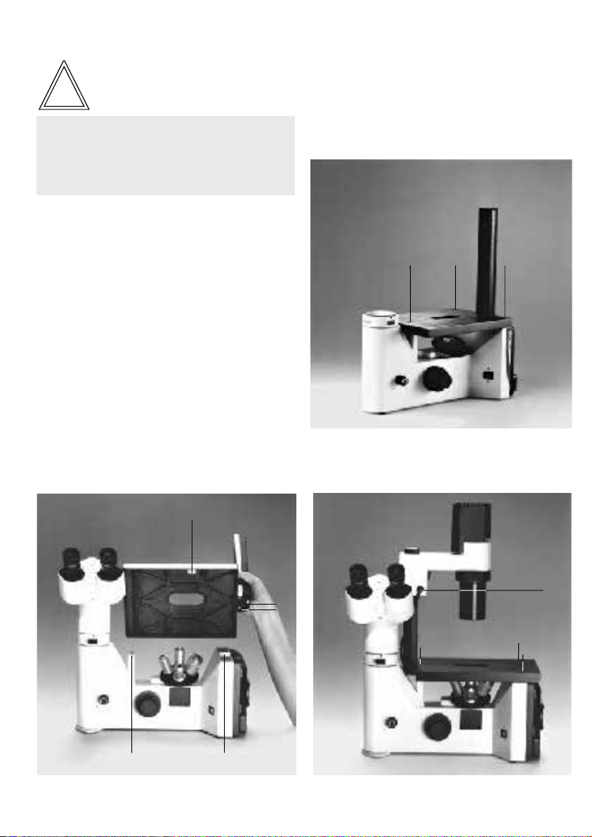
Fig. 11
1 Screws for repositioning the transmitted-light illumination
carrier
1
1
1
Fig. 10
1 Clamping screws for optical exis, 2 Guide pins, 3 Plastic
guide
3
1
1
2
2
Fig. 12
1 Screws for repositioning the transmitted-light illumination
carrier, 2 Connecting cable
2
1
1
1
19
Page 20
Electrical connection of the transmitted-light
illumination carrier
Fig. 13 Rear of microscope
1 Socket for connecting cable
• Use the connecting cable (12.2) to connect
the transmitted-light illumination with the
integrated power supply via the power socket
(13.1) on the rear of the instrument.
Positioning the tubes
The DM ILB tube (Fig. 14 Binocular tube) or the
DM ILT tube (Fig. 15 Binocular photo tube) is
included in the standard delivery. For additional
instructions, refer to chapter “Specifications;
Performance data”.
DM ILB and DM ILT tube
• Loosen the clamp (16.1) use a 3 mm fixed
spanner.
• Insert the tube (16.3) into the tube holder (16.2).
• Retighten the clamp screw.
• To set a new viewing position, loosen the
clamp screw (16.1) and retighten it after
rotating the tube to the desired position.
Tube from the DM L range
In place of the standard DM IL tubes, you can
also adapt one of the following tubes from the
DM L range:
HC LB 0/3/4 and HC LBP 0/3/4 binocular tube
HC L1T 4/5/7 and HC L1TP 4/5/7 trinocular tube
HC L3TP 4/5/7 trinocular tube with 3 switching positions
HC LVB 0/4/4 ergo tube, binocular
HC L1VT 0/4/4 ergo photo tube, trinocular
1
Fig. 14 Binocular tube
Fig. 15 Binocular photo tube
20
Page 21

Proceed as follows:
3
1
2
• Unscrew the lock screw on the tube changer
(16.1) using a 3 mm fixed spanner.
• First place the IL/L tube adapter (17.1) into the
tube holder of the microscope.
• Retighten the lock screw.
• Unscrew the lock screw on the IL/L tube
adapter (17.2).
• Place a tube into the tube holder of the tube
adapter.
• Retighten the lock screw.
• To set a new viewing position, loosen the lock
screw (17.2), rotate the tube as desired and
retighten the lock screw.
Fig. 16
1 Lock screw, 2 Tube holder, 3 Tube
Fig. 17
1 IL/L tube adapter, 2 Lock screw
Note
For mounting a drawing facility*, a multidiscussion tube*, a magnification changer* or
an ergo module*, please refer to chapter
“Setting up the options“.
2
1
Fig. 19 HC L1VT tubeFig. 18 HC L1T tube
21
Page 22

Positioning the eyepieces
The eyepieces are positioned into the eyepiece
connection pieces.
For the DM ILB and DM ILT tubes, use only the
following eyepieces:
10x/18 Br (M),
10x/20 Br (M) or
15x/14 Br
When using a tube from the DM L range, use the
corresponding eyepieces:
HC PLAN 10x/20 (M)
HC PLAN 12.5x/16 M
Widefield 16x/14 Br (M)
Widefield 25x/9.5 Br (M)
+)
also requires a spacer ring
Br) eyepiece for wearer of spectacles
+)
+)
For information on diameter, visible object surface and overall magnification of the microscope,
refer to chapter “Specifications; Performance
data“.
Positioning the graticules*
Graticules can only be retrofitted by the user for
the abovementioned HC PLAN eyepieces. For
the abovementioned eyepieces for the DM ILB
and DM ILT, the graticules need to be retrofitted
at the factory.
Basically, graticules may only be used for eyepieces with adjustable eyelens = Type
!
Important:
M.
Eyepieces 10x/18 M only:
• Unscrew the sleeve from the lower part of the
eyepiece.
• Insert the graticule with the coated side
pointing downwards (in the direction of the
objective) so that any lettering appears the
right way round when observed in the viewing
direction later.
• Screw the sleeve back in.
Eyepieces HC PLAN 10x/20 M and HC PLAN
12.5x/16 M only:
• Unscrew the retainer sleeve from the lower
part of the eyepiece.
• Insert the graticule with the coated side
pointing downwards (in the direction of the
objective) so that any lettering appears the
right way round when observed in the viewing
direction later.
• Screw the retainer sleeve back in.
Positioning the photo eyepieces*
The HC PLAN viewing eyepieces are designed
for direct visual observation. Special eyepieces
with an insertion diameter of 27 mm and the
engraved identification HC...PHOTO are used
for adapting micro-photographic equipment
with fixed magnification, e. g. DM LD and MPS
systems, as well as for special TV adaptation
systems (use the proper adapter!).
Additional information on the adaptation of
photo and video equipment → separate instructions.
Be extremely careful to avoid dust and
fingermarks, since this will be visible in the field
of view.
The graticule diameter is always 26 mm for HC
PLAN eyepieces and 19 mm for the standard
eyepieces for the DM ILB and DM ILT tubes.
22
Page 23
Attaching and removing the objectives
• Remove the screw cap on the objective
threads.
• Screw the objectives into the nosepiece
opening that an incremental change of
magnification is possible (e. g. in
the
sequence 4, 10, 20, 40).
• If objective threads are left unused, cover
these with screw caps to protect the
microscope optics against dust.
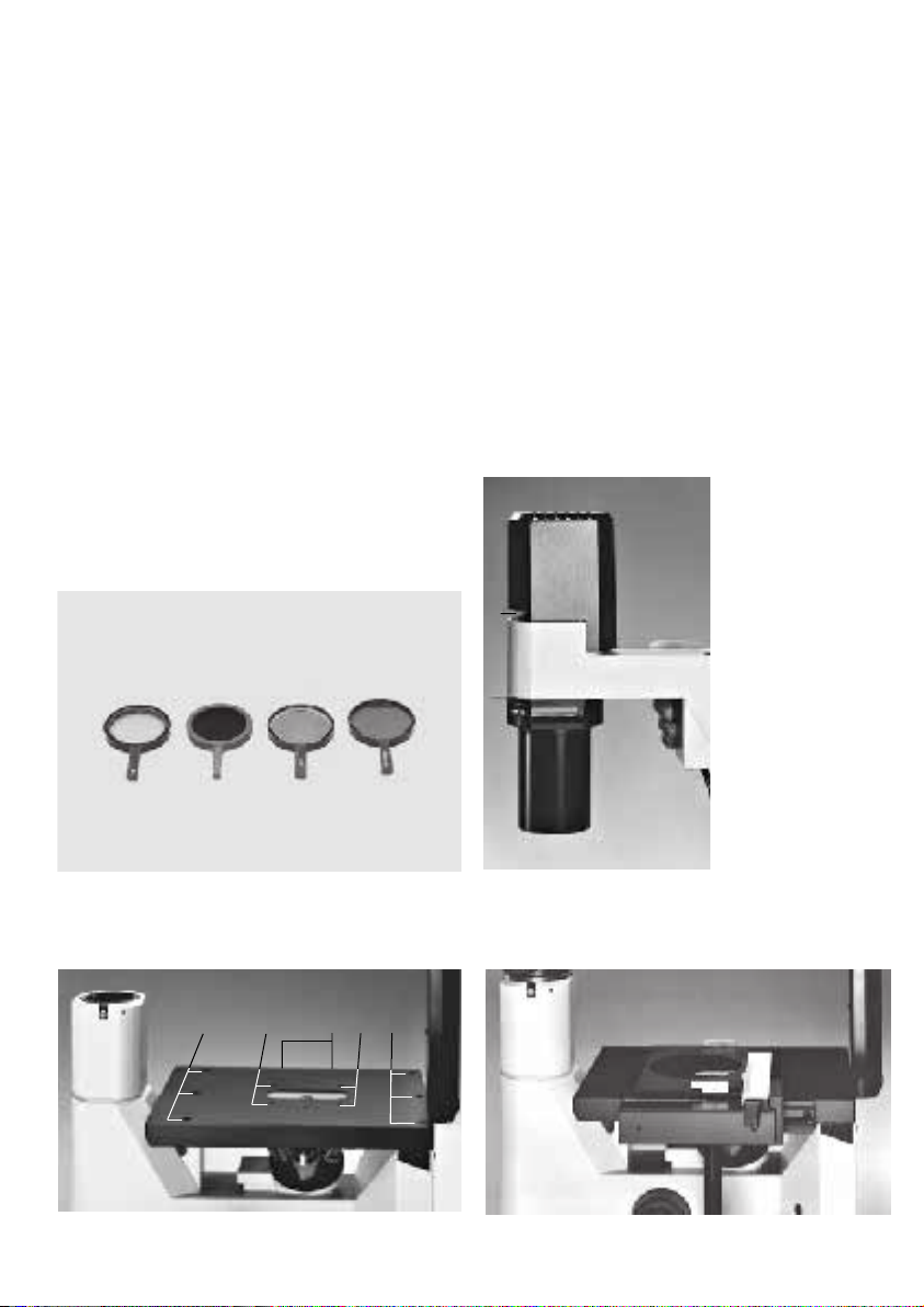
Positioning the filter
• Place the filter (Fig. 20) into the filter holder
(21.1) on the transmitted-light illumination carrier.
Fig. 20 Filter
Attaching the specimen controller
• Attach the specimen controller to the right or
left side of the stage to accommodate brackets
for different culture vessels (22.1).
• Mount the specimen controller with a 3 mm
fixed spanner.
Fig. 21
1 Filter holder
1
Fig. 22
1 Holes for attachable specimen controller, 2 Holes for
specimen brackets, 3 Holes for stage mounting
3
3
1
22
Fig. 23 Specimen controller with holder mounting
23
Page 24
Self-adhesive scales to determine the coodinate
adjustment have been included with the
brackets.
• Attach these in the recesses on the specimen
controller.
Selecting the mains voltage and connecting the
microscope to the mains supply
Attention!
Attaching the stage expansion
• Attach the stage expansions to the right or left
side or to both sides of the stage (22.3).
• Mount the stage expansion with a 3 mm fixed
spanner.
Inserting the specimen brackets
• Insert the specimen brackets into the four
holes provided in the stage opening for this
purpose (22.2).
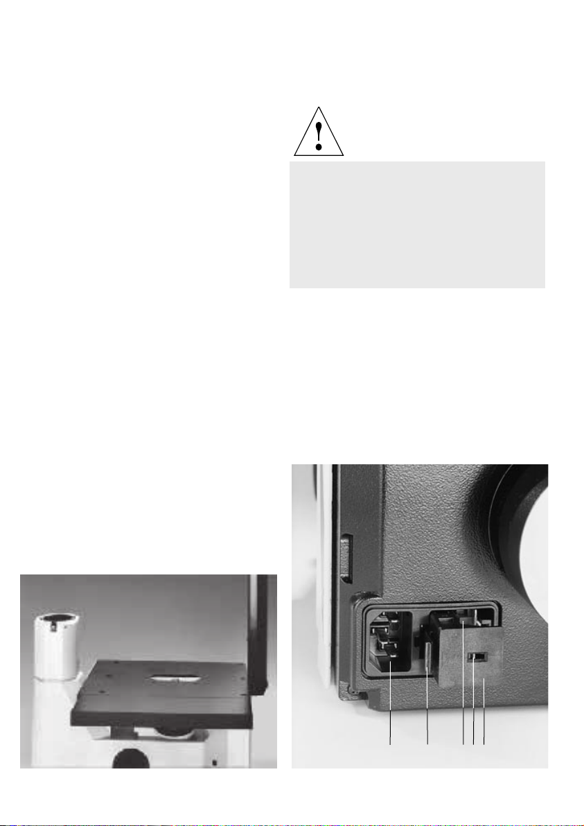
Fig. 24 Specimen stage with expansions attached
Do not plug in the mains plug of the
microscope and of the power unit* before all
the options are assembled.
The mains plug may only be inserted into a
grounded socket. The protection must not be
jeopardised by using an extension cable
without ground conductor.
Fig. 25
1 Fuse holder with voltage selector module, 2 Latch, 3 Voltage
selector module, 4 Mains voltage, 5 Mains connection
24
5
2
4
3
1
Page 25
• Check the voltage setting on the rear panel of
the unit. Depending on the country of use, this
setting can be 100 V, 115 V or 230 V. The voltage setting can be corrected as follows:
• Use a screwdriver to press on the latch
(25.2) and remove the fuse holder (25.1).
• Pull out the voltage selector module (25.3).
• Insert the voltage selector module into the
holder so that the number which corresponds to the desired mains voltage (25.4)
appears on the outside (upside down).
• Insert the fuse holder (2.1) until the latch
clicks audibly in place.
• If you purchased additional options with the
microscope, install these options first (see
next chapter).
Attention!
For external lamp power units, always perform the mains voltage setting as described
in the manual which is supplied separately, or
use a power transformer.
• Then connect the microscope with the power
cord (2.4) and connect it to the mains supply.
Attention!
Observe the safety information on pages 7
and 8!
25
Page 26
Setting up the options
Note
These assembly steps are not required if no additional accessories have been purchased with
the microscope.
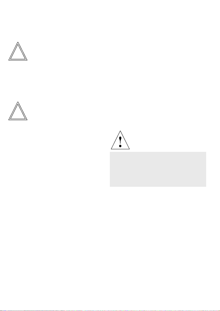
Assembling the fluorescence filter blocks*
Positioning the filter block slide*
• Hold the filter block slide so that the warning
label is positioned is located at the front left
side and insert it into the dovetail holder (26.2)
on the left side of the microscope stand.
• The filter block slide can now be moved
between the three switching positions.
Attention!
!
Note
For microscopes with integrated incident-light
fluorescence facility only.
The filter block slide (Fig. 26) accommodates up
to three fluorescence filter blocks.
• For assembly of the filter blocks, remove the
slide cover (26.5).
• Insert the filter blocks (26.1) into the dovetail
holder (26.2), with the engraved lettering
pointing upward. Make sure that the filter
blocks click in place.
• Reinstall the slide cover.
• Check that the slide cover (26.5) is properly
installed.
• Mark the filter positions using the enclosed
adhesive labels.
The filter block slide is not protected against
inadvertent sliding out.
Attention!
When using an incident-light dichroic mirror
or polarisation dichroic mirror in conjunction
with fluorescence filter blocks, there is a risk
of glare in case of inadventent switching
between positions!
26
Page 27
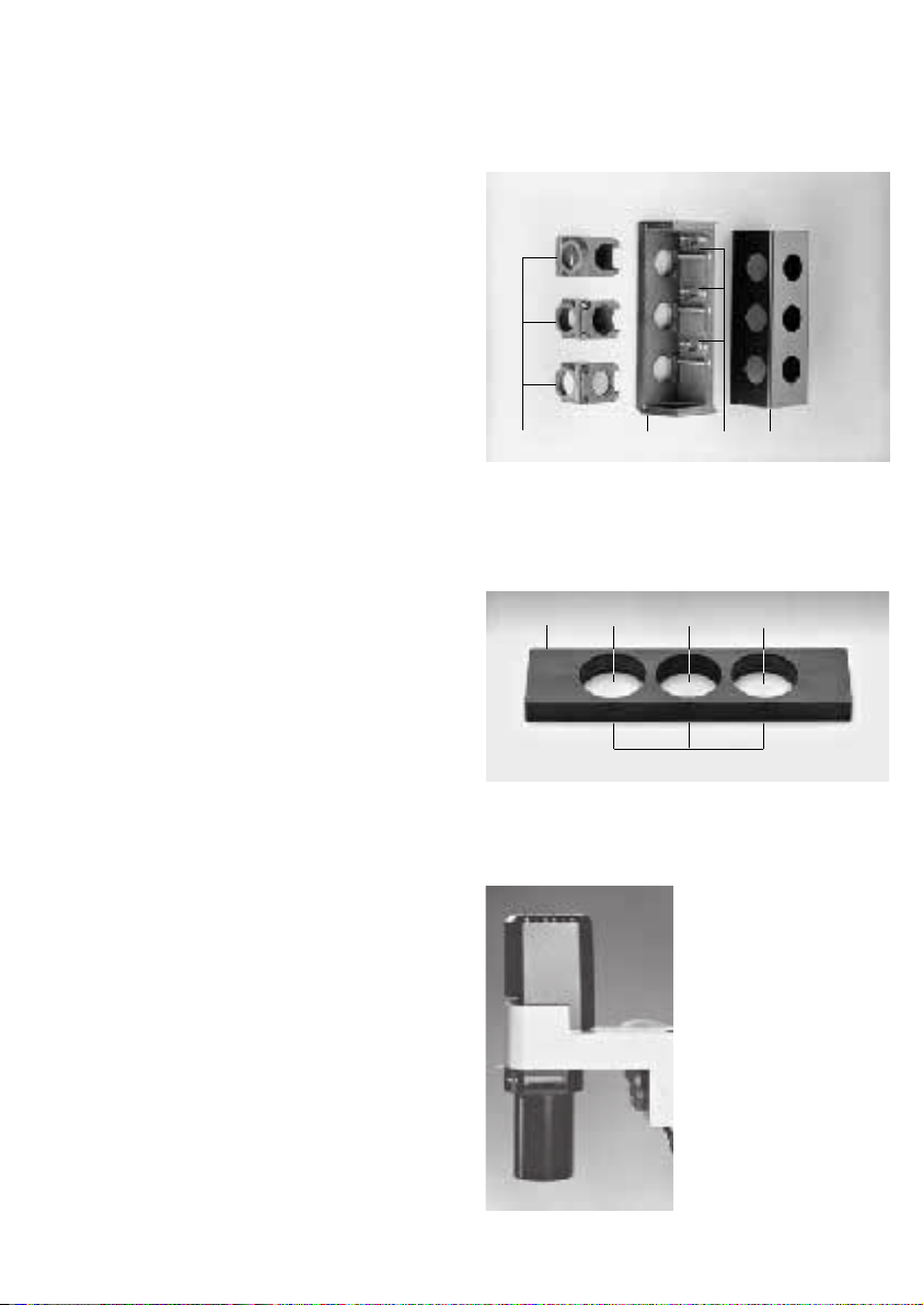
Positioning the phase contrast light rings
The phase contrast light rings are inserted into
the phase contrast slide (Fig. 27). The slide has
two holders which can be centred and a centre
position which is the bright-field position (BF).
• Place the light rings into the centring holders
(27.2) of the slide with the disc pointing
downwards .
• Press on the edge of the light rings until they
click in place. Avoid any pressure on the
centre of the disc because this can break the
webs.
Different sets of light rings are available for the
S 55 or S 90 condensors.
Positioning the phase contrast slide on the
transmitted-light illumination carrier*
Attention!
!
The condenser slide is not protected against
inadvertent sliding out.
• Remove the blank slide if present.
• Hold the condensor slide so that the lettering
points forward. The catches (27.4) are located
on the upper long side of the slide and point
toward the centre of the specimen stage.
• Insert the condenser slide into the transmitted-light illumination carrier from the side
(Fig. 28). The keyways should click in place
when the slide is inserted.
Fig. 26
1 Filter block, 2 Dovetail holder, 3 Slide cover, 4 Lower part of
filter block slide
1
Fig. 27
1 Slide for light rings, 2 Centring holder for light ring, 3 Bright-
field position, 4 Catch
1
Fig. 28 Transmitted-light illumination carrier with holder for
condenser slide
4
2
3
4
3
2
2
27
Page 28

Positioning the IMC slit diaphragm slide* on
the transmitted-light illumination carrier
!
Attention!
The condensor slide is not protected against
inadvertent sliding out.
• Remove the blank slide if present.
• Hold the condensor slide so that the lettering
“Top left“ is located on the left upper side
(29.1) and the other lettering points forward.
The catches (29.2) are located on the upper
long side of the slide and point toward the
centre of the specimen stage.
• Insert the condenser slide into the transmitted-light illumination carrier from the side
(30.1). The keyways should click in place
when the slide is inserted.
Positioning the IMC modulator*
• Remove the blank slide if present.
• Insert the IMC modulator so that the lettering
(29.3) points forward.
• Lock the slide in position BF (lettering BF is
visible) or in position IMC (lettering IMC is
visible).
Fig. 29 IMC slit diaphragm slide and IMC modulator
1 Lettering “Top left“ on condenser slide, 2 Catches, 3 Letter-
ing on IMC modulator
1
3
2
3
28
Fig. 30
1 Holder for IMC modulator
1
Page 29
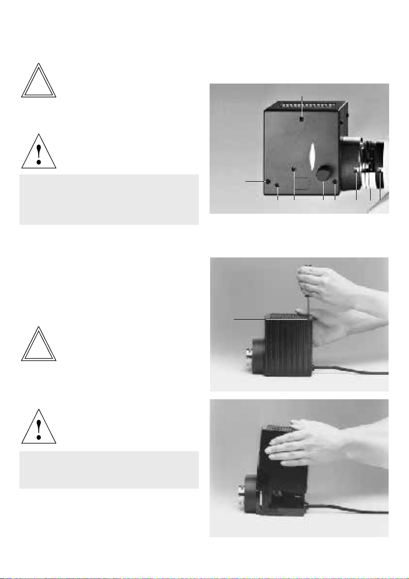
Assembling the 106* or 107* lamp housings
Note
For microscope with integrated incident-light
fluorescence facility only.
Attention!
Fig. 31 Series LH 106 lamp housing
1 Screw for opening of lamp housing, 2, 3 X and Y centring of
lamp*, 4 Focusing of collector, 5, 7 Mounting screws, 6 Filter
holder (intermediate component) for filter Ø 50 mm
1
Prior to making any assembly work, always
disconnect the power supply at the external
transformer outlet and the microscope
outlet!
Replacing or changing the halogen lamp
This procedure is only required if the lamp is not
pre-installed.
• Unscrew the screw on the lid (31.1, 32.1) with
a crosstip screwdriver and remove the lid
(Fig. 33).
• Move the collector to the front.
Note
This step is not required for the 107/2 lamp
housing.
Attention!
Leave the protective covering on the lamp
until the lamp is in its holder! Avoid making
finger prints or wipe them off immediately.
1
3
Fig. 32/33 Opening the LH 107 lamp housing
1 Screw for opening of lamp housing
1
45
2
1 6
7
29
Page 30
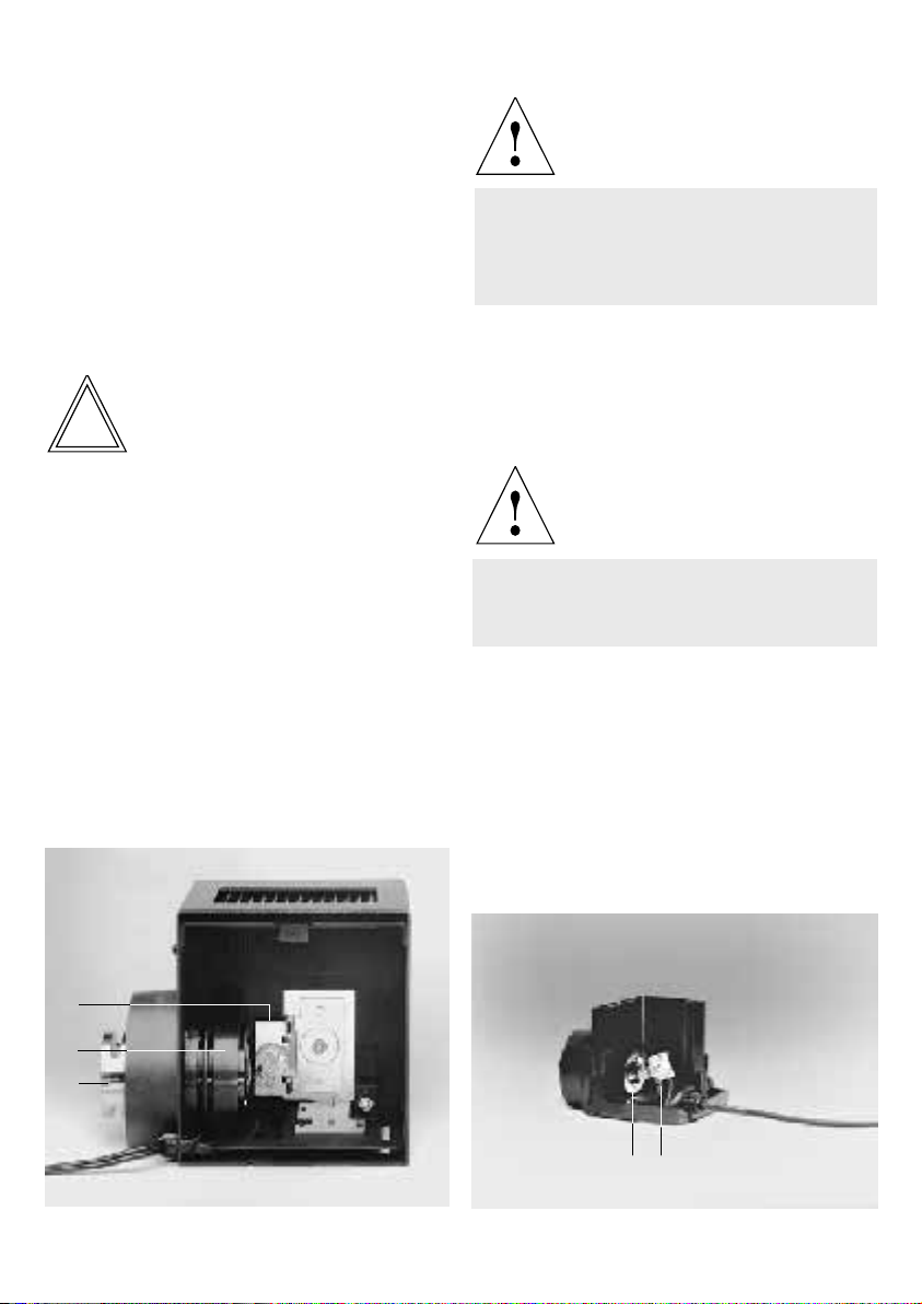
• Place a new 12 V/100 W halogen lamp straight
into the lamp holder (34.1).
• Move the collector back to its original
position.
• Replace the lid and fix it with the screw (31.1,
32.1).
• Connect the lamp housing to the power unit:
Assembling the 106 z* lamp housing with
halogen lamp
Note
For microscope with integrated incident-light
fluorescence facility only.
Attention!
Prior to making any assembly work, always
disconnect the power supply at the external
transformer outlet and the microscope
outlet!
• Unscrew the lock screws (36.4 and 36.9) with
a crosstip screwdriver.
• Slightly pull out the cut-out plug (36.11) from
the socket and flip up the lid (36.1).
Attention!
Leave the protective covering on the lamp
until the lamp is in its holder! Avoid making
finger prints or wipe them off immediately.
Fig. 34 LH 106 lamp housing, opened
1 Lamp holder with 12 V/100 W halogen lamp, 2 Collector,
3 Diffuser
1
2
3
30
Fig. 35 107/2 lamp housing, opened
1 Collector, 2 Lamp holder with 12 V/100 W halogen lamp
21
Page 31

• Unscrew the lock screws (36.10) on the lamp
holder and remove the lamp holder (Fig. 37).
• Insert a new 12 V/100 W halogen lamp into the
lamp holder.
• Insert the lamp holder and fix it with the
screws (36.10).
• Plug the cut-out plug into the socket (36.11).
• Flip the lid back down and tighten the screws
(36.4 and 36.9) on the lid.
• Mount the lamp housing and fix it on the
microscope with the lock screw.
• Connect the lamp housing to the power unit.
Connecting to the 12 V/100 W power unit*
The Leica 12 V/100 W power unit is an autoranging power supply. It supplies halogen lamps up
to 12 V.
Be careful when unpacking the power unit.
Do not operate the unit in the presence of strong
vibration, large temperature fluctuations, high
humidity and direct sunlight.
Position the unit so that the ventilation openings
are clear. Keep a safety distance of 10 cm from
walls or other equipment.
Fig. 36 106 z lamp housing, opened
1 Lid, flipped up, 2 Collector, 3 12 V/100 W halogen lamp or gas
discharge lamp (see Fig. 40), 4, 9 Lid mounting, 5 Reflector,
6, 8 Adjusting screws for x/y centring of reflector, 7 Focusing
of reflector, 10 Mounting screws for lamp holder, 11 Socket
for cut-out plug
1
2
3
4
10
11
10
5
6
7
8
9
31
Page 32

A rotary knob is located on the front panel of the
power unit which is used to set the desired
voltage. The setting range is between approx.
2.5 V and approx. 12 V. The 10.5 V setting has a
marking and corresponds to a colour temperature of 3200 K. This position has been preset at
the factory.
The On/Off switch and the ports for the mains
plug and the lamp are located on the rear panel
of the unit. The “Control“ port is currently not
used.
Connect the lamp housing to the corresponding
port. When using a lamp housing with shielded
cable (e. g. the 107/2 lamp housing), screw the
shield connection to the equipotential bonding
point. Connect the power unit to the mains. It is
not required to preselect the mains voltage.
Switch on the unit with the On/Off switch (Position 1).
Assembling the 106 z* lamp housing with
Hg and Xe lamps
Note
For microscope with integrated incident-light
fluorescence facility only.
The following gas discharge lamps (with different lamp holders) can be used in addition to
halogen lamps (Fig. 40):
Hg ultra-high pressure lamp 50 W, AC
Xe ultra-high pressure lamp 75 W, DC, stabilised
Hg ultra-high pressure lamp 100 W, DC, stabilised
Hg ultra-high pressure lamp 100 W, DC, stabilised, with igniter
Fig. 37 Front panel of 12 V/100 W Leica
32
Fig. 38 Rear panel of 12 V/100 W Leica
1 Equipotential bonding point
1
Page 33

Attention!
– Prior to making any assembly work, always
disconnect the power supply at the
external transformer outlet and the
microscope outlet!
– Allow the lamp housing to cool prior to
opening it (at least 15 min.), explosion
hazard!
– Never touch the glass parts of the burner
with your hands. If required, carefully
remove finger prints and dust (use alcohol
if necessary).
– Adjust lamps immediately after ignition.
– Avoid frequent switching on and off
because this could affect the service life
(→ p. 76) and stability. Hot Hg lamps will
ignite only after cooling off. It is recommended to run in new burners for a couple
of hours without interruption.
– Make sure that the lamp housing is
sufficiently ventilated. Never block air slots
with paper etc., fire hazard!
– It is good practice to record the hours of
use and to compare them to the manufacturer’s specifications.
Replace discoloured, worn burners in due
time.
– We must refuse any liability for damage
resulting from a possible explosion of the
lamp.
• Insert the burner as follows while strictly
observing the above safety instructions:
• If a plastic protective sleeve is present,
leave it in place for the time being.
• Insert the burner so that the lettering is
upright after installation. For Hg 50, Hg 100,
and Xe 75, the different height of the metal
base ensures installation at the proper
height.
• Align any existing glass fused nipple (40.2)
by rotating the burner so that the nipple is
orientated to the side and away from the
beam path.
• Insert the upper pin of the burner between
the clamps of the flexible power supply and
fix it with the screw (40.1) .
• Slightly unscrew the stud (40.4) in the hol-
der.
• Insert the burner into the lower end of the
metal base and retighten the stud.
• Remove the protective sleeve of the burner
if it is still present.
Fig. 39 12 V/100 W lamp holder
• If required, disconnect the mains plug of the
power unit and the microscope.
• Open the 106 z lamp housing by slightly
loosening the screws (36.4), pulling out the
cut-out plug from the socket (36.11) and
flipping up the lid of the lamp housing.
• Unscrew the safety screws (36.10) and pull
out the lamp holder (Fig. 39, 40).
33
Page 34

• Place the lamp holder with the burner
inserted into the lamp housing and tighten the
screws (36.10).
• Close the lid of the lamp housing.
When closing the lamp housing, make sure
that the pins of the cut-out plug engage in the
sockets provided for this purpose.
• Retighten the screws of the lid.
• Push the cut-out plug fully in.
• Attach the lamp housing and fasten it to the
microscope with the lock screw.
• Connect the lamp housing to the power unit
(compare mains voltage!):
The Hg 50 W lamp is properly installed if:
1. The type is stamped on the lower socket of
the lamp. The stamped lettering should be
visible, i. e. not upside down.
2. The upper base is marked “UP”.
Note:
An incorrect installation will reduce the lamp
brightness to about 60 % and will considerably limit the useful life of the lamp.
!
Make sure that the markings on the lamp base
and on the power unit are the same. For example,
if the lamp base is marked L1, L1 must also be
set on the power unit to make full use of the
lamp and not to shorten its life.
!
Make sure to dispose of worn burners in an environmental-friendly manner.
Attention:
Important:
34
Page 35

Fig. 40 Lamp holders for gas discharge lamps
1 Upper clamp, 2 Fused nipple of burner, 3 Lower clamp, 4, 6 Mounting holes for holder, 5 Sockets for cut-out plug,
7 Protective sleeve
Hg 50
1
2
4
5
6
Hg 100
Xe 75
with igniter
3
1
7
3
Hg 100
1
3
with igniter
1
3
35
Page 36

Adaptation of imaging systems on binocular
photo tubes*
The binocular photo tubes provided for the Leica
DM IL can be used to adapt an imaging system,
e. g. video camera, reflex camera or automatic
photo system (e. g. Leica MPS 48/52).
Microphotography
Requirements for the adaptation of microphotographic equipment include a trinocular tube, a
HC PHOTO eyepiece adapter tube and HC PHOTO
eyepieces with 27 mm insertion diameter. If the
microphotographic equipment is not provided
with a special viewing port to limit the format, it
is necessary to use HC PLAN M eyepieces, i. e.
with focusable eyelens and photo graticule
inserted, in the binocular viewing port. For additional details, please refer to the manual
supplied with the photo equipment.
TV adaptation
Different adapters are available for connecting
TV cameras with c-mount and B-mount objective thread. The adapters listed in the table
below can be used on all trinocular photo tubes,
although some tubes require an additional photo
adapter tube. The picture area on the monitor
depends on the adatapter used and on the chip
size of the camera.
Calculation of the magnification on the monitor
The magnification V
on the monitor can be
TV
calculated using the equation below or
measured with an object micrometer and a cm
scale.
V
= Objective magnification x
TV
Magnification changer* factor x
TV adapter magnification x
Monitor diameter
Chip diameter of camera
Recorded picture diagonal in mm for
1-inch
2
/3-inch1/2-inch1/3-inch
camera camera camera camera
Without zoom magnification:
c-mount adapter 1x HC 16 11 8 6
c-mount adapter 0.63x HC
+)
– 17.5 12.7 9.5
c-mount adapter 0.5x HC ––16 12
c-mount adapter 0.35x HC –––17.1
c-mount adapter 4x HC
+)
4 2.8 2 1.5
With zomm magnification (Vario TV adapter):
c-mount, 0.32 –1.6x HC ––19
++)
– 518– 3.8
B-mount, 0.5 –2.4x HC ––16 –3.3 –
B-mount, 0.5 –2.4x HC
+)
in preparation
+)
–––12 –2.5
++)
zoom factor 0.42 x and higher only!
36
Page 37

The procedure for positioning the drawing
facility, the multi-discussion facility, the magnification changer, and the ergo module is basically
the same. The drawing facility or the ergo
module can either be mounted directly on the
basic microscope stand (in conjunction with the
DM ILB or DM ILT tubes) or on the DM IL/L tube
adapter (in conjunction with L-tubes).
Positioning the multi-discussion facility*
Note
When using the multi-discussion facility, the
stabiliser plate should also be mounted (→ p. 17).
Positioning the drawing facility*
• Unscrew the lock screw (41.1) on the micro-
scope stand using a 3 mm fixed spanner.
• When using the DM IL/L tube adapter:
• Attach the IL/L tube adapter (41.2).
• Retighten the lock screw (41.1).
• Unscrew the lock screw (41.4) on the tube
adapter.
• Insert the drawing facility (41.3) into the tube
holder of the basic microscope or of the IL/L
tube adapter.
• Retighten the lock screw (41.4).
• Unscrew the lock screw on the drawing
facility.
• Position the tube.
• Retighten the lock screw on the drawing
facility.
Fig. 41 Microscope with drawing facility
1 Lock screw, 2 IL/L tube adapter, 3 Drawing facility, 4 Lock
screw
3
• Unscrew the lock screw (41.1) on the microscope stand using a 3 mm fixed spanner.
• Attach the IL/L tube adapter (41.2).
• Retighten the lock screw (41.1).
• Unscrew the lock screw (41.4) on the tube
adapter.
• Insert the multi-discussion facility (42.1) into
the tube holder of the adapter.
• Retighten the lock screw (41.4).
• Unscrew the lock screw on the multi-
discussion facility.
• Position the tube.
• Retighten the lock screw on the multi-
discussion facility.
Fig. 42 Microscope with multi-discussion facility
1 Multi-discussion facility
4
2
1
1
37
Page 38

Positioning the magnification changer*
(not shown)
• Unscrew the lock screw (41.1) on the microscope stand with 3 mm fixed spanner.
• Attach the tube adapter IL/L (41.2).
• Retighten the lock screw (41.1).
• Unscrew the lock screw (41.4) on the tube
adapter.
• Insert the magnification changer into the tube
holder of the adapter.
• Retighten the lock screw (41.4).
• Unscrew the lock screw on the magnification
changer.
• Position the tube.
• Retighten the lock screw on the magnification
changer.
Positioning the ergo module* (not shown)
• Unscrew the lock screw (41.1) on the microscope stand with 3 mm fixed spanner.
• When using the DM IL/L tube adapter:
• Attach the IL/L tube adapter (41.2).
• Retighten the lock screw (41.1).
• Unscrew the lock screw (41.4) on the tube
adapter.
• Insert the ergo module into the tube holder of
the basic microscope or of the IL/L tube
adapter.
• Retighten the lock screw (41.4).
• Unscrew the lock screw on the ergo module.
• Position the tube.
• Retighten the lock screw on the ergo module.
38
Page 39

Operation
Basic setting for
transmitted light
Attention!
Be especially careful when making examinations which involve the use of acids or
other aggressive chemicals. Avoid direct
contact of these substances with optical
and mechanical parts.
Switching on the 6 V/35 W halogen lamp
• Switch on the 6 V/35 W halogen lamp with the
power switch (43.2) (position I = On).
• Adjust the brightness with the rotary knob
(43.1).
Adjustment specimen
For the initial adjustment of the microscope it is
recommended to use a specimen that contains
areas of high and low contrast.
For incident-light fluorescence of transparent
objects, adjust in transmitted light first.
Fig. 43
1 Brightness adjustment knob, 2 Power switch, 3 Focusing
mechanism
3
1
2
39
Page 40

Focusing on the object
• Set the desired objective. For this purpose,
lower the objective nosepiece first. Use the
black knurled grip on the nosepiece to move
the objective into the light path. Make sure
that the nosepiece clicks audibly in place.
• Use the coarse and fine adjustment to focus
on the object; this will vary the height of the
objective nosepiece while the stage level will
remain the same. The overall travel is 7 mm.
The focusing range (in air) is from 1.0 mm
below to 6 mm above the stage surface.
Attention!
Depending on the objective used, the objective nosepiece must be lowered before
changing the objective position. Otherwise
the objective may collide with the stage.
Adjusting tubes and eyepieces
If you wear glasses, you should remove or fold
back the glare protection on the eyepieces but
make sure to put it on if you are not wearing
glasses.
• Set your interpupillary distance by pulling the
eyepiece tubes apart or pulling them closer
together until you see a single superimposed
image instead of a double image.
• Note your personal interpupillary distance.
• Additional procedure for ergo tubes: Set the
viewing angle (0° –35°) by tilting the binocular
viewing port. To avoid fatigue symptoms, vary
the viewing angle from time to time.
• Close any unused tube exits as stray light may
otherwise disturb viewing.
DM ILB binocular tube
Only for eyepieces with graticule* inserted:
• Largely defocus the object or remove it from
the beam path.
• Focus the graticule with the eye relaxed by
adjusting the eyelens. (The eye relaxes most if
you look temporarily at a distant object
outside the frame.)
• Focus the object only through the eyepiece
with the graticule.
• Then close the eye and focus the object by
adjusting the second eyepiece only.
40
Page 41

Only when no graticule is inserted in both
eyepieces:
• Largely defocus the object or remove it from
the beam path.
• Adjust the eyelens so as to focus on the
boundary of the field of view. When adjusting
the eyelens you will see a bright line around
the body of the eyepiece. This line shows the
correct position of the eye-lens for people
with normal eyesight and for wearers of
glasses who look through the microscope
with corrective glasses.
Remove glasses with bifocal or progressive
lenses before looking through the micro-scope.
• Focus the object through the eyepieces.
Only if one eyepiece has no adjustable
eyelens:
• Focus the object through this eyepiece first
(close your other eye).
• Focus the image again by adjusting the
eyelens of the second eyepiece.
Correction for defective vision
• Look through the right eyepiece with your
right eye and use the fine adjustment to focus
on the specimen.
• Then look onto the same spot of the specimen
with your left eye and rotate the left eyepiece
connection piece until the point on the object
is sharply focused. Do not use the fine
adjustment to achieve this.
• If eyepieces with adjustable eyelenses are
used, do not correct for defective vision by
adjusting an eyepiece tube but by adjusting
the eyelens of the eyepiece.
DM ILT trinocular tube
• Switch the beam splitter to visual obser-vation
by moving the rod. The meaning of the
switching positions is marked with symbols on
the lateral face of the tube.
Rod retracted = visual
Rod inserted = photo
• Adjustment of the eyepieces is made in the
same manner as for the binocular tube.
• Correct for defective vision by adjusting the
eyelens of the eyepiece.
Fig. 45 DM ILT tubeFig. 44 DM ILB tube
41
Page 42

Operation of objectives
Immersion objectives
OIL: Use optical immersion oil in compliance
with DIN/ISO only.
Cleaning → p. 57, Labelling → p. 67 pp.
Attention:
Observe the safety instructions for immersion oil!
W: Water immersion. The special water
immersion objectives with a ceramic front can
be used for all aqueous solutions.
IMM: Universal objective for water, glycerine,
oil.
Colour codes of objectives → p. 69
Locking of objectives
Some immersion objectives (identified by a
knurled grip) can be virtually shortened (locked).
This stops any remaining drops of immersion liquid from inadvertently wetting objectives and
other objects.
• Push in the front part by about 2 mm in the
direction of the nosepiece.
• Lock the objective by rotating it slightly.
!
Attention:
The locking mechanism must always be
released before the immersion objective is used
again, since otherwise the spring mechanism
protecting the speciment and the objective is
ineffective and the other objectives are no
longer parfocal with the immersion objective.
CORR objectives
These are special objectives which can be
adjusted to different coverglass thicknesses.
• Adjust the correction mount coarsely to an
average or estimated value by using the
knurled grip.
• Focus the preparation.
• Readjust the correction mount until you obtain
an optimum contrast, which may require
refocusing with the fine adjustment.
42
Page 43

Operation of transmitted light
Bright-field illumination
Illumination methods which show object-free
areas of the specimen as the brightest parts of
the image are called bright-field. Bright-field
illumination requires absorbing object structures, i. e. staining of the specimen is useful in
most cases. Alternatives are optical contrast
methods, such as phase contrast or modulation
contrast.
Adjusting the condenser
To aid in proper level adjustment of the S 90 und
S 55 condensers, markings (46.1) are located on
the column. These markings indicate a liquid
level of 15 mm. For microscope stands with dual
markings, the lower line indicates a liquid level
of 15 mm while the upper line indicates a liquid
level of 50 mm.
• Press the catch lever (46.2) and adjust the
incident-light illumination carrier until the
upper edge of the carrier and the corresponding condenser level marking match.
Adjusting the aperture diaphragm
The aperture diaphragm (46.3) determines
resolution, depth of field, and contrast of the
microscope image. The best resolution is
obtained when the apertures of the objective
and of the condenser are roughly the same.
Reducing the aperture diaphragm to be smaller
than the objective aperture will reduce the resolution but enhance the contrast. A noticeable
reduction in resolution occurs when the
aperture diaphragm is reduced to less than 0.6x
of the objective aperture and should be avoided
where possible.
• Adjust the aperture diaphragm according to
your subjective impression of the image.
• You may basically achieve a calibration by
comparison with the apertures of different
objectives.
• Visual comparison between the apertures of
the objective and the condenser can be made
as follows:
• Remove the eyepiece from the eyepiece
tube or use an focusing telescope and
focus.
• Close or open the aperture diaphragm until
its image is just visible in the objective pupil
(= brighter circle). This is considered the
standard setting, i.e. condenser aperture =
objective aperture.
• Reattach the eyepiece.
43
Page 44

For low-contrast objects, the aperture diaphragm can be closed further to highlight even
faint specimen details. In polarised light
microscopy, narrowing the aperture diaphragm
usually results in brighter colours.
Attention:
An aperture diaphragm in the objective is usually
fully opened. The reduction in image brightness
caused by stopping down results in:
Better depth of field
Lower coverglass sensitivity
Suitability for darkfield
Change in contrast
The aperture diaphragm in the illumination
beam path is not for setting the image
brightness. Only the rotary brightness adjustment knob or the neutral density filter should be
used for this purpose.
Fig. 46 Transmitted-light illumination unit with condenser
1 Markings, 2 Catch lever for condenser adjustment, 3 Aperture
diaphragm
3
Possible errors
Wrong coverglass thickness or wrong objective.
Specimen has been placed on the stage with the
coverglass upwards instead of downwards.
Aperture diaphragm opened too wide or closed.
Condenser at incorrect level.
Light ring inadvertently used.
IMC component inadvertently used.
Dirty optics.
44
2
1
1
Page 45

Operation of phase contrast
Phase contrast is used to form high-contrast
images of unstained specimens.
• Adjust the condenser level.
• Place the slide with the required light rings
into the holder (47.1).
• Rotate the objective nosepiece to move the
phase contrast objective (engraving PH) with
the lowest magnification into the light path.
• Open the aperture diaphragm (47.4) marked
“PH”.
• Focus the specimen using coarse and fine
adjustment. If it proves difficult to find the
object plane: Temporarily narrow the aperture
diaphragm or use a stained specimen. Set the
condenser disc to the BF position or pull out
the light ring slide. Reopen the aperture
diaphragm.
• Use the light ring (e.g. 1) that corresponds to
the engraving on the objective (e. g. PH 1).
• Centre the light ring as follows:
• Remove one eyepiece from the tube.
• Insert the focusing telescope.
• Loosen the clamp ring on the focusing
telescope and shift it until the light ring
(bright) and the phase ring (dark) are in
sharp focus.
• If the light and the phase rings are greatly
different in dimension, they need to be
matched by varying the condenser level.
• If the light ring is offset laterally against the
phase ring, centre the light ring. To do so,
rotate the centring key in the centring
screws (47.5) until the phase ring covers the
light ring.
Possible errors
Specimen: too thick, too thin, too brightly stained;
identical refractive index of mounting medium
and specimen so that no phase jump occurs.
Attention:
Wedge-shaped coverglass position which
renders the centration of light and phase ring
ineffective.
Wrong light ring, or light ring has been installed
at wrong level.
Aperture diaphragm not opened.
Light ring not centred.
Wrong light ring slide.
IMC modulator in IMC position.
Condenser S 55 and condensor S 90 exchanged.
45
Page 46

Fig. 47
1 Holder for light ring and light segment slide, 2 Transmitted-
light illumination column, 3 Catch lever for condenser level
adjustment, 4 Aperture diaphragm, 5 Centring screws for light
rings, 6 Filter holder Ø 32 mm
1
6
4
3
5
2
Fig. 48
1 Light ring offset against phase ring: no phase contrast,
2 Phase ring fully covers the light ring: phase contrast
46
1
2
Page 47

Operation of
Integrated Modulation Contrast (IMC)
Integrated Modulation Contrast is a special form
of oblique illumination based on the principle of
Hoffman’s modulation contrast.
With this method, a modulator is used to convert
the phase gradients of an unstained object into
amplitude differences.
The impression of a three-dimensional image is
created, similar to a microscopic image with
interference contrast. However, other than with
interference contrast, the object can also be
viewed through double-refracting plastic materials, such as Petri dishes.
Additional benefits of this imaging method
include:
– High contrast
– High resolution
– Halo-free, variable-contrast relief image
– Long working distance of the condenser
– Simple assembly and adjustment
– Applicable for stained and unstained
specimens
Important!
IMC is only possible in conjunction with the S 55
condenser.
Standard bright-field and phase contrast objectives can be used for IMC, which permits to
cover the magnification range from 5x to 100x.
The following objectives are especially suited:
C PLAN 10x/0.22 AP 32.2
C PLAN L 20x/0.30 D
C PLAN L 40x/0.50 D
plus the corresponding phase contrast
objectives.
All other objectives with pupil position D can
also be used.
The following objectives with pupil position C
may also be used with some restrictions:
N PLAN L 20x/0.40 Corr
N PLAN L 40x/0.55 Corr
PL FLUOTAR
(Refer also to Possible errors).
The IMC requires the use of the IMC modulator
(49.1) and the IMC slit-diaphragm slide (49.2).
Positioning the IMC modulator
• Remove the empty slide in the microscope
stand if present.
• Position the IMC modulator so that the
lettering points forward.
• Lock the slide in position IMC (lettering IMC
visible).
The IMC modulator will be flush on either side.
®
L 63x/0.70 Corr
47
Page 48

Positioning the IMC slit-diaphragm slide on the
transmitted-light illumination carrier
!
Attention:
• Remove the empty slide or the phase contrast
slide in the transmitted-light illumination
carrier, if present.
• Hold the diaphragm holder so that the
lettering “Top left“ is located on the top left
side and the other lettering points forward.
The catches are located on the upper long
side of the slide and point toward the centre
of the specimen stage.
• Insert the diaphragm slide from the right side
into the transmitted-light illumination carrier.
• Lock the slide in position IMC (lettering IMC
visible).
Adjusting the slit-diaphragm
• Fully open the aperture diaphragm.
• Select a medium brightness since the line of
light would otherwise appear too bright.
• Switch off any filters which may be switched
on.
• Rotate the objective with the lowest magnification into the beam path, which will usually
be the 10x objective.
• To adjust the slit width, move the slide of the
IMC slit-diaphragm slide to the proper position
for the objective, e. g. to the position marked
10x for the 10x objective.
• Remove one eyepiece and insert the focusing
telescope.
• The line of light will appear as a bright line on
the grey image of the modulator. Focus the
line of light with the focusing telescope.
• Adjust the position of the line of light with the
adjusting screws to the right of the IMC slitdiaphragm slide. A fitting Allen key is supplied
for this purpose.
Do not loosen the screws (49.4) on the slide!
• The line of light must be fully located on the
grey field. With the 10x objective, the image of
the modulator and of the line of light have
almost the same size. Adjust the slitdiaphragm so that the boundary of the bright
line of light is located near the darker edge.
• Move the other objectives with ascending
magnification into the light path one after the
other and check the position of the line of
light. In the case of smaller deviations, find an
intermediate position.
Always make sure that the objective magnification and the slide position on the IMC slitdiaphragm slide match.
Fig. 49 IMC components
1 IMC modulator, 2 IMC slit-diaphragm slide, 3 Catches,
4 Screws
4
2
3
1
48
Page 49

Optimising the IMC (Fig. 49a):
When using the objective with the largest magnification, it may not be possible to adjust the
light slit stop perfectly (in other words, the light
slit cannot be positioned completely on the grey
field, with the result that an offset is noticeable
in either the white or the dark area). In this case,
it is also possible to perform fine adjustments
using the adjusting screw on the IMC modulator
slide.
Use the Allen key to turn this screw to minimise
the offset (to superimpose the grey area and the
illumination slit). After that, swivel the 10x objective back in (followed by the other objectives)
and adjust at the modulator again as described
above. Repeating this operation several times
should mean that offset no longer occurs.
This adjustment generally need to be performed
only once.
Once the IMC is perfectly adjusted, remove the
focusing telescope and replace the eyepiece.
23
4
1
5
Fig. 49a IMC-Components (new)
1 IMC-Modulator, 2 IMC slit-diaphragm slide, 3 Allen key
4
Adjusting screw on the IMC slit-diaphragm slide, 5 Ad-
justing screw on the IMC-Modulator-slide
,
49
Page 50

Possible errors
Short of optimum position of the slit-diaphragm.
Poor image quality due to use of objectives
without pupil position D.
Try improving the image quality as follows:
Reverse the IMC modulator (lettering to the
rear). Adjust the slit so that sufficient coverage
is achieved to avoid glare.
The IMC modulator or the IMC slit-diaphragm
slide are not locked in the IMC position.
Incorrect condenser level or wrong condenser
(only S 55 condenser possible!).
Fluorescence filters are not disabled.
50
Page 51

Operation of incident-light fluorescence
• Open the light stop by moving the lever (50.1).
Note
For microscopes with integrated incident-light
fluorescence facility only.
For the viewing of transparent objects using
incident-light fluorescence, it is recommended
to make an adjustment with transmitted-light
first.
= Light stop moved out of beam path
= Licht stop moved into beam path
• Slide the filter block into the beam path (50.3).
• Position the specimen and focus. The field
diaphragm is installed and pre-centred so that
no adjustment is necessary.
If a reddish background of the specimen
becomes visible with UV excitation, you can
eliminate this effect by moving the BG 38 red
attenuating filter (50.2) into the beam path.
= Filter moved out of beam path
= Filter moved into beam path
Fig. 50
1 Light stop, 2 BG 38 filter, 3 Filter block slide
3
1
2
51
Page 52

Switching on and adjusting the 12 V/100 W
halogen lamp in the 106* lamp housing
• Switch on the 12 V/100 W halogen lamp at the
power unit.
• Open the light stop.
• Move the filter block into the beam path.
• Remove the objective in the beam path.
• Place a white sheet of paper on the specimen
stage.
• Rotate the collector adjustment (51.4) until the
lamp filament (Fig. 52) is clearly projected.
• Use a 3 mm fixed spanner to adjust the
centring screws for level adjustment (51.2)
and for horizontal adjustment (51.3) of the
lamp until the lamp filament is in the centre of
the light spot.
• Remove the paper.
• Position the specimen.
• Check with low objective magnification that
the image is illuminated in a homogeneous
manner.
• Adjust the collector (51.4) if necessary.
Switching on and adjusting the halogen,
Xe and Hg lamps in the 106 z lamp housing*
• Switch on the lamp at the power unit.
• Open the light stop.
• Move the filter block into the beam path.
• Place a white sheet of paper on the specimen
stage.
• Coarsely focus on the surface using a dry
objective with low to medium magnification.
Fig. 51 106 lamp housing (with 12 V/100 W halogen lamp)
1 Screw for opening the lamp housing, 2, 3 X/Y centring of the
lamp (compartment for storing a 3 mm allen key or screwdriver), 4 Collector focusing, 5, 7 Lock screw for mounting,
6 Filter holder (intermediate piece) for 50 mm filter
Items 3 –4 do not apply to the 107 lamp housing
1
1
1 6
3
45
2
7
52
Fig. 52 106 lamp housing
Reflection of the lamp filament, greatly schematised: In
reality, the reflection is extremely low in contrast, the bright
overlap area is wider and less defined. With the 106 z lamp
housing, the reflection is rotated by 90°.
Page 53

• Use a pen to draw a mark in the centre of the
bright surface.
• Remove the objective in the beam path.
• Rotate the collector adjustment (53.6) until the
lamp filament or the discharge arc is clearly
projected.
• Move the reflection of the lamp filament or
the discharge arc to the side (54 a) by rotating
the adjustment screws on the rear of the lamp
housing (53.2 and 53.4).
• Focus the direct image of the lamp filament or
the discharge arc and adjust it as follows:
Fig. 53 106 z lamp housing
1 Level adjustment of lamp, 2, 4 Level and lateral adjustment
of reflection, 3 Mirror focusing, 5 Lateral adjustment of lamp,
6 Collector (focusing of lamp image), 7 Mounting screw
5 1 6 7
2
3
4
For halogen lamp:
• Move the direct image to a position just below
or above your centre mark (54b) or, especially
for higher objective magnifi-cations such as
with the Xe lamp (54c), to the centre, i. e.
superimposed.
• Move the reflection into the brighter circular
area.
• Align the reflection symmetrically with the
direct image (54c). Alternatively, you may also
superimpose the two images as for the Hg and
Xe lamps.
For mercury (Hg) and xenon lamps (Xe):
• Use the horizontal and vertical adjustment
controls of the holder (53.5 and 53.1) to move
the direct image into the centre of the brighter
circular area.
• Move the reflection into the brighter circular
area.
• Focus the reflection.
• Adjust the mirror until the reflection is superimposed to the direct image (54c).
• Remove the paper.
• Position the specimen.
• Check with low objective magnification that
the image is illuminated in a homogeneous
manner.
• Adjust the collector (53.6) if necessary.
Attention!
Be careful not to project the reflection onto
the electrodes as there is a risk of overheating leading to explosion. The two
electrodes can just be seen in the extension
of the symmetry plane of the discharge arc.
53
Page 54

Fig. 54 Schematic view for 106 z lamp housing (in reality, lamp images are less defined)
a direct lamp image focused but out of centre
b direct lamp image in desired position
c indirect and direct lamp images in desired position
Halogen
lamp
Hg
lamp
Xe
lamp
a
b
c
54
Page 55

Possible errors
Weak fluorescence, weak image intensity:
Specimens improperly stored, too old or faded.
Low-contrast image due to:
Excitation bandwidth too wide.
Unspecific staining.
Rapid fading of specimens (e. g. for FITC).
Unspecific filter combination.
Numerical aperture of objectives too low.
Eyepiece magnification too high.
Spent lamp.
Room too bright.
Trinocular tube: incorrect beam splitter setting.
Secondary light due to reflection at condenser.
Fluorescing mounting medium.
Auto-fluorescence of objective or immersion oil.
Dirty glass surfaces.
55
Page 56

Care and maintenance
Cleaning painted parts
Attention!
Disconnect the mains plug before cleaning
and servicing!
Protect electrical components from humidity!
In warm and humid climates, microscopes
require special care to prevent fungal growth.
Clean the microscope after each use and make
sure to keep the microscope immaculately
clean.
Dust and loose particles of dirt can be removed
with a soft brush or lint-free cotton cloth.
Obstinate dirt can be removed with commercially available aqueous solutions, benzine or
alcohol.
To clean painted parts, use a linen or leather
cloth moistened with any of these agents.
Do not use acetone, Xylol or nitro dilutions
which can damage the microscope.
! Attention!
Dust protection
Note
Protect the microscope and its accessories
from dust by putting on the dust cover after each
work session.
Cleaning
! Attention!
Fibre and dust residues can cause disturbing
background fluorescence during fluorescence
microscopy.
Cleaning agents of unknown composition should
be tested on an inconspicuous part of the
microscope. Painted or plastic surfaces must
not be tarnished or etched.
Cleaning the speciment stage
Remove bright spots on the specimen stage by
wiping them off with paraffin oil or acid-free
vaseline.
Cleaning glass surfaces
Remove any dust from glass surfaces with a
fine, dry, and grease-free artist’s hair brush, by
blowing off with a bellows ball or by vacuuming.
56
Page 57

Carefully remove obstinate dirt on glass
surfaces with a clean cloth moistened with
distilled water. Failing this, you may replace the
distilled water with pure alcohol, chloroform or
benzine.
Removing immersion oil
Attention!
Cleaning the objectives
Attention!
Objectives may not be disassembled for
cleaning. If defects are detected on inside
surfaces, send the objectives to your Leica
representative for repair. We also do not
advise cleaning the inside surfaces of the
eyepieces.
The front lens of objectives can be cleaned as
decribed for “Cleaning glass surfaces“. The
upper lens can be cleaned by blowing dust off
with a bellows ball.
Observe the safety instructions for immersion oil!
First wipe of the immersion oil with a clean
cotton cloth, then wipe over several times with
ethyl alcohol.
Handling acids and alkaline solutions
Take particular care when working with acids or
other aggressive chemicals.
!
Always avoid direct contact of such chemicals
with optical and mechanical parts.
Attention!
57
Page 58

Troubleshooting, lamp/fuse replacement
All Leica instruments are manufactured and
tested with extreme care. However, if you have
cause for complaint, please do not try to make
any intervention on the instrument yourself.
Directly contact your national agency or our
central service department, the Technical
Service in Wetzlar.
Postal address:
Leica Microsystems Wetzlar GmbH
Abt. Technischer Service
Postfach 20 40
D-35530 Wetzlar/Germany
Phone +49 (0) 6441-29 2849
Fax +49 (0) 64 41-29 22 66
Apart from preparation errors (e. g. staining or
wrong specimen vessels) which are beyond the
scope of this manual, there are basically two
categories of defects:
Mechanical defects and
Electrical defects
Mechanical defects
Reference to possible mechanical defects has
already been made in chapters “Setting up“ and
“Operation“.
Basically, these include the improper positioning of constrast-enhancing accessories, the
maladjustment of light rings or the setting of an
improper condenser level.
All these possible errors have been covered in
the previous capters.
Therefore, if you are unable to obtain the
desired microscope image, please read the
corresponding chapters of this manual.
Electrical defects
Electrical defects may include:
1. The lamp on the microscope does not work.
2. No voltage is present.
Check the following possible causes:
The On/Off switch does not work
(no illumination):
• Check that all power cords are properly
connected.
• Make sure that the mains voltage is present at
all power outlets used and has not been
disabled with a master switch.
• After you have ruled out all possible external
causes, it is possible that a fuse of the Leica
DM IL microscope or the power unit is
defective.
58
Page 59

Replacing the mains fuse on the microscope
The integrated transmitted-light lamp does not
work
Attention!
Always disconnect the mains plug!
• Switch off the microscope.
• First disconnect the power cord from the
power outlet and then disconnect it at the
microscope.
• Disconnect the power cord of the power unit
if required.
• Use a screwdriver to press on the latch (55.2)
and remove the fuse holder (55.1).
• Remove the defective fuses from the fuse
holder.
• Replace them with two new fuses of the proper type.
Voltage rating Type
for 100 V 2x T800 mA
for 115 V 2x T800 mA
for 230 V 2x T800 mA
Note
• Make sure that the plug of the lamp cable is
firmly plugged in the corresponding socket on
the rear panel of the DM IL microscope stand.
• The halogen lamp may be defective.
Fig. 55
1 Fuse holder with voltage selector module, 2 Latch,
3 Selector module with voltage indications, 4 Mains voltage,
5 Mains connection
5
2
1
4
3
Replacing the 6 V/35 W halogen lamp
Attention!
Never use replacement fuses with a different
current rating.
• Insert the fuse holder (55.1) until the latch
clicks audibly in place.
• Subsequently connect the power cord (55.4)
to the microscope and to the mains supply.
• If required, connect the power unit to the
mains supply.
Always disconnect the power plug!
Remove the protective sleeve of the lamp only
after inserting the lamp. Avoid finger prints,
and if there are any, always wipe them off.
Caution! Lamp and housing may be hot!
• Switch off the microscope and also the power
unit, if required.
• Disconnect the power cord of the microscope and also of the power unit, if required.
59
Page 60

• Disconnect the mains connection of the
transmitted-light illumination carrier on the
rear of the microscope stand (56.1).
• Use a 3 mm fixed spanner to remove the lamp
housing (57.1).
• Remove the defective lamp.
• Place a new lamp (58.1) into the sockets of the
lamp holder (58.2).
• Position the lamp housing and screw it it in
place with a 3 mm fixed spanner.
• Connect the transmitted-light illumination
carrier to the mains voltage at the rear of the
microscope stand (56.1).
• Connect the microscope and, if required, also
the power unit to the mains supply.
The additional fluorescence lamp does not
work
• Make sure that all cable connections between lamp, power unit, and mains have been
properly established.
Possible causes for the failure of the
fluorescence lamp can be a blown fuse of the
power unit or a defective burner in the lamp
housing.
Fig. 56 Rear of microscope
1 Lamp cable connection
1
Fig. 57
1 Mounting screw for lamp housing
1
Replacing the mains fuse on the power unit*
Attention!
Always disconnect the power plug first!
• Switch off the microscope and the power
unit.
• Disconnect the power cords of the micro-
scope and of the power unit.
• Remove the defective fuse from the fuse
holder.
60
Fig. 58
1 6 V/35 W halogen lamp, 2 Lamp holder
1
2
Page 61

Replacement fuses in compliance with IEC 127-2
and/or UL 198 G and/or manu-facturer type:
Part no: 846-205.000-00
Designation: T 4A
Wickmann 19 195/
Schutter FST
Note
Never use replacement fuses with a different
current rating.
Fig. 59 107/2 lamp housing
1 Screw for opening of lamp housing
1
• Connect the microscope and the power unit to
the mains supply.
Replacing the 12 V/100 W halogen lamp in the
106, 107, 107/2 lamp housings
Ask a Leica field technician to show you the proper procedure for replacing the halogen lamp.
All necessary steps are listed below.
Attention!
Prior to making any assembly work, always
disconnect the power supply at the external
transformer outlet and the microscope outlet!
• Switch off the microscope and the power unit.
• Disconnect the power cords of the microscope and of the power unit.
• Unscrew the lock screw on the microscope
and remove the lamp housing.
Fig. 60 107/2 lamp housing, opened
1 Collector, 2 Lamp holder with 12 V/100 W halogen lamp
21
Fig. 61 106 lamp housing, opened
1 Screw for opening of lamp housing, 2 Lamp holder with
12 V/100 W halogen lamp, 3 Collector, 4 Diffuser disc
1
2
3
4
61
Page 62

• Unscrew the screw (59.1 or 61.1) on the lid
and remove the lid.
• Move the collector (61.3) to the front, if
required.
Note
Attention!
Leave the protective covering on the lamp
until the lamp is in its holder! Avoid making
finger prints or wipe them off immediately.
This step is not required for the 107/2 lamp
housing.
Fig. 62 106 z lamp housing, opened
1 Lid, flipped up, 2 Collector, 3 12 V/100 W halogen lamp or gas
discharge lamp (see Fig. 38), 4, 9 Lid mounting, 5 Reflector,
6, 8 Adjusting screws for x/y centring of reflector, 7 Focusing
of reflector, 10 Mounting screws for lamp holder, 11 Socket
for cut-out plug
1
• Remove the defective lamp.
• Place a new 12 V/100 W halogen lamp straight
into the lamp holder (60.1 or 61.2).
• Move the collector back to its original
position.
• Replace the lid and secure it with the screw
(59.1 or 61.1).
• Attach the lamp housing to the microscope
and secure it with the lock screw.
• Connect the lamp housing to the power unit.
• Connect the microscope and the power unit to
the mains supply.
Fig. 63 12 V/100 W lamp holder
62
2
3
4
10
11
10
5
6
7
8
9
Page 63

Replacing the 12 V/100 W halogen lamp in the
106 z lamp housing*
Attention!
Prior to making any assembly work, always
disconnect the power supply at the external
transformer outlet and the microscope
outlet!
• Switch off the microscope and the power unit.
• Disconnect the power cords of the microscope and of the power unit.
• Unscrew the lock screw on the microscope
and remove the lamp housing.
• Unscrew the screws on the lid (62.4 and 62.9)
with a crosstip screwdriver.
• Slightly pull out the cut-out plug from the
socket (62.11) and flip up the lid.
Attention!
Leave the protective covering on the lamp
until the lamp is in its holder! Avoid making
finger prints or wipe them off immediately.
• Unscrew the mounting screws (62.10) on the
lamp holder and remove the lamp holder
(Fig. 63).
• Remove the defective lamp.
• Insert a new 12 V/100 W halogen lamp into the
lamp holder.
• Insert the lamp holder and secure it with the
screws (62.10).
• Plug the cut-out plug into the socket (62.11).
• Flip the lid back down and tighten the screws
(62.4 and 62.9) on the lid.
• Attach the lamp housing to the microscope
and secure it with the lock screw.
• Conenct the lamp housing to the power unit.
Replacing the Hg and Xe lamps
on the 106 z lamp housing
Attention!
– Prior to making any assembly work,
always disconnect the power supply at
the external transformer outlet and the
microscope outlet!
– Allow the lamp housing to cool prior to
opening it (at least 15 min.), explosion
hazard!
– Never touch the glass parts of the burner
with your hands. If required, carefully
remove finger prints and dust (use alcohol
if necessary).
– Adjust lamps immediately after ignition.
– Avoid frequent switching on and off
because this could affect the service life
and stability. Hot Hg lamps will ignite only
after cooling off. It is recommended to run
in new burners for a couple of hours
without interruption.
– Make sure that the lamp housing is
sufficiently ventilated. Never block air
slots with paper etc., fire hazard!
– It is good practice to record the hours of
use and to compare them to the manu-
facturer’s specifications.
– Replace discoloured, worn burners in due
time.
– We must refuse any liability for damage
resulting from a possible explosion of the
lamp.
63
Page 64

• If required, disconnect the mains plug of the
power unit and the microscope.
• Open the 106z lamp housing by loosening the
screws (62.4), slightly pulling out the cut-out
plug from the socket (62.11) and flipping up the
lid of the lamp housing.
• Unscrew the safety screws (62.10) and pull
out the lamp holder (Fig. 64).
• Insert the burner as follows while strictly
observing the above safety instructions:
• If a plastic protective sleeve is present, leave
it in place for the time being.
• Insert the burner so that the lettering is
upright after installation. For Hg 50, Hg 100,
and Xe 75, the different height of the metal
base ensures installation at the proper height.
• Align any existing glass fused nipple (64.2) by
rotating the burner so that the nipple is
orientated to the side and away from the
beam path.
• Insert the upper pin of the burner between the
clamps of the flexible power connection and
fix it with the screw (64.1) .
• Slightly unscrew the stud (64.4) in the holder.
• Insert the burner into the lower end of the
metal base and retighten the stud.
• Remove the protective sleeve of the burner if
it is still present.
• Place the lamp holder with the burner
inserted into the lamp housing and tighten the
screws (62.10).
• Close the lid of the lamp housing.
When closing the lamp housing, make sure
that the pins of the cut-out plug engage in the
sockets provided for this purpose.
• Retighten the screws of the lid.
• Push the cut-out plug fully in.
• Attach the lamp housing and fasten it to the
microscope with the lock screw.
• Connect the lamp housing to the power unit
(compare mains voltage!):
The Hg 50 W lamp is properly installed if:
1. The type is stamped on the lower socket of the
lamp. The stamped lettering should be visible,
i. e. not upside down.
2. The upper base is marked “UP”.
Note:
An incorrect installation will reduce the lamp
brightness to about 60% and will considerably
limit the useful life of the lamp.
!
Attention:
Make sure that the markings on the lamp base
and on the power unit are the same. For
example, if the lamp base is marked L1, L1 must
also be set on the power unit to make full use of
the lamp and not to shorten its life.
!
Important:
Make sure to dispose of worn burners in an
environmental-friendly manner.
64
Page 65

Fig. 64 Lamp holders for gas discharge lamps
1 Upper clamp, 2 Fused nipple of burner, 3 Lower clamp, 4, 6 Mounting holes for holder, 5 Sockets for cut-out plug, 7 Protective sleeve
Hg 50
1
2
4
5
6
Hg 100
Xe 75
with igniter
3
1
7
3
Hg 100
1
3
with igniter
1
3
65
Page 66

Storage
Protect your microscope from dust after use by
covering it with the protective cover.
Store the microscope in a cabinet in which the
temperature is ≥ 5 °C above room temperature.
The cabinet must be equipped with ventilation
openings which are filled e. g. with cotton swabs
to protect the interior from dust. If such a
storage is not possible, place the microcope into
a closed container which contains a desiccant
(e. g. silica gel) .
Packaging and transport
Ship or transport the microscope and its
accessories in its original packing. A delivery
note with all necessary information must be
included in the shipping container.
66
Page 67

Technical description
Due to basic physical principles and the physiology of the human eye, all imaging techniques,
not only the microscope, are subject to limitations in performance. For proper use of the
microscope you should therefore know and
observe the following information.
Performance data of objectives
The Leica DM IL microscope is based on a tube
length of ∞ (infinite) and a focal length of the
tube lens of f = 200 mm.
!
For this reason, only objectives with the
engraving ∞ and M 25 thread may be used.
Attention:
∞
0.17
Objective labelling
Examples and meaning of the symbols:
∞ / –
C PLAN 10x/0.22
∞ / 0.17
C PLAN 40x/0.65
∞ / 0 / D
N PLAN 50x/0.75
Objective for infinite tube length (∞).
The objective can be used with and without a
coverglass.
The objective may only be used with a coverglass of the standard 0.17 mm thickness. Use
without a coverglass or with a coverglass of a
very different thickness will result in a distinct
drop in performance, especially for objectives
with high apertures (see below).
0
D (or A, B, C)
Use without coverglass, e. g. for cell smear
specimens, incident light. Not suitable for inverse microscopes.
Pupil position of the objective (important e.g. for
Integrated Modulation Contrast IMC).
67
Page 68

Objective type (performance class):
C Plan
N Plan
PL FLUOTAR
PL APO
HC
X
L
10 x/0.22
Semi-Planachromat
Planachromat
®
Plan-Semiapochromat
Planapochromat
Harmonic Components
Universal application potential, also backwardscompatible with Delta optics (= predecessor of
the HC optics).
Long working distance.
Magnification and aperture. The aperture (pickup angle) determines resolution, field depth,
contrast and brightness. Objectives with a builtin iris diaphragm are engraved with their maximum and minimum aperture, e. g. 0.85 – 0.55.
!
Objectives with a built-in iris diaphragm!
The knurled ring may only be used to adjust the
diaphragm, not for screwing in and out.
Risk of damage!
Attention:
68
OIL, W, IMM
PH
Immersion objectives for: oil, water, universal
(oil, water, glyzerine, etc.)
PH = Phase contrast objective, the corresponding light ring in the condenser is also indicated,
e. g. PH2.
Page 69

BD
BD = Brightfield/Darkfield; objectives for incident light microscopy with M 32 objective
thread.
P, POL
U-V-I
Colour codes of objectives
In compliance with DIN/ISO standards, the
magnification of each objective is indicated by a
colour ring:
100x 63x 40x 25x 16x 10x 6.3x 4x 2.5x 1.6x
125x 50x 32x 20x 5x
150x
160x
white dark light dark light yellow orange red brown grey
blue blue green green
Immersion objectives are also marked with a second, lower colour ring:
Strain-free objective for quantitative polarised
light microscopy.
Special apochromatic correction, i.e. parfocal
from Ultraviolet through Visual to near Infrared
(from about 340 nm to 1000 nm).
black Oil or Imm (= Universal objective
for oil, water, glyzerine)
white Water
orange Glyzerine
69
Page 70

Performance data of eyepieces
Eyepiece field of view number
Our product range includes the following
eyepieces for the Leica DM IL:
Eyepieces for viewing with DM ILB or DM ILT
tubes
Magnification/ Eyepiece
Field of view port +)
10 x/18
10 x/18 M
10 x/20
10 x/20 M
15 x/14
Eyepiece tube diameter: 23.2 mm
Eyepieces for viewing with tubes from the
DM L range
Leica Magnification/ Eyepiece
eyepiece type Field of view port +)
HC PLAN 10 x/20 M
HC PLAN 10 x/20
HC PLAN 12.5 x/16 M
HC PLAN 10 x/20 MF
Eyepiece tube diameter: 30 mm
+) = with detachable or fold-back glare protection, for
M = adjustable eyelens (dioptre compensation) and
MF = with illuminated graticule
The eyepiece type LEITZ PERIPLAN
Eyepieces of the earlier type L PLAN may only be used with
earlier-type tubes (before about 1998) without engraving HC!
use with or without glasses
mount for graticules of 19 mm or 26 mm for HC
eyepieces
®
must not be used!
For a certain microscope configuration a certain
eyepiece field of view number must not be
exceeded (see below), e. g. 20. If the maximum
field of view is exceeded, this may result in a
disturbing loss of definition or vignetting at the
edge of the image, → following pages!
The eyepiece field of view (fov) designates the
diameter of the intermediate image in the eyepiece in mm, i. e. the diameter of the circular
diaphragm which limits the image format and
which lies within the eyepiece.
This fov is indicated on the eyepiece after the
magnification, e. g. 10x/20.
A maximum fov of 20 is recommended for the
Leica DM IL microscope.
The maximum admissible eyepiece field of view
number of a certain configuration is derived
from the following instrument data:
Field performance of objectives see below
Field performance
of intermediate module(s) see below
Field of view number of tubes → p. 74
Condenser characteristics → p. 75
The decisive value is always the smallest.
If e. g. the intermediate modules (see below)
only allow the field of view number 20 while the
objectives and tube allow 25, the maximum
admissible fov number for the eyepiece is 20.
Eyepieces with a fov number of 25 can cause
vignetting. In detail, the following applies:
70
Page 71

The diameter of the observed object field is
calculated by dividing the field of view diameter
by the objective magnification and the magnification of the microscope optics.
Example:
Eyepiece 10x/20
Objective PLAN 4/0.10
Magnification factor of Leica DM IL
microscope optics 1x
Field performance of objectives
The engraving on the objectives does not indicate their field performance. This performance
can vary slightly within the same class of
objectives, e. g. the lower objective magnifications may well have slightly higher values
than the approximative values given below:
Objective series max. recommended
eyepiece fov
Observed object field
20 mm
= Ø 5 mm
4x 1
The overall magnification of the microscope is
calculated by multiplying the magnification of
the eyepiece with the magnification of the
objective and the magnification of the microscope optics.
Example:
Eyepiece 10x/ 20
Objective PLAN 4/0.10
Magnification factor 1x
Overall magnification 10 x 4 x 1 = 40x
15 20 22 25
Achromats
C PLAN Achromats
APO L Apochromats
N PLAN Planachromats
PL FLUOTAR® Semiapo.
PL APO Planapochromats
A current data sheet covering all Leica
objectives can be obtained from your local Leica
representative.
Field performance of intermediate modules
The maximum admissible field performance of
the intermediate modules is derived from the
type designation listed in the following table and
also on your invoice. Each type designation
consists of two values which are separated by a
slash, e. g. Ergo module L 2/25.
The first value (2 in the example) is a relative
measure (height index) of the overall height of the
module. Multigiving the height index by the factor
15 yields the amount in mm by which the viewing
port or the overall height of the microscope is
increased, i. e. 2 x 15 = 30 mm. The second value
(25 in the example) is the maxi-mum field of view
number which is possible with this module.
Ergo module L 2/25
Magnification changer L 3/25
Drawing facility L 3/20
Discussion facility L 3/20 (2 viewers)
71
Page 72

Performance data of filters
Filter
Grey filter N/Neutral filter Grey filters (neutral filters) are used to attenuate
Green filter, GR panchromatic Contrast enhancement for b/w images.
DLF Conversion filter (daylight filter blue, similar to
BG38 (Blue filter) Suppression of red in fluorescence applications
ALF Artificial light filter for colour photography with
BG20 For red enhancement in Polaroid images.
VG9 (Green filter) Contrast enhancement for chromosome photo-
Application
the light without influencing the colour temperature. The engraved value, e. g. N16, indicates the
attenuation. N16 indicates a reduction to 1/16 =
100/16 = 6.25 % transmission.
CB12) for colour photography with daylight film,
integrated in filter magazine.
(integrated in fluorescence illuminator).
artificial light film, to enhance colour contrast.
graphy.
CB1.5, CB3 Conversion filter blue: To increase the colour
temperature when using special lamps.
CR1.5 Conversion filter red: To reduce the colour
temperature, e. g. from 6000 K (colour temperature of a Xe lamp) to 5500 K (colour temperature
for daylight film).
BG23 Contrast enhancement of the complementary
colours blue and red on b/w film.
72
Page 73

Performance data of tubes
DM ILT trinocular tube
The tube changer is the same as with the
upright microscope stands.
The tubes can be rotated and changed.
DM ILB binocular tube
The binocular tube consists of a body with the
tube changer ring attached to the lower side.
The tube lens has a factor of 1x. The Siedentopf
binocular tube permits to adjust the interpupillary distance from 55 mm to 75 mm while
maintaining the tube length. The viewing angle
is 45°. The tube has an adjustable eyepiece
tube. It offers a field of view number of 20. When
intermediate tubes are used, the maximum
possible field of view number is 18 (e. g. when
using the drawing facility).
The trinocular tube consists of a body with the
tube changer ring attached to the lower side.
The tube lens has a factor of 1x. The Siedentopf
binocular tube permits to adjust the interpupillary distance from 55 mm to 75 mm while
maintaining the tube length. The viewing angle
is 45°. The tube has an adjustable eyepiece
tube. It offers a field of view number of 20. When
intermediate tubes are used, the maximum
possible field of view number is 18 (e. g. when
using the drawing facility or the multi-discussion
facility).
The lateral documentation port is to be fitted
with HC components only.
The tube contains a switchable mirror with two
positions:
a) 100 % of light directed to binocular tube
b) 100 % of light directed to photo tube
The optical axis of the documentation port is
offset to the left by 88 mm. This offers a free
view of the specimen when using this tube.
Fig. 65 DM ILB binocular tube Fig. 66 DM ILT trinocular tube
73
Page 74

Tubes from the DM L range
The use of tubes from the DM L range requires a
tube adapter. The DM IL/L tube adapter is an
intermediate tube with a length of 60 mm and
without optics which is used to adapt the pupil
position. It has a tube changer ring at the bottom
and a tube changer area for the DM L tubes at
the upper end.
The following tubes can be used:
Binocular tube HC LB 0/3/4 and HC LBP 0/3/4
Trinocular tube HC L1T 4/5/7 and HC L1TP 4/5/7
Trinocular tube with 3 switch positions HC L3TP 4/5/7
Ergo tube, binocular HC LVB 0/4/4
Ergo photo tube, trinocular HC L1VT 0/4/4
Field of view number of DM L tubes
The type designation of DM L tubes also contains a combination of numbers to indicate the
maximum admissible eyepiece fov number, e. g.
binocular tube HC LB 0/3/4.
The numbers 0/3/4 indicate the maximum
admissible height index of the intermediate
modules for the eyepiece field numbers 25, 22
and 20.
In the above example, this means:
1st number (0): fov 25 can only be obtained if the
tube is directly mounted onto the microscope,
i. e. without an intermediate system.
2nd number (3): fov 22 is only possible up to
height index 3, e. g. magnification changer L3/25.
3rd number (4): fov 20 up to max. height index 4,
e. g. 2 Ergo modules L 2/25.
If the number is replaced with a hyphen –, e. g.
monocular tube LMP –/–/7, the tube cannot be
used for the corresponding fov at all; in the above
example, this means it cannot be used for fov 25
and 22, while fov 20 is possible up to index 7.
Exceeding the admissible values can result in
vignetting (shading at the edges of the image).
HC label: Only eyepieces of type HC PLAN and
widefield 16x and 25x can be used. If there is no
HC label, this means that eyepieces of the type
Leica L PLAN have to be used.
Additional examples:
0/4/4 Field of view 25 is only possible with direct tube
mounting to the microscope stand (height index
of intermediate modules = 0), provided that
suitable objectives are used.
Fov 20 and 22 are possible up to height index 4,
e. g. with the fluorescence device. The addition
of a further module would not be admissible; a
solution to the problem would be a tube with the
following characteristics:
4/5/7 Fov 25 is possible up to height index 4 (e.g. 2 Ergo
modules L2/25 or magnification changer L3/25).
Fov 22 is possible up to height index 5, fov 20 up to
height index 7 (e. g. illuminator LRF 4/20 plus
magnification changer L3/245).
–/–/7 The tube allows fields of view up to 20 mm only.
If intermediate modules are used, the total of
their height values must not exceed 7.
74
Page 75

Performance data of condensers
S 55 0.35 condenser
S 90 0.23 condenser
Suitable for lab vessels up to a height of 90 mm
and objectives with numerical apertures up to
0.50. Offers an optimal matching of light and
phase rings up to liquid levels of 35 mm in phase
contrast applications.
Applications of condensers S 90 and S 55:
Suitable for lab vessels up to a height of 55 mm
and objectives with numerical apertures up to
0.60. Offers an optimal matching of light and
phase rings up to liquid levels of 50 mm in phase
contrast applications.
Illumination S 90 Light rings/ S 55 Light rings/
method Objectives Accessories Objectives Accessories
Bright-field 25x (with diffuser) 2.5x (with diffuser)
4x –100x – 4x –100x –
Phase 5x Phaco O 5x Phaco O
contrast 10x –20x Phaco 1 10x– 20x Phaco 1
40x –63x Phaco 2
Integrated not C PLAN 10x/0.22 AP 32.2
Modulation possible C PLAN L 20x/0.30 D
Contrast C PLAN L 40x/0.50 D
and all objectives with
pupil position D
IMC
slide
75
Page 76

Incident-light fluorescence illumination*
To obtain a brighter image for incident-light
fluorescence applications, the Leica DM IL
microscope is preferably fitted with mercury
and Xenon gas discharge lamps but can also be
operated with a 12 V/100 W halogen lamp.
107/2 lamp housing
The shield connection of the lamp housing is
screwed down to the equipontial bonding point
on the 12 V/100 W power unit. This lamp housing
for incident-light and transmitted-light operation
has a 1-lens fixed collector and a fixed 12 V/
100 W lamp.
Performance data of lamp housings
106 lamp housing*
The 106 lamp housing is fitted with a 12 V/100 W
halogen lamp. The lamp holder can be centred
in the x/y plane. The aspherical collector can be
focused. The 106 lamp housing does not have a
reflector but is fitted with a diffuser disc and a
heat-absorbing filter.
106z lamp housing*
Same as 106 lamp housing but with centrable
and focusable reflector and 4- to 6-lens collector. A quartz collector is available on request.
The following lamps can be used, each with the
corresponding special lamp holder:
– Halogen lamp 12 V/100 W
– Hg ultra-high pressure lamp 50 W (AC)
– Hg ultra-high pressure lamp 100 W
(DC, stabilised)
– Hg ultra-high pressure lamp 100 W
(DC, stabilised Type 103 W/2)
– Xe ultra-high pressure lamp 75 W
(DC, stabilised)
Note:
The LH 105 lamp housings have been replaced
with the LH 106 lamp housings. However, they
are compatible to the LH 106 lamp housings and
can also be used.
Type
Halogen lamp 6 V/35 W
Halogen lamp 12 V/100 W
Hg ultra-high pressure lamp 50 W (AC)
Xe high pressure lamp 75 W (DC)
Hg ultra-high pressure lamp 100 W (DC)
Hg ultra-high pressure lamp 100 W (DC, Type 103 W/2)
76
Typical lifetime
50 h
50 h
100 h
400 h
200 h
300 h
Page 77

Overview of lamp housings with order numbers
Non-centrable lamp housings
LH 106 LH 107, left LH 107/2 LH 35/2
6 V/35 W 504 088
12 V/100 W, 0.55 m 504 058 504 086 504 080
12 V/100 W, 2.0 m 504 059
12 V/100 W, 2.0 m, 504 085
shielded
Centrable lamp housings
L 106, right LH 106, left
4-lens 6-lens 6-lens
12 V/100 W, 0.55 m 507 070 504 087
12 V/100 W, 2 m 504 071
12 V/100 W, 2.9 m 504 065
Hg 100 W, w. cable 504 068 504 062
Hg 100 W, w. cable, 3 m 504 069 504 063
Hg 100 W, w/o cable 504 083 504 090
Hg 50 W 504 066
Xe 75 W 504 061 504 089
77
Page 78

General specifications
For indoor use only
Supply voltage:
Mains frequency:
Power consumption:
Fuses:
Operating temperature:
Relative humidity:
Overvoltage category:
Pollution degree:
100/115/230 V~
50 –60 Hz~
50 VA
2x T800 mA
10 –36 °C
0 –80 % up to 30 °C
II
2
78
Page 79

Specifications of the power unit
General specifications
For indoor use only
Supply voltage:
Mains frequency:
Power consumption:
Fuses:
Ambient temperature:
Relative humidity:
Overvoltage category:
Pollution degree:
Specifications
90 –250 V~
50 –60 Hz
160 W
T 4 A
10 –36 °C
0 –80 % up to 30 °C
II
2
Lamp DC voltage:
Voltage setting:
Maximum lamp voltage:
Soft start:
Mains voltage dependence
= Mains voltage
U
N
= Lamp voltage
U
La
: 90 –250 Vac, ULa = 12 V:
U
N
: 90 –250 Vac, ULa <= 11 V:
U
N
: 100 – 130 Vac, ULa <= 11 V:
U
N
: 200 – 250 Vac, ULa <= 11 V:
U
N
Lamp voltage drift 0 to 10 min:
Efficiency:
Short-circuit and open-circuit proof
Adjustable from
2.5 V ± 5 % to 12 V – 5 %/8.5 A
Potentiometer 5 Kohms
Turn clockwise for maximum intensity
12.0 V for 90 V to 250 V~
Rise time to maximum output voltage 0.2 to
1 second
< – 5 %
< ± 1 %
< ± 0.5 %
< ± 0.5 %
< 2 %
approx. 75 %
Life expectancy:
> 5.0000 h
79
Page 80

Main wear and replacement parts
Order No.
Part No. Component Used for
Spare lamps
500 322 Halogen lamp 6 V/35 W Integrated illumination
500 974 Halogen lamp 12 V/100 W Lamp housing 105
500 137 Hg ultra-high pressure lamp 50 W Lamp housing 106 z
500 138 Hg ultra-high pressure lamp 100 W Lamp housing 106 z
in preparation Hg ultra-high pressure lamp 100 W Lamp housing 106 z
500 139 Xenon high pressure lamp 75 W Lamp housing 106 z
Tools/Adjustment keys
016-500.020-001 Hexagonal screwdriver Assembly and adjustment
020-434-045 2.5 mm Allen key, Assembly of heating stage and
Screw covers for unused nosepiece positions
020-422.570-000 Screw cover M25 Objective nosepiece
Spare eyecups (glare protection) for HC PLAN eyepieces
021-500.017-005 Eyecup for HC PLAN Eyepiece 10x/25
021-264.520-018 Eyecup for HC PLAN Eyepiece 10x/22
021-264.520-018 Eyecup for HC PLAN Eyepiece 10x/20
021-252.505-012 Eyecup for standard eyepiece Eyepiece 10x/18
004-168.001 and 120 Eyecup for standard eyepiece Eyepiece 10x/20
004-168.001 and 120 Eyecup for standard eyepiece Eyepiece 10x/18 M
OSRAM 64275 transmitted light
(103 W/2)
angled, shortened illumination mirror
Immersion oil in compliance with DIN/ISO, fluorescence-free
513 787 10 ml Objectives OIL and IMM
513 522 100 ml
513 788 500 ml
Spare fuses in compliance with IEC 127-2 and/or UL 198 G and/oder manufacturer type:
846-205.000-00 T 4A Leica 12 V/100 W power unit
826-252.000-00 T 800 mA Leica DM IL microscope
Ignition capacitor
302-053.023-001 Ignition capacitor Power unit HG 50 (500 277)
Wickmann 19 195/
Schutter FST
Wickmann 19 195/
Schutter FST
80
Page 81

EU Declaration of conformity
We hereby declare that the device described
below, both in its basic design and construction
and in the version marked by us, conforms to
the relevant safety- and health-related requirements of the appropriate EU directives.
This declaration shall cease to be valid if
modifications are made to the device without
our approval.
Product: DM IL/DM ILM
Model: Microscope
Identification no.: 301-135.001
301-135.002
301-135.003
EU directives: Low voltage: 73/23/EWG
EMC: 89/336/EWG
Harmonised EN 61 010-1/1993
standards EN 50 081-1/1992
applied: EN 50 082-1/1997
Wetzlar, September 24, 1998
Horst Kirstein Dr. J. Reinschmidt
General Manager Financial Controller
81
Page 82

Notes
Notes
82
Page 83

Leica
DM IL
Bedienungsanleitung
3
Page 84

Copyrights
Alle Rechte an dieser Dokumentation liegen bei
der Leica Microsystems Wetzlar GmbH. Eine
Vervielfältigung von Text und Abbildungen –
auch von Teilen daraus – durch Druck, Fotokopie, Mikrofilm oder andere Verfahren,
inklusive elektronischer Systeme, ist nur mit
ausdrücklicher schriftlicher Genehmigung der
Leica Microsystems Wetzlar GmbH gestattet.
Die in der folgenden Dokumentation enthaltenen
Hinweise stellen den derzeit aktuellen Stand der
Technik sowie den derzeit aktuellen Wissensstand dar. Die Zusammenstellung von Texten
und Abbildungen haben wir mit größter Sorgfalt
durchgeführt. Da sich Fehler trotzdem nicht
ganz vermeiden lassen, können wir für die
Richtigkeit des Inhaltes dieses Handbuches
allerdings keine Haftung irgendwelcher Art
übernehmen. Wir sind jedoch für Hinweise auf
eventuell vorhandene Fehler jederzeit dankbar.
Die in diesem Handbuch enthaltenen Informationen können ohne vorherige Ankündigung
geändert werden.
4
Page 85

Inhalt
Wichtige Hinweise ............................................ 6
Allgemeine Sicherheitshinweise ................... 7
Verwendungszweck .......................................... 9
Das Mikroskop und seine Komponenten ...... 10
Aufstellungsort.................................................... 15
Auspacken ........................................................... 15
Aufstellen ............................................................. 17
Aufstellen der Optionen ..................................... 26
Bedienung ............................................................ 39
Grundeinstellung Durchlicht............................. 39
Bedienung Objektive .......................................... 42
Bedienung Durchlicht ........................................ 43
Bedienung Phasenkontrast............................... 45
Bedienung Integrierter
Modulationskontrast (IMC) ............................... 47
Bedienung Auflicht-Fluoreszenz ...................... 51
Pflege und Wartung ........................................... 56
Technische Beschreibung ................................ 67
Objektive ............................................................... 67
Okulare .................................................................. 70
Filter ..................................................................... 72
Tuben..................................................................... 73
Kondensoren........................................................ 75
Lampen und Lampenhäuser.............................. 76
Technische Daten ............................................... 78
Wichtigste Verschleiß- und Ersatzteile ........ 80
EU-Konformitätserklärung ................................ 81
Fehlersuche, Lampenwechsel und
Sicherungswechsel ........................................... 58
Lagerung ............................................................... 66
Verpackung und Transport ............................... 66
5
Page 86

Wichtige Hinweise
Diese Bedienungsanleitung ist ein wesentlicher Bestandteil des Mikroskops Leica DM IL
und muß vor Inbetriebnahme und Gebrauch
sorgfältig gelesen werden.
Diese Bedienungsanleitung enthält wichtige Anweisungen und Informationen für die Betriebssicherheit und Instandhaltung des Systems. Sie
muß daher sorgfältig aufbewahrt werden.
Textsymbole und ihre Bedeutung:
(1.2)
→ S. 20
!
Die Anleitung ist mehrsprachig. Aufgrund der
Spiralbindung können Sie die gewünschte Anleitung an den Anfang stellen.
Ziffern in Klammern, z.B. (1.2), beziehen sich auf
Abbildungen, im Beispiel Abb. 1, Pos. 2.
Ziffern mit Hinweispfeil, z.B. → S. 20, weisen auf
eine bestimmte Seite dieser Anleitung hin.
Besondere Sicherheitshinweise sind durch
das nebenstehende Dreieckssymbol gekennzeichnet und grau unterlegt.
Achtung! Bei einer Fehlbedienung können Mikroskop bzw. Zubehörteile beschädigt werden.
Warnung vor heißer Oberfläche.
Erklärender Hinweis.
*
6
Nicht in allen Ausrüstungen enthaltene Position.
Page 87

Allgemeine Sicherheitshinweise
Dieses Gerät der Schutzklasse I ist gemäß
EN 61010-1/IEC 1010-1, Sicherheitsbestimmungen
für elektrische Meß-, Steuer-, Regel- und Laborgeräte gebaut und geprüft.
Um diesen Zustand zu erhalten und einen gefahrlosen Betrieb sicherzustellen, muß der
Anwender die Hinweise und Warnvermerke
beachten, die in dieser Gebrauchsanweisung
enthalten sind.
Der Netzstecker darf nur in eine Steckdose mit
Schutzkontakt eingeführt werden.
Die Schutzwirkung darf nicht durch eine Verlängerungsleitung ohne Schutzleiter aufgehoben
werden. Jegliche Unterbrechung des Schutzleiters innerhalb oder außerhalb des Gerätes oder
Lösen des Schutzleiteranschlusses kann dazu
führen, daß das Gerät gefahrbringend wird.
Absichtliche Unterbrechung ist nicht zulässig!
Achtung!
Es ist sicherzustellen, daß nur Sicherungen vom
angegebenen Typ und der angegebenen Nennstromstärke als Ersatz verwendet werden. Die
Verwendung geflickter Sicherungen oder Kurzschließen des Sicherungshalters ist unzulässig.
Die in der Bedienungsanleitung beschriebenen Geräte bzw. Zubehörkomponenten sind
hinsichtlich Sicherheit oder möglicher Gefahren überprüft worden.
Bei jedem Eingriff in das Gerät, bei Modifikationen oder der Kombination mit Nicht-LeicaKomponenten, die über den Umfang dieser
Anleitung hinausgehen, muß die zuständige
Leica-Vertretung oder das Stammwerk in
Wetzlar konsultiert werden!
Bei einem nicht autorisierten Eingriff in das
Gerät oder bei nicht bestimmungsgemäßem
Gebrauch erlischt jeglicher Garantieanspruch!
Achtung!
Durch Anschluß an die Erdung können an
das Mikroskop angeschlossene Zusatzgeräte mit eigener und/oder verschiedener
Netzversorgung auf gleiches Schutzleiterpotential gebracht werden. Bei Netzen ohne
Schutzleiter ist der Service zu fragen.
Achtung!
7
Page 88

Achtung!
Achtung!
Die elektrischen Zubehörkomponenten des
Mikroskops sind nicht gegen Wassereintritt
geschützt. Wassereintritt kann zu einem
elektrischen Schlag führen.
Stellen Sie das Mikroskop und seine
Zubehörkomponenten nicht in unmittelbare
Nähe eines Wasseranschlusses oder an
sonstigen Orten auf, an denen die Möglichkeit des Wassereintritts besteht.
Achtung!
Schalten Sie vor dem Austausch der Sicherungen oder der Lampen unbedingt den
Netzschalter aus und entfernen Sie das
Netzkabel.
Schützen Sie das Mikroskop vor zu hohen
Temperaturschwankungen. Es kann zur
Kondensatbildung kommen, wodurch die
elektrischen und optischen Komponenten
beschädigt werden können.
Achtung!
Bei der Anwendung von Immersionsölen
Hautkontakt vermeiden! Sicherheitsdatenblatt beim Lieferanten anfordern!
8
Page 89

Verwendungszweck
Das Mikroskop Leica DM IL wird für Routineuntersuchungen von Zell- und Gewebekulturen,
Flüssigkeiten und Sedimenten verwendet.
Es existieren zwei Grundstative für die biologischen Applikationen. Zum einen die StandardHellfeld-Variante mit den Kontrastiermethoden
Hellfeld (BF), Phasenkontrast (Phaco) und Integrierter Modulationskontrast (IMC) und zum anderen das Fluoreszenz-Stativ, das zusätzlich zu
den drei Durchlicht-Kontrastierverfahren noch
die Auflichtfluoreszenz ermöglicht.
Alle Mikroskopierverfahren und das notwendige
Zubehör zum Leica DM IL werden im Bedienungsteil dieses Handbuchs ausführlich in
ihrer Funktion und in ihrer Bedienung beschrieben und erläutert.
9
Page 90

Das Mikroskop und seine Komponenten
Wichtige Baugruppen
Die folgenden Gesamtansichten zeigen und benennen wichtige Baugruppen des Mikroskops
und seiner Zubehörkomponenten.
Abb. 1 –3
1 Binokularphototubus DM ILT, 2 Okularstutzen, 3 Okulare,
4 Tubusaufnahme, 5 Leerschieber bzw. IMC-Modulator,
6 Integriertes Lampengehäuse mit Halogenglühlampe 6 V/35 W,
7 Aufnahme für Filter Ø 32 mm, 8 Leerschieber bzw. Modula-
Abb. 1 Rechte Stativseite
3
2
1
4
5
7
6
tions- oder Phasenkontrastschieber, 9 Aperturblende, 10 Kondensor S 55, 11 Durchlicht-Beleuchtungsträger, 12 Rasthebel
für Kondensorhöhenverstellung, 13 Durchlicht-Beleuchtungssäule, 14 Objekttisch, 15 Objektivrevolver und Objektive,
16 Helligkeitsregelung, 17 Grob- und Feintrieb, 18 Netzschalter,
19 Fluoreszenz-Filterblöcke, 20 Fluoreszenz-Lampenhaus, 21 Dun-
9
kelstop, 22 BG9 Filter, 23 Stabilisierungsplatte, 24 c-Mount-
8
adapter, 25 Tubusadapter IL/L,
10
sionseinrichtung, 28 Kondensor S 90
Abb. 3 Stativ mit DM L-Tuben und Diskussionseinrichtung
26 DML-Tuben, 27 Multidiskus-
Video-
16
Abb. 2 Linke Stativseite
13
11
12
20
21
22
10
26
28
18
19
25
24
14
15
17
23
26
27
Page 91

Stativ
Tubusadapter IL/L
Das Stativ Leica DM IL bietet eine hohe Standfestigkeit aufgrund des tiefen Schwerpunktes.
Beim Einsatz der Multidiskussionseinrichtung*
oder für Langzeitbelichtungen bei der Mikrophotographie ist zur Verbesserung der Standfestigkeit eine Stativstabilisierungsplatte* verfügbar.
Für die Auflicht-Fluoreszenz ist in einer zweiten
Stativ-Variante eine Auflichtachse integriert.
Tubusaufnahme
Die Schnittstelle zwischen Stativ und Tubus
heißt Tubusaufnahme. Die Tubusaufnahme gestattet den Einsatz der Tuben DM ILB und DMILT,
sowie des Tubusadapters IL/L, der den Einsatz
der DM L-Tuben erlaubt. Das Ergomodul, sowie
das Zeichenmodul können auch direkt auf die
Tubusaufnahme montiert werden, wenn die
Tuben DM ILB oder DMILT benutzt werden
(siehe auch Tubusadapter).
Tubus
Der Tubus enthält eine Tubuslinse 1x, die das
Primärbild in Verbindung mit dem Objektiv erzeugt.
Der Binokular-Tubus besteht aus einem Grundkörper, dem Binokularteil und dem Tubuswechselring.
Der Trinokulartubus besitzt zusätzlich einen
Dokumentationsausgang zur Aufnahme von
Photo- oder Videoausrüstungen. Ein schaltbarer
Spiegel lenkt das Licht jeweils zu 100 % zu den
Okularen oder dem Photoausgang.
Der Tubusadapter dient der Aufnahme der Tuben aus dem DM L-Programm, sowie der
Zeicheneinrichtung*, der Multidiskussionseinrichtung*, des Vergrößerungswechslers* und
des Ergomoduls*.
Okulare
Mit dem Okular wird ein vergrößertes, virtuelles
Bild des reellen, vom Objektiv entworfenen
Zwischenbildes erzeugt. Dabei wirkt das Okular
als Lupe.
Durchlicht-Beleuchtungseinheit
Die Durchlicht-Beleuchtungseinheit besteht aus
dem Durchlicht-Beleuchtungsträger und der
Durchlicht-Beleuchtungssäule. Der DurchlichtBeleuchtungsträger beinhaltet eine vorzentrierte,
lichtstarke Halogenglühlampe 6 V 35 W, eine
Aufnahme für einen Blendenschieber, eine Aufnahme für einen Lichtfilter, einen Kondensor sowie eine Aperturblende.
Lampengehäuse
Das Stativ Leica DM IL besitzt ein integriertes
Lampenhaus mit einer 6 V/35W Halogenglühlampe.
Filter
Die Filter dienen im allgemeinen der besseren
Konstrastierung des Präparates. Sie sind in
einer Löffelhalterung ( Ø 32 mm) fest montiert.
Verschiedene Filter können in die Filteraufnahme der Durchlichtbeleuchtungseinheit
eingesetzt werden.
Die Tuben zum DM IL sind wechsel- und drehbar.
11
Page 92

Aperturblende
Objektivrevolver und Objektive
Die Aperturblende bestimmt Auflösung, Tiefenschärfe und Kontrast des mikroskopischen Bildes. Die beste Auflösung erreicht man, wenn die
Aperturen von Objektiv und Kondensor etwa
gleich sind.
Achtung:
Die Aperturblende im Beleuchtungsstrahlengang dient nicht zur Einstellung der Bildhellig-
keit. Hierfür sind ausschließlich der Drehknopf
zur Helligkeitsregulierung bzw. neutrale Lichtdämpfungsfilter zu benutzen.
Kondensor
Der Kondensor ist ein Linsensystem durch welches das Licht gesammelt wird und von oben
auf das Präparat trifft. Der Kondensor dient der
Ausnutzung der numerischen Apertur im Objektiv.
Rasthebel für Kondensorhöhenverstellung
Der Rasthebel dient der Kondensorhöhenverstellung durch Verschieben des DurchlichtBeleuchtungsträgers. Die Markierungen an der
Durchlicht-Beleuchtungssäule geben die für
den verwendeten Kondensor einzustellende
Höhe an.
Objekttische und Zubehör
Der Objekttisch dient der Aufnahme der zu mikroskopierenden Präparate. Für das Mikroskopieren der unterschiedlichen Objekte stehen
mehrere Optionen wie z. B. Objektführer, Tischverbreiterung, Halteklammern, Scanningtisch,
Wärmetisch etc. zur Verfügung.
Der Objektivrevolver dient der Aufnahme der
Objektive. Speziell die L-Objektive mit langem
Arbeitsabstand berücksichtigen unter anderem
in ihrer Korrektur die unterschiedlichen Dicken
der Gefäßböden.
Es sind alle Mikroskopobjektive ab der Vergrö-
ßerung 2.5 bis 100 verwendbar. Alle Objektive
aus dem DM L und DM R Programm mit Gewinde
25 mm sind kompatibel. Ein Objektiv-Sortiment
finden Sie in Kapitel „Technische Daten; Leistungsdaten“ oder auf den jeweils gültigen
Objektivlisten, die Sie über Ihre Leica-Vertretung beziehen können.
Helligkeitsregler
Im Stativ ist ein Transformator 6 V 35 W zur stufenlosen Regulierung der Helligkeit über den
Helligkeitsregler eingebaut.
Grob- und Feinfokustrieb
Der Grob- und Feinfokustrieb ermöglicht ein
schnelles und präzises Einstellen des mikroskopischen Bildes. Die Fokussierung erfolgt durch
eine vertikale Bewegung des Objektivrevolvers.
Der Hub beträgt 7 mm.
Netzschalter
Der beleuchtete Netzschalter dient zum Ein- und
Ausschalten der Stromversorgung des Mikroskops. So ist auch in dunklen Räumen sofort
erkennbar, ob das Mikroskop eingeschaltet ist.
Sicherungshalter mit Spannungseinstellungsmodul
Der Sicherungshalter ist mit zwei Sicherungen
und einem Spannungseinstellungsmodul ausgestattet. Die Spannung muß je nach
Verwenderland auf 100 V, 115 V oder 230 V eingestellt sein (Toleranz ± 10%).
12
Page 93

Auflicht-Fluoreszenz-Einrichtung*
Die Stativvariante mit der Auflicht-FluoreszenzEinrichtung enthält die integrierte Fluoreszenzachse und die Lampenaufnahme zur Befestigung eines Lampenhauses.
Fluoreszenz-Filterblockschieber*
Der Fluoreszenz-Filterblockschieber nimmt bis
zu 3 Fluoreszenz-Filterblöcke auf. Der Filterblockschieber kann zwischen drei Schaltpositionen hin- und herbewegt werden.
Eine Position des Schiebers kann auch als Hellfeldposition benutzt werden, indem kein Filterblock eingesetzt wird.
Folgende Lampen mit jeweils speziellen Fassungen sind möglich:
Halogenglühlampe 12 V 100 W
Hg Höchstdrucklampe 50 W, Wechselstrom
Hg Höchstdrucklampe 100 W, Gleichstrom, ohne Zündgerät
Hg Höchstdrucklampe 100 W, Gleichstrom, mit Zündgerät
Xe Höchstdrucklampe 75 W, Gleichstrom, mit Zündgerät
1)
Hierfür ist es nötig, das Stativ mit einem Unterbau zu erhöhen,
1)
da der Freiraum nicht ausreicht.
1)
1)
Vorschaltgerät*
Für die Auflicht-Fluoreszenz und die entsprechenden Lampenhäuser wird ein externes Vorschaltgerät zur Lampenregulierung eingesetzt.
Lampen und Lampenhäuser* für die
Auflicht-Fluoreszenz-Einrichtung
Für die Auflicht-Fluoreszenz wird eine zusätzliche Beleuchtung benötigt. Am DM IL können
alle Lampenhäuser der Reihe 106 und 107 benutzt werden. Die Bedienelemente der Lampenhäuser sind je nach Ausführung rechts- oder
linksseitig angeordnet.
Die Lampenhäuser LH 106 und LH 107 werden
nur mit einer Halogenglühlampe 12 V 100 W verwendet, die in x- und y-Richtung zentrierbar ist.
Beide Lampenhäuser sind ohne Reflektor, aber
mit Streuscheibe und Wärmeschutzfilter, sowie
mit fokussierbarem, asphärischem Kollektor
ausgestattet.
Das Lampenhaus LH 106 z entspricht dem
Lampenhaus LH 106, ist jedoch mit einem
zentrier- und fokussierbaren Reflektor ausgestattet. Außerdem enthält es einen 4- oder 6linsigen Kollektor (Quarzkollektor auf Anfrage).
Modulationsschieber oder Phasenkontrastschieber*
Der Modulationsschieber oder Phasenkontrastschieber ist Bestandteil eines Kontrastierverfahrens, entweder des Integrierten Modulationskontrastes (IMC) oder des Phasenkontrastes.
Für die Kondensoren S 55 und S 90 werden die
gleichen Schieber benutzt, jedoch mit unterschiedlichen Phasenringen.
Wird kein Phasenschieber oder Modulationsschieber benutzt, kann in der entsprechenden
Aufnahme am Kondensor auch ein Leerschieber
eingesetzt werden.
IMC-Modulator*
Für den Integrierten Modulationskontrast von
Leica wird im Stativ der IMC-Modulator angeboten. (→ S. 47 Bedienung IMC).
Standardmäßig sind alle DM IL-Stative mit
einem Leerschieber ausgerüstet.
13
Page 94

Die Stativ-Rückseite
Abb. 4
1 Anschluß für 6 V/35 W
2 Netzanschluß
3 Sicherungseinsatz mit 2 Netzsicherungen
4 Potentialausgleich
5 Logo Potentialausgleich
6 Lampenaufnahme (für Fluoreszenz-Variante)
7 Sicherheitshinweis
8 Typenschild
1
8
7
5
4
2
36
14
Page 95

Aufstellungsort
Auspacken
Das Arbeiten mit dem Mikroskop sollte in einem
staubfreien Raum erfolgen, der frei von Öl- und
chemischen Dämpfen und extremer Luftfeuchtigkeit ist. Am Arbeitsplatz sollen außerdem
große Temperaturschwankungen, direkt einfallendes Sonnenlicht und Erschütterungen vermieden werden. Hierdurch können Messungen
bzw. mikrographische Aufnahmen gestört
werden.
Umgebungsbedingungen:
Temperatur 10– 36 °C
Relative Luftfeuchtigkeit 0 – 80% bis 30 °C
In warmen und feucht-warmen Klimazonen
brauchen Mikroskope besondere Pflege, um
einer Fungusbildung vorzubeugen. Weitere
Hinweise in den Kapiteln „Wartung“ und
„Lagerung“.
Achtung!
Lampenhäuser* und Vorschaltgeräte* müssen mindestens 10 cm von der Wand und
von brennbaren Gegenständen entfernt
aufgestellt werden.
Bitte vergleichen Sie die Lieferung sorgfältig mit
dem Packzettel, Lieferschein oder der Rechnung. Wir empfehlen dringend, eine Kopie dieser Dokumente mit der Anleitung aufzubewahren, um z. B. bei späteren Nachbestellungen
oder Servicearbeiten Informationen über Lieferzeitpunkt und Lieferumfang zu haben. Bitte
achten Sie darauf, daß keine Kleinteile im Verpackungsmaterial verbleiben. Für umweltfreundliches Recycling weist unser Verpackungsmaterial zum Teil Symbole auf.
Hinweis
Bewahren Sie das Verpackungsmaterial für die
Lagerung und den Transport des Mikroskops
und seiner Zubehörkomponenten auf.
Achtung!
Das Berühren der Linsenoberfläche der Optik ist möglichst zu vermeiden. Entstehen
dennoch Fingerabdrücke auf den Glasflächen, so sind diese mit einem weichen
Leder- oder Leinenlappen zu entfernen.
Schon geringe Spuren von Fingerschweiß
können die Oberflächen optischer Geräte in
kurzer Zeit angreifen. Weitere Hinweise in
den Kapiteln „Wartung“ und „Reinigung”.
15
Page 96

Achtung!
Vorschaltgerät* und Peripherie* auf keinen
Fall bereits jetzt an die Steckdose anschließen!
Folgende Teile können zum Lieferumfang
gehören:
– Leica DM IL Stativ
(Durchlicht- oder Auflicht-Fluoreszenz)
– Beleuchtungs- und Kondensorträger
– Tubus
– Okulare
– Objektive
– Kondensor
– Schutzhülle
– Netzkabel
– Bedienungsanleitung
Optionale Komponenten:
– Tubusadapter IL/L
– Phasenschieber
– Einstellfernrohr
– IMC-Schieber
– IMC-Modul
– Filter für Durchlicht
– Filterschieber für Fluoreszenzblöcke
– Fluoreszenzblöcke
– Lampenhaus
– Halogen-Ersatzlampe
– Quecksilber-Höchstdrucklampe
– Externes Vorschaltgerät
– c-Mount-Videoadapter
– Kamera
– Objekttisch-Zubehör
– Weitere Komponenten aus dem DM L-
Programm, wie Tuben, Zeicheneinrichtung,
Multidiskussionseinrichtung, Vergrößerungs-
wechsler, Ergomodul
Abb. 5 DM IL-
1 Ergophototubus aus dem DM L-Programm, 2 Zeichenein-
richtung, 3 Objekttisch mit Zubehör, 4 Tubusadapter IL/L
Stativ mit Zeicheneinrichtung und Ergophototubu
1
4
2
3
s
16
Page 97

Aufstellen
• Entnehmen Sie zunächst alle Komponenten
dem Transport- und Verpackungsmaterial.
• Stellen Sie das Basisstativ DM IL auf einen
ausreichend freien Arbeitstisch.
• Vergewissern Sie sich, daß alle vier Stativfüße an der Stativunterseite bereits vor-
montiert sind.
Achtung!
Auf keinen Fall bereits jetzt das Stativ an die
Steckdose anschließen!
Abb. 6 Stativ mit Durchlichtbeleuchtungssäule
1 Schraube für den Kondensor-Kollisionsschutz, 2 Stativfüße
• Sollte zu Ihrem Lieferumfang eine Stabilisierungsplatte gehören, so wird sie jetzt mittels
zwei Schrauben so an der Stativunterseite befestigt, daß die zwei vorderen Stativfüßchen in
die Aussparungen passen (Abb. 7).
Ziehen Sie die Schrauben fest an und stellen Sie
das Stativ anschließend wieder aufrecht hin.
Ansetzen der Kondensoren
• Schrauben Sie den Kondensor S 90 (8.1) oder
S 55 (8.2) von unten in die Kondensoraufnahme
(9.2) des Durchlichtbeleuchtungsträgers ein.
Abb. 7 Stabilisierungsplatte
Abb. 8
1 Kondensor S 90, 2 Kondensor S 55
1
2
2
22
1
2
17
Page 98

Einsetzen des Durchlicht-Beleuchtungsträgers
• Setzen Sie den Durchlicht-Beleuchtungsträger von oben in die Säule ein, indem Sie
den Rasthebel für die Kondensorhöhenverstellung (9.5) gedrückt halten.
• Positionieren Sie den Durchlicht-Beleuchtungsträger (9.3) je nach verwendetem
Kondensor (S 55 bzw. S 90) an der DurchlichtBeleuchtungssäule (9.4) und lassen Sie den
Rasthebel los.
Die Markierungen (9.6) beziehen sich auf eine
Flüssigkeitshöhe von 15 mm. Bei Stativen mit
Doppelmarkierung entspricht der untere Strich
15 mm, der obere 50 mm Flüssigkeitshöhe.
• Prüfen Sie, ob der Durchlicht-Beleuchtungsträger eingerastet ist.
Hinweis
Eine Schraube (6.1) an der DurchlichtBeleuchtungssäule verhindert ein Kollidieren
des Kondensors mit dem Objekttisch.
Umsetzen des Durchlicht-Beleuchtungsträgers
mit dem Objekttisch
Hinweis
Für den beheizbaren Tisch* ist nur eine Position
des Durchlicht-Beleuchtungsträgers möglich.
Diese Position ist durch die vorgegebenen Bohrungen im Tisch festgelegt.
Abb. 9 Durchlichtbeleuchtungseinheit mit Kondensor
1 Kondensor (S 90), 2 Kondensoraufnahme, 3 Durchlicht-Be-
leuchtungsträger, 4 Durchlicht-Beleuchtungssäule, 5 Rasthebel zur Kondensorhöhenverstellung, 6 Markierungen
3
2
1
6
6
5
4
Ein Umsetzen des Durchlicht-Beleuchtungsträgers ist ausschließlich mit den Tuben DM ILB
oder DM ILT möglich.
Der Objekttisch kann durch Umsetzen um 180°
von drei Seiten zugänglich gemacht werden.
18
Page 99

Achtung!
Die Schrauben (10.1) unterhalb der Tisches am
Durchlicht-Beleuchtungsträger dürfen nicht gelöst werden. Durch das Lösen dieser Schrauben
wird die optische Achse verschoben.
• Lösen Sie die Schrauben (11.1) mit einem
Sechskantschlüssel 3 mm und nehmen Sie die
Schrauben heraus.
• Drehen Sie den Tisch mit DurchlichtBeleuchtungseinheit um 180°.
• Setzen Sie den Tisch mit DurchlichtBeleuchtungseinheit ein. Der Tisch muß in die
Führungsstifte (10.2) am Stativ einrasten.
• Setzen Sie die Schrauben (12.1) ein und ziehen Sie diese fest.
• Befestigen Sie das Verbindungskabel in der
Plastikführung unterhalb des Tisches (10.3).
Abb. 11
1 Schrauben zum Umsetzen des Durchlichtbeleuchtungsträgers
1
1
1
10
Abb. 10
1 Schrauben zum Fixieren der optischen Achse, 2 Führungs-
stifte, 3 Plastikführung
3
1
1
2
2
Abb. 12
1 Schrauben zum Umsetzen des Durchlichtbeleuchtungs-
trägers, 2 Verbindungskabel
2
1
1
1
19
Page 100

Elektrischer Anschluß des DurchlichtBeleuchtungsträgers
Abb. 13 Stativrückseite
1 Anschlußbuchse für Verbindungskabel
• Verbinden Sie die Durchlicht-Beleuchtung
über das Verbindungskabel (12.2) mit der ein-
gebauten Stromversorgung über die Anschlußbuchse (13.1) auf der Geräterückseite.
Einsetzen der Tuben
Standardmäßig wird das Mikroskop mit dem
Tubus DM ILB (Abb. 14 Binokulartubus) oder
DM ILT (Abb. 15 Binokularphototubus) ausgeliefert. Weitere Hinweise im Kapitel „Technische
Daten; Leistungsdaten“.
Tubus DM ILB und DM ILT
• Lösen Sie die Klemmschraube (16.1) mit einem
Sechskantschlüssel 3 mm.
• Setzen Sie den Tubus (16.3) in die Tubusaufnahme (16.2) ein.
• Ziehen Sie die Klemmschraube wieder an.
• Um eine neue Beobachtungsposition einzu-
stellen, lockern Sie die Klemmschraube (16.1)
und ziehen Sie diese nach entsprechender
Drehung des Tubus wieder fest.
Tuben aus dem DM L-Programm
Anstelle der standardmäßigen DM IL-Tuben
können Sie auch einen der folgenden Tuben aus
dem DM L-Programm adaptieren:
1
Abb. 14 Binokulartubus
Abb. 15 Binokularphototubus
Binokulartubus HC LB 0/3/4 und HC LBP 0/3/4
Trinokulartubus HC L1T 4/5/7 und HC L1TP 4/5/7
Trinokulartubus mit 3 Schaltpositionen HC L3TP 4/5/7
Ergotubus, binokular HC LVB 0/4/4
Ergophototubus, trinokular HC L1VT 0/4/4
20
 Loading...