

Page 1
Leica DMI3000 B
Leica DMI4000 B
Leica DMI6000 B
Operating Manual
Bedienungsanleitung
MICROSYSTEMS
Page 2

Published May 2005 by/
Herausgegeben Mai 2005 von:
Leica Microsystems Wetzlar GmbH
Ernst-Leitz-Straße
D-35578 Wetzlar (Germany)
Responsible for contents/
Verantwortlich für den Inhalt:
Bernard Kleine
(Marketing CMS, Life Science Research
Microscopy, Product Management)
Holger Grasse
(Safety Officer according to MPG §30/
Sicherheitsbeauftragter nach MPG §30)
In case of questions, please contact the hotline/
Bei Fragen wenden Sie sich bitte an die Hotline:
Phone/Tel. +49 (0) 64 41-29 22 86
Fax +49 (0) 64 41-29 22 55
E-mail/Email MQM-Hotline@leica-microsystems.com
Page 3
Leica DMI3000B
Leica DMI4000B
Leica DMI6000B
Operating Manual
3
Page 4

Copyrights
Copyrights
All rights to this documentation are held by
Leica Microsystems Wetzlar GmbH. Reproduction of text or illustrations (in whole or in part) by
print, photocopy, microfilm or other method (including electronic systems) is not allowed without express written permission from Leica
Microsystems Wetzlar GmbH.
The term “Windows” may appear in the following text without further identification. It is, however, a registered trademark of Microsoft Corporation. The names of companies and products
used herein may be trademarks of their respective owners.
The instructions contained in the following
documentation reflect state-of-the-art technology and knowledge standards. We have compiled the texts and illustrations as accurately as
possible. Nevertheless, no liability of any kind
may be assumed for the accuracy of this manual’s contents. Still, we are always grateful for
comments and suggestions regarding potential
mistakes within this documentation.
The information in this manual is subject to
modification at any time and without notification.
4
Page 5

Contents
Contents
1. Important Notes about this Manual ...... 7
2. Intended Purpose of the Microscope ... 8
3. Safety Notes ............................................... 9
3.1 General Safety Notes ............................... 9
3.2 Electrical Safety ........................................ 10
4. Overview of the Leica DMI6000 ............. 12
4.1 Specifications ............................................ 12
4.2 Glossary....................................................... 16
5. Unpacking the Microscope .................... 22
6. Assembling the Microscope .................. 25
6.1 Assembly Tools .......................................... 25
6.2 Installation of the
Transmitted-Light Illumination Carrier .. 26
6.3 Installation of the DIC Module
and DIC Objective Prisms ........................ 27
6.4 Installation of Stages ................................ 28
6.5 Installation of Condensers....................... 34
6.6 Installation of Eyepieces.......................... 39
6.7 Installation of Objectives ......................... 39
6.8 Installation of Filters
in the Illumination Arm ............................. 40
6.9 Installation of the
Transmitted-Light Lamp Housing............ 40
6.10 Installation and Replacement of the......
Transmitted-Light Lamps:.........................
Lamp Housing 107 or 107/2 ...................... 41
6.11 Installation of Lamp Housing Mount
and Mirror Housing ................................... 42
6.12 Installation and Replacement
of Incident-Light Lamps............................ 44
6.13 Equipping the
Incident Light Turret Disk......................... 48
6.14 Inserting the Front Module Slider ..........
6.15 Installation of the Polarizer
and Analyzer............................................... 50
6.16 Optional Accessories ............................... 52
6.17 Connection to the
Electronics Box CTR6000 ......................... 53
6.18 Connection to the Computer ................... 54
6.19 Connection to the Power Supply............ 54
7. Startup ......................................................... 55
7.1 Functional Principle .................................. 55
7.2 Switching On .............................................. 59
7.3 The LeicaScreen........................................ 60
7.4 The Function Buttons on the Stand ....... 61
7.5 The SmartMove Remote
Control Module .......................................... 64
7.6 Illumination ................................................. 65
7.6.1 Transmitted light ............................. 65
7.6.2 Incident Light – Fluorescence ..... 68
7.7 Checking Phase Contrast Rings ............. 69
7.8 Setting the Motorized Polarizer.............. 70
7.9 Adjusting the Light Sources .................... 71
5
Page 6

Contents
8. Operation .................................................... 74
8.1 Switching On .............................................. 74
8.2. Contrast Methods...................................... 76
8.2.1 Bright Field (TL) ............................... 76
8.2.2 Phase Contrast (TL) ........................ 77
8.2.3 Dark Field (TL) ................................. 77
8.2.4 Polarization (TL) .............................. 78
8.2.5 Differential
Interference Contrast (TL) ............ 79
8.3 Fluorescence.............................................. 80
8.4 Combination Methods .............................. 81
8.5 Focusing ...................................................... 82
8.6 Tubes............................................................ 84
8.7 Eyepieces .................................................... 85
8.8 Objectives ................................................... 85
8.9 Stages and Object Displacement ........... 88
8.10 Magnification Changer............................. 89
8.11 Light Sources ............................................. 89
8.12 Aperture and Field Diaphragm................ 90
9. Troubleshooting......................................... 91
10. Care of the Microscope ........................... 95
10.1 Dust Cover .................................................. 95
10.2 Cleaning....................................................... 95
10.3 Handling Acids and Bases ...................... 96
11. Essential Wear and Spare Parts ............ 97
12. Dimensions................................................. 98
13. Abbreviations and Pictograms............... 99
14. Index ............................................................ 101
15. EU Declaration of Conformity ................. 104
6
Page 7

1. Important Notes about this Manual
1. Important Notes about this Manual
Caution!
This operating manual is an essential component of the microscope, and must be read
carefully before the microscope is assembled, put into operation or used.
Text symbols, pictograms and their meanings:
(1.2)
p. 20
→
This operating manual contains important instructions and information for the operational
safety and maintenance of the microscope and
accessories. It must therefore be kept safely for
future reference.
A separate manual is available on CD-ROM covering the operation of the Leica Application
Suite (LAS).
Numbers in parentheses, such as “(1.2)”, correspond to illustrations (in the example, Figure 1,
Item 2).
Numbers with pointer arrows (for example
→ p. 20), point to a certain page of this manual.
Caution!
Special safety instructions within this
manual are indicated with the triangle symbol shown here, and have a gray background.
!
*
Caution! The microscope and accessories can
be damaged when operated incorrectly.
Explanatory note.
Item not contained in all configurations.
7
Page 8
2. Intended Purpose of the Microscope
2. Intended Purpose of the Microscope
The microscopes of the Leica DMI series covered in this manual are designed for biological
routine and research applications. This includes
the examination of samples taken from the human body with a view to providing information
on physiological or pathological states or congenital abnormalities, or to determining the
safety and compatibility with potential recipients, or to monitoring therapeutic measures.
The Leica DMI series is a further development of
Leica’s proven inverted research microscopes.It is designed for cellular and tissue examination, micromanipulation and microinjection
techniques, microdissection and confocal
microscopy. The Leica DMI series is suitable for
universal deployment. All contrast methods
such as dark field, bright field, phase contrast,
DIC, fluorescence (not DMI 3000) and modulation contrast are integral to the microscope and
can be adapted or changed quickly and easily.
Variable illumination and imaging beam paths,
as well as HCS optics, modular accessories and
a comprehensive range of peripherals complement the Leica Microsystems inverted research
stand.
The above-named microscope complies with
the Council Directive 98/79/EEC concerning in
vitro diagnostics. They also conform to the
Council Directives 73/23/EEC concerning electrical apparatus and 89/336/EEC concerning electromagnetic compatibility for use in an industrial
environment.
Caution!
The manufacturer assumes no liability for
damage caused by, or any risks arising from
using the microscopes for other purposes
than those for which they are intended or
not using them within the specifications of
Leica Microsystems Wetzlar GmbH.
In such cases the declaration of conformity
shall cease to be valid.
Caution!
This (IVD) device is not intended for use in
the patient environment defined by DIN VDE
0100-710. Neither is it intended for combining with medical instruments according to
EN 60601-1. If a microscope is electrically
connected to a medical instrument according to EN 60601-1, the requirements defined
in EN 60601-1-1 shall apply.
8
Page 9
3. Safety Notes
3. Safety Notes
3.1 General Safety Notes
This safety class 1 device is constructed and
tested in accordance with
EN 61010-2-101:2002,
EN 61010-1:2001,
IEC 1010-1:2001,
Safety regulations for electrical measuring, control, and laboratory devices.
In order to maintain this condition and to ensure safe operation, the user must follow the
instructions and warnings contained in this
operating manual.
Caution!
Caution!
The devices and accessories described in
this operating manual have been tested for
safety and potential hazards.
The responsible Leica affiliate or the main
plant in Wetzlar must be consulted whenever the device is altered, modified or used
in conjunction with non-Leica components
that are outside of the scope of this manual.
Unauthorized alterations to the device or
noncompliant use shall void all rights to any
warranty claims!
9
Page 10

3. Safety Notes
3.2 Electrical Safety
General specifications
Caution!
Leica CTR4000, CTR6000 and CTR6500 electronics boxes
For indoor use only.
Supply voltage:
Frequency:
Power input:
Fuses:
90–250 V~
50–60 Hz
max. 290 VA
T6.3 A
(IEC 60127-2/3)
Ambient temperature:
Relative humidity:
Overvoltage category:
Pollution degree:
15–35°C
max. 80% to 30°C
II
2
Microscope
For indoor use only.
Supply voltage:
Frequency:
Power input:
Fuses:
Ambient temperature:
Relative humidity:
Overvoltage category:
Pollution degree:
90–250 V~
50–60 Hz
see CTRxxxx
see CTRxxxx
15–35°C
max. 80% to 30°C
II
2
Power plugs may only be plugged into an
outlet equipped with a grounding contact.
Do not interfere with the grounding function
by using an extension cord without a ground
wire. Any interruption of the ground wire inside or outside of the device, or release of
the ground wire connection, can cause the
device to become hazardous. Intentional
ground interruption is not permitted!
Caution!
Peripheral devices with their own or separate power supplies that are connected to
the microscope can have the same protective conductor potential by connecting them
to the ground screw on the back of the Leica
CTRxxxx electronics boxes. For connections
without a ground connector, Leica Service
must be consulted.
ebq 100 supply unit*
For indoor use only.
Supply voltage:
Frequency:
Power input:
Fuses:
Ambient temperature:
Relative humidity:
Overvoltage category:
Pollution degree:
(see enclosed manual)
10
90–250 V~
50–60 Hz
max. 155VA
2xT2A (IEC 127)
10–36°C
max. 80% to 30°C
II
2
Caution!
Never use any fuses as replacements other
than those of the types and the current ratings listed here. Using patched fuses or
bridging the fuse holder is not permitted. The
use of incorrect fuses may result in a fire
hazard.
Page 11

Caution!
The microscope’s electrical accessory components are not protected against water.
Water can cause electric shock.
Caution!
Protect the microscope from excessive temperature fluctuations. Such fluctuations can
lead to the accumulation of condensation,
which can damage the electrical and optical
components.
Ambient temperature: 15–35°C.
Caution!
3. Safety Notes
Before exchanging the fuses or lamps, be
absolutely certain to switch off the main
power switch and remove the power cable.
11
Page 12

4. Overview of the Instrument
4. Overview of the Leica DMI Series
4.1 Specifications
Contrast Methods
Transmitted Light Axis
Leica DMI Series
• transmitted light (DL): BF, DF, PH, DIC, Pol
• intermediate pupil:
Leica DMI4000B and DMI6000B
• incident light (IL): Fluo
• combination (DL/IL): Fluo/DIC, Fluo/PH
Leica DMI Series
For the Leica DMI3000B, a manual version of this
illumination arm is always a component of the stand.
• Manual and coded transmitted-light illumination arm with integrated mechanical tilt mechanism to provide adequate space
for specimens and micromanipulators, integrated field diaphragm, filter magazine for 2 replaceable filters, condenser
quick-changer
Illumination Manager (aperture diaphragm, field diaphragm, light
•
intensity)
• manual shutter
• lamp housing mount for interchangeable lamp housings.
• with integrated cable channel
Leica DMI4000B and Leica DMI6000B
• Motorized or manual/coded transmitted-light illumination arm
with integrated mechanical tilt mechanism to provide adequate
space for specimens and micromanipulators, integrated motorized field diaphragm, motorized filter magazine for 2 replaceable filters, condenser quick-changer
• with integrated cable channel
• automatic Illumination Manager
(aperture, field diaphragm, intensity, process switching)
• automatic constant-color intensity control
• manual or motorized shutter
• lamp housing mount for interchangeable lamp housings.
• automatic, electronic condenser identification
IMC (integrated modulation contrast)
IPH (Integrated phase contrast)
12
Page 13

4. Overview of the Instrument
Incident light axis
Tube
Magnification Changer
Leica DMI4000B and Leica DMI6000B
• automatic Illumination Manager
(aperture, field diaphragm, intensity, process switching)
• motorized shutter (switching speed < 50 ms)
• lamp housing mount for up to 3 interchangeable light sources
• motorized 6-place filter turret
• Fluorescence Intensity Manager (FIM)
(reduction of incident illumination intensity)
• mechanical booster lens for central boosting of
fluorescence or uniform distribution
• motorized Excitation Manager to monitor fluorescence emission
when using double and triple filter cubes
• ultrafast filter wheel for 3 excitation wavelengths
(switching speed < 50 ms)
Leica DMI Series
• ergonomic with or without camera port at left
•2 switching positions: 100%VIS and 50%VIS / 50%CAM or
•2 switching positions: 100%VIS and 0%VIS / 100%CAM
• optional Bertrand lens
• eye spacing adjustment
• height and angle adjustment (30° - 45°)
Leica DMI4000B and Leica DMI6000B
• motorized
•3 switching positions
(choice of magnifications: 1x; 1.5x; 1.6x or 2.0x)
• effective on all camera ports and eyepieces
or
Leica DMI Series
• manual
•2 switching positions
(choice of magnifications: 1x; 1.5x; 1.6x or 2.0x)
• effective on tube port and eyepieces
Objective Turret
Leica DMI6000B
• motorized and coded
• 6x for objectives with M25 thread and 45mm parfocal distance
• for DIC: motorized or manual/coded Wollaston prism carousel
• anti-vibration locking
13
Page 14

4. Overview of the Instrument
Objective Turret
Stages
Leica DMI4000B
• manual and coded
• 6x for objectives with M25 thread and 45mm parfocal distance
• for DIC: motorized or manual/coded Wollaston prism carousel
Leica DMI3000B
• manual
• 6x for objectives with M25 thread and 45 mm parfocal distance
• for DIC: manual Wollaston prism carousel
Leica DMI Series
Fixed regular stages
• Ceramic-coated stage plate (248 mm x 204 mm)
• heating stage plate (3°C above room temperature to 60°C)
(248 x 212 mm)
• temperature-controlled stage plate (0°C to 60°C)
(248mm x 212 mm)
• fixed micromanipulation stages
• ceramic-coated stage plate (248 mm x 204/122 mm)
• heated stage plate (from 3°C above room temperature
to 60°C)
(248 mm x 204/122 mm)
• temperature-controlled stage plate (0°C to 60°C)
(248 mm x 204/122 mm)
• regular manual and motorized 3-plate cross-stage
• positioning range: 83 mm x 127 mm
• 20 optional inserts (standard, heating, cooling) for a variety
of applications, size of inserts:160 mm x 110 mm (compatible
with scanning stages)
• narrow manual and motorized micromanipulation
3-plate cross-stage
• positioning range: 40 mm x 40 mm
•3 optional inserts for a variety of applications
• Scanning stage IM 120 x 100 (motors on bottom)
•1 mm, 2 mm, 4 mm spindle pitch
(higher resolution vs. higher speed)
• 20 optional inserts (standard, heating, cooling) for a variety of
applications, size of inserts:160 mm x 110 mm
14
Page 15

4. Overview of the Instrument
Condensers
Z focus
Leica DMI4000B and Leica DMI6000B
(identical for Leica DMI3000B, but manual)
• motorized and coded or manual and coded
• motorized or manual aperture diaphragm
• contrast methods: BF, DF, PH, DIC, Pol, IMC, IPH
• automatic method switching
• condenser turret with 7 positions for contrast methods
•2 condenser housings (S1-S28 and S70)
• condenser heads: S1/1.4 oil, S1/0.9 dry, S23/0.53, S28/0.55
• condenser heads can be swung out
• condenser S70 with additional lens for low magnifications
• all condensers suitable for magnifications from 1.25x to 100x
• with or without motorized or manual polarizer
• with or without motorized or coded Wollaston prism disk
Leica DMI6000B
• motorized and coded
•9 mm travel (1 mm below, 8 mm above the stage)
• maximum travel speed: 5 mm/s
•5 focus steps: 0.05 µm; 0.1 µm; 0.7 µm; 1.5 µm; 5.0 µm
• electronic focus repositioning
• automatic lowering prior to objective change
• electronic parfocality
Leica DMI3000B and Leica DMI4000B
• manual
•9 mm travel (1 mm below, 8 mm above the stage)
Observation ports
Leica DMI4000B and Leica DMI6000B
• motorized and coded
• left side ports (100%, 80% or 50% transmission)
• left side port dichroic splitting at 680 nm
• right side ports (100%, 80% or 50% transmission)
• bottom port
optional
• top port with 2 switching positions
• 100% to eyepieces
50% to eyepieces/ 50% to port
15
Page 16

4. Overview of the Instrument
Observation ports
Controls
Electronics box
Leica DMI3000B
(a manual side port is a standard feature of the Leica DMI3000B
stand)
• manual
• left side port (80% transmission)
Leica DMI4000B and Leica DMI6000B
•7 fixed control buttons for illumination and apertures
•7 variable function buttons behind the focus controls
•3 fixed control buttons for focus stops (Leica DMI6000B only)
•2 focus hand wheels
•7 buttons for fluorescence cubes and shutters
•4 buttons for magnification changer and ports
• SmartMove: ergonomic remote control module for x,y,z control
and four additional variable function buttons
Leica DMI3000B
•2 focus hand wheels
•1 illumination hand wheel
•1 On/Off switch
• separate control unit for all motorized and electronic elements of
the microscope such as:
For CTR6500 only
• scanning stages
16
For CTR6000 only
• motorized 3-plate cross-stages
For CTR6000
• objective turret
• focus
• ports
• magnification changer
• fluorescence
• condenser
• power supply for SmartMove
For all CTR boxes
with
• power supply for 100W halogen lamps
Page 17

4. Overview of the Instrument
Interfaces
Software tools
Leica DMI4000B and Leica DMI6000B
•2 x RS232C
•2 x USB
•4 x external/internal peripherals
• CTR boxes
• SmartMove
Leica DMI4000B and Leica DMI6000B
• Leica Application Suite (LAS) for Windows
plug-ins for:
• microscope and camera configuration
• microscope and camera control
• image acquisition
TM
2000, XP with
17
Page 18
4. Overview of the Instrument
18
17
1
14
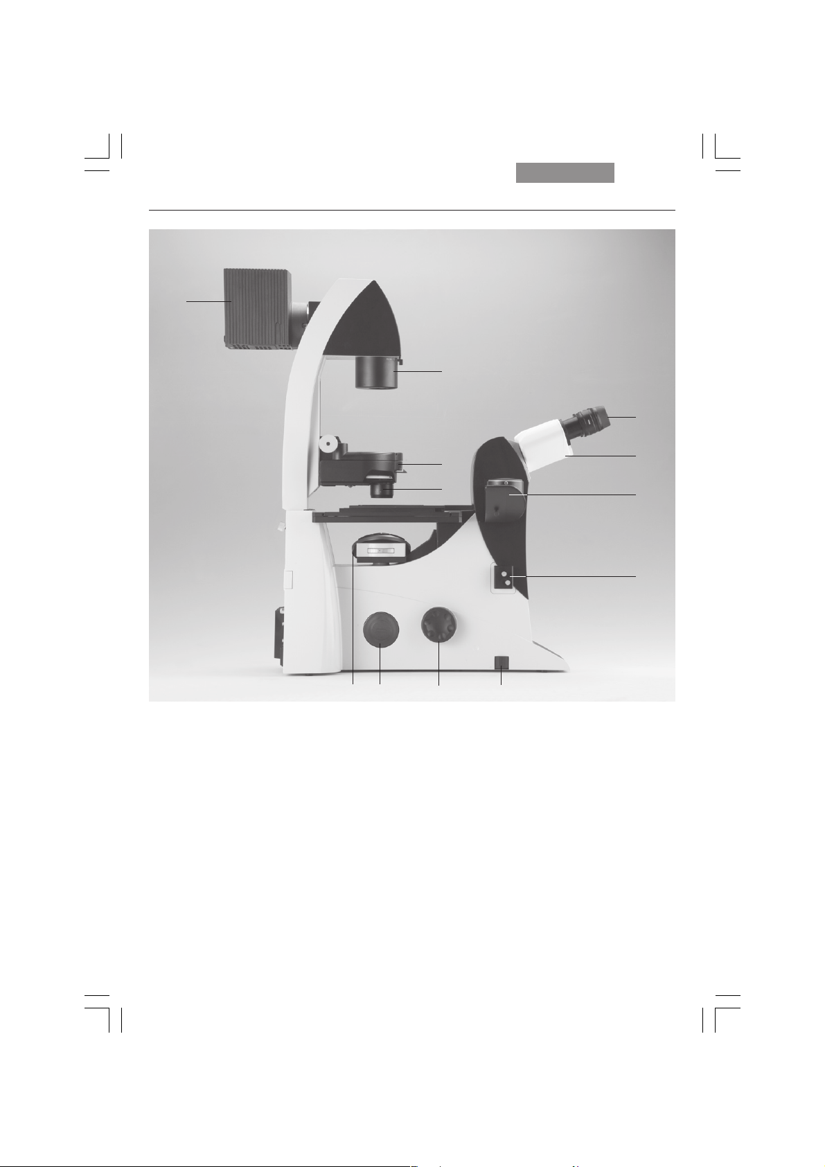
19
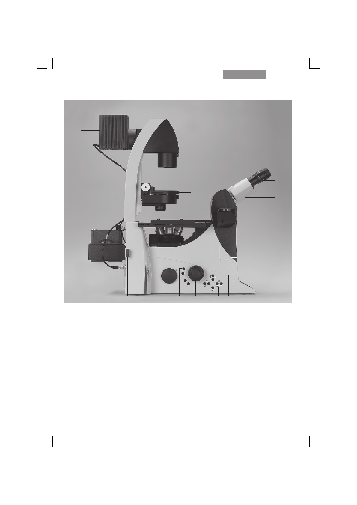
Fig. 1 Left side, Leica DMI4000B and DMI6000B
1 Eyepiece
2 Eyepiece tube
3 Top port
4 Intermediate pupil interface
5 LeicaScreen
6 Light intensity
7 Field diaphragm
8 TL/IL switching
9 Aperture diaphragm
10 Focus wheel (motorized Leica DMI6000B,
manual (fine and coarse) Leica DMI4000B)
16
2
15
3
4
5
678910111213
11 Variable function buttons
12 Left side port
13 Booster lens (fluorescence microscopes only)
14 Lamp mount (fluorescence microscopes only)
15 Condenser head
16 Condenser base
17 Field diaphragm
18 Transmitted-light lamp housing
19 DIC objective prism disk
18
Page 19
4. Overview of the Instrument
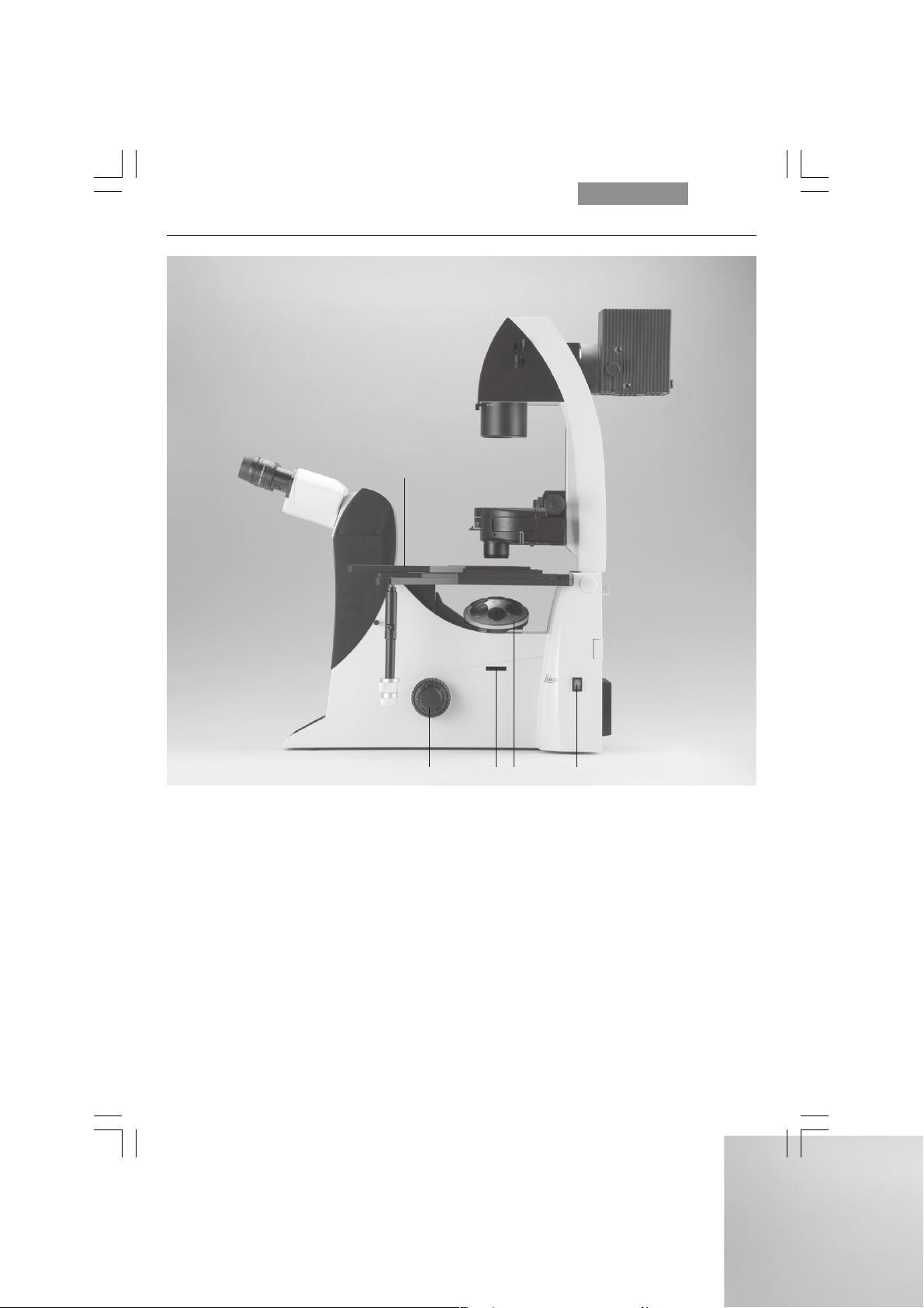
11
4
5
12 3
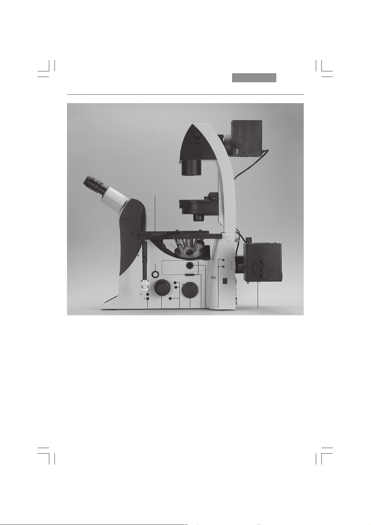
Fig. 2 R
1 E-Focus buttons (Leica DMI6000B only)
2 Focus wheel (motorized Leica DMI6000B,
3 Variable function buttons
4 Opener for drawer (fluorescence microscopes only)
5 Drawer (fluorescence microscopes only)
6 Right side port
ight side Leica DMI4000B and DMI6000 B
manual (fine) Leica DMI4000B)
67812910
7 Analyzer slot
8 Centering window (fluorescence microscopes only)
9 Field diaphragm centering
(fluorescence microscopes only)
10
Incident-light lamp housing (fluorescence microscopes
only)
11 Objective turret
12 Stage with attachable mechanical stage
19
Page 20
4. Overview of the Instrument
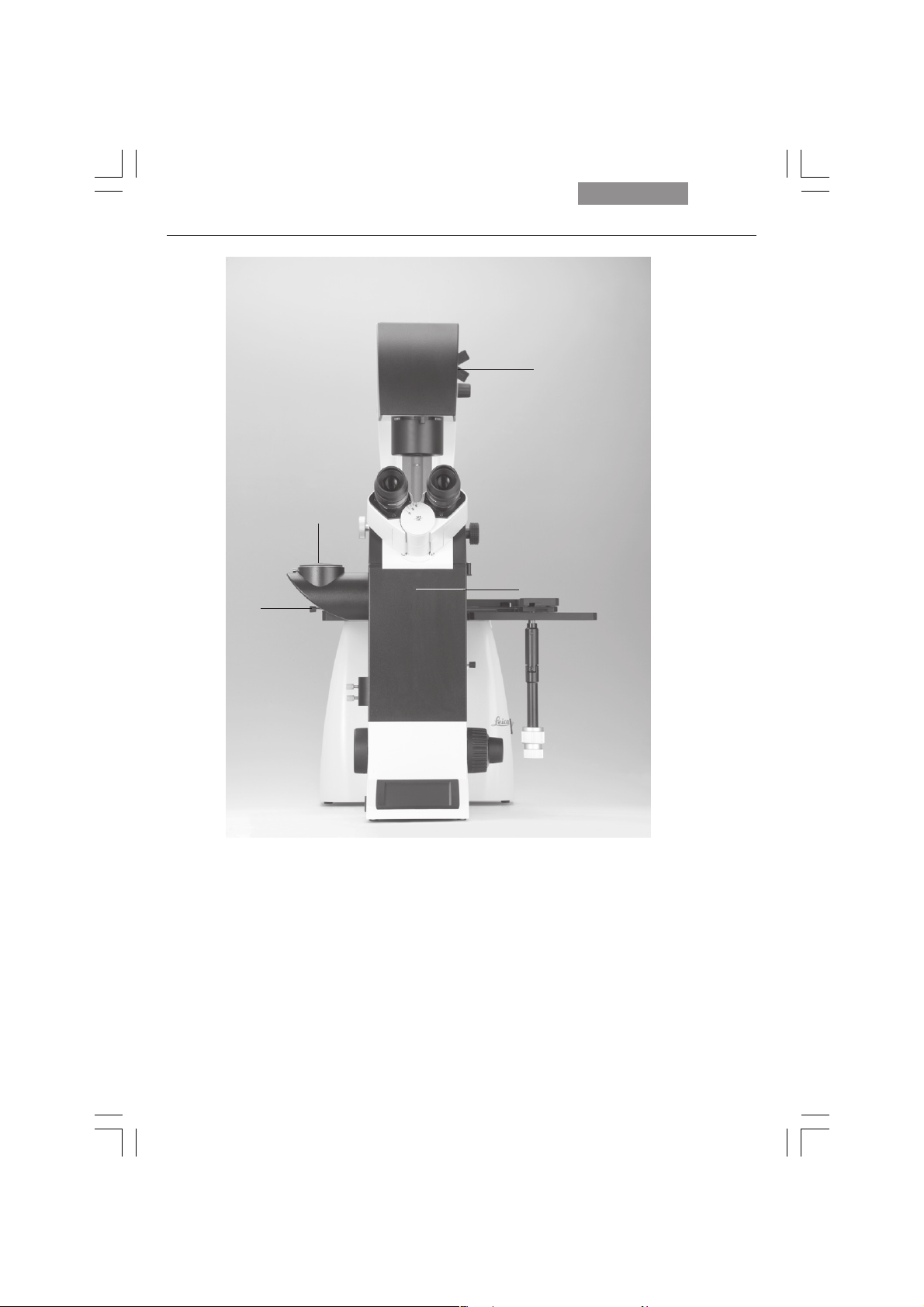
4
3
5
6
2
1
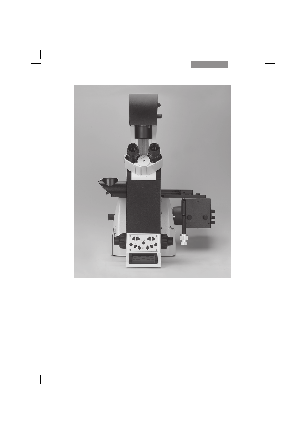
Fig. 3 Front view Leica DMI4000B and Leica DMI6000B
1 LeicaScreen
2 Front control panel
3 Port switching
4 Top port
5 Manual transmitted-light filters
6 Bertrand lens centering
20
Page 21
4. Overview of the Instrument
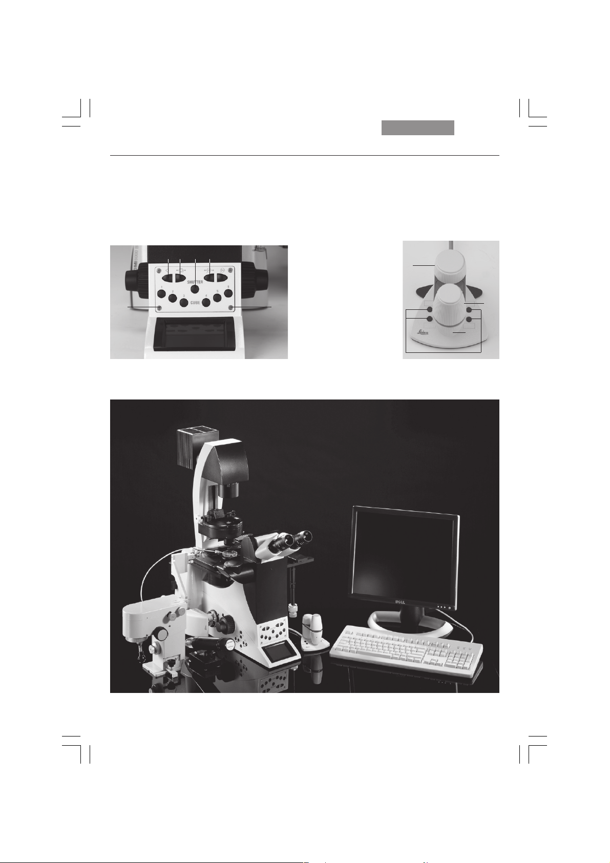
Fig. 3a Front control panel
1 Fluorescence cube
2 Shutter
3 100% light to all eyepieces
4 Port selection
5 Magnification selection
6 1x tube lens
2
543
Fig. 3b SmartMove remote control module
1 travel in x
2 Travel in y
3 Focus
4 Variable function buttons
(preassigned at factory)
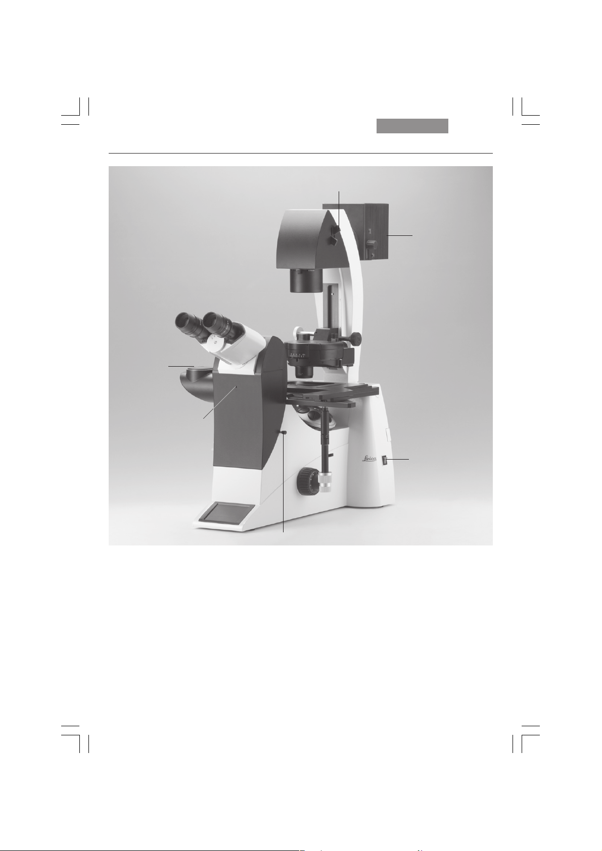
3
11
Fig. 4 General view Leica DMI4000B and Leica DMI6000B with SmartMove remote control module
1
2
4
21
Page 22
4. Overview of the Instrument
12
11
1
Fig. 5 Leica DMI3000 B left view
1 Eyepiece
2 Eyepiece tube
3 Top port
4 Intermediate pupil interface
5 Light intensity
6 Focus wheel
7 Left side port
8 DIC objective prism disk
9 Condenser head
10 Condenser base
11 Field diaphragm
12 Transmitted-light lamp housing
10
9
8
567
2
3
4
22
Page 23
4. Overview of the Instrument
5
Fig. 6
Leica DMI3000 B right view
1 Focus wheel
2 Analyzer slot
3 Objective turret
4 On/Off switch
5 Stage with attachable mechanical stage
1
2
34
23
Page 24
4. Overview of the Instrument
2
1
3
4
Fig. 6 Leica DMI3000 B front view
1 Port switching + Bertrand lens
2 Top port
3 Manual transmitted-light filters
4 Bertrand lens centering
24
Page 25
4. Overview of the Instrument
4
5
3
2
Fig. 6b Leica DMI3000B
1 Manual magnification changer
2 Bertrand lens centering
3 Top port
4 Manual transmitted-light filters
5 Interchangeable transmitted-light lamp housing
6 On/Off switch
6
1
25
Page 26

5. Unpacking the Microscope
5. Unpacking the Microscope
The microscope is delivered in several packages.
The stand package contains the following components:
• Stand with integrated incident-light axis,
objective turret and tube
• Illumination arm
• Specimen stage
• CD with Leica Application Suite (LAS) software package
• Instructions and list of microscope presets
(identification sheet)
The system package contains the microscope's
accessories:
• Eyepieces
• Objectives
• Condenser
• Lamp housings with accessories
• Assembly tools
• Additional accessories such as filter cubes,
etc. depending on feature set
The Leica CTRxxxx electronics box, the
SmartMove remote control module,
stages, stage accessories
100 supply unit are provided in separate packages.
and the external ebq
movable
26
Page 27
Please carefully compare the contents of the delivery to the packing slip, delivery note or invoice. We urgently recommend storing a copy of
these documents with the manual to ensure that
you have information on the time and scope of
delivery handy for subsequent orders or service
work. Please ensure that no small parts remain
in the packing material. Parts of our packing material are marked by symbols to simplify recycling.
First, carefully remove all components from the
transportation and packaging materials.
Caution!
Do not put the instrument into operation in
the event of visible damage to the components or packing material.
5. Unpacking the Microscope
Caution!
Do not connect the microscope or peripherals to an AC power source at this time
under any circumstances!
Installation location
Work with the microscope should be performed
in a dust-free room, which is free of oil vapors
and other chemical vapors, as well as extreme
humidity. At the workplace, large temperature
fluctuations, direct sunlight and vibrations
should be avoided. These may adversely affect
measurements and long-term observations.
Allowable ambient conditions
Temperature 15–35°C
Relative humidity maximum 80% up to 30°C
Note:
If at all possible, avoid touching the lens surfaces of the objectives. If fingerprints do appear
on the glass surfaces, remove them with a soft
leather or linen cloth. Even small traces of finger
perspiration can damage the surfaces in a short
time. See the chapter “Care of the Microscope”
p. 107, for additional instructions.
→
Microscopes in warm and warm-damp climatic
zones require special care in order to prevent
the build up of fungus.
See the chapter “Care of the Microscope”
→
p. 107, for additional instructions.
Electrical components must be placed at
least 10 cm from the wall and away from
flammable substances.
Caution!
27
Page 28

5. Unpacking the Microscope
Transport
For shipping or transporting the microscope
and its accessory components, the original
packaging should be used.
As a precaution to prevent damage from vibrations, the following components should be disassembled and packaged separately:
• Unscrew the objectives.
• Remove the eyepieces.
• Remove the condenser.
• Remove the specimen stage.
• Remove the transmitted-light arm.
• Remove the lamp housings.
• Remove the lamp housing mount.
• Disassemble the burner of 106 z lamp housing.
• Remove the filter cube.
• Remove all moving or loose parts.
28
Page 29

6. Assembling the Microscope
6. Assembly
The microscope components* are logically assembled in this order:
•Transmitted-light illumination carrier
• DIC module and DIC objective prisms
• Condenser with condenser head
• Eyepieces
• Objectives
•Transmitted-light lamps
• Lamp housing mount (mirror housings)
• Incident-light lamps
• Assembly of incident light turret disk
• Specimen stage
• Polarizer and analyzer
The order may be vary when using
climate
chambers or other systems and optical accessories.
In this case, read Chapter
“6.16 Optional accessories” → p. 56.
6.1 Assembly Tools
If possible, the microscope should be assembled and set up with the assistance of Leica
sales or service personnel.
A small number of universal screwdrivers which
are included in the scope of delivery are required for assembly (Fig. 7).
Fig. 7 Assembly tools
1 Phillips screwdriver*
2
3 mm Allen key
3 1.5 mm centering key*
4 2 mm centering key*
5 3 mm hex key*
6 2.5 mm hex key* (short type)
7 2.5 mm hex key*
* depending on scope of delivery
2
5
1
3
4
6
2
7
29
Page 30
6. Assembly
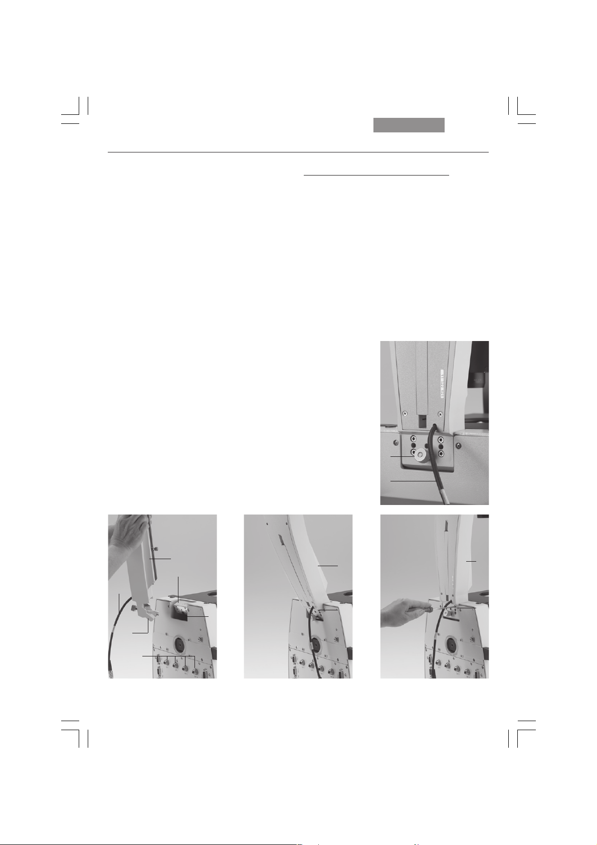
6.2 Installation of the
transmitted-light illumination carrier (DL)
Wipe the installation surface on the microscope
(8.3) with a dry cloth. Tip the illumination carrier
(8.1) back slightly and install it so that the pin
(8.2) engages the groove in the support surface
(8.4).
Set the DL illumination carrier upright and fasten
it with the 4 screws.
When fastening the transmitted-light illumination carrier, do not hold it so as to ensure its optimal alignment with the optical axis.
The tilt angle of the illumination carrier can be
varied with the knurled screw (9.1) or fixed vertically.
Fig. 8 Installing the transmitted-light illumination carrier
1 Transmitted-light illumination carrier
2 Transmitted-light illumination carrier pin
3 Support surface
4 Support surface groove
5 Support surface groove
6 EXT1-EXT4 sockets
7 Electronics cable
Leica DMI4000B and Leica DMI6000B
Connect the electronics cable to one of the
sockets, EXT1 - EXT4.
The transmitted-light lamp housing for 12 V
100 W halogen lamps is a separate component.
For instructions on replacing the halogen lamp
Ch. 6.10, p. 45.
→
Fig. 9 Transmitted-light illumination carrier, rear side
1 Knurled locking knob
of the transmitted-light illumination carrier
2 Connector cable for the electronics box
1
2
30
1
3
7
4
2
6
1
5
1
5
Page 31

6. Assembly
6.3 Installation of the DIC Module
and DIC Objective Prisms
If your microscope is not equipped with DIC,
please continue with Chapter 6.4.
In the Leica DMI series microscopes, the DIC
prisms are already installed in the DIC disk below the objective turret (Fig. 10b).
Motorized,
manual coded and manual DIC disks are available. The installation is identical for all types.
Proceed as follows when making changes to the IC
prism disk:
• Remove the front cover (Fig. 11) below the ob-
jective revolver after releasing the socket
screws (Fig. 10a).
Fig. 10a Removing the front cover
Fig. 11 Front cover, DIC prism disk
• Insert the DIC prism disk (Fig. 10b) squarely in
its receptacle. First, lightly tighten one screw
with the included 3mm hex screwdriver, then
tighten both Allen screws.
Note: insert the prism disk with the electronics board facing down.
Do not touch the electronics (especially the contacts) with your
bare fingers!
Replacing individual IC prisms:
• Release the two socket screws and remove
the prism disk.
• Place the prism against the stop pin (10b.3),
place the washer between the screw and the
prism, and tighten gently to prevent undue
tension. Insert the prism so that its identifying
letter, e.g. ID, is facing upward and is legible.
• After installing the prisms, replace the prism
disk in its receptacle.
Fig. 10b DIC objective prism turret (coded and motorized)
1 IC objective prism in frame
2 Identification letter (ID)
3 Orientation pin
Fig. 12 IC objective prism
1 Objective prism in frame
2 Screw and washer
1
2
321
31
Page 32

6. Assembly
6.4 Installation of Specimen Stages
A wide range of specimen stages are available.
The most important are the following:
• Fixed stage (248 mm x 204 mm) (Fig. 13):
normal, heating and temperature-controlled,
with and without attachable mechanical
stage
• Fixed micromanipulation stage (248 mm x 204/
112 mm) (Fig. 15): normal, heating and temperature-controlled, with and without attachable mechanical stage
• Standard manual (Fig. 14) and motorized
3-plate cross-stage, positioning range: 83 mm
x 127 mm
• Manual (Fig. 15) and motorized micromanipulation 3-plate cross-stage
positioning range: 40 mm x 40 mm
• manual rotating stage
• scanning stage IM 120 x 100
(motors on bottom)
Fig. 14 Mechanical 3-plate stage
Fig. 15 Micromanipulation stage with attachable
mechanical stage
Fig. 13 Fixed stage (normal)
32
Fig. 16 3-plate micromanipulation stage
Page 33

6. Assembly
The assembly of these stages is identical. The
stages are solidly attached to the microscope by
three screws. In the case of fixed stages, an attachable mechanical stage may be installed
(Fig. 18). These are supplied in a separate package.
Multiple-plate stages are supplied separately.
Like the fixed stages, these stages are mounted
as follows:
• If the screws for the stage are already in the
stand, remove them first. In most cases, the
screws will be found in the packing material
of the stand.
Caution!
!
The screw lengths may vary. When using
screws of different lengths, use the shorter of
the three screws in the front hole and the
equally long ones in the rear holes.
• Use a clean cloth to remove dust and packing
material residue from the stand’s contact surface for the stage.
• Align the stage so that the pair of holes faces
back toward the illumination axis and the single hole faces forward toward the tube.
• Align the mounting holes in the stage with the
holes in the support surface. If the holes are
covered in the case of 3-plate cross-stages or
scanning stages, please shift the upper stage
plate until the opening becomes visible.
• First, tighten the single front screw with the
included 3 mm hex screwdriver. Be sure to
use the
front hole, as an excessively long screw can
interfere with the focus travel. (If you have a
rotating stage, please continue reading under
“Rotating Stage and Insert Frame for
Coverslips”).
shortest of the three screws in the
Fig. 17 Fixed micromanipulation stage
Fig. 18 Attachable mechanical stage for fixed
micromanipulation stage
33
Page 34

6. Assembly
• Next, firmly tighten the two rear screws.
• Finally, give the front screw a final firm tightening.
Fixed stage
Attachable mechanical stages designed to accept a variety of culture dishes are also available for fixed stages. (Fig. 18).
Two screws are included with the attachable
mechanical stage. Tighten these screws in the
threaded holes on the underside of the fixed
stage with the 3mm hex screwdriver. Retighten
these screws from time to time after frequent
use.
The attachable mechanical stage has been
preadjusted in the factory. In the event that the
attachable mechanical stage runs out of focus
when moving from right to left, this can be corrected by Leica’s technical service.
Next, remove one or more of the ordered insert
frames (Fig. 20) from their packaging and place the
insert frame into the precise retention system. The
stage, the attachable mechanical stage and the insert frame are now ready for use.
Some (not all) inserts are provided with self-adhesive scales to permit the coordinates to be
read.
Apply these scales to the recesses of the attachable mechanical stage.
Fig. 20 a, b, c
Inserts for attachable mechanical stage (micromanipulation
stage)
a
Fig. 19 a, b Inserts for attachable mechanical stage
(fixed stage)
34
a
b
b
c
Page 35

Manual fixed micromanipulation stage
To install the attachable mechanical stage for
the manual fixed micromanipulation stage
(Fig. 24), proceed as you would for the attachable mechanical stage of the standard stage.
The insert frames (Fig. 20a to c) differ at this
point. These are held by two screws on the attachable mechanical stage and changed by releasing the screws.
Fig. 21
Inserts for fixed stages
6. Assembly
Fig. 24 Installation of attachable mechanical stage
Fig. 25 Installation of attachable mechanical stage
Fig. 22
Glass insert for
3-plate cross-stage
and scanning stage
Fig. 23
Heater insert
35
Page 36

6. Assembly
Motorized 3-plate or scanning stages
3-plate stages and scanning stages: after installing the stage, connect the included stage
cable (for motorized stages) first to the socket
on the stage, then to the CRT6000 or CTR6500
box. The correct place on the box is called
“XY Stage”.
A variety of inserts (including heating ones) are
available for the normal 3-plate and scanning
stages. Install these inserts diagonally from
above into the corner with the spring clips. The
insert will click into place when seated properly.
Caution:
!
Press the spring clip into place only from the
side.
Do not press the insert onto the spring clips diagonally from above, as the insert will not be
aligned parallel to the stage and may be bent in
the process.
36
Page 37

6. Assembly
Rotating Stage and Insert Frames for Coverslips
The rotating stage (Fig. 30) is also mounted with
3 screws (30.2). Rotate the stage to make all of
the threaded holes accessible. Insert the
screws (30.2).
Caution:
!
Use additional washers (30.3) for the rear holes.
Tighten the screws only lightly, as the rotating
stage must be centered first: insert the adjusting
aid into the rotating stage for this purpose. Activate the Bertrand lens and focus, or use a focusing telescope (Fig. 32). Move the stage until
the bright circle is in the middle of the field of
view. Next, tighten the stage, swing the
Bertrand lens out and remove the adjusting aid.
To insert glass slides in insert frames (31.1),
press on the center of the leaf spring (31.2) and
insert the coverslip in the direction of the arrow.
Clamp the insert frame in the attachable mechanical stage (30.1).
Fig. 30 Rotating stage
1 Attachable mechanical stage
2 Screws for stage mounting
3 Washers
2
1
Fig. 31
1 Insert frame for coverslips
2 Leaf springs
3
2
1
2
Fig. 29 a, b Mounting screws for 3-plate cross-stage
ab
Fig. 32 Focusing telescope
37
Page 38

6. Assembly
6.5 Installation of Condensers
All condensers of the Leica DMI series are
equipped with a 7-position turret disk that can
be equipped with light rings phase contrast (PH)
or dark field (DF), IC prisms for transmitted-light
interference contrast (DIC)
or slit illuminators
for integrated modulation contrast (IMC).
Light rings, slit diaphragms and condenser
prisms are generally already installed in the
turret at the factory, making the following
assembly steps unnecessary. Please continue
page 41, Installation of Condensers.
on →
Installing the light rings and slit diaphragms
• Switch the microscope off.
• Remove the condenser cover (38.1). Insert the
light ring in one of the condenser disk’s large
receptacles with guide grooves.
•Turn the right-hand centering screw back fully
with the adjusting key (39.2). To prevent the
condenser disk from turning further, insert
the adjusting key (39.2) into the left-hand
centering screw of the disk. It may protrude a
maximum of 1 mm into the opening.
Insert light rings for Phaco (marked with the ID
numbers 0, 1, 2, 3 and the focal intercept S of the
corresponding condenser head), DF diaphragms
(marked with a D for dark field and the focal intercept S of the corresponding condenser head)
and slit diaphragms (marked M05, M10, M20,
M40 and M63)
in the location holes of the turret
disk as follows:
• Select a position and ensure that the two
mounting screws have been released to the
point that they no longer extend into the position. To adjust the screws, turn the desired
light ring position into the beam path. You can
now turn the screws using the two adjusting
keys.
Fig. 33 Condenser base S1-S28
38
Fig. 34
Condenser head S1
Fig. 35
Condenser head S28
Page 39

• Next, take the special condenser tool
(Fig. 39.1).
!
6. Assembly
Caution:
• If possible, install the light rings 0 to 3 in ascending order. The numbering of the openings
is located at the edge of the crown gear
(4 large openings: 1-4; 3 small openings: 5-7).
• Grasp the light ring to be installed with the
condenser tool (the lettering must face upward and be legible) so that the tab of the light
ring is positioned to the center of the tool’s
cam and the upper edge of the light ring is lying flat in the holder of the tool. The numbers
should be positioned toward the end of the
tool. Press the cheeks of the tool to grasp
the light ring (Fig. 39a).
•Two guide hooks are located on the underside
of the light rings. These must fit into the two
grooves of the opening.
Insert the light ring (holding the condenser
tool angled slightly upward and at a 90° angle
to the housing) so that the mount fits under
the spring clip of the retainer (Fig. 3).
Do not press the spring clip down under any
circumstances. This can destroy the clip or
result in an unstable position of the light ring.
Turn the light ring to ensure that it snaps into
position and release the tool.
Remove fingerprints or dust from the prism
with care.
• Use the left centering screw to roughly center
the light ring. The right centering screw must
not restrict the range of adjustment under any
circumstances.
• Note the number of the opening and the light
ring designation for entry into the Leica Application Suite (LAS).
• Remove the adjusting key and close the condenser.
• Fine adjust with the Bertrand lens or telescope after switching the unit on (Fig. 32).
Fig. 36 Phase rings Fig. 37 Condenser prisms
39
Page 40

6. Assembly
Please continue reading if you also have to install IC prisms. Otherwise, skip to the next section.
Installation of IC prisms
• Switch the microscope off.
• Remove the condenser cover (38.1). Insert the
prism in one of the condenser disk’s large receptacles with guide grooves.
•Turn the right-hand centering screw back fully
with the adjusting key (39.2). To prevent the
condenser disk from turning further, insert
the adjusting key (39.2) into the left-hand
centering screw of the disk. It may protrude a
maximum of 1 mm into the opening.
• Grasp the prism to be installed with the condenser tool (the lettering must face upward
and be legible) so that the tab of the prism ring
is positioned to the center of the tool’s cam
and the upper edge of the prism is lying flat in
the holder of the tool. The numbers K2 to K16
should be positioned toward the end of the
tool. Press the cheeks of the tool to grasp
the prism (Fig. 39a).
•Two guide hooks are located on the underside
of the prisms. These must fit into the two
grooves of the opening.
Insert the prism (holding the condenser tool
angled slightly upward and at a 90° angle to
the housing) so that the mount fits under the
spring clip of the retainer (Fig. 39a).
Fig. 38 Condenser
1 condenser cover, 2 centering opening
1
2
40
Fig. 39 Open condenser
1 condenser tool, 2 adjusting key
1
2
Fig. 39a Inserting the prism
The designation must be visible when
installed and oriented toward the
center of the condenser.
DIC images are not possible otherwise.
1
Page 41

6. Assembly
Caution:
!
Do not press the spring clip down under any
circumstances. This can destroy the clip or
result in an unstable position of the prism.
Turn the prism to ensure that it snaps into position and release the tool.
Remove fingerprints or dust from the prism
with care.
• Use the left centering screw to roughly center
the prism. The right centering screw must not
restrict the range of adjustment under any circumstances.
• Note the number of the opening and the prism
designation for entry into the Leica Application Suite (LAS).
• Remove the adjusting key and close the condenser.
• Fine adjust with the Bertrand lens or telescope after switching the unit on (Fig. 32).
Installation of Condensers
The installation procedure is identical for all
condensers S1 to S70 (motorized or manual/
coded).
Release the socket head screw at the right side
of the condenser holder. Place the condenser on
the retaining pins of the illumination arm and
move the condenser to the correct height. Use
the markings on the column and condenser to
determine the correct position.
Once you have reached the correct position,
tighten the socket head screw.
Fig. 40 Installation of condenser on
transmitted-light illumination arm
41
Page 42

6. Assembly
Condenser heads
Four different condenser heads are available:
1) S1/1.40 oil
2) S1/0.90 dry
3) S23/0.53
4) S28/0.55
Condenser heads 3 and 4 are screwed directly
into the condenser body. A spacer ring (42.2)
must be screwed into the thread at the bottom of
the condenser body prior to installing condenser
heads 1 and 2. The S1 condenser heads fit into
this ring.
The S70 condenser is delivered complete with a
condenser head, making additional assembly
unnecessary.
Fig. 41 Condenser on transmitted-light illumination arm
Fig. 42 Installation of condenser heads S1
1 Condenser base
2 Spacer ring
3 Condenser head
42
Fig. 43 Installation of condenser head S28
1
2
3
Page 43

6. Assembly
6.6 Installation of eyepieces
The eyepieces are inserted into the eyepiece
tubes.
Note:
We recommend running a teach-in via the Leica
Application Suite (LAS) software when using
eyepieces not included in the scope of delivery.
This will ensure that the total magnification
shown in the LeicaScreen is correct.
Fig. 44 Eyepieces
6.7 Installation of objectives
The positions in the objective turret disk are
numbered (Fig. 45). Depending on your equipment, the individual objectives have already
been assigned to specific positions at the factory.
For details on the exact positions of the objectives, please refer to the enclosed identification sheet.
!
Caution:
Close vacant threads in the nosepiece with dust
protection caps!
Please note that the front lenses of the objectives point upward and are therefore more vulnerable to contamination than those of upright
microscopes.
Check the front lenses for cleanliness frequently.
Note:
Leica DMI6000B:
We recommend running a parfocality compensation via the Leica Application Suite (LAS) software.
Fig. 45a Objective turret Fig. 45b Objective turret, loaded
43
Page 44

6. Assembly
6.8 Installation of filters in the illumination arm
The Leica DMI series is equipped with a filter
magazine to accommodate two 40 mm dia. filters
as a standard feature. The filters are installed at
the factory. To change filters yourself, proceed
as follows:
• Release the screw (46.1) and remove the cover.
• Place the filter in the holder.
• Place the cover on transmitted-light illumination
carrier and fasten with the locking screw.
Leica DMI6000B:
• Activate the filters via the Leica Application Suite
(LAS).
Leica DMI3000B and Leica DMI4000B:
• Mark the 2 levers with the provided adhesive labels.
Fig. 46 Unscrewing the filter holder cover and inserting
filters in the transmitted-light illumination arm
1 Screw
1
6.9 Installing the transmitted-light lamp
housing
• Place the lamp housing in the transmitted light
lamp housing mount (Fig. 47) and fasten it with
the clamping screw on the side.
• Thread the cable through the transmitted-light
illumination arm (Fig. 48).
• Connect the lamp housing cable to the power
supply for transmitted light on the Leica
CTRxxxx electronics box (Fig. 49.1).
Leica DMI3000B:
• For the DMI3000B, connect the cable directly
to the back of the microscope.
For instructions on changing the lamp, please
see Chapter 6.10.
These instructions also apply to installing an Hg
lamp on the transmitted-light axis. For descriptions of the lamp housings and replacement of
the burner, please see Chapter 6.12, →
Fig. 47 Mounting the lamp housing on the
transmitted-light illumination arm
p. 48ff.
Fig. 48 Lamp housing cabling (cable duct)
44
Fig. 49 Connecting the lamp housing to the
Leica CTR6000 electronics box
1
Page 45

6. Assembly
6.10 Installation and replacement of the
transmitted-light lamps: 107 or 107/2 lamp
housing
This lamp housing is used with a 12V 100W halogen lamp, which is already mounted.
In case the lamp has to be removed:
Changing the 12 V 100 W halogen lamp
Caution!
Ensure that the lamp housing has been disconnected from the power supply. Unplug
the power plug and the power supply during
assembly.
Caution!
Light sources pose a potential irradiation
risk (glare, UV-radiation, IR-radiation).
Therefore, lamps have to be operated in
closed housings.
• Lift the housing off (Fig. 50b).
• Remove the lamp.
Caution!
Do not remove the new lamp’s dust cover
until you have installed the lamp. Avoid fingerprints on the lamp.
• Insert the new 12 V 100 W lamp (Fig. 51) with
the dust cover straight into the socket until it
stops. Be sure that the lamp is inserted
straight.
• Remove the lamp’s dust cover.
• Replace the housing and fasten it in place using the fastening screw.
Fig. 50b
Removing housing
• Remove the fastener screw on the housing
(Fig. 50a).
Fig. 50a
Lamp housing 107/2
Releasing the
fastening screw
Fig. 50c
Lamp housing 107/2
opened
1 Mount with
halogen lamp
2 Collector
1
2
45
Page 46

6. Assembly
Fig. 51
Inserting
lamp with
cover
a right
b wrong
6.11 Installing the lamp housing mount and
mirror housing (Leica DMI4000B and
DMI6000B)
Place lamp housing mount (Fig. 53) or mirror
housing on rear wall. Mount from front with
socket head screws.
a
b
Fig. 53 Lamp housing mount
Next, attach the appropriate connector(s) (right,
left, straight) to the lamp housing mount. The
lamp housing or coupling is then mounted on the
connector, which is also held by four screws.
Fig. 52 Rear view, Leica DMI4000 B and DMI6000B
1 Installation point for lamp housing mount
or mirror housing
2 Holes for lamp housing mount or mirror housing screws
2 2
1
46
Fig. 54 Lamp housing 106z
1 Collector adjustment
2 Vertical lamp adjustment
3 Horizontal lamp adjustment
4 Adapter ring
4
2
3
1
Page 47

If a booster lens is included in the scope of delivery, insert it into the rear stand opening at the
left or right, depending on the stand model.
The booster slide has several positions:
1. Slide pulled out:
no effect
2. Depending on orientation of slide:
a) symbol visible:
•
center orientation
The intensity of the fluorescence is
increased by 50% in the center of
the field of view (approx. 30% of the
field).
b) symbol
visible:
The overall intensity is reduced by
25%. The entire field of view is evenly
illuminated, however.
6. Assembly
Fig. 56 Booster lens in stand
1 Booster lens
1
Fig. 55 Booster lens
Fig. 57 Hg-mercury burner
47
Page 48

6. Assembly
6.12 Installation and replacement of
incident-light lamps
Caution!
Leica DMI4000B and Leica DMI6000B:
Light sources pose a potential irradiation
risk (glare, UV-radiation, IR-radiation).
Therefore, lamps have to be operated in
closed housings.
Ensure that the lamp housing has been disconnected from the power supply. Unplug
the power plug and the power supply during
assembly.
During assembly work on xenon burners, always wear the supplied protective gloves
and face protection (Fig. 58) (risk of explosion).
Never touch the glass parts of the burner
with bare hands.
Never look directly into the beam path
(blinding hazard).
Fig. 58
Protective gloves and mask
Lamp housing 106 z
This lamp housing is suitable for use with a 12 V
100 W halogen lamp or a variety of gas discharge
lamps.
Caution!
Make sure to follow the instructions and
safety notes of the lamp supplier.
Before changing lamps allow at least 30
mins for cooling down!
Fig. 59 Lamp housing 106 z L with Hg 100 W lamp
1 Collector focusing
2 Vertical lamp adjustment
3 Horizontal lamp adjustment
4 Hg lamp mount
5 Reflector adjustment (not visible)
48
3
1
4
Page 49

6. Assembly
Inserting gas discharge lamps (Hg and Xe) in
the 106z lamp housing
Hg and Xe lamps are powered by separate supply units.
Please also read the separate instruction
manual provided with these supply units.
The following gas discharge lamps may be
used and require different supply units and
lamp mounts (Fig. 60, 61):
Type Typical bulb life*
100W high-pressure mercury burner (direct current) 200 hrs.
100W high-pressure mercury burner (direct current, type 103 W/2) 300 hrs.
75W high-pressure xenon burner (direct current) 400 hrs.
* Please observe the data sheets of the lamp manufacturer.
Fig. 60 Lamp mounts for Hg 100 gas discharge lamp
1 Uper clamping system
2 Lower clamping system
3 Cooling element
Hg 100
3
1
2
Fig. 61 Lamp mounts for gas discharge lamp Xe 75
1 Upper clamping system
2 Lower clamping system
3 Cooling element
4 Protective cover of Xe 75 burner
a
Xe 75
1
2
b
3
4
49
Page 50

6. Assembly
Caution!
Make sure to follow the safety notes on
page 48.
•To open the 106 z lamp housing, unscrew the
fastening screws on the cover l. Loosen the
contact plug somewhat and pull it out of the
socket (63.9). Flip the cover up (63.1).
• Loosen the mounting screws (63.8) on the
lamp socket and pull the socket out.
• Remove the transport anchorage (red plastic
rod in place of the burner) in the lamp mount.
To do so, remove the lower clamp (60.1, 61.1).
Pull up the cooling element (61.3, 60.3) and
turn it to the side. Detach the lower clamp
system (61.2, 60.2) and remove the transport
anchorage.
Caution!
Do not remove the burner’s dust cover until you
have installed the lamp. Avoid fingerprints on
the lamp. Sweat from your fingers on the glass
will shorten the life of the lamp significantly.
• Install the burner in reverse order.
Caution!
Xe 75 burner:
Remove the burner’s dust cover (61.4) after
you have installed the burner.
Fig. 63 106 z lamp housing (on the side, open)
1 Cover raised
2 Collector
3 12V 100W lamp or
gas discharge lamp in mount
4 Reflector (mirror)
5, 6, 7 Adjusting screw for x-y reflector
8 Locking screws for lamp mount
9 Socket for contact plug
Fig. 62 Rear panel of ebq 100 supply unit
1 Lamp connection
1
50
1
2
4
5
3
6
7
898
Page 51

• Insert the lamp mount, with the burner in-
stalled, into the lamp housing and tighten it
with the screws (63.8).
•Test the adjustment of the collector (63.2):
Do not touch the power supply while performing these actions. When closing the lamp
housing, ensure that the pins of the contact
plug engage in their sockets (63.9).
Tighten the screws of the cover and press the
contact plug home.
• Place the lamp housing in the incident light
lamp housing mount (Fig. 53) and fasten it with
the clamping screw on the side.
• Connect the lamp housing to the external
power supply (62.1).
6. Assembly
Caution!
The burner must be adjusted immediately after lighting.
51
Page 52

6. Assembly
6.13 Equipping the Incident Light Turret Disc
!
Caution:
Please read this section completely before beginning with the assembly of the turret disk.
Leica DMI4000B and Leica DMI6000B:
The fluorescence drawer is located on the right
side of the stand. Before opening this drawer,
remove the cap below the drawer covering the
analyzer slot (66.1). Remove the analyzer if it is
already in the slot.
The replacement of individual cubes is more
convenient with the microscope switched on.
The position to be changed then automatically
turns to the outside and you can be sure that the
cube is positioned in the correct holder. You can
therefore postpone installing the filter cubes until after the microscope has been switched on.
You can also insert the filter cubes while the instrument is switched off.
Press the white button next to the drawer. The
drawer will glide out into its initial position.
The inner disk can only be turned to accept the
fluo cubes in this position.
Fig. 66 Opening the fluorescence drawer
1 Analyzer slot
1
Fig. 67 Open fluorescence drawer
Fig. 64 Filter cube,
front side
52
Fig. 68 Inserting or removing a filter cube
Fig. 65 Filter cube,
back side
Page 53

6. Assembly
The positions in the turret disk are numbered.
Depending on your equipment, the individual filter and reflector cubes have already been assigned to specific positions at the factory. For
details, check the identification sheet included
with your order.
Now open the drawer several mm further until it
clicks into its end position. The disk will no
longer turn in this position.
You can now insert a filter block. Proceed as follows:
•With the holder facing you squarely, insert the
filter or reflector cubes into the holder in accordance with the included identification
sheet.
• The fluorescence cubes are suitable for both
upright and inverted microscopes. When using them with inverted microscopes, insert
them so that the writing is upside down along
the lower edge.
To do so, place the filter or reflector cube on
the left side and press it to the right into the
mounting (Fig. 68).
• For the next cube, close the drawer to the
point that the disk is once again free to turn.
Once you have reached the next position,
open the drawer fully once again. Continue in
this way for all of the cubes.
• Once all filter and reflector cubes have been
inserted, close the drawer and replace the
analyzer or cap.
Replacing cubes with the instrument switched
on:
• Remove the analyzer or the cap of the
analyzer slot.
• Press and hold the Shutter button on the front
panel and press the button of the cube you
would like to insert or replace
time.
• The filter changer will then rotate to the correct position to insert or replace the cube
when you open the drawer by pressing the
white button on the right side of the stand.
The following message will appear in the top
line of the LeicaScreen.
at the same
• Ensure that the cube is correctly seated. A
loose cube can block the disk or be destroyed
by the turning disk.
Load.
To insert the cubes, proceed exactly as described above.
53
Page 54

6. Assembly
6.14 Inserting the Front Module Slider
If your microscope is prepared for integrated
modulation contrast or integrated phase contrast, a front module (possibly in conjunction
with a manual magnification changer) will be integrated in the stand. This is recognizable by a
2x 3 cm opening at the left front side of the microscope. If this opening is not present or
closed, then your microscope is not prepared
for the integrated processes.
A slider for integrated modulation contrast or integrated phase contrast fits in this opening. The
phase contrast slider may still require the installation of phase rings.
Insert the slider with the markings facing forward. It features a bright-field position and two
positions for contrast methods (position A and
position C).
(A and C designate the eyepoint of the used objective. Please refer to the included objective
list for the eyepoint of your objective. It can also
be found engraved on the objective.)
6.15 Installation of the polarizer and analyzer
Installed at the factory.
To change the components, proceed as follows:
Motorized condenser:
See included installation instructions.
Manual condenser:
Attach the single or triple position holder to the
top of the manual condenser. The holder has a
guide that must be inserted in the opening next
to the screw threads. The holder must be positioned so that the polarizer or filter to be used
covers the opening of the condenser.
Insert the polarizer or filter with the correct side
facing up into the holder (λ: lambda and
polarizer; POL: polarizer only). A click mechanism will indicate proper seating. The polarizer
must turn easily between the two stops (approx.
30°).
Fig. 70 Mechanical polarizer holder
1 Manual polarizer
2 Manual analyzer
1
54
Fig. 71 Condenser with motorized polarizer
2
Page 55

Analyzer for incident light and transmitted light.
• Remove the cap (Fig. 72) on the right side of
the stand (under the fluorescence drawer).
• Insert the analyzer into the receptacle until it
latches in place (Fig. 73.1).
Fig. 72 Analyzer slot cap
6. Assembly
Fig. 73 Inserting the analyzer
1 Slot
2 Analyzer
Fig. 74 Inserting the analyzer
1
2
55
Page 56

6. Assembly
Fig. 75 C-mount 0.63x
6.16 Optional Accessories
Camera
Connecting a camera
A camera can be installed using a C-mount or
Vario mount.
• Place the C-mount or Vario mount onto one of
the camera ports and secure it with the locking screw at the side.
• Screw on the camera.
Note:
When using a C-mount or Vario mount, run a
teach-in via the Leica Application Suite (LAS)
software.
Connecting multiple cameras
Two or more cameras – for example a digital and
an analog camera – can be adapted as required.
Fig. 76 C-mount 0.5x
56
• When using a DC type camera, connect the
camera to the PCI card of your PC.
• When using a DFC type camera, connect the
camera to the FireWire card of your PC.
Note:
Please read the separate operating manual of
your digital camera.
Page 57

6. Assembly
6.17 Connection to the Electronics Box
CTR4000, CTR6000 or CTR6500
The Leica DMI 3000 B is supplied without an
electronics box. The power supply is integrated
in the stand and a socket has been provided on
the back of the microscope to connect the
transmitted-light illumination. The illuminated
ON/OFF switch is located on the stand.
Fig. 77 Rear view of CTR6000
1 AC power socket
2 XY Stage socket for motorized stage
3 Direct interface socket optional
4Z Control for separate focus control
5 XYZ Control for SmartMove
6 Microscope socket for microscope
7
12 V, max 100 W for the lamp power cable of stand
8 DL: reset button
CTR 4000 electronics box
The Leica DMI 4000 B is supplied with the
CTR4000 electronics box. The power supply for
the microscope is located in this box. Two sockets are located on the back of the CTR4000 electronics box for 12V/100W transmitted-light and
12V/100W incident-light illuminators. The illuminated ON/OFF switch for the microscope is located on the CTR4000 electronics box.
Fig. 78 Rear view of stand
1 RS232 ports
2 2 x USB
3 4 x EXT.
4 XYZ control for SmartMove
5 Electronic box connection
6 Condenser cable
7 Lamp power cable
8
5
4
3
6
2
7
6
1
1
7
2
5
4
3
57
Page 58

6. Assembly
CTR6000 and CTR6500 electronics box:
Note:
These electronics boxes must not be used with
other stands. The serial number of the associated
stand has been recorded on the back of the electronics box.
A 3-axis control unit for focus and 3-plate cross
stages is integrated in the CTR6000.
A 3-axis control unit for focus and a scanning
stage is integrated in the CTR6500.
• Connect the Microscope (77.6) socket to the
back of the stand (78.5) using the 25-pin microscope cable.
• Connect the SmartMove remote control module
to the XYZ-Control socket (77.5).
• Connect the motorized stage, if present, to the
XY-Stage socket (77.2).
6.18 Connection to the Computer
Note:
To start the Leica Application Suite (LAS), ensure that the COM1 serial port is not in use by
another program or driver. This is frequently the
case when using Palms or other PDAs or when
using external modems or other devices. The
devices in question must therefore always be
disabled before using the Leica Application
Suite (LAS) software.
• Please use the included serial cable. Connect
the COM1 port of your PC with the RS232C
port (78.1) on the back of the stand.
6.19 Connection to the Power Supply
• Once all installation work is complete, connect the electronics box to an AC power outlet
with the included power cable (socket 77.1).
• If you are using the external ebq 100 supply
unit, connect it to an AC power outlet at this
time (socket 79.1).
• Connect the lamp power cable (78.7) to the 12 V,
max 100 W socket (77.7).
Caution!
Ensure that the plugs are correctly inserted
and secured to prevent overheating of the
sockets.
58
Fig. 79 Rear panel of ebq 100 supply unit
1 AC power supply socket
1
Page 59

7. Start-up
7. Start-up
7.1 Functional Principle (Leica DMI4000B and Leica DMI6000B)
Thanks to its intelligent automation, the Leica DMI4000B and DMI6000B can be controlled using a
variety of control elements.
1. Intelligent automation
• Switching between contrast methods at the touch of a button. Light rings, DIC prisms, etc.
are automatically positioned in the beam path.
• The microscope recognizes the selected objective and associated contrast method.
The intensity (INT), aperture diaphragm (AP) and field diaphragm (FD) are always set to
suitable values.
• the INT, AP and FD values are always based on the currently activated illumination axis
(transmitted light or incident light).
• The INT, AP and FD values can be adjusted individually. Manual adjustments overwrite the
previous settings. The current setting is stored and is retained from one session to the next
when power is switched off.
2. Controls
• SmartMove knobs
for stage and focus control
• Fixed function buttons on stand
for INT, AP and FD, as well as for switching between transmitted-light and incident-light
axis
•Variable function buttons on stand and SmartMove
These function buttons have functions suitable to the configuration of your microscope assigned to them at the factory. The functions can be reprogrammed and/or adapted to your
specific requirements, however.
• Complete control of microscope and camera via software
(Leica Application Suite (LAS))
59
Page 60

7. Start-up
Note: (reset function)
The microscope can be reset to its factory default programming:
• With the stand switched off, press the top
three variable function buttons on the left side
of the stand.
• Switch on the power for the stand.
• Hold the buttons until the initialization is complete.
• The standard information display will now appear on the LeicaDisplay.
• Switch the instrument off and back on. The
settings are now saved.
The table on the following page provides an
overview of the microscope functions and their
controls.
60
Page 61

7. Start-up
Function Fixed Variable SmartMove Software
(DMI4000 and DMI6000B) Function Function Function Rotary
buttons buttons buttons knobs
Stand Stand
4000 6000 4000 6000 4000 6000 4000 6000 4000/6000
Select contrast method - - + + + + - - +
Change transmitted light/incident-light axis + + - - - - - - +
Change to objective - - - + - + - - +
Teach-in parfocality - - - - - - - - +
Change operating mode (dry/imm) - - + + + + - - +
Illumination Manager + + + + + + - - +
Magnification changer (motorized) + + - - - - - - +
1)
Focusing - + - - - - - +
Set stops - + - - - - - - +
Go to stop - + - - - - - - +
Change step increment (coarse/fine) - - - + - + - - +
XY stage positioning - - - + +
Change speed - - - - - - - - +
Stage positions (store/go to) - - - - - - - - +
Change to filter/reflector cube + + (+) + + - - +
Side and bottom port (DMI6000 B only) + (+) + - +
DIC fine adjustment + + - - - - - - +
+
+ always possible
(+) optional
- not possible
1)
Focusing alternatively via wheels
61
Page 62

7. Start-up
Possible assignments for variable function buttons on stand and SmartMove
For Leica DMI4000B and Leica DMI6000B:
Function button Function
BF Bright field transmitted light
PH Phase contrast transmitted light
ICT Interference contrast, transmitted light
DF Dark field transmitted light
IMC Integrated modulation contrast
POL Polarization transmitted light
CHANGE TL Cycle through all contrast methods
INT ↑ Increase intensity (transmitted light)
INT ↓ Reduce intensity (transmitted light)
AP ↑ Open aperture diaphragm (transmitted light)
AP ↓ Close aperture diaphragm (transmitted light)
FD ↑ Open field diaphragm (transmitted light)
FD ↓ Close field diaphragm (transmitted light)
SHUTTER TL Open/close TL shutter
TL FLT 1 Enable/disable transmitted-light filter at position 1
TL FLT 2 Enable/disable transmitted-light filter at position 2
FLUO Fluorescence (last filter cube)
CUBE 1-6 Select filter cube in position 1-6
CHANGE CUBE CW Change cube clockwise (1 → 4)
CHANGE CUBE CCW Change cube counterclockwise (4 → 1)
INT FLUO ↑ Increase intensity (fluorescence)
INT FLUO ↓ Reduce intensity (fluorescence)
FD FLUO ↑ Open field diaphragm (fluorescence)
FD FLUO ↓ Close field diaphragm (fluorescence)
CHG FW Toggle filter functions
IFW Activate external filter wheel
ExMan Activate Excitation Manager
SHUTTER FL Open/close fluoshutter
COMBI Combination method (PH fluorescence or ICT fluorescence)
CHANGE COMBI Cycle through all combination methods
CHANGE OBJ CW Cycle through objectives clockwise
CHANGE OBJ CCW Cycle through objectives counterclockwise
Z FINE Activate fine focusing (Leica DMI6000B only)
Z COARSE Activate coarse focusing (Leica DMI6000B only)
XY PRECISE Activate precise stage
XY FAST Activate fast stage
BTP ON/OFF Bottom port on/off (Leica DMI6000 B only)
DRY/IMM Switch dry/immersion
CHANGE FLT Switch TL filter
CHANGE CS Switch to confocal application
OBJ 1-6 Select objective at position 1-6
MEM 1-6 Memory activated stored functions
62
Page 63

7. Start-up
7.2 Switching on the Microscope
Leica DMI3000B:
• Switch on the microscope’s power at the On/
Off switch . The signal lamp is lit when the instrument is ready. (For the Leica DMI3000B
please continue at 7.4. Function Buttons on
the Stand)
Leica DMI4000B and Leica DMI6000B:
• Switch on the power of the electronics box at
the On/Off switch (80.1). The signal lamp (80.2)
is lit green when the unit is ready. All motorized microscope components will then run
through an initialization phase.
Note:
If a PC is connected, switch on the electronics
box first, and then the computer.
After the initialization (Fig. 81) is complete, the
LeicaScreen will display the microscope’s current settings (Fig. 82).
Fig. 80
front side
Leica CTR6000
1 On/Off switch
2 Signal lamp
If a component has not been installed correctly,
the LeicaScreen will display an error message.
See Troubleshooting chapter, → p. 102.
Components such as diaphragms, condensers,
light and phase rings have been pre-centered at
the factory. It may be necessary to correct the
centering after the microscope has been transported and assembled.
Before performing the required steps, please familiarize yourself with the LeicaScreen and the
controls.
Caution!
After turning on the gas discharge lamp, the
burner must be immediately adjusted. Therefore, do not turn on the power supply unit
yet. First, work in transmitted light in order to
familiarize yourself with the microscope’s
controls.
Fig. 81
LeicaScreen
Initialization
Fig. 82
LeicaScreen
after
Initialization
2
1
63
Page 64

7. Start-up
7.3 The LeicaDisplay
(Leica DMI 4000 B and DMI 6000 B)
The screen displays the microscope’s current
settings. The content of the display depends on
the features of the individual microscope.
For information on the abbreviations used, please
turn to the table of abbreviations →
p. 111.
The screen has a number of areas and lines.
Line 1: contrast method
Line 2: objective/magnification
Line 3: illumination/diaphragms
Line 4: active ports
Line 5: focus/stops
(DMI 6000 B only)
The content of the display changes according to
the active function.
Fig. 83 Arrangement of the function buttons – overview
1 Four variable function buttons
2 Illumination Manager
3 Front control panel
4 Focus buttons (DMI6000B only)
5 Three variable function buttons
6 SmartMove knobs
7 SmartMove function buttons
Pictograms
Contrasting method
Objective/
Magnification
Illumination
Diaphragm
Ports/Eyepiece
Focus/stops
(DMI6000B only)
64
6
6
7
543321
7
Page 65

7.4 The Function Buttons on the Stand
7. Start-up
Leica DMI3000B:
• Focus wheels: the left-hand focus wheels can
be used for both coarse and fine focusing; the
right-hand focus wheel for fine focusing only
(a version of the Leica DMI3000B with mirrored focus controls is also available)
• Light intensity: the transmitted-light intensity
can be adjusted continuously from 0 to 12 V
using the potentiometer at the lower left of the
front of the microscope stand.
For the Leica DMI3000B please continue at 7.6.
Illumination.
Leica DMI4000B and Leica DMI6000B:
A number of function buttons are located on
both sides of the stand. These can be broken
down into fixed and variable buttons. The variable function buttons have different functions
depending on the features of the individual microscope.
Fixed function buttons on the left side
The TL/IL button (84.1) toggles between the incident-light and transmitted-light axis. The contrast
method last used with a given axis is restored
when switching.
The INT buttons (84.3) adjust the light intensity.
The adjustment can be made in coarse or fine
steps. Pressing both INT buttons at the same
time toggles between coarse and fine adjustment. “Intensity fine” will appear in the display
when fine adjustment is selected.
The AP buttons (84.2) for the aperture dia-
phragm and FD (84.4) for the field diaphragm
open and close their respective diaphragms.
Note:
Changes to the light intensity as well as aperture
and field diaphragm settings are stored for the
individual objectives and contrast methods.
Fig. 84 Fixed function buttons (left side of stand)
1 Toggle transmitted light/incident light
2 Aperture diaphragm
3 light intensity
4 field diaphragm
3
2
4
1
65
Page 66

7. Start-up
Variable function buttons on the stand
The variable function buttons are assigned functions at the factory that are appropriate to the
features of your microscope. They are labeled
accordingly. For details on button assignments,
please refer to the included identification sheet.
For information on the abbreviations used,
please refer to the list → p. 62.
Note:
The Leica Application Suite (LAS) software is
required for changing the button assignments.
Possible functions*:
BF
PH
ICT
DF
IMC
POL
CHANGE TL
INT ″
INT
AP ″
AP
FD ″
FD
SHUTTER TL
TL FLT 1
TL FLT 2
FLUO
CUBE 1
CUBE 2
CUBE 3
CUBE 4
CUBE 5
CUBE 6
CHANGE CUBE CW
CHANGE CUBE CCW
INT FLUO ↑
INT FLUO ↓
FD FLUO ↑
FD FLUO ↓
CHG FW
IFW
ExMan
COMBI
CHANGE COMBI
CHANGE OBJ CW
(only DMI6000B)
CHANGE OBJ CCW
Z FINE
(only DMI6000B)
Z COARSE
(only DMI6000B)
XY PRECISE
XY FAST
BTP ON/OFF
(only DMI6000B)
DRY/IMM
CHANGE FLT
CHANGE CS
OBJ 1-6
MEM 1-6
(only DMI6000B)
Fig. 85 Function buttons (left side of stand)
1 variable function buttons
2 Open/close aperture diaphragm
3 TL/IL switching
4 Open/close field diaphragm
5 Increase/decrease light intensity
54321
Fig. 86 Function buttons (right side of stand)
1 variable function buttons
* See page 62 for abbreviations
66
1
Page 67

7. Start-up
Function buttons on the front panel (Fig. 87)
100% of the light goes to the eyepiece (87.1).
→
Toggle function for the side ports
→
(87.2). This function depends on the
individual microscope configuration.
Note:
Switching to the bottom port:
via the variable function buttons
(Leica DMI6000B only), switching to
top port: manually.
SHUTTER Opens and closes the shutter (87.3).
→
Switches between the possible mag-
→
nifications of the magnification
changer (87.4).
1x
The magnification changer is set to the
magnification 1x (87.5).
CUBE The CUBE 1 to CUBE 6 (87.6) buttons
permit the direct selection of individual filter cubes, provided the selected cube is valid for the selected
method.
Press the CUBE 3 and CUBE 4 buttons at the same time to display the
assignments of the variable function
buttons. To reset the display, press
the buttons again or wait 3 seconds.
Focus buttons (Fig. 88) (DMI6000B only)
Z″
Z
SET + Z
SET + Z
Moves the Z drive in the indicated direction.
″ Sets the upper focus stop.
Sets the lower stop.
Fig. 87 Front control panel
1 100% light to eyepiece
2 Toggle ports
3 Shutter
4 Switch between subsequent magnifications
5 Subsequent magnification 1x
6 Selecting filter cubes
4
2 5
13
66
Fig. 88
1 Focus control buttons
2 Open filter drawer
2
1
67
Page 68

7. Start-up
SET + Cube buttons 1-6
(Leica DMI4000B and DMI6000B only)
The SET command can be assigned to a function
button of the Leica DMI4000B.
The selected cube is moved to the loading position for replacement. “Load” appears on the
screen. Press the opening button (88.2) to open
the drawer and position the appropriate cube.
The filter cube will remain in this position after
the drawer is closed.
7.5 The SmartMove Remote Control Module
SmartMove knobs
(Leica DMI4000B and Leica DMI6000B)
Use the knobs 89.1 and 89.2 to move the stage in
X and Y directions.
The image is focused using the knob 89.3 (Leica
DMI6000B only).
The height of the knobs can be adjusted to a
comfortable working position by turning 89.4.
Variable function buttons on SmartMove
The variable function buttons are assigned functions at the factory that are appropriate to the
features of your microscope. They are labeled
accordingly. For details on button assignments,
please refer to the included identification sheet.
For information on the abbreviations used,
please refer to the list → p. 62.
7.6 Illumination
7.6.1 Transmitted light
If your microscope has not yet been set up for
Koehler illumination, please continue with the
“Koehler Illumination” section.
Leica DMI3000B:
• Select an objective with moderate magnification
(10x–20x)
.
• Set the condenser to the bright field position.
• Place a specimen on the stage.
• Focus on the specimen using the focus wheels.
• Adjust the light intensity.
• Close the field diaphragm manually until the
edge of the diaphragm appears in the field of
view.
Fig. 89 SmartMove remote control module
1 travel in x
2 Travel in y
3 Focus
4 Individual adjustment of button height
5 Variable function buttons (factory preset)
Note:
The Leica Application Suite (LAS) software is
required for changing the button assignments.
68
1
3
4
2
5
Page 69

7. Start-up
• Using the condenser height adjuster (90.2)
just the condenser until the edge of the field
diaphragm appears in sharp relief (not S70
condenser).
• Open the field diaphragm until
it only just disappears from the field of view
(91d).
Leica DMI4000B and Leica DMI6000B:
• Select an objective with moderate magnification (10x–20x).
• Activate the transmitted-light axis with the
TL/IL button (84.1).
• Press the BF button to activate the bright field
contrast method (one of the variable function
buttons on the stand).
• Place a specimen on the stage.
• Focus the specimen using the SmartMove or
the focus wheels.
, ad-
Note:
The condenser height setting is dependent on
the thickness of the specimen and may require
adjustment for each new specimen.
Koehler illumination
(not for S70 condenser)
Suitable values for the motorized aperture diaphragm and motorized field diaphragm have
been preset for each objective
and Leica DMI6000B).
been centered at the factory.
However, it may be necessary to readjust the
condenser in some cases. Therefore, check the
condenser centering.
The following procedure is provided for the
transmitted light-bright field illumination.
All required functions can be executed at the
touch of a button with the Leica DMI6000 electronic microscope. (See Chapter 8, Operation).
(Leica DMI4000B
The condenser has also
• Adjust the light intensity with the INT buttons
(84.3).
• Close the field diaphragm with the FD button
(84.4) or manually until the edge of the diaphragm appears in the field of view.
• Using the condenser height adjuster (90.2),
adjust the condenser until the edge of the
field diaphragm appears in sharp relief (not
S70 condenser).
• Open the field diaphragm just enough for it to
disappear from the field of view (91d).
Preparation:
• Configure the microscope as follows:
Set up the illumination, condenser, objectives
and eyepieces correctly. (Please ensure that
the objectives are properly screwed in and
check the eyepiece settings.)
• Switch the microscope on and wait for the initialization phase to complete (automatic functions only).
•You will need either an empty Petri dish (preferably with a glass bottom) with a marking in
the middle or a stained specimen on a slide
with a coverslip.
69
Page 70

7. Start-up
• Switch to the 10x objective (if not present, the
20x objective).
• Ensure that the condenser is at the correct
height. The condenser height adjustment lets
you set the condenser head to the height of
the nominal free working distance. (For an S23
condenser, for example, the distance between
the surface of the stage and the front lens of
the condenser is approx. 23 mm).
• Hold a piece of white paper (approx. 3-10 cm)
under the light source (field diaphragm).
A light ring should appear on the paper – if
not, check the power cable, the light source
and the fuse of the supply unit (CTR box) and
ensure that all of the parts are correctly connected to one another.
• Open the field diaphragm as far as possible
until the light ring reaches its maximum diameter.
• Next, hold the paper under the condenser, directly on the stage. Open the aperture diaphragm as far as possible, until the light ring
has reached its maximum brightness. In order
to achieve maximum brightness, ensure that
no port is activated. The full light should be directed to the VIS port.
• Check the magnification changer to ensure
that the 1x tube lens is selected.
• Adjust the lenses of the eyepieces so that
circle is visible in the eyepieces (not two!). If
you wear spectacles, remove the antiglare
hoods from the eyepiece tubes (or fold them
back).
• Ensure that the focus on the eyepieces is set
to ±0 (turn the upper part of the eyepiece
tubes until the silver ring is just covered).
one
•You should see light when looking through the
eyepieces at this point.
If the light is too bright, reduce it as required.
Remove all unneeded components from the light
path.
• Swing all filters (in the filter magazine of the
lamp housing or the filter holder of the condenser) out of the beam path.
• Set the condenser disk to the bright field position.
• If your microscope is equipped for DIC:
• Remove the polarizer.
• Remove the analyzer.
• Remove the objective prism (move the
magazine to the “empty” or “bright field”
position).
• If your microscope is equipped for fluorescence:
• Select an empty filter position (or a filter
with low transmission in the visible range,
e.g. filter A).
Now to begin with the actual Koehler illumination:
• Place your specimen on the stage and focus
so that you can see its details as clearly as
possible. You probably will not get a perfect
image at this point, as the illumination will not
be optimal (90a).
• Next, attempt to get a sharp image (or at least
a part of the image at the edge) by carefully
the condenser up and down (90.2). Try
moving
this with a variety of field diaphragm settings
until you get a clear, sharp image (91.b). This
may take a while!
•To center the sharp image, insert the
centering keys in the openings provided at either side of the top part of the condenser
(90.1). Move the image into the center of the
field of view (91.c). Next, open the field diaphragm until the image fills nearly the entire
70
Page 71

7. Start-up
field of view. The black edges of the image
should have the same distance to the outer
edge of the field of view on all sides. If not,
recenter the image with the centering screws.
Adjust the height of the condenser until the
edges are sharp. Now open the field diaphragm until the image fills the entire field of
view and the black edges have disappeared
completely (91.d).
• The last step is the adaptation of the contrast
settings. To improve the contrast, close the
aperture diaphragm – if you close it too far,
however, the resolution of the image details
will deteriorate.
To see the aperture diaphragm, remove an
eyepiece tube and look directly into the tube.
Your eye should be around 10 to 20 cm from
the tube. Change the size of the aperture diaphragm until its image is clearly visible in the
pupil of the objective.
• Set the aperture diaphragm to
cover 2/3 to 4/5
of the pupil diameter. You will now have the
optimal balance between resolution and contrast.
Fig. 90 Condenser centering
1 Centering openings
2 Height adjuster
3 Prism and phase ring centering
2 1
3
Fig. 91 Koehler Illumination
a Field diaphragm not focused, not centered
b Field diaphragm focused, but not centered
c Field diaphragm focused and centered
d Illumination field diameter = visible field diameter
21
3
Diameter is too small, however
(Koehler illumination)
a
cd
b
71
Page 72

7. Start-up
7.6.2 Incident Light - Fluorescence
(Leica DMI4000B and Leica DMI6000B)
Suitable aperture and field diaphragm values
have been preset for each objective. The incident light module has also been centered at the
factory.
However, it may be necessary to readjust the incident light module in some cases after transporting and setting up the stand. Therefore,
check the field diaphragm centering.
The following procedure is provided for the incident light-bright field illumination.
• Select an objective with moderate magnification (10x–20x).
• Activate the incident-light axis with the TL/IL
button (84.1).
• Press the IL-BF / Fluo button to activate the
bright field contrast method (one of the variable function buttons on the stand).
Adjusting the field diaphragm
• Close the field diaphragm with the FD button
(84.4) or manually until the edge of the diaphragm (round or rectangular) appears in the
field of view.
• If the limits of the field diaphragm are not in
the center of the field of view, move the position of the field diaphragm to the center with
the two centering screws (92.1) on the right
side of the stand.
• Use the function buttons FD (84.4) to open the
field diaphragm to the point that they just disappear from the field of view.
•We recommend the use of a rectangular field
diaphragm when using a digital camera.
Match the size of the diaphragm to the chip
size of the camera.
• Place a specimen on the stage.
• Focus the specimen using the SmartMove or
the focus wheels.
• Adjust the light intensity with the INT buttons
(84.3).
72
Fig. 92 Adjusting the field diaphragm
(incident light-fluorescence)
1 Adjusting screws for moving the field diaphragm
1
Page 73

7. Start-up
7.7 Checking Phase Contrast Rings
If your microscope is equipped for phase contrast, light rings to match your objectives will be
installed in the condenser.
The light rings are already centered in the factory. However, the centering should be
rechecked.
Note:
Each objective has its own light ring assigned to
it in the condenser. The test must therefore be
performed for each objective.
Regular phase contrast with phase objectives
When choosing an objective suitable for phase
contrast, the appropriate light ring is selected
automatically when using a motorized condenser. Otherwise, select the light ring manually.
Leica DMI3000B:
• Set the condenser to the bright field position.
Leica DMI4000B and Leica DMI6000B:
• Press the BF (bright field) button (one of the
variable function buttons on the stand).
• Instead of an eyepiece, place a focusing telescope (Fig. 93) in the observation tube or activate the Bertrand lens (pull rod (94.1) on
tube).
• Select the phase contrast objective with the
lowest magnification.
Fig. 94
1 Activating the Bertrand lens
2 Focusing the Bertrand lens
2
1
Fig. 93 Focusing telescope
1 Adjustable eyelens
2 Clamping ring for fixing the focus position
1
2
Fig. 95 Phase contrast centering procedure
PH=phase contrast ring, LR=light ring
a Condenser in bright field (BF) position
b Condenser in phase contrast (PH) position
Light ring (LR) not centered
c Light ring and phase ring centered
ab c
PH LR
73
Page 74

7. Start-up
• Focus on the specimen.
• Focus the ring structure (95a) by loosening the
clamping ring (93.2) somewhat and moving the
eyelens (93.1), or focus the Bertrand lens
(94.2).
Caution!
The centering keys must be removed from
the centering openings before changing objectives. They may block the condenser.
• Retighten the clamping ring.
Leica DMI3000B:
• Select the light ring for the active objective on
the condenser.
Leica DMI4000B and Leica DMI6000B:
• Press the PH (phase contrast) button (one of
the variable function buttons behind the focus
wheels). The light ring will be selected in the
condenser.
• If the light ring and the phase ring are not
shown as arranged in Fig. 95c, the light ring
must be centered.
• Insert the centering keys into the openings
provided on both sides of the condenser
(90.3).
•Turn the centering keys until the dark ring
(phase ring in the objective) is congruent with
the slightly narrower bright ring (light ring in
condenser) (95 c).
• Repeat the process for all additional phase
contrast objectives.
• Remove the centering keys after centering.
Fig. 96 Condenser with motorized polarizer
1 Centering key for polarizer
1
Fig. 97 Condenser centering
1 Centering openings
2 Height adjuster
3 Prism and phase ring centering
2 1
21
74
3
3
Page 75

7. Start-up
Integrated phase contrast with bright field
objectives via front slider
When choosing an objective suitable for phase
contrast, the appropriate light ring is selected
automatically when using a motorized condenser. Otherwise, select the light ring manually.
Centering the phase rings is not required for objectives with eyepoint A. Checking the position
of the phase rings is essential only when using
objectives with eyepoint C.
(For the eyepoint of your objective, please refer
to the included objective list or the engraving on
the objective itself.)
• Move the front slider with the phase rings into
the beam path.
Leica DMI3000B:
• Set the condenser to the bright field position.
Leica DMI4000B and Leica DMI6000B:
• Press the BF (bright field) button (one of the
variable function buttons on the stand).
• Select the objective with the lowest magnification.
Leica DMI4000B and Leica DMI6000B:
• Press the PH (phase contrast) button (one of
the variable function buttons behind the focus
wheels). The light ring will be selected in the
condenser.
• Slide the front slider with the phase rings to
position C (A and C refer to the eyepoint of the
objective. For the eyepoint of your objective,
please refer to the included objective list or
the engraving on the objective itself.)
• Instead of an eyepiece, place a focusing telescope (Fig. 93) in the observation tube or activate the Bertrand lens (pull rod (94.1) on
tube).
• Focus the ring structure (95a) by loosening the
clamping ring (93.2) somewhat and moving the
eyelens (93.1), or focus the Bertrand lens
(94.2).
• Retighten the clamping ring.
• If the light ring and the phase ring are not
shown as arranged in Fig. 95c, the light ring
must be centered.
• Focus on the specimen.
• Select the objective with the lowest magnification and eyepoint C.
Leica DMI3000B:
• Select the light ring for your current objective
on the condenser.
• Insert the centering key in the opening provided on the front slider
•Turn the centering keys until the dark ring
(phase ring in the objective) is congruent with
the slightly narrower bright ring (light ring in
condenser) (95 c).
• Remove the centering keys after centering.
75
Page 76

7. Start-up
7.8 Checking modulation contrast slit
diaphragms
If your microscope is prepared for integrated
modulation contrast, its condenser will be
equipped with slit diaphragms suitable for the
objectives.
The slit diaphragms have been centered at the
factory.
Their proper location should be checked, however.
Note:
Each objective has its own slit diaphragm assigned to it in the condenser disk. The test must
therefore be performed for each objective.
Open the cover at the top right side of the condenser. The various
numbered openings for the inserts are now visible. Ensure that all of the slit diaphragms are
firmly seated and that none of the retaining
screws are loose. If a part has loosened, please
see Chapter 6.5 Installation of Condensers.
7.9 Setting the Motorized Polarizer
Remove your specimen from the stage.
Leica DMI3000B:
• Set the condenser to the bright field position.
• Insert the analyzer into the analyzer slot on
right side of the stand.
• Activate the polarizer.
• Turn the polarizer until you have the optimal
dark position.
Leica DMI4000B and Leica DMI6000B:
For manual condensers, proceed as described
above for the DMI3000B.
• Select the POL method (one of the variable
function buttons on the stand). If the analyzer
is present on the Fluo turret as an analyzer
block, it will move into position automatically.
A manual analyzer must be positioned by
hand.
In the case of motorized condensers with motorized polarizers, the polarizer will move into
position automatically.
76
• Insert the centering key in the opening provided on the condenser (Fig. 96).
• Set up optimal darkening. (The analyzer must
be in place.)
• Remove the centering keys.
Replace your specimen on the stage.
Page 77

7. Start-up
7.10 Adjusting the Light Sources
Transmitted-light axis (TL) with lamp housing
107/2
The lamp housing 107/2 with a 12V 100W halogen lamp is fixed. Centering the lamp is not required.
Lamp housing 107 L
for 12V 100W halogen lamp
The lamp can be adjusted using the screws
(98.2) and the button (98.3).
• Place a sheet of white paper under the field
diaphragm.
• Adjust the lamp to create an evenly bright
spot on the paper.
Incident-light axis (IL) with lamp housing 106 z
(Leica DMI4000B and Leica DMI6000B)
• When a supply unit is used, it is turned on
first.
• Activate the incident-light axis with the TL/IL
function button. FLUO will appear on the
LeicaScreen.
• Insert the lamp adjustment reflector (Fig. 99)
in the filter turret in place of a filter cube.
Make a note of the designation of the replaced filter cube.
•Turn the reflector into the beam path.
The reflector is correctly positioned when the
LeicaScreen shows the designation of the replaced filter cube.
Fig. 98 Lamp housing 107 L
1 Mounting for housing
2 Screw for vertical adjustment
3 Button for horizontal adjustment
4 Collector focusing
4
12
Fig. 99 Reflector cube for lamp adjustment
3
77
Page 78

7. Start-up
Caution!
Never look directly into the beam path!
Beware of the glare hazard when switching
to reflector BF or Smith!
Caution!
Light sources pose a potential irradiation
risk (glare, UV-radiation, IR-radiation).
In the lamp housing 106 z, the direct image of the
filament (in halogen lamps) or the arc (in gas
discharge lamps) and its reflection are focused
separately and adjusted in relation to one another.
An adjustment window (2.8, p. 19) in which the
light source is visible is located on the right side
of the microscope.
Adjust the lamp as follows while observing the
light source in the adjustment window.
Centering the Hg 100 W and Xe 75 W
mercury lamps
• The adjustment window shows the direct image of the arc and its mirror image. These are
generally not in alignment with one another.
• Focus the direct image with the collector
(100.6).
• Use the adjusting buttons to pivot the arc’s
mirror image on the rear side of the lamp
housing (100.2, 100.4) to the side or completely out of the beam path. The arc’s focused image remains visible (Fig. 101).
• Use the adjusting buttons (100.1 and 100.5) to
place the direct arc image in the middle of the
centering plane, whereby the bright tip of the
arc, the focal spot, should lie slightly outside
the center (Fig. 102).
Fig. 100 Lamp housing 106z L
1 Lamp adjustment, vertical
2 Vertical reflector adjustment
3 Focusing the reflector image
4 Horizontal reflector adjustment
5 Lamp adjustment, horizontal
6 Collector focusing
7 Screw
78
7
1
6
5
2
3
4
Page 79

7. Start-up
• Then pivot the arc’s mirror image with the adjusting knobs (100.2) and (100.4) and focus it
using the reflector (100.3).
• Use the adjusting knobs (100.2) and (100.4) to
orient the mirror image symmetrically to the
direct image (Fig. 103).
The V-shaped irradiation of the direct image
and mirror image arcs can be superimposed.
Caution!
The bright tips of the arcs, the focal spots,
must never be projected onto each other, as
this results in a danger of explosion by overheating.
Caution!
The structure of the arc can no longer be
made out clearly in lamps that have been in
service for a long time. The image and mirror
image can no longer be superimposed exactly. In this case, align both images.
Fig. 101 Direct arc image focused but not centered
(in reality, the image is less focused)
Fig. 102 Direct arc image in target position
(in reality, the image is less focused)
• Using the collector, defocus the image with
the knob (100.6) until the arc image and mirror
image are no longer recognizable and the image is homogeneously illuminated.
• Replace the lamp adjustment reflector with
the original filter cube.
Fig. 103 Direct arc image and mirror image in target
position (in reality, the image is less focused)
79
Page 80

8. Operation
8. Operation
8.1 Switching on
When using a gas discharge lamp, the ebq 100
external supply unit must be turned on separately (104.1).
Leica DMI3000B:
• Switch on the microscope's power at the
On/Off switch. The signal lamp is lit when the
instrument is ready. (Continue with Chapter
8.2 Contrast Methods)
Leica DMI4000B and Leica DMI6000B:
• Switch on the power of the electronics box at
the On/Off switch (105.1). The signal lamp
(105.2) is lit green when the unit is ready.
All motorized microscope components will
then run through an initialization phase.
Fig. 104 Front panel of ebq 100 supply unit
1 Power switch
2 Lamp status
Note:
If a PC is connected, switch on the electronics
box first, and then the computer.
All motorized microscope components will then
run through an initialization phase.
Note:
In the case of faulty initialization (“Init Error”
message on LeicaScreen), see Troubleshooting
chapter, → p. 102.
Fig. 105
front side
Leica CTR6000
1 On/Off switch
2 Signal lamp
80
2
1
1 2
Page 81

All of the user's previous settings are restored
during the initialization.
8. Operation
Note: (reset function)
Caution:
!
The focal position and the lower stop are
also retained from one session to the next
when power is switched off.
After the initialization is complete, the
LeicaScreen will display the status screen
with microscope's current settings. Fig. 107 is
an example.
The microscope can be reset to its factory default programming:
• With the stand switched off, press the top
three variable function buttons on the left side
of the stand.
• Switch on the power for the stand.
• Hold the buttons until the initialization is complete.
• The standard information display will now appear in the LeicaScreen (Fig. 106 and 107).
• Switch the instrument off and back on. The
settings are now saved.
Fig. 106 LeicaScreen initialization Fig. 107 LeicaScreen following initialization
81
Page 82

8. Operation
8.2. Contrast Methods
All of the contrast methods
DMI4000B and Leica DMI6000B
of the Leica
can be selected and controlled via the variable function
buttons and the Leica Application Suite (LAS).
The only exceptions are methods that involve
components requiring manual control (e.g. systems with manual analyzers). The following section describes the use of the function buttons on
the stand. For instructions on the use of the software, please refer to the separate manual.
Contrast methods for the Leica DMI3000B are
controlled via the manual condenser and
manual objective turret.
Fig. 108 Function buttons (left side of stand)
1 variable function buttons
2 Open/close aperture diaphragm
3 TL/IL switching
4 Open/close field diaphragm
5 Increase/decrease light intensity
8.2.1 Bright Field (TL)
Leica DMI3000B:
• Set the condenser to the bright field position.
• Remove all other optical components such as
analyzers, polarizers or IC prisms from the beam
path.
• Insert a transmitted light specimen.
• Select your objective
• Set the brightness at the light potentiometer
• Focus the image with the focus wheels.
Leica DMI4000B and Leica DMI6000B:
Note:
If all positions of the filter turret are occupied, filter
cube “A” can be swapped for filter cube “A-TL”
using the Leica Application Suite (LAS). TL contrast
methods are possible with that filter cube.
54321
Fig. 109 Function buttons (right side of stand)
1 variable function buttons
1
82
• Use the TL/IL function button to switch to transmitted light (TL).
• Select the BF (bright field) contrast method
by pressing the variable button BF.
Alternatively: press the variable button CHANGE
TL .
(For details on button assignments, please see
the identification sheet.)
BF will appear on the LeicaScreen.
Motorized condensers will now move to the
bright field position. Coded condensers must be
switched manually.
Page 83

The fluorescence filter turret will automatically go to an empty position or to the “A-TL”
filter cube.
• Insert a transmitted light specimen.
• Rotate an appropriate objective into place.
• Focus the image with the knob on the
SmartMove or the focusing wheel and adjust
the intensity with the INT function buttons.
8. Operation
83
Page 84

8. Operation
8.2.2 Phase Contrast (TL)
(integrated phase contrast, see 8.2.6)
Leica DMI3000B:
• Select a phase contrast objective.
• Select the suitable light ring on the condenser.
• Open the aperture of the condenser completely.
• Remove all other optical components such as
analyzers, polarizers or IC prisms from the
beam path.
• Insert a phase contrast specimen.
• Set the brightness at the light potentiometer
• Focus the image with the focus wheels.
Leica DMI4000B and Leica DMI6000B:
• Use the TL/IL function button to switch to
transmitted light (TL).
• Select the PH (phase contrast) contrast
method
by pressing the variable button PH.
Alternatively: press the variable button
CHANGE TL .
(For details on button assignments, please see
the identification sheet.)
PH will appear on the LeicaScreen.
Motorized condensers will now switch to the
correct light ring. Coded condensers must be
switched manually.
• Insert a transmitted light specimen.
• Rotate an appropriate objective into place.
Objectives that are suitable for phase contrast
are engraved with PH.
• Focus the image with the knob on the
SmartMove or the focusing wheel and adjust
the intensity with the INT function buttons.
84
Note:
When selecting the phase contrast method, the
aperture diaphragm is opened fully and can not
be adjusted.
Page 85

8. Operation
8.2.3 Dark Field (TL)
Note:
The maximum usable objective aperture for dark
field is for the condenser S1 0.70 and for the
condenser S23/S28 0.40.
Leica DMI3000B:
• Select a dark field objective.
• Select the suitable dark field stop on the condenser.
• Open the aperture of the condenser completely.
• Remove all other optical components such as
analyzers, polarizers or IC prisms from the
beam path.
• Insert a dark field specimen.
• Set the brightness at the light potentiometer
• Focus the image with the focus wheels.
Leica DMI4000B and Leica DMI6000B:
• Use the TL/IL function button to switch to
transmitted light (TL).
• Select the DF (dark field) contrast method
by pressing the variable button BF.
Alternatively: press the variable button
CHANGE TL .
(For details on button assignments, please see
the identification sheet.)
DF will appear on the LeicaScreen.
Motorized condensers will now switch to the
dark field ring. Coded condensers must be
switched manually.
• Insert a transmitted light specimen.
• Rotate an appropriate objective into place.
• Focus the image with the knob on the
SmartMove or the focusing wheel and adjust
the intensity with the INT function buttons.
When selecting the dark field method, the aperture diaphragm is opened fully and can not be
adjusted.
85
Page 86

8. Operation
8.2.4 Polarization (TL)
Leica DMI3000B:
• Select an objective.
• Set the condenser to the bright field position.
Remove all IC prisms from the light path.
• Move the polarizer on the condenser into the
beam path.
• Insert the analyzer into the right side of the
stand until it clicks into position.
• Bring the polarizer and analyzer into cross position until they reach maximum darkness.
• Insert a specimen.
• Set the brightness at the light potentiometer
• Focus the image with the focus wheels.
Leica DMI4000 B and Leica DMI6000 B:
• Use the TL/IL function button to switch to
transmitted light (TL).
• Select the POL (polarization) contrast method
by pressing the variable button POL.
Alternatively: press the variable button
CHANGE TL .
(For details on button assignments, please see
the identification sheet.)
POL will appear on the LeicaScreen.
Manual method:
• Move the polarizer on the condenser into the
beam path.
• Insert the analyzer into the right side of the
stand until it clicks into position (Fig. 110).
• Bring the polarizer and analyzer into cross position until they reach maximum darkness.
• Place a specimen on the stage and select a
suitable objective.
Motorized method:
• If the microscope is equipped with the relevant components, the polarizer will be activated automatically in the condenser when
the POL contrast method is selected. The
analyzer cube is also automatically positioned
in the beam path.
Combined methods:
• The Leica DMI4000 B and Leica DMI6000B microscope permit purely mechanical and motorized components – such as a mechanical
analyzer and motorized polarizer – to be combined.
Fig. 110 Inserting the analyzer
86
Page 87

8. Operation
8.2.5 Differential Interference Contrast (TL)
Leica DMI3000B:
• Select an objective.
• At the condenser, select the appropriate
Wollaston prism condenser.
• At the objective turret, select the appropriate
Wollaston prism objective.
• Move the polarizer on the condenser into the
beam path.
• Insert the analyzer into the right side of the
stand until it clicks into position.
• Insert a specimen.
• Set the brightness at the light potentiometer
• Focus the image with the focus wheels.
• Use the knurled wheel below the objective
turret for fine adjustment (Fig. 111).
Leica DMI4000B and Leica DMI6000 B:
• Use the TL/IL function button to switch to
transmitted light (TL).
• Select the DIC contrast method
by pressing the variable button DIC.
Alternatively: press the variable button
CHANGE TL .
(For details on button assignments, please see
the identification sheet.)
DIC will appear on the LeicaScreen.
• The polarizer in the condenser and the suitable condenser prism are automatically positioned in the beam path. The corresponding
objective prism and the analyzer cube are
also positioned automatically.
• Place a DIC specimen on the stage.
• Rotate an appropriate objective into place.
• Focus the image with the knob on the
SmartMove or the focusing wheel and adjust
the intensity with the INT function buttons.
• Use the knurled wheel below the objective
turret for fine adjustment (Fig. 111).
Manual alternative:
• Move the polarizer on the condenser into the
beam path manually.
• Insert the analyzer manually into the right side of
the stand until it clicks into position (Fig. 110).
Adjust the objective and condenser prisms
manually until a valid combination appears on
the display.
• Use the knurled wheel below the objective
turret for fine adjustment (Fig. 111).
Fig. 111 DIC disk with knurled wheel for fine adjustment
87
Page 88

8. Operation
8.2.6 Integrated Phase Contrast (TL)
Leica DMI3000 B:
• Select a bright field objective with eyepoint A
or C.
• Select the appropriate light ring at the condenser (see table).
• Open the aperture of the condenser completely.
• Remove all other optical components such as
analyzers, polarizers or IC prisms from the
beam path.
• Slide the phase contrast front module to the
correct eyepoint, A or C.
• Insert a phase contrast specimen.
• Set the brightness at the light potentiometer
• Focus the image with the focus wheels.
Leica DMI4000 B and Leica DMI6000 B:
• Use the TL/IL function button to switch to
transmitted light (TL).
• Select the IPC contrast method (integrated
phase contrast). by pressing the variable button IPH. Alternatively: press the variable button CHANGE TL . (For details on button assignments, please see the identification
sheet.)
PH will appear on the LeicaScreen. Motorized
condensers will now switch to the correct
light ring. Coded condensers must be
switched manually.
• Insert a transmitted light specimen.
• Select a suitable objective (eyepoint A or C).
• Slide the phase contrast front module to the
correct eyepoint, A or C.
• Focus the image with the knob on the
SmartMove or the focusing wheel and adjust
the intensity with the INT function buttons.
Note:
When selecting the phase contrast method, the
aperture diaphragm is opened fully and can not
be adjusted.
IP0 for 5x, e.g. NPlan 5x 11506087 objective with eyepoint A
IP1 for 10x, e.g. NPlan 10 x 11506084 objective with eyepoint A and
for 20x, e.g. NPlan L 20 x 11506200 objective with eyepoint C
IP2 for 40x, e.g. HCX PL FL L 40 x 11506201 objective with eyepoint C
IP3 for 63x, e.g. PL FL 63x/0.70 11506216 objective with eyepoint C
88
Page 89

8. Operation
8.2.7 Integrated Modulation Contrast (TL)
Leica DMI3000 B:
• Select a bright field objective with eyepoint A
or C.
• Select the slit illumination suitable for the
magnification at the condenser.
• Move the polarizer on the condenser into the
beam path.
• Remove all other optical components such as
analyzers, polarizers or IC prisms from the
beam path.
• Slide the IMC front module to the correct
eyepoint, A or C.
• Insert a specimen.
• Set the brightness at the light potentiometer
• Focus the image with the focus wheels.
• Use the knurled wheels on the slider and the
polarizer for fine adjustment.
Leica DMI4000 B and Leica DMI6000 B:
• Use the TL/IL function button to switch to
transmitted light (TL).
• Select the IMC contrast method (integrated
modulation contrast). by pressing the variable
button IMC.
Alternatively: press the variable button
CHANGE TL .
(For details on button assignments, please see
the identification sheet.)
IMC will appear on the LeicaScreen. If you
have a motorized condenser, the correct slit
diaphragm and polarizer will be activated automatically. Coded condensers must be
switched manually.
• Insert a specimen.
• Select a suitable objective (eyepoint A or C).
• Slide the IMC front module to the correct
eyepoint, A or C.
• Focus the image with the knob on the
SmartMove or the focusing wheel and adjust
the intensity with the INT function buttons.
• Use the knurled wheels on the slider and the
polarizer for fine adjustment.
89
Page 90

8. Operation
8.3
Fluorescence (Leica DMI4000 and DMI6000 B)
• Use the TL/IL function button to switch to fluorescence FLUO.
• Focus the image with the knob on the
SmartMove or the focusing wheel and adjust
the intensity with the INT function buttons.
• Place a specimen on the stage and select a
suitable objective.
• The current fluorescence filter cube will be
displayed on the LeicaScreen.
•You may protect your specimen from fading by
closing the incident light shutter.
To do so, press the SHUTTER button (87.3) on
the front panel.
The following pictogram will appear on the
LeicaScreen:
Changing the fluorescence filter cube
Fixed function buttons on the front panel:
CUBE 1 to CUBE 6 or Cube CCW
Variable function buttons on the front
panel and SmartMove: CUBE CW or CUBE
CCW
Options
• The intensity of the fluorescence can be increased by using the booster lens (Fig. 112) on
the left rear side of the stand (Fig. 113).
If bright fluorescence is required in the center
of the field of view, slide the booster lens into
the receptacle with the marking
•
1.4x
facing the user. If a homogeneous distribution
over the entire field of view is required, turn
the booster lens 180° so that the marking
0.7x
is facing forward.
• For multiple fluorescence, we recommend using the Excitation Manager and/or the
ultrafast internal filter wheel. Excitation wavelengths can thus be changed in milliseconds.
They are controlled by the function buttons.
Leica Application Suite (LAS) Software
Fig. 112 Booster lens
90
Fig. 113 Booster lens in stand
1
Page 91

8.4 Combination Methods
8. Operation
(Leica DMI4000 and DMI6000 B)
Up to two combination methods are possible depending on the features of the individual microscope:
FLUO/PH and FLUO/DIC
• Select the combination method
by pressing the variable button COMBI .
Alternatively: press the variable button
CHANGE COMBI .
(For details on button assignments, please see
the identification sheet.)
The content of the display changes accordingly.
• Place a specimen on the stage and select a
suitable objective.
• Select the desired filter cube using the fixed
function buttons on the front panel.
• The illumination settings for the fluorescence
and transmitted-light axes can be adjusted
separately.
Note:
manual analyzer (Fig. 110) must be used for
The
the FLUO/DIC method as described in Chapter
8.2.5, p. 87.
•Toggle the illumination axes with the TL/IL
function button. The content of the
LeicaScreen changes accordingly.
FLUO > DIC
The transmitted illumination is activated.
FLUO < DIC
The fluorescence illumination is activated.
91
Page 92

8. Operation
8.5 Focusing
Leica DMI3000 B and Leica DMI4000 B:
The left-hand focus wheels can be used for both
coarse and fine focusing; the right-hand focus
wheel for fine focusing only (a version of the
Leica DMI3000B with mirrored focus controls is
also available)
Leica DMI6000 B:
Note:
The parfocality teach-in has already been performed at the factory. However, it may be necessary to perform another teach-in after installing
the objectives when setting the microscope up.
We recommend checking parfocality
ting the stops and performing a teach-in with the
Leica Application Suite (LAS) if necessary.
Focusing the image
The focusing is controlled by the knobs (116.3,
p. 98) on the SmartMove remote control module.
Alternatively, use the focus wheels on either
side of the stand.
Fig. 114
1 Focus control buttons
before set-
The current Z position is shown on the
LeicaScreen. In the case of motorized stages,
the Z drive will travel to its lowest position prior
to the stage initialization when switching the microscope on.
The focus buttons Z
the stand (Fig. 114) permit fast focusing or lowering of the objectives.
Setting stops
Set the lower focus stop by pressing and holding
the SET button and pressing the Z
well.
The display will show .
Pressing the button combination again will delete the stop.
The display will show .
The lower focus stop can also be set using the
Leica Application Suite (LAS).
The lower stop is the same for
can not be traversed.
In addition, a focus position that can not be traversed can also be set.
To do so, press and hold the SET button and
press the Z
The display will show .
Pressing the button combination again will delete the stop.
The display will show .
The focus position can also be set using the
Leica Application Suite (LAS).
Set the focus position for the dry objective at the
highest magnification. The focus positions will
then be set automatically for all other objectives, taking parfocality and working distances
into account.
″ button as well.
″ and Z on the right side of
button as
all objectives and
92
1
Page 93

8. Operation
Set the stops via
fixed function buttons on stand
Leica Application Suite (LAS) Software
Summary of pictograms
lower focus stop not set
lower focus stop set
focus position not set
focus position set
Going to the stops
Go to the lower stop by pressing and holding the
↓ button.
Z
Go to the focus position by pressing and holding
↑ button.
the Z
These functions can be assigned to variable
function buttons on the stand or SmartMove, or
they can be controlled via software.
Setting the step increments
It is possible to toggle between Fine and Coarse
step increments.
The Fine value varies to suit the
tive. Suitable values have been predefined. The
assignments can be changed with the Leica Application Suite (LAS).
When selecting Coarse, the positioning speed is
the same for
to the maximum speed.
The assignment of a specific step increment to
an objective not only applies to the Z drive, but
also to the step increments assigned to the
stage when Precise (→ p. 98) is selected.
all objectives. Coarse corresponds
Note:
current objec-
Switch between Fine and Coarse via
variable function buttons on stand and
SmartMove
Leica Application Suite (LAS) Software
Go to stops via
fixed function buttons on stand
variable function buttons on stand and
SmartMove
Leica Application Suite (LAS) Software
Note:
When going to the stops with the Z
tons, hold the button until the stop has been
reached.
↑ and Z↓ but-
93
Page 94

8. Operation
8.6 Tubes
Note:
Close any unused tube openings, as otherwise
stray light can interfere with observation.
Adjusting the viewing distance
• Adjust the viewing distance of the eyepieces
so that a congruent total image is seen
(Fig. 115).
Adjusting the viewing angle
• Ergotubes feature a tilting binocular section
for a 30–45° viewing angle adjustment range.
Beam splitting in photo tubes
The beam splitting is set manually by pulling out
a control bar.
8.7 Port selection
Leica DMI 3000 B:
Manual shifter rod activates and deactivates the
left-hand photo port.
Leica DMI 4000 B and Leica DMI 6000 B:
The
button on the front control panel switches 100%
of the light to the eyepieces.
Use the
→
→
button, also on the front control panel, to select
the side ports.
Depending on the configuration, the screen will
now display
- the active port (right or left) and
- the percentage of light going to the port
(100%, 80%, 50%).
Optional Leica DMI 6000 B:
The bottom port selection function can be assigned to one of the variable function buttons on
the stand or the SmartMove.
The top port can only be selected manually.
Observation photo
VIS 100 % 0 %
100 % 0% 100 %
BL activation of Bertrand lens*
Light distribution via
manual control bar
94
Select ports via
fixed function buttons on stand (side
ports)
variable function buttons on stand and
SmartMove (bottom port)
manual action (top port)
←→
Fig. 115 Tube
setting
Page 95

8. Operation
8.8 Eyepieces
Note:
The eyepiece’s aperture protector must be removed or folded back, during microscopy while
wearing eyeglasses. We recommend removing bifocals and spectacles with progressive-addition
lenses when using the microscope.
• For the adjustable tubes with documentation
output, choose the 100% VIS position.
Eyepieces with inlaid reticle
• Focus the reticle by adjusting the eyelens.
• Focus on the object through this eyepiece.
• Then, close that eye and focus on the object
by adjusting only the second ocular.
Correction for Vision Problems
• With your right eye, look through the right eye-
piece and bring the specimen into sharp focus.
8.9 Objectives
Changing objectives
Leica DMI3000 B and Leica DMI4000 B:
Select objectives manually with the objective
turret.
The objective turret of the DMI4000B is coded
so that the selected objective is shown on the
display.
Leica DMI6000 B:
The objectives can be selected with the function
buttons on the stand or the SmartMove, or by
manually turning the objective turret. When
changing objectives manually, please ensure
that the turret clicks into position.
The positions of the objectives in the objective
turret have been specified at the factory and
must be observed when installing the objectives.
(→ also see Objectives, p. 43).
When selecting an objective, the microscope
automatically selects:
• the optimal setting for the field diaphragm
• Then, with your left eye, view the same speci-
men and rotate the left eyepiece tube until the
object is brought into sharp focus. Do not
change the Z position in the process!
Note:
We recommend running a teach-in via the Leica
Application Suite (LAS) software when using eyepieces not included in the scope of delivery. This
will ensure that the total magnification shown in
the LeicaScreen is correct.
• the optimal setting for the aperture diaphragm
• the light intensity for the current contrast
method
The objective magnification and total magnification are displayed on the LeicaScreen.
95
Page 96

8. Operation
• For immersion objectives use the appropriate
immersion medium.
OIL: only use optical immersion oil
according to DIN/ISO standards.
Cleaning → p. 107.
W: Water immersion.
IMM: Universal objective for water, glycerol,
oil immersion.
Caution!
Follow safety instructions for immersion oil!
Select objectives via
variable function buttons on stand and
SmartMove
Leica Application Suite (LAS) Software
Manual selection
Changing the operating modes
“dry” (DRY) and “immersion” (IMM)
Each objective is assigned to a specific objective category:
1) Dry objectives (DRY)
2) Immersion objectives (IMM)
Changing the operating mode
• First, select the operating mode (Imm or Dry)
using the function buttons.
The operating mode may also be selected in
the Leica Application Suite (LAS).
• The objective turret is lowered to its bottom
stop. This is to permit the application of the
immersion liquid when changing from a dry to
an immersion objective. It also permits the removal of the liquid when changing to dry
mode.
The current objective remains in the beam
path.
• Next, press the button for the objective you intend to use.
Note:
If the Imm or Dry operating mode buttons are
pressed accidentally, the original mode can be
restored by pressing the appropriate button.
Change operating mode via
variable function buttons on stand and
SmartMove
Leica Application Suite (LAS) Software
Note:
It is possible to use objectives for both operating
modes.
The mode can be assigned in the Leica Application Suite (LAS).
96
Page 97

8. Operation
When replacing objectives, you must perform a
teach-in for the new objectives in the Leica Application Suite (LAS). A parfocality teach-in
should also be performed.
Color coding of objectives
The magnification of each objective is indicated by a color ring in accordance with DIN/ISO standards:
100x 63x 40x 25x 16x 10x 6.3x 4x 2.5x 1.6x
125x 50x 32x 20x 5x
150x
160x
white dark- light- dark- light- yellow orange red brown gray
blue blue green green
Note:
Note:
For lockable immersion objectives lock these by
pushing the front part upwards until it stops
(approx. 2 mm). Then, after a gentle turning motion to the right, the objective is locked.
For objectives with corrective mounts turn the
knurl to adjust the objective to the thickness of
the cover glass.
Immersion objectives are marked by an additional, lower color ring.
black oil or Imm (universal objective for
oil, water or glycerin)
white water
orange glycerin
The various engraved markings of the objectives
provide information on their applications:
black or bright field objectives,
dark blue strain-free
reen phase contrast objectives,
g
strain-free
97
Page 98

8. Operation
8.10 Stages and Object Displacement
Leica DMI3000 B and Leica DMI4000 B:
The motorized stages are controlled via a separate control unit.
Leica DMI6000 B:
Object displacement using SmartMove
The positioning of the stage is controlled by the
knobs (116.1, 116.2) on the SmartMove remote
control module.
Setting the step increments
The positioning speed of the stage can be varied
by switching between the Fast and Precise step
increments.
When selecting Fast, the positioning speed is
the same for
The Precise speed varies to suit the
all objectives.
current ob-
jective.
Switch between Precise and Fast
via
Storing and restoring stage positions
A variety of stage positions can be stored temporarily in the Leica Application Suite (LAS). The XY
position is stored, not the Z position.
In addition to a loading position (Load), 5 stage
positions can be set temporarily. When switching the microscope on, the stage will travel to a
previously-defined starting position.
Temporarily store and
restore stage positions via
Leica Application Suite (LAS) Software
variable function buttons on stand and
SmartMove
Leica Application Suite (LAS) Software
Fig. 116 SmartMove remote control module
1 travel in x
2 Travel in y
3 Focus
4 Individual adjustment of button height
5 Variable function buttons (factory preset)
98
1
3
4
2
5
Page 99

8. Operation
8.11 Magnification Changer
Leica DMI3000 B:
A mechanical magnification changer can be
used optionally. The following magnification factors are available: 1.5x, 1.6x and 2x
A slider switches between 1x and the magnification factor. The mechanical magnification
changer affects the eyepieces and the top port.
Leica DMI4000 B and Leica DMI6000 B:
A mechanical magnification changer can be
used optionally. The following magnification factors are available: 1.5x, 1.6x and 2x
A slider switches between 1x and the magnification factor.
The mechanical magnification changer affects
the eyepieces and the top port.
The selected factor is shown in the LeicaDisplay
or the relevant window of the Leica Application
Suite (LAS) and taken into account when calculating the total magnification.
Leica DMI4000 B and Leica DMI6000 B:
A motorized magnification changer can be used
optionally. The following magnification factors
may be selected: 1.5x, 1.6x, or 2x
The selected factor is displayed on the
LeicaScreen and in the relevant field of the
Leica Application Suite (LAS), and is taken into
account when calculating the total magnification.
The motorized magnification changer affects all
ports.
Pressing the left button (117.1) switches between the possible magnification factors; pressing the right button selects the factor 1x.
Note:
a microscope can not have both types (manual
and motorized) of magnification changers.
Fig. 117 Front control panel
1 Function buttons for magnification changer
1
Change magnification via
1
fixed function buttons on stand
Leica Application Suite (LAS) Software
99
Page 100

8. Operation
8.11 Light sources
Leica DMI3000 B:
• Light intensity: the transmitted-light intensity
can be adjusted continuously from 0 to 12V
using the potentiometer at the lower left of the
front of the microscope stand.
Leica DMI4000 B and Leica DMI6000 B:
• Adjust the intensity with the function buttons
(118.4). The INT function buttons are always
assigned to the currently active transmitted
light (TL) or incident light (IL) axis.
• For TL and IL:
The setting can be made in coarse and fine
steps. Pressing both INT (118.2) buttons as the
same time toggles between coarse and fine adjustment. The light intensity displayed on
the LeicaScreen changes accordingly.
Coarse adjustment: 0–20
Fine adjustment: 0–255
• The intensity is individually adjusted and
stored for each objective and contrast
method.
Adjust intensity via
fixed function buttons on stand
variable function buttons on stand and
SmartMove
Leica Application Suite (LAS) Software
• FLUO: The intensity can be adjusted in 5 fixed
levels.
100% / 55% / 30% / 17% / 10%
(FIM=Fluorescence Intensity Manager)
100
Fig. 118 Fixed function buttons, left side of stand
1 Aperture diaphragm
2 Transmitted light/incident light
3 Field diaphragm
4 Light intensity
1234
 Loading...