

Page 1
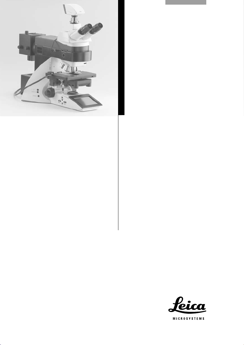
Leica DM5500 B
Leica DM6000 B
Leica DM6000 M
Operating Manual
Bedienungsanleitung
Manuel d’utilisation
1
Page 2

Published September 2007 by:
Herausgegeben September 2007 von:
Publié en septembre 2007 par :
Leica Microsystems CMS GmbH
Ernst-Leitz-Straße
D-35578 Wetzlar (Germany)
Responsible for contents:
Verantwortlich für den Inhalt:
Responsable du contenu :
Dr. Jasna Roeth, Stefan Motyka
(Product manager „Life Science Research“)
(Produktmanager „Life Science Research“)
(Chef de produit „Life Science Research“)
Holger Grasse
(Safety Officer according to MPG §30)
(Sicherheitsbeauftragter nach MPG §30)
(Officier de sécurité selon MPG §30)
In case of questions, please contact the hotline:
Bei Fragen wenden Sie sich bitte an die Hotline:
Pour toute question, contacter l’assistance en ligne: Phone +49(0)64 41-2922 86
Fax +49(0)64 41-2922 55
E-Mail: MQM-Hotline@leica-microsystems.com
2
Page 3
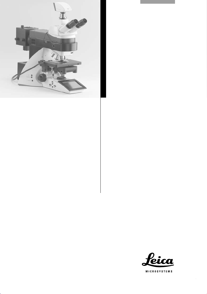
Leica DM5500 B
Leica DM6000 B
Leica DM6000 M
Operating Manual
3
Page 4

Copyrights
Copyrights
All rights to this documentation are held by
Leica Microsystems CMS GmbH. Reproduction
of text or illustrations (in whole or in part) by
print, photocopy, microfilm or other method (including electronic systems) is not allowed without express written permission from Leica
Microsystems CMS GmbH.
The term "Windows" can be used in the following text without further identification. It is a registered trademark of the Microsoft Corporation.
Otherwise, no inference with regard to the free
usability of product names may be drawn from
the use of those names.
The instructions contained in the following
documentation reflect state-of-the-art technology and knowledge standards. We have compiled the texts and illustrations as accurately as
possible. Nevertheless, no liability of any kind
may be assumed for the accuracy of this manual’s contents. Still, we are always grateful for
comments and suggestions regarding potential
mistakes within this documentation.
The information in this manual is subject to modification at any time and without notification.
4
Page 5

Contents
Contents
1. Important Notes about this Manual ...... 7
2. Intended Purpose of Microscopes ........ 8
3. Safety Notes ............................................... 9
3.1 General Safety Notes ............................... 9
3.2 Electrical Safety ........................................ 10
3.3 Disposal ....................................................... 11
4. Overview of the Instrument .................... 12
5. Unpacking the Microscope .................... 18
6. Assembling the Microscope .................. 20
6.1 Stage ............................................................ 21
6.2 Condenser ................................................... 22
6.3 Tube and Eyepieces .................................. 23
6.4 Objectives ................................................... 24
6.5 Light Sources for the
Transmitted Light Axis.............................. 24
6.6 Light Sources for the
Incident Light Axis..................................... 26
6.6.1 106 z lamp housing ......................... 26
6.6.2 External light source EL6000 ........ 31
6.7 Equipping the
Incident Light Turret Disc ........................ 32
6.8 Polarizer and Analyzer ............................. 33
6.9 DIC Prisms .................................................. 34
6.10 Optional Accessories ............................... 35
6.11 Connecting the Leica CTR5500/CTR6000
Electronics Box.......................................... 37
6.12 Connecting the Computer ........................ 38
6.13 Connection to the Power Supply ............ 38
7. Startup ......................................................... 39
7.1 Functional Principle .................................. 39
7.2 Switching on ............................................... 46
7.3 The Leica SmartTouch.............................. 47
7.4 The Function Keys at the stand .............. 48
7.5 The Remote Control Element
SmartMove ................................................. 49
7.6 Köhler Illumination .................................... 49
7.6.1 Transmitted Light ............................ 49
7.6.2 Incident Light................................... 51
7.7 Checking Phase Contrast Rings ............. 52
7.8 Adjusting Motorized Polarizer ................ 54
7.9 Adjusting the Light Sources .................... 54
8. Operation .................................................... 60
8.1 Switching on ............................................... 60
8.2 Stages and Specimen Displacement .... 62
8.2.1 Manual stage (DM5500 B) ............ 62
8.2.2 Motorized stage (DM6000 B/M)... 63
8.3 Focusing ...................................................... 64
8.4 Tubes ........................................................... 65
8.5 Eyepieces .................................................... 67
8.6 Objectives ................................................... 67
8.7 Magnification Changer ............................. 70
8.8 Light Sources ............................................. 70
8.9 Aperture Diaphragm and
Field Diaphragm ......................................... 71
5
Page 6

Contents
9. Contrasting Methods for
Leica DM5500 B and DM6000 B ............. 72
9.1 Transmitted Light....................................... 72
9.1.1 Bright Field....................................... 72
9.1.2 Phase Contrast................................ 73
9.1.3 Dark Field ......................................... 73
9.1.4 Polarization ...................................... 74
9.1.5 Differential Interference Contrast .. 75
9.2 Fluorescence .............................................. 76
9.3 Combi Mode ............................................... 77
10. Contrasting Methods for
Leica DM6000 M ........................................ 78
10.1 Incident Light ............................................. 78
10.1.1Bright Field ....................................... 78
10.1.2Dark Field ......................................... 78
10.1.3Polarization ...................................... 79
10.1.4Interference Contrast .................... 80
10.1.5Fluorescence ................................... 80
10.2 Transmitted Light ....................................... 81
10.2.1Bright Field ....................................... 81
10.2.2Polarization ...................................... 81
11. Trouble Shooting ....................................... 82
12. Care of the Microscope ........................... 85
12.1 Dust Cover .................................................. 85
12.2 Cleaning....................................................... 85
12.3 Handling Acids and Bases ...................... 86
13. Essential Wear and Spare Parts ............ 87
14. Abbreviations and Pictograms .............. 88
15. Index ............................................................ 90
16. EU Declaration of Conformity ................. 91
6
Page 7
1. Important Notes about this Manual
1. Important Notes about this Manual
Caution!
This operating manual is an essential component of the microscope, and must be read
carefully before the microscope is assembled, put into operation or used.
Text symbols, pictograms and their meanings:
(1.2)
→
p.20
!
This operating manual contains important instructions and information for the operational
safety and maintenance of the microscope and
accessories. Therefore, it must be kept and
taken care of.
For the operation of the LeicaScreen and the
Leica Application Suite (LAS), please see
separate operating manual.
Numbers in parentheses, such as "(1.2)", correspond to illustrations (in the example, Figure 1,
Item 2).
Numbers with pointer arrows (for example
→ p.20), point to a certain page of this manual.
Caution!
Special safety instructions within this
manual are indicated with the triangle symbol shown here, and have a gray background.
Caution! The microscope and accessories can
be damaged when operated incorrectly.
Notes on how to dispose of the microscope,
its components and expendables.
Explanatory note.
Item not contained in all configurations
*
(optional).
7
Page 8
2. Intended Purpose of Microscopes
2. Intended Purpose of Microscopes
The Leica DM5500 B and DM6000 B microscopes, to which this user manual belongs, are
designed for biological routine and research
applications. This includes the examination of
samples taken from the human body with a view
to providing information on physiological or
pathological states or congenital abnormalities,
or to determining the safety and compatibility
with potential recipients, or to monitoring therapeutic measures.
The Leica DM6000 M microscope is designed for
examinations in the field of materials research.
All the above-named microscopes comply with
the Council Directive 98/79/EEC concerning in
vitro diagnostics. They also conform to the
Council Directives 73/23/EEC concerning electrical apparatus and 89/336/EEC concerning electromagnetic compatibility for use in an industrial
environment.
The manufacturer assumes no liability for
damage caused by, or any risks arising from
using the microscopes for other purposes
than those for which they are intended or
not using them within the specifications of
Leica Microsystems CMS GmbH.
In such cases the conformity declaration
shall cease to be valid.
These (IVD) devices are not intended for use
in the patient environment defined by DIN
VDE 0100-710. Neither are they intended for
combining with medical devices according
to EN 60601-1. If a microscope is electrically
connected to a medical device according to
EN 60601-1, the requirements defined in
EN 60601-1-1 shall apply.
Caution!
Caution!
8
Page 9
3. Safety Notes
3.1 General Safety Notes
This safety class 1 device is constructed and
tested in accordance with
EN 61010-2-101:2002,
EN 61010-1:2001,
IEC 1010-1:2001,
safety regulations for electrical measuring, control, and laboratory devices.
Caution!
In order to maintain this condition and to ensure safe operation, the user must follow the
instructions and warnings contained in this
operating manual.
3. Safety Notes
Caution!
The devices and accessories described in
this operating manual have been tested for
safety and potential hazards.
The responsible Leica affiliate or the main
plant in Wetzlar must be consulted whenever the device is altered, modified or used
in conjunction with non-Leica components
that are outside of the scope of this manual.
Unauthorized alterations to the device or
noncompliant use shall void all rights to any
warranty claims!
9
Page 10

3. Safety Notes
3.2 Electrical Safety
General specifications
Leica CTR5500 and CTR6000 electronics box
For indoor use only.
Supply voltage:
Frequency:
Power input:
Fuses:
90-250 V~
50-60 Hz
max. 290 VA
T6,3 A
(IEC 60127-2/3)
Ambient temperature:
Relative humidity:
Overvoltage category:
Pollution degree:
15-35°C
max. 80% to 30°C
II
2
Microscope
For indoor use only.
Supply voltage:
Frequency:
Power input:
Fuses:
Ambient temperature:
Relative humidity:
Overvoltage category:
Pollution degree:
90-250 V~
50-60 Hz
See CTR5500/6000
See CTR5500/6000
15-35°C
max. 80% to 30°C
II
2
Supply unit ebq 100*
For indoor use only.
Supply voltage:
Frequency:
Power input:
Fuses:
Ambient temperature:
Relative humidity:
Overvoltage category:
Pollution degree:
90-250 V~
50-60 Hz
max. 155 VA
2xT2A (IEC 127)
10-36°C
max. 80% to 30°C
II
2
(see enclosed manual)
Leica EL6000
For indoor use only.
Supply voltage:
Frequency:
Power consumption:
Fuses:
100-240 V~ (±10%)
50-60 Hz
max. 210 VA
5x20, 2.5 A, slow,
breaking capacity H
→ EL6000 manual
Ambient temperature:
Relative humidity:
0°-40°C
10-90%
non-condensing
Overvoltage category:
Contamination class:
II
2
(see enclosed manual)
Caution!
The power plug may only be plugged into an
outlet equipped with a grounding contact.
Do not interfere with the grounding function
by using an extension cord without a ground
wire. Any interruption of the ground wire inside or outside of the device, or release of
the ground wire connection, can cause the
device to become hazardous. Intentional
ground interruption is not permitted!
10
Page 11
3. Safety Notes
Caution!
Through activating to the grounding connection (earth screw on the back of the Leica
CTR5500 and CTR6000 Electronics Box)
ancillary equipment with its own and/or
extra power supply may be brought to the
same ground wire potential. For connections
without a ground connector, Leica Service
must be consulted.
Caution!
Never use any fuses as replacements other
than those of the types and the current ratings listed here. Using patched fuses or
bridging the fuse holder is not permitted.
Caution!
Caution!
Before exchanging the fuses or lamps, be
absolutely certain to switch-off the main
power switch and remove the power cable.
Caution!
Touch the touchscreen using your finger
only. Never use a pen or other hard, sharp or
pointed objects.
3.3 Disposal
After the end of the product’s life, please
contact Leica Service or Leica Sales on how to
dispose of it.
Please observe the national laws and
ordinances which, for example, implement and
ensure compliance with EU directive WEEE.
The microscope’s electrical accessory components are not protected against water.
Water can cause electric shock.
Caution!
Protect the microscope from excessive temperature fluctuations. Such fluctuations can
lead to the accumulation of condensation,
which can damage the electrical and optical
components.
Ambient temperature: 15-35°C.
n.b.:
Like all electronic instruments, the
microscope, its components and expendables may not be disposed of as general
household waste!
11
Page 12

4. Overview of the Instrument
4. Overview of the Instrument
Specification
Contrasting Method
Transmitted Light Axis
Incident Light Axis
Leica DM5500 B/DM6000 B
• transmitted light:
BF, DF, PH, ICT (DIC), Pol
• incident light: Fluo
• automatic Illumination Manager
(automatic aperture diaphragm and field diaphragm,
automatic intensity control)
• automatic Constant Color Intensity Control (CCIC)
• motorized shutter
• integrated into the stand
• motorized 8x filter turret
( 5x optional)
• with FIM (Fluorescence Intensity Manager) for decreasing light intensity in 5
steps
• mechanical “Booster Lens“
for increasing fluorescence
intensity
• motorized Excitation Manager to control the fluorescence emission when using
double and triple filter cubes
(optional).
• ultra-fast, internal filter
wheel (IFW), motorized
(optional)
• motorized shutter
(speed < 0.1 s)
Leica DM6000 M
• transmitted light: BF, Pol
• incident light:
BF, DF, ICR (DIC), Pol, Fluo
• integrated into the stand
• motorized 4x filter turret
(2 fixed positions, 2 variable
positions)
• automatic Illumination
Manager
• motorized shutter
(speed < 0.1 s)
12
Tube
• motorized or manual
• up to 3 beam splitting positions
• optionally with two camera outputs
(for one digital and e.g. one analog camera)
Page 13

4. Overview of the Instrument
Specification
Magnification Changer
(optional)
Objective Turret
X/Y Stage
Condenser
Leica DM5500 B/DM6000 B
• manual
• absolute coded
• magnification steps:
1x; 1.25x; 1.6x
• DM6000 B: motorized
DM5500 B: manual
• absolute coded
• 7x for objectives with M25
thread
• mot. DIC objective prism turret with 4 positions
(optional)
• DM6000 B/M: motorized, direct stepper motor drive
DM5500 B: manual
• replaceable specimen stage
• zero position defined by end switch
• outer dimensions: 234 mm x 157 mm
• travel range: 76 mm x 50 mm
• smallest increment: 0.3 µm
• motorized condenser head
• automatic change between contrasting methods:
motorized condenser turret for light rings, DF stop,
DIC prisms
• optional polarizer integrated and motorized
• automatic Köhler Illumination
Leica DM6000 M
• manual
• absolute coded
• magnification steps:
1x; 1.5x; 2x
• motorized
• absolute coded
• 6x for objectives with M32
thread
• mot. DIC objective prism
turret with 4 positions
(optional)
Z Drive
• motorized
• dovetail for exchanging stage
• travel range: 25 mm
• smallest increment: 0.015µm
• max. speed: 5 mm/s
• min. speed: 1 mm/s
• max. load: 4 kg
13
Page 14

4. Overview of the Instrument
Specification
Control Panels
Leica CTR5500
Leica CTR6000
Electronics Box
Computer Interface
Software Tools
Leica DM5500 B/DM6000 B Leica DM6000 M
• Function keys at the stand
• additional variable function keys
• focusing knobs
• Leica SmartTouch: touch sensitive LC display
• SmartMove: ergonomic control element
for x,y,z control with additional variable function keys
• Leica STP6000: ergonomic control element for x,y,z
control with 11 additional variable function keys
and touch sensitive LC display
• separate control unit to control
• z-drive
• xy-stage (CTR6000)
• objective turret (CTR6000)
with:
• supply voltage for 100W halogen lamp
• supply voltage for SmartMove
See → p.10 (electrical safety))
• USB 2.0
• Leica Application Suite (LAS)
TM
for Windows
2000, XP, Vista
• for:
• microscope and camera configuration
• microscope and camera control
• image recording and image storing
14
Page 15
4. Overview of the Instrument
2
3
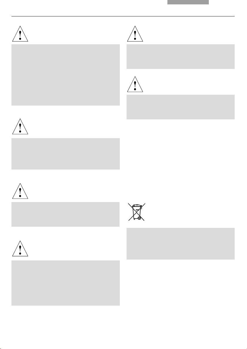
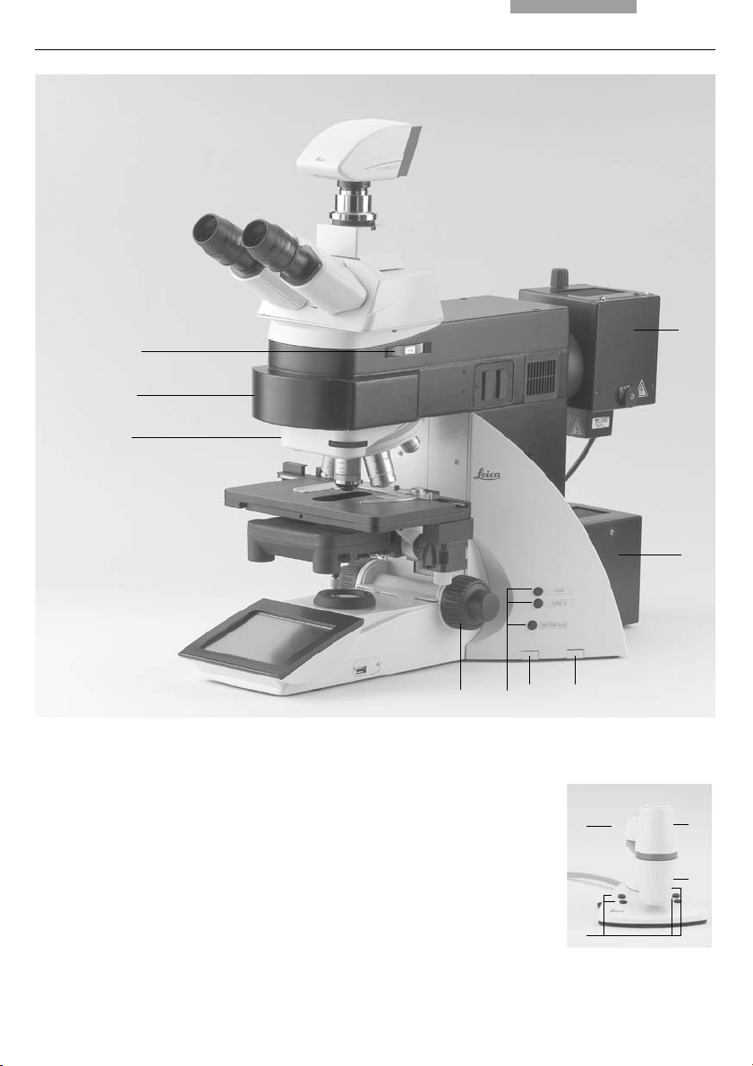
Fig. 1 System overview DM6000 B
4
5
6 7
81
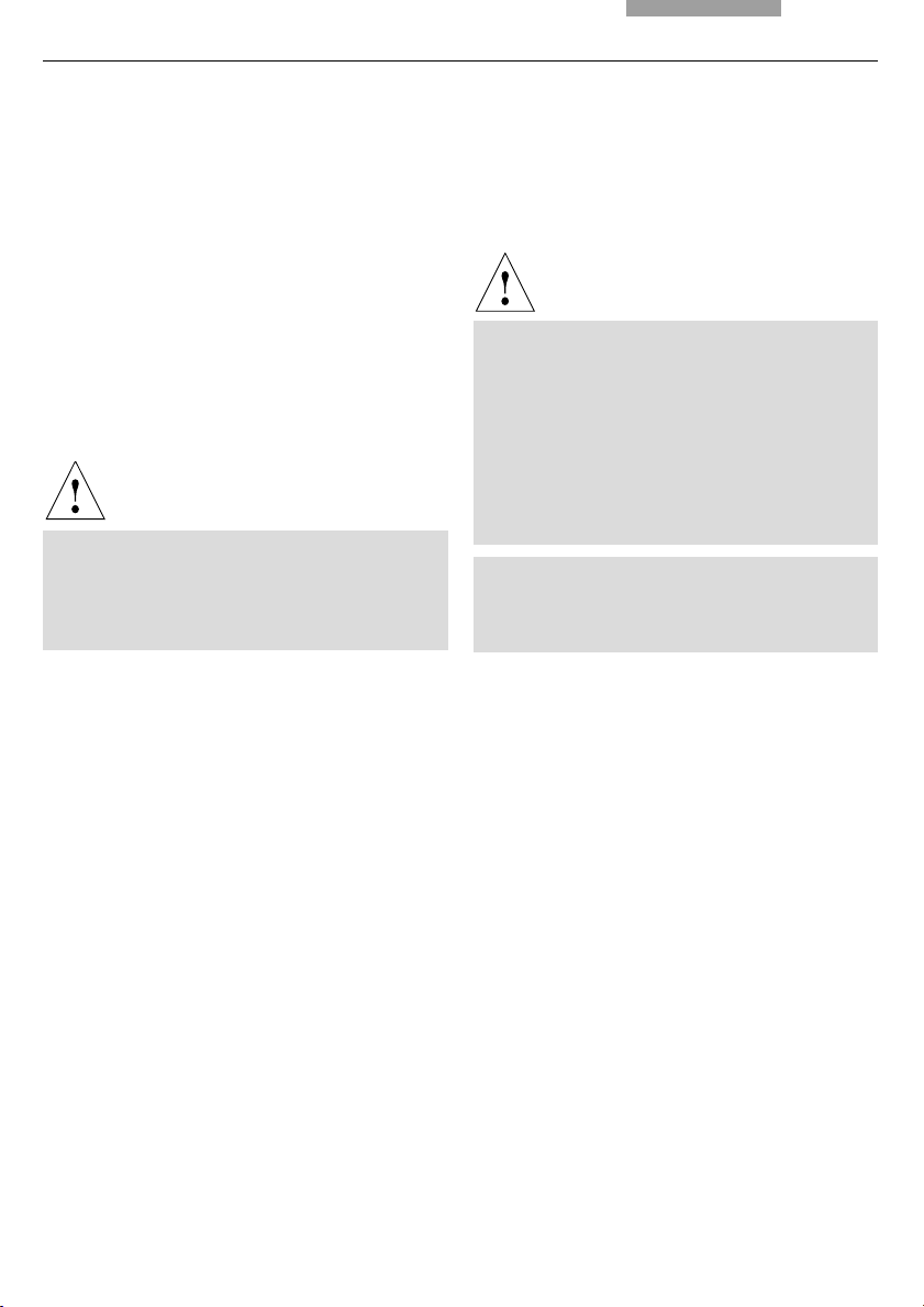
Abb. 1 Control elements of the Leica STP6000
1 Touchscreen
2 Information key
3,4 Variable function keys, user-programmable
5 Fine focus adjustment
6 Coarse focus adjustment
7 Movement in Y direction
8 Movement in X direction
15
Page 16
4. Overview of the Instrument
14
1
2
3
4
5
6
7
13
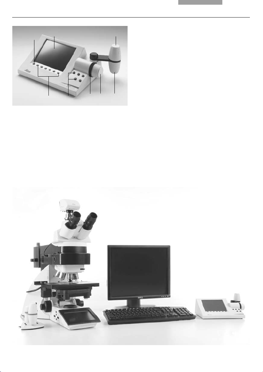
Fig. 2 Left side of the stand Leica DM6000 B
1 Eyepiece
2 Eyepiece tube
3 Motorized tube MBDT
4 Motorized objective nosepiece with objectives
5 Motorized specimen stage with specimen holder
6 Condenser
7 Leica SmartTouch
9101112
8 Function keys field diaphragm
9 Transmitted light/incident light switch
10 Function keys aperture diaphragm
11 Function keys light intensity
12 Focus wheel
13 Variable function keys (factory pre-assigned)
14 Lamp adjustment window
n.b.: Illustrations for Leica DM5500 B similar, but with manual objective nosepiece and manual
specimen stage
16
Page 17
21
4. Overview of the Instrument
15
23
22
16
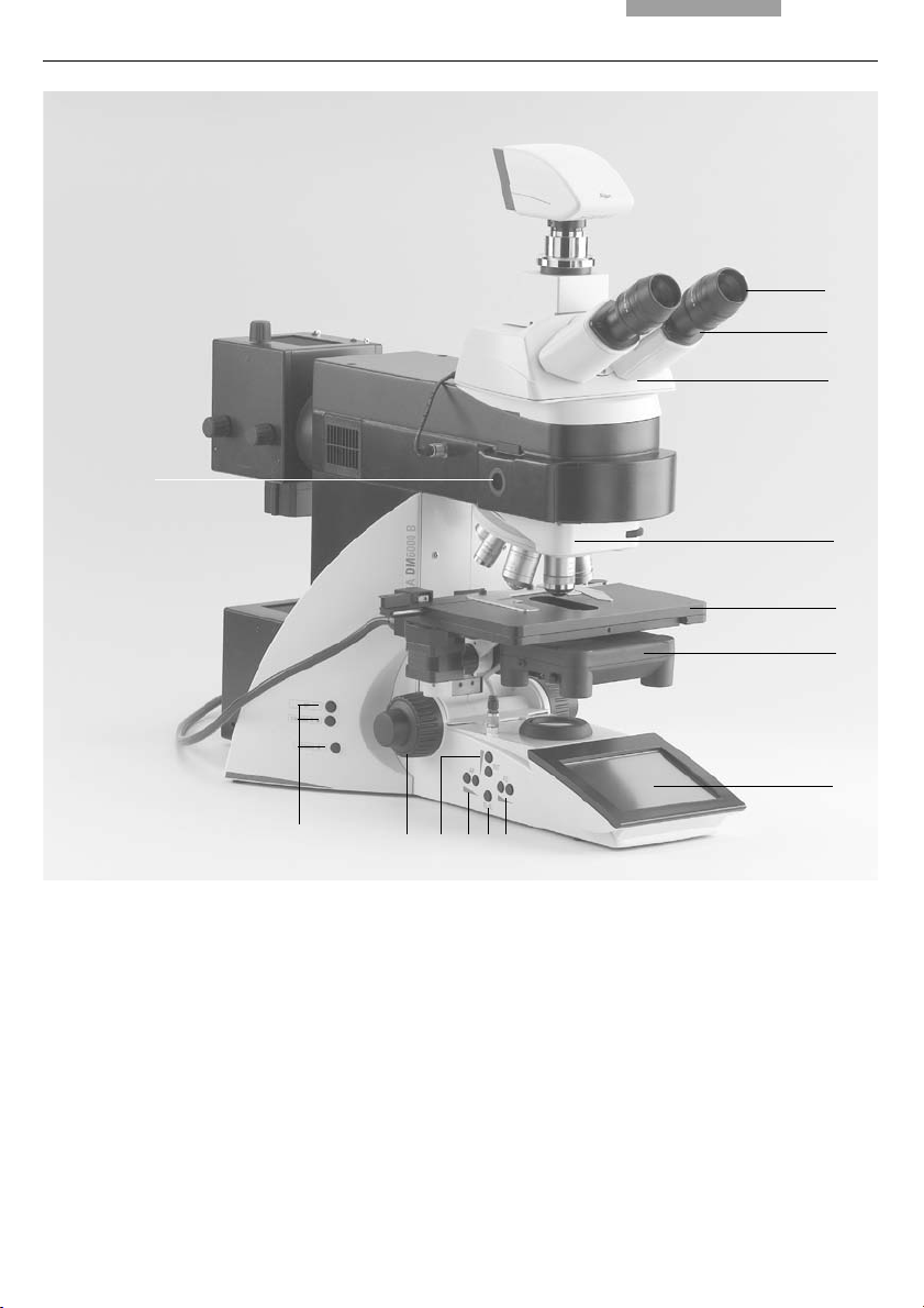
Fig. 3 Right side of the stand Leica DM6000 B
15 Lamp housing for incident light
16 Lamp housing for transmitted light
17 Transmitted light filter, optional
18 Transmitted light filter, optional
19 Variable function keys (factory pre-assigned)
20 Focus wheel
21 DIC turret
22 Motorized filter turret
23 Magnification changer
19
18 17
3
20
Fig. 4 Remote control element SmartMove
1 Movement (x-direction)
2 Movement (y-direction)
3 Focus adjustment
4 Variable function keys
(factory pre-assigned)
4
1
2
17
Page 18
5. Unpacking the Microscope
5. Unpacking the Microscope
The device is delivered in several boxes.
The stand box contains the following compo-
nents:
• Stand with integrated incident light axis and
objective nosepiece
• Specimen stage with stage bracket
• Power cable and PC connecting cable
• CD with software package Leica Application
Suite (LAS)
• Instructions and list of microscope default
settings („Identification Sheet“)
The system box contains the microscope acces-
sories:
• Tube
• Eyepieces
The Leica CTR5500 or CTR6000 Electronics Box,
the remote control element SmartMove, the
external ebq 100 supply unit* and the external
EL6000 compact light source* are delivered in
separate packaging.
First, carefully remove all components from the
transportation and packaging materials.
Note:
If at all possible, avoid touching the lens surfaces of the objectives. If fingerprints do appear
on the glass surfaces, remove them with a soft
leather or linen cloth. Even small traces of finger
perspiration can damage the surfaces in a short
time. See the chapter, "Care of the Microscope"
p. 85, for additional instructions.
→
Caution!
• Objectives
• Condenser
• Lamp housings with accessories
• Fitting tool
• Depending on configuration, additional microscope accessories such as filter cubes, etc.
18
Do not yet connect the microscope and peripherals to the power supply at this point!
Page 19

5. Unpacking the Microscope
Installation location
Work with the microscope should be performed
in a dust-free room, which is free of oil vapors
and other chemical vapors, as well as extreme
humidity. At the workplace, large temperature
fluctuations, direct sunlight and vibrations
should be avoided. These conditions can distort
measurements and micrographic images.
Allowable ambient conditions
Temperature 15-35°C
Relative humidity maximum 80% up to 30°C
Microscopes in warm and warm-damp climatic
zones require special care in order to prevent
the build up of fungus.
See the chapter, "Care of the Microscope" →
for additional instructions.
Caution!
Electrical components must be placed at least
10 cm from the wall and away from flammable substances.
p. 85,
Transport
For shipping or transporting the microscope
and its accessory components, the original
packaging should be used.
As a precaution to prevent damage from vibrations, the following components should be disassembled and packaged separately:
• Unscrew the objectives.
• Remove the condenser.
• Remove the stage.
• Remove the lamp housings.
• Disassemble the burner of 106 z lamp housing.
• Remove all moving or loose parts.
19
Page 20

6. Assembly
6. Assembling the Microscope
The microscope components are logically assembled in this order:
• Stage
• Condenser
• Tube
• Eyepieces
• Objectives
• Light sources
• Filter cubes/reflectors*
Only a few commonly used screwdrivers and
keys are necessary for assembly, which are included in the delivery package.
When using intermediate systems and optical
accessories, the sequence may vary.
In this case, read Chapter
"6.10 Optional accessories" → p. 35.
20
Page 21
6.1 Stage
Caution:
!
Before assembling the stage, make sure no objectives are installed!
6. Assembly
Note:
For thicker specimens (Leica DM6000 M) the
stage can be set to a correspondingly lower
level.
• Place the specimen holder on the stage and
fasten it with the two screws (5.1).
• Using the condenser height adjuster (5.2), turn
the condenser holder completely upwards, i.e.
as close to the stage as possible.
• Loosen the stage clamp (5.3) slightly.
• From above, set the stage clamp onto the
dovetail guide (6.2) and push the stage downwards until the upper end of the dovetail guide
is tightly fastened to the upper end of the
stage clamp.
• Firmly tighten the stage clamp (6.1).
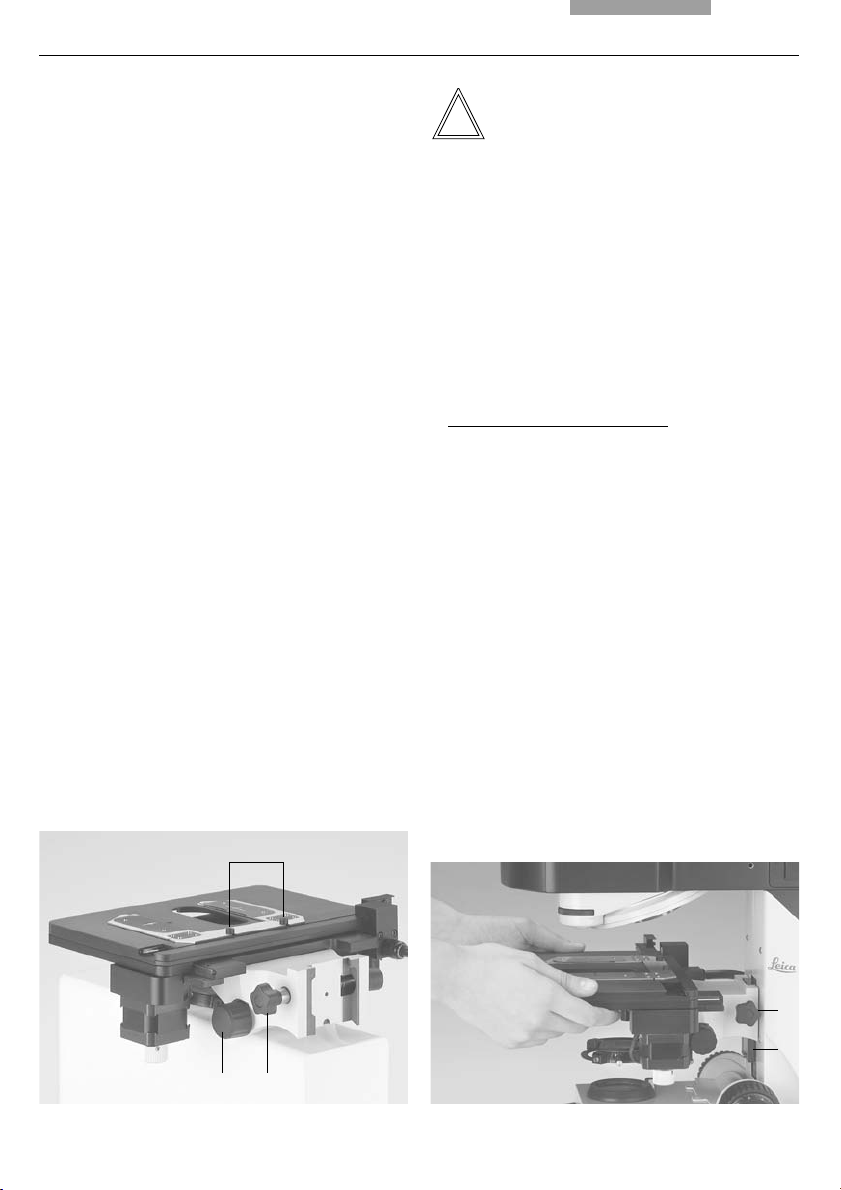
Fig. 5 Object stage (motorized)
1 Locking screws for specimen holder
2 Condenser height adjuster
3 Stage clamp
1
Caution:
!
This changes the pre-set focus position and the
lower threshold. Both positions have to be set
again. See 8.3. Focusing, → p. 64.
For the motorized stage only:
•
Connect the stage cable to the electronics
box Leica CTR6000.
See chapter 6.11 → p. 37.
Fig. 6 Assembling the stage
1 Stage clamp
2 Dovetail guide
23
1
2
21
Page 22
6. Assembly
6.2 Condenser
• Screw the condenser head into the condenser.
• Using the condenser height adjuster (7.4), turn
the condenser holder (7.1) completely downwards.
• Unscrew the clamping screw for the condenser (7.3) far enough so that the condenser
can be inserted from the front.
• From the front, insert the condenser into the
condenser holder as far as it will go. On the
underside of the condenser, there is an orientation pin (8.1), which must be located in the
guiding notch (9.1).
• Pull the condenser’s clamping screw (7.3) so
that the condenser is locked in place.
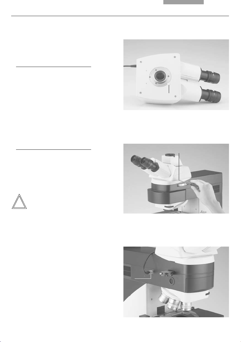
• Connect the condenser by connecting the
condenser cable (10.1) with the stand. The
black index point on the stand points to the
groove of the plug.
Note:
The condenser must be centered before using
the microscope.
Köhler illumination p. 49.
→
Fig. 8
Underside of condenser
1 Orientation pin
Fig. 9 Condenser holder
1 Guiding notch
1
1
Fig. 7 Condenser holder
1 Condenser holder
2 Condenser centering
3 Clamping screw for condenser
4 Condenser height adjuster
1
2
3
22
Fig. 10 Condenser connector
1 Condenser cable socket
1
4
Page 23
6. Assembly
6.3 Tube and Eyepieces
The tube is mounted to the stand either directly or
with the use of intermediate modules. It is fastened
in place with the side clamping screw (12.1).
Only for the motorized tube MBDT:
•
Remove the transportation lock (11.1) from the
bottom side of the tube.
• Loosen the clamping screw (12.1). on the
stand.
• Insert the tube in the circular receptacle
(dovetail ring).
• Retighten the clamping screw (12.1).
Only for the motorized tube MBDT:
•
Connect the tube to the stand with the connector socket (13.1).
• The eyepieces are inserted into the eyepiece
tubes on the tube.
Fig. 11 Bottom side of the tube
1 Transportation lock
1
Fig. 12 Fastening the tube
1 Clamping screw
1
Note:
For eyepieces that are not included in shipment,
we recommend to learn them in with the
Software Leica Application Suite (LAS), module:
Set-Up. This ensures that the information about
total magnification on the LeicaScreen is
correct.
Fig. 13 Motorized tube connection
1 Connector socket
1
23
Page 24
6. Assembly
6.4 Objectives
The receptacles on the objective turrets are
numbered (Fig. 14). The individual objectives
have already pre-assigned positions at the factory according to their configuration.
A list of the exact objective positions is provided
in shipment (“Identification Sheet”).
Caution:
!
Cover unoccupied threads on the turret with
dust protector caps!
Note:
We recommend to perform a parfocality adjustment with the Software Leica Application Suite
(LAS), module: Fine Tuning.
6.5 Light Sources for the Transmitted Light Axis
Caution!
Be sure that the lamp housing is disconnected from the power supply. Unplug the
power plug and the power supply during assembly.
Caution!
Light sources pose a potential irradiation
risk (glare, UV-radiation, IR-radiation).
Therefore, lamps have to be operated in
closed housings.
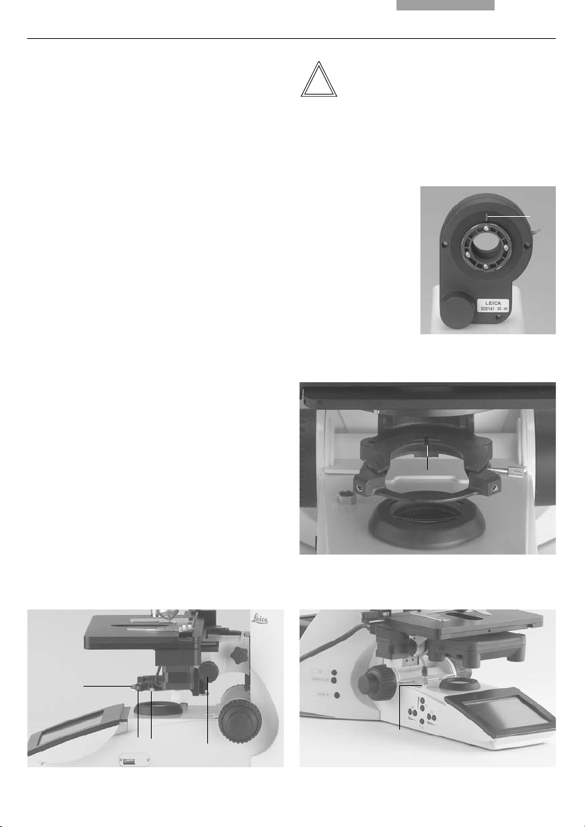
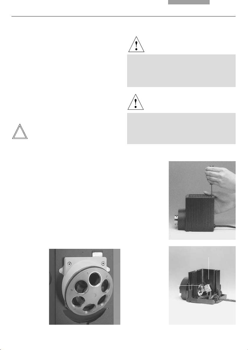
Fig. 15
Releasing the
fastening screw
at lamp housing 107/2
Fig. 14
Objective turret
with labeled
objective
receptacles
24
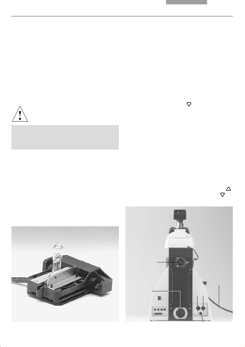
Fig. 16
Lamp housing 107/2,
opened
1 Mount with
halogen lamp
2 Collector
1
2
Page 25
6. Assembly
107/2 Lamp Housing
This lamp housing is used with a 12V 100W halogen lamp, which is already mounted.
In case the lamp has to be removed:
• Remove the fastener screw on the housing
(Fig. 15).
• Remove the housing by pulling it upwards.
• Remove the lamp.
• Insert the new 12V 100W lamp (16.1) with the
dust cover straight into the socket until it
stops. Be sure that the lamp is inserted
straight.
• Remove the lamp’s dust cover.
Caution!
Do not remove the lamp’s dust cover until
you have installed the lamp. Avoid fingerprints on the lamp.
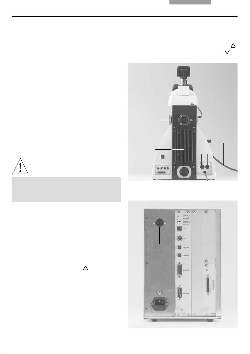
Fig. 17 Rear side of stand
1 Incident light lamp housing receptacle
2 Transmitted light lamp housing receptacle
3 12 V 100 W connection for transmitted light (symbol: )
4 12 V 100 W connection for incident light (symbol: )
5 Lamp power cable
1
5
2
Fig. 18 Rear side of Leica CTR6000
1 Connection for lamp power cable from the stand
34
• Replace the housing and fasten it in place using the fastening screw.
• Place the lamp housing in the transmitted light
lamp housing receptacle (17.2) and fasten it
with the clamping screw on the side.
• Connect the lamp housing to the power supply
for transmitted light (symbol:
) (17.3).
• Now connect the lamp power cable of the microscope (17.5) to the Leica CTR5500 or
CTR6000 Electronics Box (18.1).
1
25
Page 26
6. Assembly
6.6 Light Sources for the Incident Light Axis
Caution!
Light sources pose a potential irradiation
risk (glare, UV-radiation, IR-radiation).
Therefore, lamps have to be operated in
closed housings.
During assembly, always unplug the power
supply unit of the 106 z lamp housing from its
socket.
During assembly work on xenon burners, always wear the supplied protective gloves
and face protection (Fig. 19) (risk of explosion).
Never touch the glass parts of the burner
with bare hands.
Never look directly into the beam path
(blinding hazard).
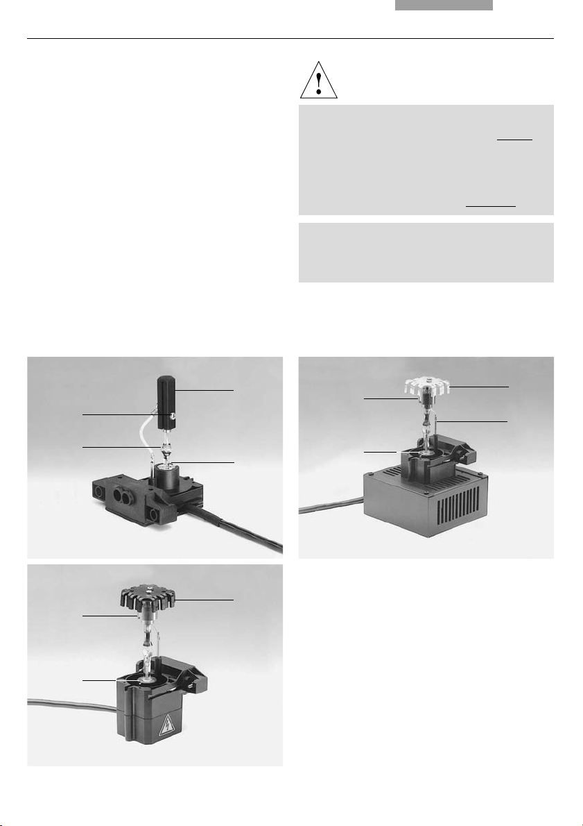
6.6.1 106 z lamp housing
This lamp housing is used with a 12V 100W halogen lamp or various gas discharge lamps.
Caution!
Make sure to follow the instructions and
safety notes of the lamp supplier.
Before changing lamps allow at least 30 mins
for cooling down!
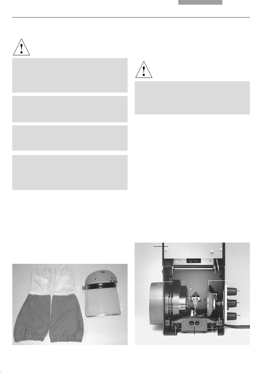
Fig. 20 106 z lamp housing (on the side, open)
1 Cover raised
2 Collector
3 12 V 100 W lamp or
gas discharge lamp in mount
4 Reflector (mirror)
5, 6, 7 Adjusting screw for x-y reflector
8 Fastening screw for lamp mount
9 Socket for contact plug
Fig. 19
Protective gloves and mask
26
1
2
4
5
3
6
7
898
Page 27
6. Assembly
Inserting the 12V 100W halogen lamp into the
106 z lamp housing
• Unscrew the fastening screws of the cover
and lift up the cover (20.1).
• Unscrew the fastening screws of the lamp
mount (20.8) and pull out the mount (Fig. 21).
• Insert the lamp with the dust cover straight
into the socket until it stops.
Caution!
Do not remove the lamp’s dust cover until
you have installed the lamp. Avoid fingerprints on the lamp.
• Remove the dust cover.
• Reinsert the lamp mount and retighten the
fastening screw (20.8).
• Close the lamp housing and retighten the fastening screws.
• Place the lamp housing in the incident light
lamp housing receptacle (22.1) and fasten it
with the clamping screw on the side.
• Connect the lamp housing to the power supply
for incident light (symbol
) (22.4).
• Now connect the lamp power cable of the microscope (22.5) to the Leica CTR5500 or
CTR6000 electronics box (18.1, p. 25)
Fig. 22 Rear side of stand
1 Incident light lamp housing receptacle
2 Transmitted light lamp housing receptacle
3 12 V 100 W connection for transmitted light (symbol: )
4 12 V 100 W connection for incident light (symbol: )
5 Lamp power cable
Fig. 21 Lamp mount with 12 V 100 W halogen lamp
1
5
2
34
27
Page 28

6. Assembly
Inserting the gas discharge lamps (Hg and Xe)
into the 106z lamp housing
Hg and Xe lamps are powered by separate supply units.
Read the separate instruction manual provided
with these supply units.
The following gas discharge lamps may be used
and require different supply units and lamp
mounts (Fig. 23):
Type Typical bulb life*
50 W high-pressure mercury burner (alternating current) 100 hrs.
100 W high-pressure mercury burner (direct current) 200 hrs.
100 W high-pressure mercury burner (direct current, type 103 W/2) 300 hrs.
75 W High-pressure xenon burner (direct current) 400 hrs.
* Please regard the data sheets of the burners.
28
Page 29
• To open the 106 z lamp housing, unscrew the
fastening screws on the cover.
6. Assembly
Caution!
• Remove the transport anchorage (red plastic
rod in place of the burner) in the lamp mount.
To do so, remove the lower clamp (23.1). Pull
up the cooling element (23.3) and turn it to the
side. Detach the lower clamp system (23.2)
and remove the transport anchorage.
• Install the burner in reverse order.
Fig. 23 a-c Lamp mounts for gas discharge lamps
1 Upper clamping system, 2 Lower clamping system, 3 Cooling element
4 Nipple of the mercury 50 burner, 5 Dust cover of the mercury 75 burner
Hg 50
1
4
a
3
2
Hg 50 burner:
After installation, the labeling must be upright.
If a glass melt nipple is present (23a.4), position it by turning the burner so that the nipple
does not come in the way of the beam path
later, but instead is positioned
Xe 75 burner:
Remove the burner’s dust cover (23b.5) after
you have installed the burner.
Xe 75
sideways.
b
3
1
5
2
Hg 100
1
2
c
3
29
Page 30
6. Assembly
• Insert the lamp mount, with the burner installed, into the lamp housing and tighten it
with the screws (24.8).
• Put the lid down again. Plug in the contact
plug as far as it goes and retighten the
screws.
• Place the lamp housing in the incident light
lamp housing receptacle (25.1) and fasten it
with the clamping screw on the side.
• Connect the lamp housing to the power supply
(26.1).
Fig. 25 Rear side of stand
1 Incident light lamp housing receptacle
2 Transmitted light lamp housing receptacle
3 12 V 100 W connection for transmitted light (symbol: )
4 12 V 100 W connection for incident light (symbol: )
5 Lamp power cable
Fig. 24 106 z lamp housing (on the side, open)
1 Cover raised
2 Collector
3 12 V 100 W lamp or
gas discharge lamp in mount
4 Reflector (mirror)
5, 6, 7 Adjusting screw for x-y reflector
8 Fastening screw for lamp mount
9 Socket for contact plug
1
2
3
898
4
5
6
7
30
Fig. 26 Rear side of the ebq 100 supply unit
1 Lamp connection
1
1
5
2
34
Page 31

6.6.2 Leica EL6000 compact light source
• Instructions on inserting the lamp are given in
the Leica EL6000 compact light source
manual.
• The microscope adapter for connecting the
light guide is attached to the back of the stand
(22.1).
Caution!
Connect the light guide to the microscope
first to prevent exposing the user to the
high-energy light output of the Leica EL6000
compact light source.
6. Assembly
Caution!
Connect the light guide at both ends (light
source/adapter) before opening the shutter
or attenuator.
The emitted light may result in eye or skin
injuries or damage to materials.
Never look directly into the light emitted by
the light guide.
Further information →
Fig. 27 Light guide with adapter
1 Light guide
2 Adapter for Leica microscopes
Leica EL6000 manual.
• Insert the light guide (27.1) into the
microscope adapter (27.2) and secure it with
the clamping screw. Insert the opposite input
of the light guide into the port (28.1) on the
rear panel of the compact light source. The
light guide must click into place.
!
Caution!
Take care not to kink or otherwise damage the
light guide when connecting it to the light
source or microscope adapter. Do not
overtighten the clamping screw.
Use only light guides with Storz long connectors
to prevent damage to the unit and danger to the
user (blinding hazard).
12
Fig. 28 Rear panel with connectors
1 Light port
2 Remote control port
3 AC input
2
1
3
31
Page 32

6. Assembly
6.7 Equipping the Incident Light Turret Disc
The receptacles on the turret are numbered. According to your equipment, the individual filter
and/or reflector cubes have already pre-assigned positions. A list is provided along with
your shipment (“identification sheet“).
Insert the filter and reflector cubes in the following manner:
• Equip the incident light turret only when the
microscope is switched off.
• Remove the front cover from the upper part of
the microscope (Fig. 30a). Push the retention
pin (30a.2 or 30b.2) to move the turret.
Releasing the retention pin locks the turret.
• Insert the filter or reflector cube into the
mounting in front of you according to the identification sheet provided.
To do so, place the filter or reflector cube on
the right side and press it to the left into the
mounting (Fig. 31).
Fig. 30a Removing the front cover
(4-fold filter turret)
1 Filter receptacle
2 Retention pin
3 Front cover
1
2
3
Fig. 30b 8-fold filter turret
(front cover removed)
1 Filter receptacle
2 Retention pin
1
2
Fig. 29a Filter cube
front side
32
Fig. 31 Inserting the filter or reflector cubes
1 Mounting
Fig. 29b Filter cube
back side
1
Page 33

6.8 Polarizer and Analyzer
6. Assembly
Note:
At the 4-fold and 5-fold filter turrets, the numbers are right below the mounting. At the 8-fold
turret, the numbers are on the bottom of the
disc.
• Push the retention pin (30a.2 or 30b.2) and
continue to turn the filter turret until you
reach the next locking position.
• Again make sure that the turret engages (retention pin unlocks) and insert the next filter
and/or reflector cube as described above.
• When all filters and reflector cubes have been
inserted, close the front cover plate again.
Note:
At the Leica DM6000 M, 2 positions for bright
field and dark field reflector cubes may be set
(depending on configuration).
ICT/P transmitted light polarizer
• Using the left clamping screw, fasten the ICT/P
transmitted light polarizer to the underside of
the condenser holder (Fig. 32).
• Make sure that the red index point on the front
of the polarizer is aligned with 0.
• If necessary, insert the compensators (λ- and
λ/4 plates) into the polarizer’s receptacle
(Fig. 33).
Incident light polarizers:
R/P polarizer, rotating polarizer
L/ICR, R/ICR polarizer
• Remove the plug cap on the right side of the
incident light axis (Fig. 34).
• Insert the polarizer into the receptacle until it
latches in place.
Attention:
!
Note:
Filter cubes that are not included in shipment
have to be learned in with the Software Leica
Application Suite (LAS), module: Set-up.
Insert the polarizer only in the front receptacle!
Fig. 32 Assembly of the ICT/P transmitted light polarizer
1 Clamping screw
1
33
Page 34

6. Assembly
Motorized polarizer
• A motorized polarizer is already installed and
ready for operation in the DIC condenser.
Transmitted light and incident light analyzer
• Remove the plug cap on the left side of the
stand.
• Insert the analyzer into the receptacle until it
latches in place (Fig. 35).
Motorized analyzer
• Insert the analyzer cube as described in section 6.7 "Equipping the Incident Light Turret
Disc" → p. 32, in the corresponding position on
the filter turret. See the list provided (“Identification Sheet”) for the correct position.
6.9 DIC Prisms
With the microscopes Leica DM5500 B and
DM6000 B the DIC objective prisms are already
mounted in the DIC turret above the objective
revolving nosepiece (Fig. 34.2).
Fig. 33 Inserting the compensators
Fig. 34 Inserting the polarizer
1 The plug cap is replaced with the polarizer.
2 Knurled wheel for fine adjusting the DIC prisms
1
2
34
Fig. 35 Inserting the analyzer
1 The plug cap is replaced with the analyzer.
1
Page 35

6.10 Optional Accessories
6. Assembly
Camera
Connecting a camera
A camera can be connected via c-Mount or
Vario-Mounts.
• Attach the c-Mount or the Vario-Mount to the
top port of the tube and fasten it tightly with
the side clamping screw.
• Screw on the camera.
Note:
The use of a c-Mount or a Vario-Mount should
be learned in with the Software Leica
Application Suite (LAS), module: Set-up.
Connecting two cameras
The dual port enables you to connect two cameras (one digital and e.g. one analog) to the microscope.
• When using a DC-type digital camera, the
camera is connected to the PCI-card of the
PC.
Note:
Please see the separate operating manual of the
digital camera.
Note:
When retrofitting the tube with a dual port, both
ports should be centered by the technical service.
• When using a DFC-type digital camera, the
camera is connected to the Fire Wire card of
the PC.
35
Page 36

6. Assembly
Ergomodule
For raising the eye level of the tube opening, the
ergomodule may be used.
It is fastened in place with the side clamping
screw.
Mirror Housing
• Place the mirror housing directly onto the
lamp housing receptacle on the back of the
stand and attach it using the side clamping
screw.
• Place the lamp housing onto the mirror housing and fasten it using the corresponding
clamping screw on the side.
Manual Booster Lens
Manual Excitation Manager
• Insert the filter slide into the front receptacle
on the right side of the stand (36.1, 37.1).
• Booster Lens and manual Excitation Manager
can not be used simultaneously.
n.b.:
The motorized Excitation Manager is already
built in at the factory.
Fig. 36
1 Insert of Booster Lens
36
Fig. 37
1 Insert of Excitation Manager
1
1
Page 37

6. Assembly
6.11 Connecting the Leica CTR5500 or CTR6000
Electronics Box
Note:
We generally advise you not to use the Leica
CTR5500 or CTR6000 box with other microscopes. The serial no. of the matching stand
can be found on the rear side of the electronics
box.
• Plug one connector of the 25-pin cable into
the socket on the back of the microscope
(38b.2) and the other into the Microscope port
(38a.6).
Fig. 38a Rear side of Leica CTR6000
1 AC power socket
2 XY Stage socket for motorized stage
3 XYZ Control for SmartMove
4 Trigger
5 Ext socket
6 USB-interface
7 12V, max 100W for lamp power cable of the stand
8 DL: reset button
9 Microscope socket for microscope
• Connect the remote control element SmartMove to the socket XYZ-Control (38a.5).
For CTR6000 only:
• Connect the motorized stage to the socket XY-
Stage (38a.2).
• If the lamp power cable of the microscope
(38b.3) has not been connected during assembly, connect it now to the socket 12V, max
100W (38a.7).
Caution!
To avoid overheating of the ports, make sure
the plugs are connected properly and
screwed on tightly.
Fig. 38b Rear side of stand
1 USB-interface
2 Connection to the Leica CTR5500 or CTR6000
electronics box
3 Lamp power cable of the microscope
4 Ext1/Ext2 sockets
7
8
6
5
4
3
2
1
9
1
4
2
3
37
Page 38

6. Assembly
6.12 Connecting the Computer
• Connect the USB serial interface of the computer to the USB (38b.1) port on the back of
the stand. Use the USB cable sup-plied.
6.13 Connection to the Power Supply
• After completing the assembly work, connect
the Leica CTR5500 or CTR6000 electronics box
to the power supply using the power cable
supplied (port 38a.1).
• When using the ebq 100 supply unit, this
also has to be connected to the power supply
(port 39a.1).
• If using the compact light source Leica
EL6000, connect it to the power supply as well
(port 39b.1).
Fig. 39a Rear side of the ebq 100 supply unit
1 Port for power supply cable
1
38
Fig. 39b Rear panel of the EL6000 compact light source
1 Port for power supply cable
1
Page 39

7. Startup
7. Startup
7.1 Functional Principle
Based on an intelligent automation concept, the Leica DM5500 B or DM6000 B/M can be operated
via several control elements.
1. Intelligent automation
• Switch between different contrasting methods by pressing just one button. Light rings,
DIC-prisms, etc. are inserted into the beam path automatically.
• The microscope recognizes the objective in use and the corresponding contrasting
method. Therefore, the values for intensity (INT), aperture diaphragms (AP) and field diaphragms (FD) are always set appropriately.
• The information about INT, AP and FD is always given with regard to the currently activated
light axis (transmitted light or incident light).
• The values for INT, AP and FD can be changed individually. This overwrites the previous
settings. Actual settings are stored automatically and can be recalled when switching on
the microscope again.
2. Control elements
• Leica SmartTouch: Controls the microscope’s functions via touch screen.
• SmartMove: For stage and focus control
• Leica STP6000: For stage and focus control and the microscope's functions via touch screen
• Fixed function keys at the stand
For INT, AP, FD and to switch between transmitted light and incident light.
• Variable function keys at the stand, at the SmartMove, Leica STP6000
The function keys are assigned logical functions before delivery, corresponding to the configuration of your microscope. These functions can be re-programmed according to your
individual requirements.
• Entire control of microscope and camera via software
(Leica Application Suite, Leica application software)
39
Page 40

7. Startup
Note: (Reset-Function)
The microscope can be reset to the default
settings:
• When the microscope is switched off,
press all 3 variable function keys (40.1) on
the left stand section.
• Switch on the stand.
• Hold the keys pressed down until initialization is completed.
• The standard information is shown in the
LeicaScreen.
• Switch off the instrument and switch it on
again. The settings are stored now.
The table on the opposite page shows which microscope components can be operated with
which control elements.
Fig. 40 Left side of the microscope
1 Variable function keys
1
40
Page 41

7. Startup
Function LeicaScreen Fixed Variable Turning Knobs Software
Function Function SmartMove LAS
Keys at Keys at the STP6000
the Stand Stand, at the
SmartMove,
STP6000
Change contrasting methods + - (+) - +
Toggle between TL and IL + +--+
Select objectives (DM6000 only) + - (+) - +
learn in parfocality - ---+
change operating mode + ---+
(Dry/Imm)
Illumination manager - + (+) - +
Magnification changer* manual operation only
Focusing ---+1)+
set thresholds + ---+
go to thresholds + - (+) - +
change step size + ---+
(Coarse/Fine)
XY-stage positioning ---++
(motorized stage only)
change speed + ---+
go to/set stage positions - ---+
Motorized tube* + - (+) - +
(change beam splitting)
Select filter/reflector cube + + (+) - +
+ always possible
(+) optional
- not possible
1)
Focusing also possible via manual focus knobs
41
Page 42

7. Startup
Possible assignments for the variable Function Keys at the stand and at the SmartMove
For Leica DM5500 B and DM6000 B:
Function key Meaning
BF Bright field (transmitted light)
PH Phase contrast (transmitted light)
ICT Interference contrast (transmitted light)
DF Dark field (transmitted light)
POL Polarization (transmitted light)
CHANGE_TL
INT_TL_UP Increase brightness (transmitted light)
INT_TL_DOWN Reduce brightness (transmitted light)
FD_TL_UP Open field diaphragm (transmitted light)
FD_TL_DOWN Close field diaphragm (transmitted light)
AP_UP Open aperture diaphragm (transmitted light)
AP_DOWN Close aperture diaphragm (transmitted light)
SHUTTER_TL Open/close transmitted light shutter
FLUO Fluorescence (last filter cube)
CUBE_n Select fluorescence cube at position n
CUBE_CW Switch through fluorescence cubes in clockwise fashion
CUBE_CCW Switch through fluorescence cubes in counterclockwise fashion
CHANG_FLUO Switch through all fluorescence cubes
SHUTTER_FL Open/close fluorescence shutter
Switch through all transmitted light processes
FD_FL_UP Open field diaphragm (fluorescence)
FD_FL_DOWN Open field diaphragm (fluorescence)
CHG_FW Switch through all filter wheel functions
IFW Activate internal filter wheel
EXMAN Activate Excitation Manager
FIM Activate Fluorescence Intensity Manager
COMBI_CONT
CHG_COMBI
CHG_TUBE Toggle between different beam splitting modes
100%_VIS 100% Documentation port
50:50 50% Documentation port/50% Camera
100%_CAM 100% Camera
42
Combination mode (PH/fluorescence or ICT/fluorescence)
Switch through all combination modes
Page 43

Function key Meaning
OBJ_n Select objective at position n (DM6000 B only)
OBJ _1-7 Switch through objectives 1 to 7 (DM6000 B only)
OBJ_7-1 Switch through objectives 7 to1 (DM6000 B only)
DRY/IMM Switch between DRY / IMM objectives
TOP_IN/OUT Swing condenser top in/out
SHEARING+ Change objective prisms for DIC
Z_FINE Activate fine focus
Z_COARSE Activate coarse focus
Z_FINE/CO Switch between fine and coarse focus
FOCUS_POS Move to focus position
LOWER_Z_PO Move to lower focus threshold
XY_PRECISE Activate stage step size "precise" (DM6000 B only)
XY_FAST Activate stage step size "fast" (DM6000 B only)
MEMn Move to memory position n (DM6000 B only)
XYZ_MODE Switch between stage step size "precise" /fine focus and
stage step size "fast" /coarse focus
7. Startup
CHGMHPATH Switch through all possible mirror house positions
- Function key not assigned
43
Page 44

7. Startup
For Leica DM6000 M:
Function key Meaning
BF_RL Bright field (incident light)
ICR Interference contrast (incident light)
DF_RL Dark field (incident light)
POL_RL Polarization (incident light)
CHANGE_RL
INT_RL_UP Increase brightness (incident light)
INT_RL_Down Reduce brightness (incident light)
FD_RL_UP Open field diaphragm (incident light)
FD_RL_Down Close field diaphragm (incident light)
AP_RL_UP Open aperture diaphragm (incident light)
AP_RL_Down Close aperture diaphragm (incident light)
SHUTTER_RL Open/close incident light shutter
BF Bright field (transmitted light)
PH Phase contrast (transmitted light)
ICT Interference contrast (transmitted light)
DF Dark field (transmitted light)
POL Polarization (transmitted light)
TL_IMC IMC contrast (transmitted light)
CHANGE_TL
INT_TL_UP Increase brightness (transmitted light)
INT_TL_DOWN Reduce brightness (transmitted light)
FD_TL_UP Open field diaphragm (transmitted light)
FD_TL_DOWN Close field diaphragm (transmitted light)
AP_UP Open aperture diaphragm (transmitted light)
AP_DOWN Close aperture diaphragm (transmitted light)
SHUTTER_TL Open/close transmitted light shutter
TL_FLT_1 Select transmitted light filter 1
TL_FLT_2 Select transmitted light filter 2
Switch through all incident light processes
Switch through all transmitted light processes
FLUO Fluorescence (last filter cube)
CUBE_n Select fluorescence cube at position n
(for incident light CUBE_2 corresponds to position 4)
CUBE_CW Switch through fluorescence cubes in clockwise fashion
CUBE_CCW Switch through fluorescence cubes in counterclockwise fashion
CHANG_FLUO Switch through all fluorescence cubes
SHUTTER_FL Open/close fluorescence shutter
FD_FL_UP Open field diaphragm (fluorescence)
FD_FL_DOWN Open field diaphragm (fluorescence)
FOCUS_FIND Select smallest field diaphragm
and switch back to original field diaphragm by pressing the key again
44
Page 45

Function key Meaning
CHG_FW Switch through all filter wheel functions
IFW Activate internal filter wheel
EXMAN Activate Excitation Manager
FIM Activate Fluorescence Intensity Manager
7. Startup
COMBI_CONT
CHG_COMBI
CHG_TUBE Toggle between different beam splitting modes
100%_VIS 100% Documentation port
50:50 50% Documentation port/50% Camera
100%_CAM 100% Camera
OBJ_n Select objective at position n
OBJ+ Go to next higher objective
OBJ- Go to next lower objective
OBJ _1-7 Switch through objectives 1 to 7
OBJ_7-1 Switch through objectives 7 to1
DRY/IMM Switch between DRY / IMM objectives
TOP_IN/OUT Swing condenser top in/out
SHEARING+ Change objective prisms for DIC
Z_FINE Activate fine focus
Z_COARSE Activate coarse focus
Z_FINE/CO Switch between fine and coarse focus
FOCUS_POS Move to focus position
LOWER_Z_PO Move to lower focus threshold
XY_PRECISE Activate stage step size "precise"
XY_FAST Activate stage step size "fast"
MEMn Move to memory position n
Combination mode (PH/fluorescence or ICT/fluorescence)
Switch through all combination modes
XYZ_MODE Switch between stage step size "precise" /fine focus and
stage step size "fast" /coarse focus
CHGMHPATH Switch through all possible mirror house positions
- Function key not assigned
45
Page 46

7. Startup
7.2 Switching on
• Start with the objective with the lowest magnification.
• Switch on the Leica CTR5500 or CTR6000
Electronics Box at the on/off switch (41.1).
When in operation, the pilot lamp will light up
green (41.2). All motorized microscope
components first undergo an initialization
phase.
Note:
If you have connected a PC, please switch on
the electronics box first and the computer afterwards.
After initialization is completed, the Leica
SmartTouch shows the current microscope setting (Fig. 42).
If one of the components is not mounted properly, e.g. the cover of the filter turret is not
locked in place, an error will show up on the
Leica SmartTouch.
See chapter ‘Trouble Shooting’, → p. 84.
The microscopic components such as diaphragms, condenser, light and phase rings are
already pre-centered in the factory. However,
re-centering may be necessary due to transportation and assembly.
Before proceeding with the necessary steps,
first familiarize yourself with the Leica
SmartTouch and control panel.
Caution!
After turning on the gas discharge lamp, the
burner must be immediately adjusted. Therefore, do not turn on the power supply unit
yet. First, work in transmitted light in order to
familiarize yourself with the microscope’s
controls.
Fig. 41
Front view of the
Leica CTR6000 box
1 On/off switch
2 Pilot lamp
46
Fig. 42 LeicaScreen after initialization
2
1
Page 47

7. Startup
7.3 The Leica SmartTouch
On the status page, the Leica SmartTouch
shows the current microscope settings. The display depends on the microscope’s configuration.
Apart from this, the microscope can be operated
via several menu levels on the LeicaScreen.
Please see the abbreviation index for a list of
abbreviations used →
p. 88.
Read the separate instruction manual of the
Leica SmartTouch.
The display represents different levels of operation:
Level 1: Navigation panel
Level 2: Menu bar
Level 3: Information and control panel
After selecting a pictogram on the navigation
panel (left column on the display), the corresponding menu bar opens in the upper row of
the display. The items on the control panel
change accordingly. The currently active functions are highlighted in black..
Navigation panel
The navigation panel allows for quickly selecting the navigation items:
Basic microscope settings
Contrast methods
Magnification
Stage and focus controls
Microscope configuration
SmartTouch-configuration
Menu Bar
Menu bar
Navigation panel Information and control panel
Each navigation item contains several menus
that can be selected via the menu bar. The currently activated menu is highlighted in black.
Information and control panel
This area shows the current settings and functions that can be operated from this menu.
Items that are compatible with the current settings are marked with a black triangle.
47
Page 48

7. Startup
7.4 The Function Keys at the stand
There is a row of function keys both on the right
and left side of the stand. Some of these keys
are defined, and some of them are variable. The
variable function keys have various meanings
depending on the microscope configuration.
Defined Function Keys on the left side of the
stand
The TL/IL key (43.1) switches between incident
light and transmitted light. The last contrast
method used is restored.
The INT (43.3) keys adjust the light intensity individually. Settings can be made either in large or
small increments. Pushing both INT buttons at
the same time switches between coarse and
fine setting. If the fine setting has been selected,
the display indicates „Intensity fine“.
The AP (43.2) keys for the aperture diaphragm
and FD (43.4) for the field diaphragm are used
to open/close each diaphragm.
Variable Function Keys at the stand
A factory preset is performed which fits your
microscope configuration. The function keys are
labeled accordingly, and a separate description
of the key occupation accompanies the microscope (“Identification Sheet“).
Abbreviations are listed on p. 42f.
Note:
The setting of the variable function keys can
only be altered via the Software Leica
Application Suite, module: Set-up.
Note:
Changes in light intensity and settings of aperture and field diaphragms are stored for the current objective and contrasting method.
48
Fig. 43 Defined Function Keys
1 Transmitted light/incident light
2 Aperture diaphragm
3 Light Intensity
4 Field diaphragm
2
3
4
1
Page 49

7. Startup
7.5 The Remote Control Element SmartMove
Turning knobs at the SmartMove
The specimen stage of the DM6000 B and M can
be moved in x/y direction with the turning knobs
(44.1, 44.2). The image can be focused with the
turning knob (44.3).
The height of the turning knobs can be adjusted
to your individual needs with the screw (44.4).
Variable function keys at the SmartMove
The function keys are assigned logical functions
before delivery, corresponding to the configuration of your microscope. The keys are labeled
accordingly. For the setting of the keys, see
‘Identification Sheet’.
For the list of abbreviations see page → 42f.
Note:
The setting of the variable function keys can
only be altered via the Software Leica
Application Suite (LAS), module: Set-up.
Fig. 44 Remote Control Module SmartMove
1 Move in x-direction
2 Move in y-direction
3 Focus
4 Height adjustment
5 Variable function keys (factory pre-set)
1
3
4
2
5
7.6 Köhler Illumination
7.6.1 Transmitted Light
For each objective, reasonable values for the
aperture diaphragm and the field diaphragm are
already set. The condenser is also pre-adjusted
in the factory.
However, it may be necessary to re-adjust the
condenser in some cases. Therefore, check the
condenser centering.
The following procedure is provided for the
transmitted light-bright field illumination.
Fig. 45 Stage with specimen holder
1 Specimen holder
2 Condenser height adjuster
1
2
49
Page 50

7. Startup
• Select an objective with moderate magnifica-
tion (10x-20x).
• If necessary, activate the transmitted light
axis by pushing the TL/IL button (43.1).
• Choose "bright field" as the contrast method
by pressing the BF key (one of the variable
function keys at the stand, STP6000 or at the
Leica SmartTouch).
• Insert the specimen in the stage’s specimen
holder (45.1).
• Focus on the specimen with the SmartMove,
STP6000 or focus wheel.
• Set the light intensity using the INT keys
(43.3).
• Close the field diaphragm with the FD function
key (43.4) until the edge of the diaphragm appears in the specimen plane.
• Using the condenser height adjuster (45.2),
adjust the condenser until the edge of the
field diaphragm appears in sharp relief.
• If the image does not appear in the middle of
the field of view (47c), the condenser must be
moved into the middle of the field of view with
the help of the two centering bolts (46.1).
• Open the field diaphragm just enough for it to
disappear from the field of view (47d).
Caution:
The light of the condenser depends on the thickness of the specimen. It has to be adjusted for
each specimen.
Fig. 46 Condenser centering
1 Centering bolts
11
50
Fig. 47 Köhler Illumination
a Field diaphragm not focused, not centered
b Field diaphragm focused, but not centered
c Field diaphragm
Diameter is too small, however
d Field diameter (light) = Field diameter (view)
(Köhler Illumination)
a
cd
b
Page 51

7. Startup
7.6.2 Incident Light
For each objective there are reasonable values
assigned to aperture and field diaphragm. The
incident light module is also pre-centered at the
factory.
Due to transportation and setup of the stand,
however, you might have to re-center the incident light module. Please check the aperture
and field diaphragm centering.
The following procedure refers to the incident
light bright field illumination.
• Select an objective with moderate magnification (10x-20x)
• If necessary, activate the incident light axis by
pressing the TL/IL key (43.1).
• Activate the bright field contrasting method by
pressing IL-BF/Fluo (one of the variable function keys at the stand, STP6000 or at the Leica
SmartTouch).
• Insert the specimen in the stage’s specimen
holder (45.1).
• Focus on the specimen with the SmartMove,
STP6000 or focus wheel.
• Adjust the light intensity with the INT keys
(43.3).
Adjusting the field diaphragm
• Close the field diaphragm with the FD keys
(43.4) until the edge of the diaphragm (round
or rectangular) appears on the specimen
plane.
• If the boundaries of the field diaphragm are
not in the center of the field of view, the diaphragm has to be moved with the two
centering bolts (48a.1) on the right side of the
stand.
• With the function keys FD (43.4) on the left
side of the stand, open the field diaphragm until it just disappears from the field of view.
• When using a digital camera, rectangular field
diaphragms are recommended. Adjust the
size of the diaphragm to the chip size of your
camera.
Fig. 48a Adjusting the field diaphragm in the incident light
axis
1 Centering bolts for moving the field diaphragm
1
Fig. 48b Adjusting the aperture diaphragm in the incident
light axis
1 Centering bolts for moving the aperture diaphragm
1
51
Page 52

7. Startup
Adjusting the aperture diaphragm
(DM6000 M only)
• Remove one eyepiece.
• Close the aperture diaphragm with the AP
keys (43.2) until the edge of the diaphragm appears on the exit pupille of the objective (aperture field plane).
• If the image does not appear in the center of
the field of view, the aperture diaphragm has
to be moved with the two centering bolts
(48b.1) on the upper left side of the stand.
• Open the aperture diaphragm so it covers
approx. 2/3 of the field of view.
7.7 Checking Phase Contrast Rings
If your microscope is equipped for the use of
phase contrast, the light rings that fit the objectives are built into the condenser.
The light rings are already centered in the factory. However, the centering should be
rechecked.
Note:
Every objective is assigned its own light ring in
the condenser disc. Therefore, a check must be
performed for each objective. When swiveling in
a suitable objective for phase contrast, the corresponding light ring is set automatically.
• Press the BF (Bright Field) button (one of the
variable function keys at the stand, STP6000
or at the Leica SmartTouch).
• In the place of an eyepiece, insert the focusing telescope (Fig. 49) into the observation
tube.
Fig. 49 Focusing telescope
1 Adjustable eyelens
2 Clamping ring for fixing the focus position
1
2
52
• Select the phase contrast objective with the
lowest magnification (one of the variable
function keys at the stand or at the
SmartMove).
• Focus on the specimen with the SmartMove,
STP6000 or focus wheel.
Page 53

7. Startup
• Focus the ring structure (50a) by slightly loosening the clamping ring (49.2) and moving the
eyelens (49.1).
• Retighten the clamping ring.
• Press the PH (Phase Contrast) button (one of
the variable function keys at the stand or at
the LeicaScreen). The ring diaphragm in the
condenser is pivoted in.
• If the light ring and the phase ring are not
shown as arranged in Fig. 50c, the light ring
must be centered.
• Insert the centering key through the corresponding openings (51.1) in the condenser
holder.
• Turn the centering screws until the dark ring
(phase ring in the objective) is congruent with
the slightly narrower bright ring (light ring in
condenser) (50 c).
Caution!
During change of objectives the centering
keys must not remain in the openings of the
condenser. They can block the condenser.
• Repeat the process for all other phase contrast objectives.
• Remove the centering keys after the centering
procedure.
Fig. 50 Phase contrast centering procedure
PH=phase contrast ring, LR=light ring
a Condenser in bright field (BF) position
b Condenser in phase contrast (PH) position
Light ring (LR) not centered
c Light ring and phase ring centered
ab c
Fig. 51 Light ring centering
1 Centering key
2 Opening for centering of motorized polarizer
1
2
53
Page 54

7. Startup
7.8 Adjusting Motorized Polarizer
• Select POL contrast method (one of the variable function keys at the stand, STP6000 or at
the Leica SmartTouch).
• Inserting centering key through the corresponding opening (51.2).
• Turn it until maximum darkness is reached.
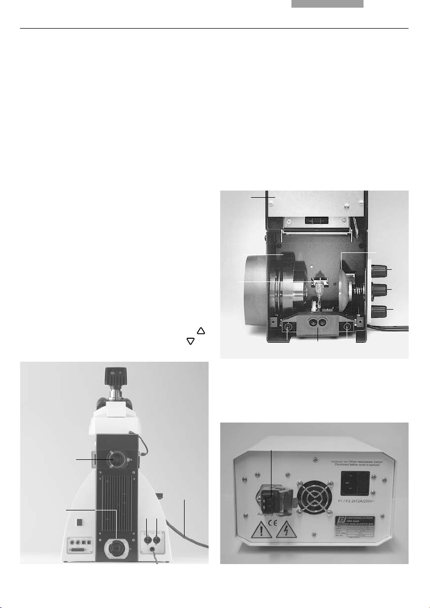
7.9 Adjusting the Light Sources
Transmitted Light Axis (TL) with 107/2 Lamp
housing
The 107/2 lamp housing with 12 V 100 W halogen
lamp has a defined presetting. The lamp need
not to be centered.
Incident light axis (IL) with external light
source Leica EL6000
This lamp does not need centering.
Incident light axis (IL) with 106 z lamp housing
• When a supply unit is used, it is turned on
first.
• Activate the incident light axis using the TL/IL
function key. FLUO (Leica DM5500 B/DM6000 B)
or IL (Leica DM6000 M) appears in the Leica
SmartTouch.
• Insert the reflector cube for lamp adjustment
(Fig. 52) into the filter turret in place of a filter
cube. (See →
p. 32).
Note the name of the exchanged filter cube.
Fig. 52 Reflector cube for lamp adjustment
54
Note:
To avoid incorrect adjustment, we recommend
to remove the filter cube on the left side of the
reflector cube.
• Turn the reflector into the beam path.
The reflector has reached the correct position
when the name of the exchanged filter cube is
shown in the upper right of the LeicaScreen.
Page 55

Caution!
Never look directly into the beam path!
When switching to the BF or Smith reflectors,
there is a danger of being glared!
Caution!
Light sources pose a potential irradiation
risk (glare, UV-radiation, IR-radiation).
For the 106 z lamp housing, the direct filament image (for halogen lamps) or direct arc image (for
gas discharge lamps), and its mirror image are focused separately and adjusted to each other.
On the left side of the microscope, there is an
adjustment window (1.14, p. 16) for mapping the
light source.
While observing the light source in the adjustment window, the lamp is adjusted as follows:
7. Startup
Fig. 53 106 z lamp housing
1 Lamp height adjustment
2,4 Mirror image height and side adjustment
3 Focusing the reflector
5 Lamp side adjustment
6 Collector (focusing of the lamp image)
516
2
3
4
55
Page 56

7. Startup
Centering the 12 V 100 W Halogen Lamp
• In the adjustment window, you see the direct
filament image and the mirror image, which in
most cases are not aligned.
• Focus the direct filament image with the collector (53.6).
• Use the adjusting buttons on the rear side of
the lamp housing (53.2, 53.4) to pivot the lamp
filament’s mirror image to the side or completely out of the beam path. The lamp filament’s focused image remains visible (Fig. 54).
• Adjust the direct filament image using the adjusting knobs (53.1) and (46.5) so that the
centering surface is halfway covered (Fig. 55).
• Then pivot the lamp filament’s mirror image
with the adjusting knobs (53.2 and 4), and focus it using the reflector (53.3).
• Align the mirror image symmetrically to the filament image (Fig. 56). To do so, use the adjusting knobs (53.2) and (53.4) again.
Fig. 54 Direct lamp filament image focused,
but not centered
(in reality, the image is less focused)
Fig. 55 Direct lamp filament image in target position
(in reality, the image is less focused)
• Defocus the image with the collector head
(53.6) until the filament image and mirror image are no longer recognizable and the image
is homogeneously illuminated.
• Exchange the reflector cube for lamp adjustment for the original filter cube.
Note:
Turn off the microscope before exchanging
the reflector cube.
56
Fig. 56 Direct lamp filament image and mirror image in
target position
(in reality, the image is less focused)
Page 57

7. Startup
Centering the Hg 50 W mercury lamp
• In the adjustment window, you see the direct
arc image and the mirror image, which in most
cases are not aligned.
• Focus the direct image with the collector
(53.6).
• Use the adjusting buttons on the rear side of
the lamp housing (53.2,53.4) to pivot the arc’s
mirror image to the side or completely out of
the beam path. The lamp filament’s focused
image remains visible (Fig. 57).
• Use the adjusting buttons (53.1) and (53.5) to
place the direct arc image right or left on an
imaginary center line of the centering plane
(Fig. 58).
• Then pivot the arc’s mirror image with the adjusting knobs (53.2 and 4) and focus it using
the reflector (53.3).
• Use the adjusting knobs (53.2 and 4) to orient
the mirror image symmetrically to the direct
image (Fig. 59).
Fig. 57 Direct arc image focused but decentered
(in reality, the image is less focused)
Fig. 58 Direct arc image in target position
(in reality, the image is less focused)
• Defocus the image with the collector knob
(53.6) until the arc image and mirror image are
no longer recognizable and the image is homogeneously illuminated.
• Exchange the reflector cube for lamp adjustment for the original filter cube.
Fig. 59 Direct arc image and mirror image in target
position (in reality, the image is less focused)
57
Page 58

7. Startup
Centering the Hg 100 W and Xe 75 W
mercury lamps
• In the adjustment window, you see the direct
arc image and the mirror image, which in most
cases are not aligned.
• Focus the direct image with the collector
(53.6).
• Use the adjusting buttons to pivot the arc’s
mirror image on the rear side of the lamp
housing (53.2,53.4) to the side or completely
out of the beam path. The arc’s focused image remains visible (Fig. 60).
• Use the adjusting buttons (53.1 and 5) to place
the direct arc image in the middle of the
centering plane, whereby the bright tip of the
arc, the focal spot, should lie slightly outside
the center (Fig. 61).
• Then pivot the arc’s mirror image with the adjusting knobs (53.2) and (53.4) and focus it using the reflector (53.3).
Fig. 60 Direct arc image focused but not centered
(in reality, the image is less focused)
Fig. 61 Direct arc image in target position
(in reality, the image is less focused)
• Use the adjusting knobs (53.2 and 4) to orient
the mirror image symmetrically to the direct
image (Fig. 62).
The V-shaped irradiation of the direct image
and mirror image arcs can be superimposed.
Caution!
The bright tips of the arcs, the focal spots, must
never be projected onto each other, as this results in a danger of explosion by overheating.
58
Fig. 62 Direct arc image and mirror image in target
position (in reality, the image is less focused)
Page 59

Caution:
In older lamps, the structure of the arc is no
longer clearly recognizable. The image is
then more like that of a HG 50 lamp. The image and mirror image can no longer be superimposed exactly. In this case, align both
images.
• Using the collector, defocus the image with
the knob (53.6) until the arc image and mirror
image are no longer recognizable and the image is homogeneously illuminated.
• Exchange the reflector cube for lamp adjustment for the original filter cube.
Note:
Turn off the microscope before exchanging
the reflector cube.
7. Startup
59
Page 60

8. Operation
8. Operation
8.1 Switching on
When using a gas discharge lamp, the ebq 100
external supply unit must be turned on separately (63b.1).
The external light source Leica EL6000 (if used)
also has to be switched on at the power switch
(63c.1).
Switch on the Leica CTR5500 or CTR6000
Electronics Box at the on/off switch (63a.1).
When in operation, the pilot lamp will light up
green (63a.2).
Note:
If you have connected a PC, please switch on
the electronics box first and the computer afterwards.
Fig. 63b Front view of the ebq 100 supply unit
1 Power switch
2 Lamp status
All motorized components will run through an
initializing phase.
Fig. 63a
Front view of the
Leica CTR6000 box
1 On/off switch
2 Pilot lamp
2
1
Fig. 63c Front side of Leica EL6000 compact light source
1 Power switch
2 Intensity control
60
1 2
2
1
Page 61

Note:
If initializing failed (“InitError” on the Leica
SmartTouch), please see chapter “Trouble
Shooting”, → p. 84.
During initialization, the stage will move to a
pre-set position. The stage is lowered. The motorized tube will be set to the 100% VIS position.
All most recently used settings will be recalled.
!
Caution:
The focus position (DM5500 B and DM6000 B
only) and the lower threshold will also be
stored when switching off the microscope.
8. Operation
After the initialization is completed, the status
menu of the Leica SmartTouch (Fig. 64) shows
the current microscope setting.
Note: (Reset-Function)
The microscope can be reset to the default settings:
• When the microscope is switched off,
press all 3 variable function keys (65.1) on
the left stand section.
• Switch on the stand.
• Hold the keys pressed down until initialization is completed.
• The standard information is shown in the
Leica SmartTouch.
Fig. 64 LeicaScreen, menu page ‘Status’
• Switch off the instrument and switch it on
again. The settings are stored now.
Fig. 65 Left side of microscope
1 Variable function keys
1
61
Page 62

8. Operation
8.2 Stages and Specimen Displacement
8.2.1 Manual stage (DM5500 B)
The stage can be moved with the coaxial pinion
(fig. 66a.1, 66a.2).
Lengthening the coaxial pinion
• For lengthening, pull the lower grip (66a.2)
downwards. Repeat with the upper grip
(66a.1).
Torque adjustment
The torque can be individually adjusted using
two knurled rings (66a.3, 66a.4).
Rotating the stage
The swiveling range of the rotating stages is
0°- 110°.
• In order to revolve the stage, loosen the fastening screw (66a.1).
• Bring the table into the desired position.
• Retighten the fastening screw.
62
Fig. 66a Revolving object stage
1 Object motion (Y direction)
2 Object motion (X direction)
3 Torque adjustment (Y direction)
4 Torque adjustment (X direction)
3
1
2
4
Page 63

8. Operation
8.2.2 Motorized stage (DM6000 B/M)
Specimen Displacement with SmartMove
The motorized stage can be moved with the
turning knobs (66b.1, 66b.2) at the remote control
element SmartMove or STP6000 (66c.7, 66c.8).
Setting the step sizes
There are two velocities for stage movement:
Fast and Precise. In the Fast mode, the velocity
is the same for
all objectives.
In the Precise mode, the velocity is adjusted to
objective in use.
the
Switch between Fast and Precise via
Leica SmartTouch, navigation item
Variable function keys at the stand and at
the SmartMove
STP6000
Software Leica Application Suite, module:
Acquire
Fig. 66b Remote Control Module SmartMove
1 Move in x-direction
2 Move in y-direction
3 Focus
4 Height adjustment
5 Variable function keys (factory pre-set)
Store and recall stage positions
With the Software Leica Application Suite, module: Acquire, different stage positions can be
temporarily stored. Only the XY position is
stored, not the current Z-position.
Apart from the loading position (Load), up to 5
additional stage positions can be temporarily
stored. The current position is displayed on the
XYZ menu of the LeicaScreen. When switching
on the microscope, the stage will move to a
defined starting position after initialization.
Store temporarily /recall stage positions via
Software Leica Application Suite, module:
Acquire
Abb. 1 Control elements of the Leica STP6000
1 Touchscreen
2 Information key
3,4 Variable function keys, user-programmable
5 Fine focus adjustment
6 Coarse focus adjustment
7 Movement in Y direction
8 Movement in X direction
1
2
81
3
4
2
5
3
4
5
6 7
63
Page 64
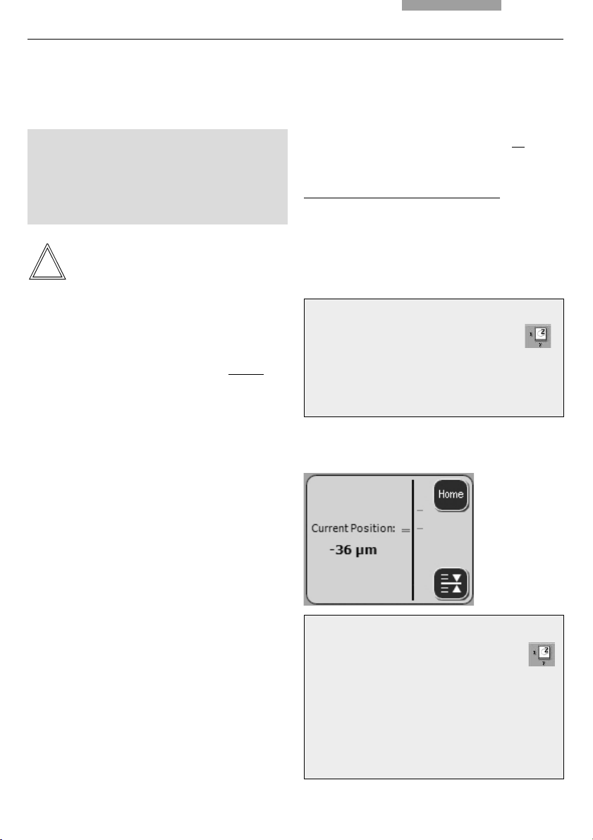
8. Operation
8.3 Focusing
!
Caution:
Make sure that the transmitted light
polarizer* is in the light path when the stage
is lowered to the bottom position. If it is
turned out of the light path, it may damage
the condenser plug.
Note:
Parfocality has been learned in at the factory.
Mounting the objectives, however, can change
the values so that parfocality has to be learned
in again.
We recommend to check parfocality
ting the thresholds. If necessary, it can be
learned in with the Software Leica Application
Suite, module: Fine Tuning.
Image Focus
You can focus by using the turning knob (66b.3)
on the remote control element SmartMove or
Leica STP6000.
before set-
Setting thresholds
The lower threshold can be set with the
LeicaScreen and with the Software Leica
Application Suite.
The lower threshold is the same for
tives and can not be overrode.
Leica DM5500 B and DM6000 B only:
An additional focus position, which can not be
overrode, can be set. This position should be set
for the DRY objective with the highest magnification. For all other objectives it will be set automatically, regarding parfocality and working distance.
all objec-
Setting thresholds via:
LeicaScreen – navigation item
Leica STP6000
Software Leica Application Suite, module:
Fine Tuning
When the thresholds are set, this will be displayed on the Leica SmartTouch:
Alternatively, you can use the focus wheels on
both sides of the stand.
The current Z-position is displayed on the status
page of the Leica SmartTouch. When switching
on the microscope, before initialization the zdrive will automatically go to a position which is
3mm below the most recently used Z-position.
64
Go to thresholds via:
Leica SmartTouch – navigation item
Variable function keys at the stand and at
the SmartMove
Leica STP6000
Software Leica Application Suite, module:
Fine Tuning or Acquire
Page 65

Note:
8. Operation
8.4 Tubes
When using the UPPER Z and LOWER Z keys to
go to a threshold, the keys have to be pressed
until the final position is reached.
There are two step sizes: Fine and Coarse.
In the Fine mode, the value is adjusted to the
objective in use. The values are pre-defined. The
settings can be changed with the Software
Leica Application Suite, module: Fine Tuning.
In the Coarse mode, the value is the same for
all
objectives. Coarse represents the maximum velocity.
Note:
When you assign a certain step size to an objective, this does not only affect the Z-drive but also
the stage-step size that is assigned to this objective when selecting the Precise mode.
Switch between Fine and Coarse via:
Leica SmartTouch – navigation item
Note:
Close any unused tube openings, as otherwise
stray light can interfere with observation.
Note:
Make sure that the connector cable is plugged
in on the MBDT25+ motorized tube (67.1).
Adjusting the Viewing Distance
• Adjust the viewing distance of the eyepieces so that a congruent total image is seen
(Fig. 67).
Adjusting the Viewing Angle
• For the AET22 and EDT22 ergotubes, the viewing angle can be adjusted by tilting the binocular viewer in the range of 5° - 32° (Fig. 68)
Variable function keys at the stand and at
the SmartMove
Leica STP6000
Software Leica Application Suite, module:
Acquire
Fig. 67 Tube setting
↔ Personal eyebase settings
1 Motorized tube connection
1
↔
65
Page 66

8. Operation
Adjusting the Eyepiece Section to the Arm
Length
• On the AET22 tube, the eyepieces can be
extended up to 30 mm (Fig. 68).
Beam Splitting in Photo Tubes
EDT22 tube:
The beam splitting between the observation and
documentation outputs has a definite presetting
(50:50).
BDT25+ tube:
The beam splitting is set manually by pulling out
a control bar.
Control Bar Observation Photo
VIS 100 % 0 %
50/50 150 % 50 %
PHOTO 110 % 100 %
MBDT25+ tube:
This tube is similar to the documentation tube
BDT25+, but it is motorized.
The control positions are displayed on the status
page of the Leica SmartTouch.
After switching on, the position 100%VIS is set
automatically.
Fig. 68 AET22 tube individual adjustments
Key Observation Photo
VIS 100 % 0 %
50/50 50 % 50 %
PHOTO 0 % 100 %
Select beam splitting via:
Leica SmartScree – navigation item
Variable function keys at the stand
Leica STP6000
Software Leica Application Suite, module:
Acquire
HC L 2TU tube:
The beam splitting is set manually by pulling out
a control bar.
Control Bar Observation Photo
VIS 100 % 0 %
PHOTO 110 % 100 %
Note:
Using a duo mount, the beamsplitting between
the two cameras is either fixed at 50:50 or
switchable (100% to the camera at the top or
100% to the camera at the back), depending on
the mount.
Fig. 69 BDT25+ tube with digital camera
1 Control bar
66
1
Page 67

8.5 Eyepieces
Note:
The eyepiece’s aperture protector must be removed or at least folded back, during
microscopy while wearing eyeglasses.
We recommend to take off glasses with bifocal
or progressive-addition lenses when working
with the microscope.
• For the adjustable tubes with documentation
output, choose the 100% VIS position.
Eyepieces with Inlaid Reticle
• Focus the reticle by adjusting the eyelens.
• Focus on the object through this eyepiece.
• Then, close that eye and focus on the specimen by adjusting only the second ocular.
Correction for Vision Problems
8. Operation
Note:
For eyepieces that are not included in delivery,
we recommend to learn them in with the Software Leica Application Suite, module: Set-up.
This ensures that the information about total
magnification on the Leica SmartTouch is correct.
8.6 Objectives
Selecting objectives
Objectives are changed manually on the
DM5500 B. On the DM6000 B/M, the objectives
can be selected and rotated into the beam path
via motorized functions, by pressing the variable
function keys at the stand or at the SmartMove.
They can also be selected manually. In this case
be sure that the nosepiece turret locks into
place.
The objective’s position in the turret is factoryset and must be adhered to while screwing in
the objectives (see Objective Assembly → p. 24)
• With your right eye, look through the right
eyepiece and bring the specimen into sharp
focus.
• Then, with your left eye, view the same specimen and rotate the left eyepiece tube until the
object is brought into sharp focus. This does
not affect the Z-position.
When you rotate the objective into position, the
microscope
• the optimal setting for the field diaphragm
• the optimal setting for the aperture diaphragm
• the settings for light intensity for the chosen
contrast methode.
The objective magnification and the total magnification appear in the Leica SmartTouch → p. 61.
automatically recalls:
67
Page 68

8. Operation
• Start with a small level of magnification. Then
switch to the next higher objective.
• For immersion objectives use the appropriate
immersion medium.
OIL: only use optical immersion oil
according to DIN/ISO standards.
Cleaning → p. 85
W: Water immersion.
IMM: Universal objective for water, glycerol,
oil immersion.
Caution!
Follow safety data sheet for immersion oil!
Selecting objectives (DM6000 B/M) via:
Leica SmartTouch – navigation item
Variable function keys at the stand and at
the SmartMove
Leica STP6000
Software Leica Application Suite, module:
Acquire
Manual operation is possible
Changing the operation mode DRY or IMM (Immersion)
Each objective belongs to one of the following
categories:
1) Dry objectives (DRY)
2) Immersion objectives (IMM)
Note:
It is possible to assign one objective to both operation modes, especially with dry objectives
with >2mm working distance. The setting can be
changed with Software Leica Application Suite,
module: Fine Tuning.
Changing the operation mode
• First select the operation mode (IMM or DRY)
on the LeicaScreen, navigation item .
The operation mode can also be selected with
the Software Leica Application Suite.
• The stage is lowered by 3mm. This enables
you to apply the immersion oil when changing
from dry to immersion objectives. In the reverse case, the oil can be removed.
The current objective remains in the beam
path.
68
• Now press the button for the objective you
want to select. You can also press the gray
button for the currently activated objective.
The objective will be rotated into the beam
path.
Page 69

8. Operation
Note:
If one of the buttons for changing the operation
mode (DRY or IMM) is pressed by mistake, the
previous mode can be reactivated by pressing
the correct button. The stage will not be lowered
again. The button for the current objective, however, will remain gray and has to be pressed
again.
Changing the operation mode via:
Leica SmartTouch – navigation item
Variable function keys at the stand and at
the SmartMove
Leica STP6000
Software Leica Application Suite, module:
Acquire
When retrofitting objectives, they have to be
learned in with the Software Leica Application
Suite, module: Set-up. Afterwards, parfocality
should also be learned in again.
For lockable immersion objectives lock these by
pushing the front part upwards until it stops
(approx. 2 mm). Then, after a gentle turning motion to the right, the objective is locked (Fig.
71).
For objectives with corrective mounts turn the
knurl to adjust the objective to the thickness of
the cover glass.
Note:
Note:
Fig. 70 Immersion objective (released) Fig. 71 Immersion objective (locked)
↔
↔
69
Page 70

8. Operation
8.7 Magnification Changer
Optionally, a coded magnification changer can
be used, which is manually operated.
On the knurled ring (72.1), the following magnification factors can be set:
Leica DM5500 B
Leica DM6000 B Leica DM6000 M
1x 1x
1,25x 1,5x
1,6x 2x
The selected factor is indicated in the Leica
SmartTouch or in the corresponding window of
the Leica Application Suite software and included in the total magnification.
8.8 Light Sources
• The brightness is set using the function keys
(73.5). Then, the INT function keys are assigned to the currently active axis for transmitted light (TL) or incident light (IL).
• For TL and IL:
Settings can be made either in large or small
increments. Pushing both INT buttons simultaneously switches between coarse and fine
setting. The display on the Leica SmartTouch,
menu page ‘Light’ (fig. 74), changes accordingly.
Coarse adjustment: 0-20
Fine adjustment: 0-255
• The light intensity is set and stored individually for each objective and each contrast
method.
• For FLUO: The brightness is set in 5 fixed steps
100% / 55% / 30% / 17% / 10%
(FIM=Fluorescence Intensity Manager)
Fig. 72 Magnification changer
1 Knurled wheel
70
Fig. 73 Control panel
1 Variable function keys
(also at the right side of the stand)
2 Aperture diaphragm
3 Transmitted light/incident light
4 Field diaphragm
5 Light intensity
1
1
25
3 4
Page 71

8. Operation
Light adjustment via:
Fixed function keys at the stand
Leica SmartTouch
Variable function keys at the stand and at
the SmartMove
Leica STP6000
Software Leica Application Suite, module:
Acquire
8.9 Aperture Diaphragm and Field Diaphragm
Both diaphragms are already factory-set to the
optimum setting for the current objective and
contrasting method.
• The AP (73.2) keys for the aperture diaphragm
and the FD keys (73.4) for the field diaphragm
may be used to change each diaphragm’s setting at any time. The display on the
LeicaScreen, menu page ‘Light’ (Fig. 74),
changes accordingly.
Caution:
When doing so, old values are overwritten and
the new values are stored!
• The function keys are always assigned to the
currently active axis for transmitted light (TL)
or incident light (IL).
Caution:
Fig. 74 LeicaScreen, menu page ‘Light’
While using PH or DF the aperture diaphragm is
completely opened and locked.
Adjust diaphragms via:
Fixed function keys at the stand
Leica SmartTouch
Variable function keys at the stand and at
the SmartMove
Leica STP6000
Software Leica Application Suite, module:
Acquire
71
Page 72

9. Contrasting Methods for Leica DM5500 B/DM6000 B
9. Contrasting Methods for
Leica DM5500 B and DM6000 B
All contrasting methods can be selected and operated via the Leica SmartTouch, the variable
function knobs, STP6000 and the Software Leica
Application Suite. Excluded from this principle
are only methods which include components
that have to be operated manually (e.g. systems
with manual polarizer).
The following procedure describes the operation via function keys at the stand. For operation
via Leica SmartTouch and Software, please see
separate operation manuals.
9.1 Transmitted Light
9.1.1 Bright Field (TL)
• Switch to the transmitted light axis (TL) by
pushing the TL/IL button.
• Select the BF (bright field) contrast method.
Do so by pressing the BF variable key.
Alternatively: Press the CHANGE TL
variable key.
(For key occupation please see “Identification
Sheet”.)
The display of the Leica SmartTouch, menu
page ‘Status’ indicates BF.
An empty position or the “A-TL” filter cube are
selected automatically.
• Insert a transmitted light specimen.
• Select an appropriate objective.
• Focus on the image with the turning knob on
the SmartMove, STP6000 or with the focus
wheel and adjust the illumination with the INT-
keys.
72
Note:
If all positions at the filter turret are occupied,
the filter cube “A” can be exchanged for “A-TL”
with the Software Leica Application Suite,
module: Set-up. TL contrasting methods are now
possible.
Page 73

9. Contrasting Methods for Leica DM5500 B/DM6000 B
9.1.2 Phase Contrast
• Switch to the transmitted light axis (TL) by
pushing the TL/IL button.
• Select the PH contrast (phase contrast) method.
Do so by pressing the PH variable key.
Alternatively: Press the CHANGE TL
variable key.
(For key occupation please see “Identification
Sheet”.)
The display of the Leica SmartTouch, menu
page ‘Status’ indicates PH.
• Insert an appropriate transmitted light
specimen.
• Select an appropriate objective.
Objectives that are suitable for phase contrast
are engraved with PH.
• Focus on the image with the turning knob on
the SmartMove, STP6000 or with the focus
wheel and adjust the illumination with the INT-
keys.
9.1.3 Dark Field (TL)
• Switch to the transmitted light axis (TL) by
pushing the TL/IL button.
• Select the DF (dark field) contrast method.
Do so by pressing the DF variable key.
Alternatively: Press the CHANGE TL
variable key.
(For key occupation please see “Identification
Sheet”.)
The display of the Leica SmartTouch, menu
page ‘Status’ indicates DF.
The dark field ring (dark field stop) is set automatically.
• Insert an appropriate transmitted light
specimen.
• Select an appropriate objective.
• Focus on the image with the turning knob on
the SmartMove, STP6000 or with the focus
wheel and adjust the illumination with the INT-
keys.
Notes:
• The microscope automatically selects the
correct light ring in the condenser.
• When selecting the phase contrast method,
the aperture diaphragm is opened completely
and can not be adjusted.
Notes:
• The maximum objective aperture which may
be used for dark field is 0.75. When an invalid
objective is selected, the corresponding button on the Leica SmartTouch flashes.
• The microscope automatically selects the
correct light ring in the condenser.
• When selecting the dark field method, the aperture diaphragm is opened completely and
can not be adjusted.
73
Page 74

9. Contrasting Methods for Leica DM5500 B/DM6000 B
9.1.4 Polarization (TL)
• Switch to the transmitted light axis (TL) by
pushing the TL/IL button.
• Select the POL (polarization) contrast method.
Do so by pressing the POL variable key.
Alternatively: Press the CHANGE TL
variable key.
(For key occupation please see “Identification
Sheet”.)
The display of the Leica SmartTouch, menu
page ‘Status’ indicates POL.
Manual procedure:
• Turn the polarizer on the underside of the
condenser in the light path (Fig. 75). Make
sure that the red index point on the front of
the polarizer is aligned with 0.
• Insert the analyzer into the left side of the
stand (76.1).
• Bring the polarizer and analyzer into cross position until they reach maximum darkness.
• Insert a specimen and select an appropriate
objective.
Motorized procedure:
• After selecting the POL contrast method, the
condenser automatically switches to the position of the polarizer. The analyzer cube is also
automatically brought into the light path.
Combined procedure:
• For the Leica DM5500 B/DM6000 B microscope,
it is possible to combine mechanical and
motorized components.
Fig. 75 Swivel in polarizer
1 Polarizer
1
74
Fig. 76 Insert analyzer
1 Analyzer
1
Page 75

9. Contrasting Methods for Leica DM5500 B/DM6000 B
9.1.5 Differential Interference Contrast (TL)
• Switch to the transmitted light axis (TL) by
pushing the TL/IL button.
• Insert a specimen and select an appropriate
objective.
• Select the DIC contrast method.
Do so by pressing the DIC variable key.
Alternatively: Press the CHANGE TL
variable key.
(For key occupation please see “Identification
Sheet”.)
The display of the Leica SmartTouch, menu
page ‘Status’ indicates ICT.
• The polarizer located in the condenser and
the fitting condenser prism are automatically
brought into the light path. The corresponding
objective prism and the analyzer cube are
also positioned automatically.
• For fine adjustment use the knurled wheel
above the objective turret (77.1).
Alternatively:
• Manually rotate the polarizer on the underside
of the condenser into the light path (Fig. 75).
• Likewise, manually insert the analyzer into the
left side of the stand (Fig. 76).
Objective and condenser prisms are automatically moved into the light path as well.
• For fine adjustment use the knurled wheel
above the objective turret (77.1).
Fig. 77 DIC turret
1 Knurled wheel for fine focusing
1
75
Page 76

9. Contrasting Methods for Leica DM5500 B/DM6000 B
9.2 Fluorescence
• Switch to the fluorescent light axis (FLUO) by
pushing the TL/IL button.
• Insert a specimen and select an appropriate
objective.
• The current fluorescence cube is indicated on
the display of the LeicaScreen, menu page
‘Status’.
• Closing the incident light shutter protects your
specimen from fading.
Do so by pressing the TL-SHUTTER variable
key.
(For key occupation please see “Identification
Sheet”.)
The display of the Leica SmartTouch indicates
the symbol:
Selecting the fluorescence filter cube:
Leica SmartTouch – navigation item
Variable function keys at the stand and at
the SmartMove: Cube CW or Cube CCW
Leica STP6000
Software Leica Application Suite, module:
Acquire
• Focus on the image with the turning knob on
the SmartMove, STP6000 or with the focus
wheel and adjust the illumination with the INT-
keys.
• The fluorescence intensity can be increased
using the Booster Lens on the right side of the
stand (Fig. 78). It is recommended to insert the
Booster Lens into the front receptacle.
• For multifluorescence, a manual Excitation
Manager can be used. In this case, the
Excitation Manager is inserted into the right
side of the stand up to the last stop (Fig. 79). It
is recommended to insert the Excitation Manager into the front receptacle.
Fig. 78 Inserting the Booster Lens
76
Fig. 79 Inserting the Excitation Manager
Page 77

9. Contrasting Methods for Leica DM5500 B/DM6000 B
If the microscope is equipped with an ultra-fast
internal filter wheel* and a motorized Excitation
Manager*, proceed as follows:
• Select the BGR filter cube (or another suitable
duo or triple cube).
• You will see the new control field on the Leica
SmartTouch under the menu item “FLUO“.
• The sub-menu allows direct control of the
filter wheel (IFW) and the motorized Excitation
Manager (ExMan).
9.3 Combi Mode
Depending on the configuration of your microscope, up to two combi modes are possible:
FLUO/PH and FLUO/DIC
• Select the combi mode.
Do so by pressing the COMBI
variable key.
Alternatively: Press the CHANGE COMBI
variable key.
(For key occupation please see “Identification
Sheet”.)
The display of the Leica SmartTouch changes
accordingly.
• Insert a specimen and select an appropriate
objective.
• The required fluorescence cube can be selected with the variable function keys.
• The illumination settings for the fluorescence
axis and the TL axis can be adjusted separately.
• To switch between the axes, press the function key TL/IL at the stand. The display on the
Leica SmartTouch changes accordingly.
IL > TL FL > PH
The TL axis (TL-PH) is activated.
IL < TL FL < PH
The Fluorescence axis is activated.
Note:
For FLUO/DIC the manual analyzer (81.1) has to
be used, as described in chapter 10.1.4, → p. 80.
77
Page 78

10. Contrasting Methods for Leica DM6000 M
10. Contrasting Methods for Leica DM6000 M
All contrasting methods can be selected and operated via the Leica SmartTouch, the variable
function knobs and the Software Leica Application Suite. Excluded from this principle are only
methods which include components that have to
be operated manually (e.g. systems with manual
polarizer).
The following procedure describes the operation via function keys at the stand. For operation
via Leica SmartTouch, STP6000 and Software,
please see separate operation manuals.
10.1 Incident Light
10.1.1 Bright Field (IL)
• Switch to the incident light axis (IL) by pushing the TL/IL button.
• Select the BF (bright field) contrast method.
Do so by pressing the BF variable key.
Alternatively: Press the CHANGE RL
variable key.
(For key occupation please see “Identification
Sheet”.)
The display of the Leica SmartTouch, menu
page ‘Status’ indicates BF.
10.1.2 Dark Field (IL)
• Switch to the incident light axis (IL) by pushing the TL/IL button.
• Select the DF (dark field) contrast method.
Do so by pressing the DF variable key.
Alternatively: Press the CHANGE RL
variable key.
(For key occupation please see “Identification
Sheet”.)
The display of the Leica SmartTouch, menu
page ‘Status’ indicates DF.
The DF reflector is turned into the beam
path.
• Insert a specimen.
• Select an appropriate objective.
• Focus on the image with the turning knob on
the SmartMove, STP6000 or with the focus
wheel and adjust the illumination with the INT-
keys.
• Insert a specimen.
• Select an appropriate objective.
• Focus on the image with the turning knob on
the SmartMove, STP6000 or with the focus
wheel and adjust the illumination with the INT-
keys.
The values for brightness are stored for each
objective.
78
Note:
When selecting the dark field method, the field
diaphragm is opened completely and may not be
adjusted.
Page 79

10. Contrasting Methods for Leica DM6000 M
10.1.3 Polarization (IL)
• Switch to the incident light axis (IL) by pushing the TL/IL button.
• Select the POL (polarization) contrast method.
Do so by pressing the POL variable key.
Alternatively: Press the CHANGE RL
variable key.
(For key occupation please see “Identification
Sheet”.)
The display of the Leica SmartTouch, menu
page ‘Status’ indicates POL.
Automatic procedure:
• The ICR filter cube is automatically brought
into the light path.
Manual procedure:
• Rotate the appropriate polarizer (80.3) and the
IC/P analyzer (81.1) on the stand manually into
the light path. Also bring the polarizer and
analyzer into cross position until they reach
maximum darkness.
• Insert a specimen and select an appropriate
objective.
Fig. 80 Insert polarizer
1 Polarizer
2 Knurled wheel for fine focusing
1
2
Fig. 81 Insert analyzer
1 Analyzer
1
79
Page 80

10. Contrasting Methods for Leica DM6000 M
10.1.4 Interference Contrast (IL)
• Switch to the incident light axis (IL) by pushing the TL/IL button.
• Insert a specimen and select an appropriate
objective.
• Select the DIC contrast method.
Do so by pressing the DIC variable key.
Alternatively: Press the CHANGE RL
variable key.
(For key occupation please see “Identification
Sheet”.)
The display of the Leica SmartTouch, menu
page ‘Status’ indicates DIC.
• The ICR filter cube (containing polarizer and
analyzer) is automatically brought into the beam
path on the incident light axis.
Alternatively:
• Rotate the ICR polarizer (80.1) and the IC/P
analyzer (81.1) on the stand manually into the
light path.
• Objectives and condenser prisms are swung
into the beam path automatically.
10.1.5 Fluorescence
• Switch to the incident light axis (IL) with the
function key TL/IL.
• Insert a specimen and select an appropriate
objective.
• If the last used IL-mode was fluorescence, the
current fluo filter cube is displayed on the
Leica SmartTouch.
Selecting the fluorescence filter cube:
Leica SmartTouch – navigation item
Variable function keys at the stand and at
the SmartMove: Cube CW or Cube CCW
Leica STP6000
Software Leica Application Suite, module:
Acquire
• Focus on the image with the turning knob on
the SmartMove, STP6000 or with the focus
wheel.
• For fine adjustment, rotate the knurled wheel
(80.2).
80
Page 81

10. Contrasting Methods for Leica DM6000 M
10.2 Transmitted Light
10.2.1 Bright Field (TL)
• Switch to the transmitted light axis by pushing
the TL/IL button.
• Select the BF (bright field) contrast method.
Do so by pressing the BF TL variable key.
(For key occupation please see “Identification
Sheet”.)
The display of the Leica SmartTouch, menu
page ‘Status’ indicates BF TL.
• Insert a transmitted light specimen.
• Select an appropriate objective.
• Focus on the image with the turning knob on
the SmartMove, STP6000 or with the focus
wheel and adjust the illumination with the INT-
keys.
10.2.2 Polarization (TL)
• Switch to the transmitted light axis (TL) by
pushing the TL/IL button.
Manual procedure:
• Turn the polarizer on the underside of the condenser in the light path (Fig. 75). Make sure
that the red index point on the front of the
polarizer is aligned with 0.
• Insert the analyzer into the left side of the
stand (76.1).
• Bring the polarizer and analyzer into cross position until they reach maximum darkness.
• Insert a specimen and select a low-magnification objective.
Motorized procedure:
• After selecting the POL contrast method, the
condenser automatically switches to the position of the polarizer. The analyzer cube is also
automatically brought into the light path.
Combined procedure:
• For the Leica DM6000 M microscope, it is possible to combine mechanical and motorized
components.
• Select the POL (polarization) contrast method.
Do so by pressing the POL variable key.
Alternatively: Press the CHANGE TL
variable key.
(For key occupation please see “Identification
Sheet”.)
The display of the Leica SmartTouch, menu
page ‘Status’ indicates POL.
81
Page 82

11. Trouble Shooting
11. Trouble Shooting
Problem
Stand
The microscope does not respond.
Illumination
The image is completely dark.
The image is unevenly or not uniformly illuminated.
Cause/Remedy
Make sure that voltage is impressed.
Make sure that the CTR5500 or CTR6000
electronics box is connected to the power
supply.
Check the cable connections.
Inform service technician to change the fuses.
Open the shutter (→
Check the connection of the lamp houses to
p. 88).
the microscope.
Transmitted axis:
Reflected (Fluo) axis:
Make sure that the lamps are connected to
the power supply and that they are not defect.
Inform service technician to change the fuses
of the ebq 100.
Remove all unneeded filters from the light
path.
Center the lamp (→
Replace the old lamp (→
p. 54ff).
p. 24ff).
The illumination "flickers."
The lamp does not illuminate immediately upon
being switched on.
82
Be sure that there is no loose connection at
the power supply.
Replace the old lamp (→
The ebq 100 must be switched-on repeatedly.
Hot Hg lamps should cool down before
p. 24ff).
switching on again.
Page 83

11. Trouble Shooting
Problem
Bright Field
The specimen can not be brought into focus.
Dark Field
No definite DF contrast is possible.
The image is unevenly or not uniformly illuminated.
Cause/Remedy
Use the correct immersion medium.
Lay the specimen with the cover glass to-
wards the top.
Make sure that the cover glass thickness is
correct and that it suits the indication on the
objective.
Be sure that a DF objective is being used.
The objective aperture setting is too high
(maximum 0.75). If necessary, reduce the objective aperture using the iris diaphragm on
the objective.
Check the condenser centering.
The magnification is too weak. Use a higher
magnification.
Undesirable stray light
Phase contrast
No phase contrast is possible.
Clean the specimen and neighboring lenses
p. 85).
(→
The specimen is too thick.
The cover glass is not placed evenly.
Check the centering of the light rings (→
p. 52).
83
Page 84

11. Trouble Shooting
Problem
Polarization
No polarization contrast is possible.
Fluorescence
The image is completely dark (no fluorescence).
The fluorescence is too weak.
Cause/Remedy
Bring the polarizer and analyzer into cross po-
sition until they reach maximum darkness
(without specimen) (→
Open the shutter (→
Select the incident light axis (IL) (→
Check the antigen-antibody combination.
Insert a new lamp (→
Insert the Booster Lens (→
Center the lamp (→
Insert a new lamp (→
p. 74, 79).
p. 76).
p. 26f).
p. 54ff).
p. 26f).
p. 36).
p. 48).
84
Page 85

12.Care of the Microscope
12.2 Cleaning
Caution!
12. Care of the Microscope
Unplug the power supply before performing
cleaning and maintenance work!
Protect electrical components from
moisture!
Microscopes in warm and warm-damp climatic
zones require special care in order to prevent
fungus contamination.
The microscope should be cleaned after each
use, and the microscope optics should be kept
strictly clean.
12.1 Dust Cover
Note:
To protect against dust, cover the microscope and
accessories with the dust cover after each use.
Caution!
Let lamps cool down before covering the
stand with a dust cover. The dust cover is
not heat-resistant. In addition condensation
water may occur.
Caution:
!
Residual fiber and dust can create unwanted
background fluorescence.
Cleaning Coated Parts
Dust and loose dirt particles can be removed
with a soft brush or lint-free cotton cloth.
Clinging dirt can be cleaned with all commercially
available water solutions, benzine or alcohol.
For cleaning coated parts, use a linen or leather
cloth that is moistened with one of these substances.
Caution:
!
Acetone, xylene or nitro-containing thinner
can harm the microscope and thus may not
be used.
Test cleaning solutions of unknown composition
first on a less visible area of the unit. Be sure
that coated or plastic surfaces do not become
matted or etched.
Cleaning the Stage
Remove light-colored spots on the stage by rubbing with paraffin oil or acid-free Vaseline.
85
Page 86

12. Care of the Microscope
Cleaning Glass Surfaces
Remove dust on glass surfaces with a fine, dry
and fat-free hair brush, by blowing with a blow
bag or vacuum suction.
Carefully remove stubborn dirt on glass
surfaces with a clean cloth moistened with
distilled water. If the dirt still can not be
removed, use pure alcohol, chloroform or
benzine.
Cleaning Objectives
Caution!
The objective may not be unscrewed during
cleaning. If damage appears on inner surfaces, the objectives must be sent to your
Leica subsidiary for repair. We also advise
against cleaning the inside surfaces of the
eyepieces.
The front lenses of objectives are cleaned as
described under "Cleaning Glass Surfaces". The
upper lens is cleaned by being blown off with a
pneumatic pump.
Removing Immersion Oil
Caution!
Follow safety instructions for immersion oil!
First, wipe off the immersion oil with a clean
cotton cloth, and then re-wipe the surface
several times with ethyl alcohol.
12.3 Handling Acids and Bases
For examinations using acids or other aggressive chemicals, particular caution must be
taken.
Caution:
!
Be absolutely certain to prevent the optics
and mechanical parts from coming into contact with these chemicals.
86
Page 87

13. Essential Wear and Spare Parts
13. Essential Wear and Spare Parts
Order No.
Material No. Name Used for
Replacement Lamp
11 500 974 Halogen lamp 12 V 100 W 107/2 lamp housing
11 500 137 High-pressure mercury burner 50 W 106 z lamp housing
11 500 138 High-pressure mercury burner 100 W 106 z lamp housing
11 500 321 High-pressure mercury burner 100 W 106 z lamp housing
11 500 139 High-pressure xenon burner 75 W 106 z lamp housing
Screw cap for unused objective receptacles
020-422.570-000 Screw cap M 25 Objective turret
Replacement eyecup (diaphragm protection) for HC PLAN eyepiece
021-500.017-005 HC PLAN eyecup 10x/25 eyepiece
021-264.520-018 HC PLAN eyecup 10x/22 eyepiece
021-264.520-018 HC PLAN eyecup 10x/20 eyepiece
Immersion Oil conforming to DIN/ISO standards, fluorescence-free
11 513 859 110 ml OIL and IMM objectives
11 513 860 120 ml and oil condenser heads
11 513 861 250 ml
(103 W/2)
87
Page 88

14. Abbreviations and Pictograms
14. Abbreviations and Pictograms
Basic setting of microscope
Contrasting method
Magnification
Stage and focus settings
Leica SmartTouch configuration
Transmitted light shutter open
88
Transmitted light shutter closed
Incident light shutter open
Incident light shutter closed
Page 89

AET Advanced Ergo Tube
AP Aperture diaphragm
BF Bright field
COMBI Combination contrast method
CUBE Filter cube
DF Darkfield
DIC Differential interference contrast
EXMAN Excitation manager
FD Field diaphragm
FIM Fluorescence intensity manager
FLUO Fluo axis (incident light)
ICR Interference contrast (reflected light)
ICT Interference contrast (transmitted light)
IFW Ultra-fast internal filter wheel
IL Incident light (axis)
INT Intensity
MBDT Motorized Basic Documentation Tube
PH Phase contrast
POL Polarization
RL Reflected light (axis)
TL Transmitted light (axis)
14. Abbreviations and Pictograms
89
Page 90

15. Index
15. Index
Adjusting the light sources 54
Allowable ambient conditions 19
Ambient temperature 10
Ambient conditions 19
Analyzer 34, 74, 75, 79, 81
Analyzer cube 74, 75, 81
Aperture diaphragm 16, 71
Beam splitting 66
Bright field 72, 78
Booster Lens 36, 76
Camera 35
Cleaning 85
Cleaning objectives 86
Coaxial pinion 62
Combi mode 77
Condenser connector 22
Condenser 16, 22
Condenser centering 50
Condenser height adjuster 21, 22
Condenser holder 22
Connection to power supply 38
Contrasting methods 12, 72, 78
Dark field 73, 78
Dark field stop 73
Defined function keys 48
DIC prisms 34
Differential interference contrast 75
Disposal 11
Dual-port 35, 66
EL6000 10, 31, 60
Electrical safety 10
Electronics box CTR5500/6000 10, 37
Ergomodule 36
Excitation Manager 76, 77
Eyepiece 16, 67
Field diaphragm 16, 71
Filter block exchanger 17
Filter cube 32
Filter cube ICR 79, 80
Filter wheel 12, 77
FIM (Fluo Intensity Manager) 12, 71
Fluorescence 76, 80
Fluorescence intensity 76
Focus finder 44
Focusing 64
Focusing telescope 52
Focus position 64
Function keys 48
Gas discharge lamps 28, 29
Halogen lamp 27, 56
Hg 50 burner 29
ICT/P transmitted light polarizator 33
Identification Sheet 24, 32, 72f
IFW (internal filter wheel) 12, 77
Immersion oil 68, 86
Incident light axis 12
Incident light nosepiece disc 32
Incident light polarizators 33
Incident light shutter 44
Initialization 46, 61
Interference contrast 80
Intermediate systems 20
Köhler illumination 22, 49
Lamp housing 17
Lamp housing 106 z 26, 54
Lamp housing 107/2 25, 54
Lamp housing receptacle 25, 27, 30
Leica Application Suite 14, 18
Leica SmartTouch 46, 47
Light intensity 70
Light sources 54, 70
Light sources (incident light axis) 26
Light sources (transmitted light axis) 24
Magnification changer 70
Mercury lamp Hg 50 W 57
Mercury lamp Hg 100W /Xe 75W 58
Mirror housing 36
Motorized analyzer 34
Motorized polarizer 34
Objective aperture 73
Objectives 67
Objective selection 67
Objective turret 13, 16
Object stage 21
Operation mode 68
Phase contrast 53, 73
Phase contrast rings (checking) 52
Polarization 74, 79
Polarizer 74, 75, 79, 81
Polarizer L/ICR, R/ICR, R/P 33
Reflector cube 32
Reflector cube for lamp adjustment 54
Remote control module 49
Reset function 40, 61
Retention pin 33
Rotating polarizer 33
Shutter 76
SmartMove 49, 63
Software Leica Application Suite 14, 18
Specimen displacement 62, 63
Specimen holder 21
Stage positions 63
Step sizes 63, 65
Supply unit ebq 100 10, 30, 38, 60
Switch transmitted/incident light 16
Thresholds 64
Transmitted light and
incident light analyzer 34
Transmitted light axis 12
Transmitted light filter 17
Transmitted light shutter 42
Variable function keys 16, 17, 48, 49
Viewing angle 65
Viewing distance 65
Vision problems 67
Xe 75 burner 29
90
Page 91

16. EU Declaration of Conformity
16. EU Declaration of Conformity
Download:
Leica DM5500 B:
http://www.light-microscopy.com/down_ce-declaration_dm5500_b
Leica DM6000 B:
http://www.light-microscopy.com/down_ce-declaration_dm6000_b
Leica DM6000 M:
http://www.light-microscopy.com/down_ce-declaration_dm6000_m
91
Page 92

Leica DM5500 B
Leica DM6000 B
Leica DM6000 M
Bedienungsanleitung
3
Page 93

Copyrights
Copyrights
Alle Rechte an dieser Dokumentation liegen bei
der Leica Microsystems CMS GmbH. Eine Vervielfältigung von Text und Abbildungen - auch
von Teilen daraus - durch Druck, Fotokopie, Mikrofilm oder andere Verfahren, inklusive elektronischer Systeme, ist nur mit ausdrücklicher
schriftlicher Genehmigung der Leica Microsystems CMS GmbH gestattet.
Der Begriff Windows kann im folgenden Text
ohne weitere Kennzeichnung verwendet werden. Hierbei handelt es sich um ein geschütztes
Warenzeichen der Firma Microsoft Corporation.
Ansonsten kann aus der Verwendung von
Warennamen ohne besondere Hinweise kein
Rückschluss auf deren freie Verwendbarkeit gezogen werden.
Die in der folgenden Dokumentation enthaltenen
Hinweise stellen den derzeit aktuellen Stand der
Technik sowie den derzeit aktuellen Wissensstand dar. Die Zusammenstellung von Texten
und Abbildungen haben wir mit größter Sorgfalt
durchgeführt. Trotzdem kann für die Richtigkeit
des Inhaltes dieses Handbuches keine Haftung
irgendwelcher Art übernommen werden. Wir
sind jedoch für Hinweise auf eventuell vorhandene Fehler jederzeit dankbar.
Die in diesem Handbuch enthaltenen Informationen können ohne vorherige Ankündigung geändert werden.
4
Page 94

Inhalt
Inhalt
1. Wichtige Hinweise zur Anleitung ......... 7
2. Zweckbestimmung der Mikroskope..... 8
3. Sicherheitshinweise................................ 9
3.1 Allgemeine Sicherheitshinweise ........... 9
3.2 Elektrische Sicherheit .............................. 10
3.3 Entsorgung .................................................. 11
4. Geräteübersicht ........................................ 12
5. Auspacken.................................................. 18
6. Montage des Mikroskops ....................... 20
6.1 Objekttisch .................................................. 21
6.2 Kondensor ................................................... 22
6.3 Tubus und Okulare .................................... 23
6.4 Objektive ..................................................... 24
6.5 Lichtquellen für die Durchlichtachse .... 24
6.6 Lichtquellen für die Auflichtachse ......... 26
6.6.1 Lampenhaus 106 z .......................... 26
6.6.2 Externe Lichtquelle EL6000 ........... 31
6.7 Bestückung der
Auflicht-Revolverscheibe ........................ 32
6.8 Polarisator und Analysator ...................... 33
6.9 DIC-Prismen ............................................... 34
6.10 Optionales Zubehör ................................... 35
6.11 Anschluss an die
Elektronikbox CTR5500/CTR6000 ............ 37
6.12 Anschluss an den Computer ................... 38
6.13 Anschluss an die Stromversorgung ...... 38
7. Inbetriebnahme ......................................... 39
7.1 Funktionsprinzip ......................................... 39
7.2 Einschalten ................................................. 46
7.3 Der LeicaSmartTouch ............................... 47
7.4 Die Funktionstasten am Stativ ................ 48
7.5 Das Fernsteuermodul SmartMove ......... 49
7.6 Köhlersche Beleuchtung ......................... 49
7.6.1 Durchlicht......................................... 49
7.6.2 Auflicht ............................................. 51
7.7 Phasenkontrastringe überprüfen ........... 52
7.8 Einstellung des mot. Polarisators .......... 54
7.9 Justieren der Lichtquellen ....................... 54
8. Bedienung .................................................. 60
8.1 Einschalten ................................................. 60
8.2 Tische und Objektverschiebung ............. 62
8.2.1 Manueller Tisch (DM5500)............ 62
8.2.2 Motorischer Tisch (DM6000 B/M).. 63
8.3 Fokussierung .............................................. 64
8.4 Tuben ........................................................... 65
8.5 Okulare ........................................................ 67
8.6 Objektive ..................................................... 67
8.7 Vergrößerungswechsler .......................... 70
8.8 Lichtquellen ................................................ 70
8.9 Aperturblende und Leuchtfeldblende ... 71
5
Page 95

Inhalt
9. Kontrastverfahren für
Leica DM5500 B und Leica DM6000 B .. 72
9.1 Durchlicht ................................................... 72
9.1.1 Hellfeld.............................................. 72
9.1.2 Phasenkontrast ............................... 73
9.1.3 Dunkelfeld ........................................ 73
9.1.4 Polarisation...................................... 74
9.1.5 Differentieller Interferenzkontrast . 75
9.2 Fluoreszenz ................................................. 76
9.3 Kombi-Verfahren ....................................... 77
10. Kontrastverfahren für Leica DM6000 M ... 78
10.1 Auflicht ........................................................ 78
10.1.1Hellfeld .............................................. 78
10.1.2Dunkelfeld ........................................ 78
10.1.3Polarisation ...................................... 79
10.1.4Interferenzkontrast ........................ 80
10.1.5Fluoreszenz ...................................... 80
10.2 Durchlicht ................................................... 81
10.2.1 Hellfeld ............................................. 81
10.2.2 Polarisation ..................................... 81
11. Trouble Shooting ....................................... 82
12. Pflege des Mikroskops ............................ 85
12.1 Staubschutz ................................................ 85
12.2 Reinigung .................................................... 85
12.3 Umgang mit Säuren und Basen .............. 86
13. Wichtigste Verschleiß-
und Ersatzteile ........................................... 87
14. Abkürzungen und Piktogramme ............. 88
15. Index ............................................................ 90
16. EU-Konformitätserklärung ...................... 91
6
Page 96

1. Wichtige Hinweise zur Anleitung
1. Wichtige Hinweise zur Anleitung
Achtung!
Diese Bedienungsanleitung ist ein wesentlicher Bestandteil des Mikroskops und muss
vor Montage, Inbetriebnahme und Gebrauch
sorgfältig gelesen werden.
Textsymbole, Piktogramme und ihre Bedeutung:
→
(1.2)
S.20
!
Diese Bedienungsanleitung enthält wichtige Anweisungen und Informationen für die Betriebssicherheit und Instandhaltung des Mikroskops
und der Zubehörteile. Sie muss daher sorgfältig
aufbewahrt werden.
Für die Bedienung des LeicaScreen und der
Software Leica Application Suite (LAS) liegen
gesonderte Anleitungen bei.
Ziffern in Klammern, z.B. (1.2), beziehen sich auf
Abbildungen, im Beispiel Abb.1, Pos. 2.
Ziffern mit Hinweispfeil, z.B. → S.20, weisen auf
eine bestimmte Seite dieser Anleitung hin.
Achtung!
Besondere Sicherheitshinweise in dieser
Anleitung sind durch das nebenstehende
Dreieckssymbol gekennzeichnet und grau
unterlegt.
Achtung! Bei einer Fehlbedienung können Mikroskop bzw. Zubehörteile beschädigt werden.
Hinweise zur Entsorgung von Mikroskop,
Zubehörkomponenten und Verbrauchmaterial.
Erklärender Hinweis.
*
Nicht in allen Ausrüstungen enthaltene Position
(optional).
7
Page 97

2. Zweckbestimmung der Mikroskope
2. Zweckbestimmung der Mikroskope
Die Mikroskope Leica DM5500 B und DM6000 B,
zu denen diese Bedienungsanleitung gehört,
sind für biologische Routine- und Forschungsanwendungen vorgesehen. Dies schließt die
Untersuchung von aus dem menschlichen
Körper stammenden Proben zum Zwecke der
Informationsgewinnung über physiologische
oder pathologische Zustände oder angeborene
Anomalien oder zur Prüfung auf Unbedenklichkeit und Verträglichkeit bei potenziellen Empfängern oder zur Überwachung therapeutischer
Maßnahmen ein.
Für jegliche nicht-bestimmungsgemäße Verwendung und bei Verwendung außerhalb
der Spezifikationen von Leica Microsystems
CMS GmbH, sowie gegebenenfalls daraus
entstehender Risiken übernimmt der Hersteller keine Haftung.
In solchen Fällen verliert die Konformitätserklärung ihre Gültigkeit.
Achtung!
Das Mikroskop Leica DM6000 M ist für materialwissenschaftliche Untersuchungen vorgesehen.
Alle oben genannten Mikroskope entsprechen
der EG-Richtlinie 98/79/EG über In-vitroDiagnostika. Gleichzeitig erfüllen die Geräte die
EG-Richtlinien 73/23/EWG betreffend elektrische
Betriebsmittel und 89/336/EWG über die elektromagnetische Verträglichkeit für den Einsatz in
industrieller Umgebung.
Achtung!
Diese (IVD-) Geräte sind nicht zur Verwendung in der nach DIN VDE 0100-710 definierten Patientenumgebung vorgesehen. Sie
sind auch nicht zur Kombination mit
Medizingeräten nach der EN 60601-1 vorgesehen. Wird ein Mikroskop mit einem
Medizingerät nach EN 60601-1 elektrisch leitend verbunden, so gelten die Anforderungen nach EN 60601-1-1.
8
Page 98

3. Sicherheitshinweise
3. Sicherheitshinweise
3.1 Allgemeine Sicherheitshinweise
Dieses Gerät der Schutzklasse 1 ist gemäß
EN 61010-2-101:2002,
EN 61010-1:2001,
IEC 1010-1:2001,
Sicherheitsbestimmungen für elektrische
Mess-, Steuer-, Regel- und Laborgeräte gebaut
und geprüft.
Um diesen Auslieferungszustand zu erhalten
und einen gefahrlosen Betrieb sicherzustellen,
muss der Anwender die Hinweise und Warnvermerke beachten, die in dieser Bedienungsanleitung enthalten sind.
Achtung!
Achtung!
Die in der Bedienungsanleitung beschriebenen Geräte bzw. Zubehörkomponenten sind
hinsichtlich Sicherheit oder möglicher Gefahren überprüft worden.
Bei jedem Eingriff in das Gerät, bei Modifikationen oder der Kombination mit Nicht-Leica-Komponenten, die über den Umfang dieser Anleitung hinausgehen, muss die
zuständige Leica-Vertretung oder das
Stammwerk in Wetzlar konsultiert werden!
Bei einem nicht autorisierten Eingriff in das
Gerät oder bei nicht bestimmungsgemäßem
Gebrauch erlischt jeglicher Gewährleistungsanspruch!
9
Page 99

3. Sicherheitshinweise
3.2 Elektrische Sicherheit
Allgemeine technische Daten
Elektronikbox Leica CTR5500 und CTR6000
Verwendung nur in Innenräumen.
Versorgungsspannung:
Frequenz:
Leistungsaufnahme:
Sicherungen:
90-250 V~
50-60 Hz
max. 290 VA
T6,3 A
(IEC 60127-2/3)
Umgebungstemperatur:
Relative Luftfeuchtigkeit:
Überspannungskategorie:
Verschmutzungsgrad:
15-35°C
max. 80% bis 30°C
II
2
Mikroskop
Verwendung nur in Innenräumen.
Versorgungsspannung:
Frequenz:
Leistungsaufnahme:
Sicherungen:
Umgebungstemperatur:
Relative Luftfeuchtigkeit:
Überspannungskategorie:
Verschmutzungsgrad:
90-250 V~
50-60 Hz
Siehe CTR5500/6000
Siehe CTR5500/6000
15-35°C
max. 80% bis 30°C
II
2
Vorschaltgerät ebq 100*
Verwendung nur in Innenräumen.
Versorgungsspannung:
Frequenz:
Leistungsaufnahme:
Sicherungen:
Umgebungstemperatur:
Relative Luftfeuchtigkeit:
Überspannungskategorie:
Verschmutzungsgrad:
90-250 V~
50-60 Hz
max. 155 VA
2xT2A (IEC 127)
10-36°C
max. 80% bis 30°C
II
2
(Siehe beiliegende Anleitung)
Leica EL6000
Verwendung nur in Innenräumen.
Versorgungsspannung:
Frequenz:
Leistungsaufnahme:
Sicherungen:
100-240 V~ (±10%)
50-60 Hz
max. 210 VA
5x20, 2.5 A, träge,
Schaltvermögen H
→ Anleitung EL6000
Umgebungstemperatur:
Relative Luftfeuchtigkeit:
0°-40°C
10-90%
nicht kondensierend
Überspannungskategorie:
Verschmutzungsgrad:
II
2
(Siehe beiliegende Anleitung)
Achtung!
Der Netzstecker darf nur in eine Steckdose
mit Schutzkontakt eingeführt werden.
Die Schutzwirkung darf nicht durch eine
Verlängerungsleitung ohne Schutzleiter aufgehoben werden. Jegliche Unterbrechung
des Schutzleiters innerhalb oder außerhalb
des Gerätes oder Lösen des Schutzleiteranschlusses kann dazu führen, dass das Gerät
gefahrbringend wird. Absichtliche Unterbrechung ist nicht zulässig!
10
Page 100

3. Sicherheitshinweise
Achtung!
Durch Anschluss an die Erdung (Erdungsschraube auf der Rückseite der Elektronikbox Leica CTR5500 und CTR6000) können an
das Mikroskop angeschlossene Zusatzgeräte mit eigener und/oder extra Netzversorgung auf gleiches Schutzleiterpotenzial gebracht werden. Bei Netzen ohne
Schutzleiter ist der Leica-Service zu fragen.
Achtung!
Es ist sicherzustellen, dass nur Sicherungen
vom angegebenen Typ und der angegebenen Nennstromstärke als Ersatz verwendet
werden. Die Verwendung anderer Sicherungen oder Überbrückung des Sicherungshalters ist unzulässig. Es besteht Feuergefahr bei Verwendung anderer Sicherungen.
Achtung!
Die elektrischen Zubehörkomponenten des
Mikroskops sind nicht gegen Wassereintritt
geschützt. Wassereintritt kann zu einem
Stromschlag führen.
Achtung!
Schalten Sie vor dem Austausch der Sicherungen oder der Lampen unbedingt den
Netzschalter aus und entfernen Sie das
Netzkabel.
Achtung!
Touchscreen nur mit dem Finger berühren.
Keinen Kugelschreiber oder andere harte,
spitze oder scharfkantige Gegenstände verwenden.
3.3 Entsorgung
Nach dem Ende der Produktlebenszeit kontaktieren Sie bitte bezüglich der Entsorgung den
Leica Service oder den Leica Vertrieb.
Beachten Sie bitte die nationalen Gesetze und
Verordnungen, die z.B. die EU-Richtlinie WEEE
umsetzen und deren Einhaltung sicherstellen.
Hinweis!
Achtung!
Schützen Sie das Mikroskop vor zu hohen
Temperaturschwankungen. Es kann zur
Kondensatbildung und Beschädigung
elektrischer und optischer Komponenten
kommen.
Betriebstemperatur: 15-35°C.
Wie alle elektronischen Geräte dürfen das
Mikroskop, seine Zubehörkomponenten und
das Verbrauchsmaterial nicht im allgemeinen Hausmüll entsorgt werden!
11
 Loading...