

Page 1
AL2400 RACEWAY WIRE FILL CAPACITIES FOR DATA/COMMUNICATION
OD
CABLE/WIRE SIZE [In.] [mm] 20% FILL* 40% FILL**
UNSHELDED 4-pair, 24 AWG, Cat. 5 0.220 [5.6] 8 17
TWISTED PAIR 4-pair, 24 AWG, Cat. 3 0.190 [4.8] 11 23
4-pair, 24 AWG, Cat. 6 0.250 [6.3] 6 13
TELEPHONE 2-pair, 24 AWG 0.140 [3.6] 22 44
3-pair, 24 AWG 0.150 [3.8] 19 38
4-pair, 24 AWG 0.190 [4.8] 11 24
25-pair, 24 AWG 0.410 [10.4] 2 5
COAXIAL RG58/U 0.195 [5.0] 11 22
RG59/U 0.242 [6.1] 7 14
RG62/U 0.242 [6.1] 7 14
RG6/U 0.270 [6.9] 5 11
TWINAXIAL 100 Ohm 0.330 [8.4] 3 7
SHELDED Type 1 0.390 [9.9] 2 5
TWISTED PAIR Type 2 0.465 [11.8] 2 4
Type 3 0.245 [6.2] 7 14
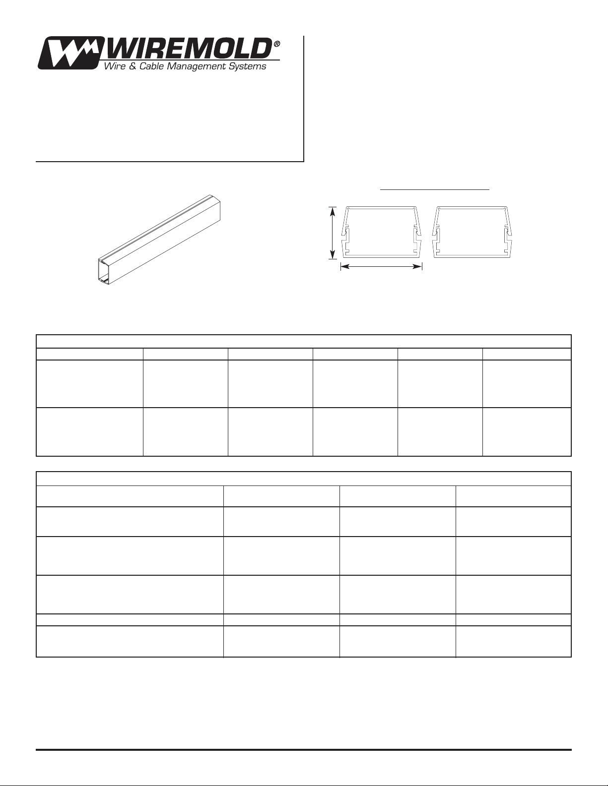
AL2400 Aluminum
Surface Raceway
INSTALLATION INSTRUCTIONS
Installation Instruction No.: INST007 R1 – Updated October 2003
AL2400 RACEWAY WIRE FILL CAPACITIES FOR POWER
WIRE TYPE TW THW RHH/RHW THHN/THWN
POWER WIRING 6 AWG 8 8 5 13
WITHOUT DEVICE 8 AWG 14 11 8 18
1.7 sq. in. cross section 10 AWG 31 22 15 37
12 AWG 40 27 24 58
14 AWG 50 33 30 78
POWER WIRING AWG 6 AWG 3
WITH DEVICE 8AWG 3 4
5-20R duplex devices 10 AWG 6 5 3 8
1.35 sq. in. cross section 12 AWG 8 6 5 12
14 AWG 10 7 6 16
NOTE:* 20% cable fill is calculated to approximate reduction in cable capacity due to connectors mounted within raceway and fittings that may restrict
cross sectional area.
** 40% cable fill is the maximum designed cable fill base on a proposed revision to TIA/EIA 569-A.
Wiremold Electrical Systems conform with, and should be installed and
properly grounded in compliance with requirement of the current
National Electrical Code or codes administered by local authorities.
All electrical products may represent a possible shock or fire hazard
if improperly installed or used. Wiremold electrical products are UL listed, made for interior use and should be installed by qualified
electrical people in conformance with current local and/or the
National Electrical Code.
Note: Raceway may be configured in single or multiple channels
to accommodate power or communications wiring.
MAXIMUM CROSS SECTION
Without Device
1.5 sq. in.
[38mm]
2"
[51mm]
1 9/32"
[33mm]
With 5-20R
1.35 sq. in.
[34mm]
Page 2
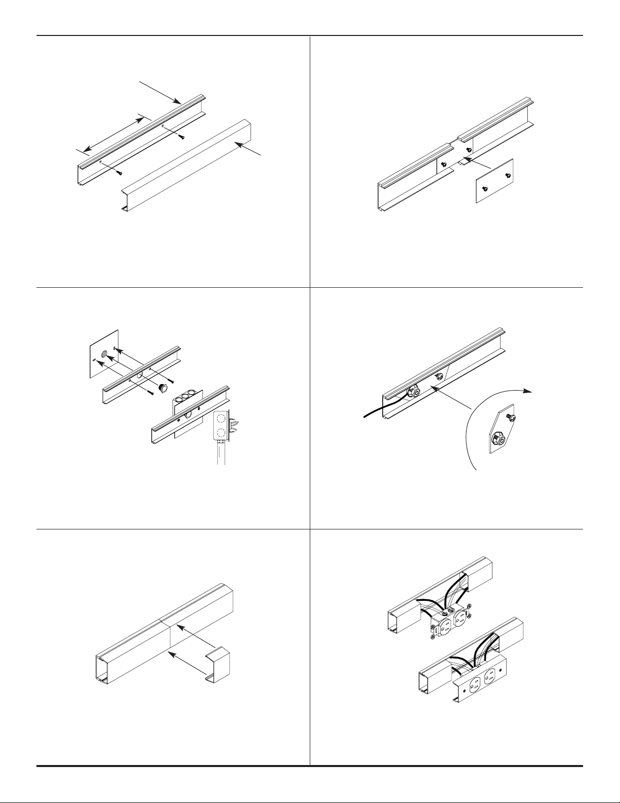
AL2400B BASE and AL2400C COVER
AL2401 COUPLING
AL2409 GROUND ADAPTER
AL2451H BOX ADAPTER
At AL2400B base section butt joints, slide AL2401 Coupling
into flathead first base section than slide next base to surface.
Center coupling on joint. Tighten locking screws.
To attach AL2400B base section to mounting surface, drill 9/32"
holes in the base (approx. 48" o/c.) fasten base with #8 head
screws. Snap AL2400C cover to complete installation.
Use for feed raceway from existing wall outlet box. To install,
attach adapter to outlet box with two screws. This system
is designed with capacity for additional feed or
circuitry conductors.
Position AL2409 Ground Clamp into rib in AL2400 raceway
base. Tighten locking screw. attach ground wire using
brass cup washer and green hex nut to ground lug.
AL2406 COVER CLIP AL2400P-D SERIES
To close any gaps at either the base or the cover that occur
from field cutting, Snap AL2406 Cover Clip over the joints
on the assembled raceway.
For AL2400P-D series duplex plates, Install wiring to devices
as required. Attach device to plate using #6 screws and
"Kep"nut (Provided) Snap device plate onto AL2400B
raceway base.
AL2400B
48" O.C. MAX
AL2400C
Page 3
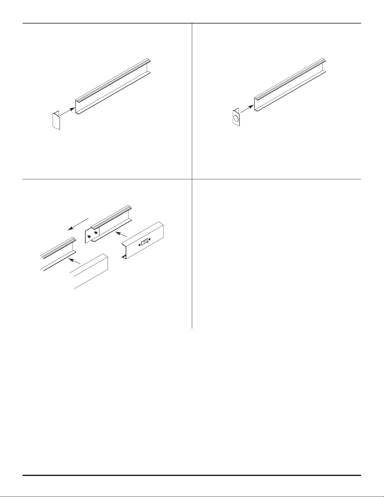
AL2410B BLANK END FITTING
AL2410B2 FEED END FITTING
AL2440A IN-LINE SINGLE POLE SWITCH
At end of AL2400B Raceway run, slide AL2410B2 Feed End
in last base section. Secure in place by tightening two #8-32
set screws. This system is designed with capacity for
additional feed or circuitry conductors.
At end of AL2400B raceway run, slide AL2410B Blank End
Fitting in last base section. Secure in place by tightening
two #8-32 screws.
Single Pole Switch 15A. 120V. To Install slide coupler into
groove of AL2400B raceway base and push base section
together. Tighten screws, connect all wires and snap in
cover to complete installation.
Page 4
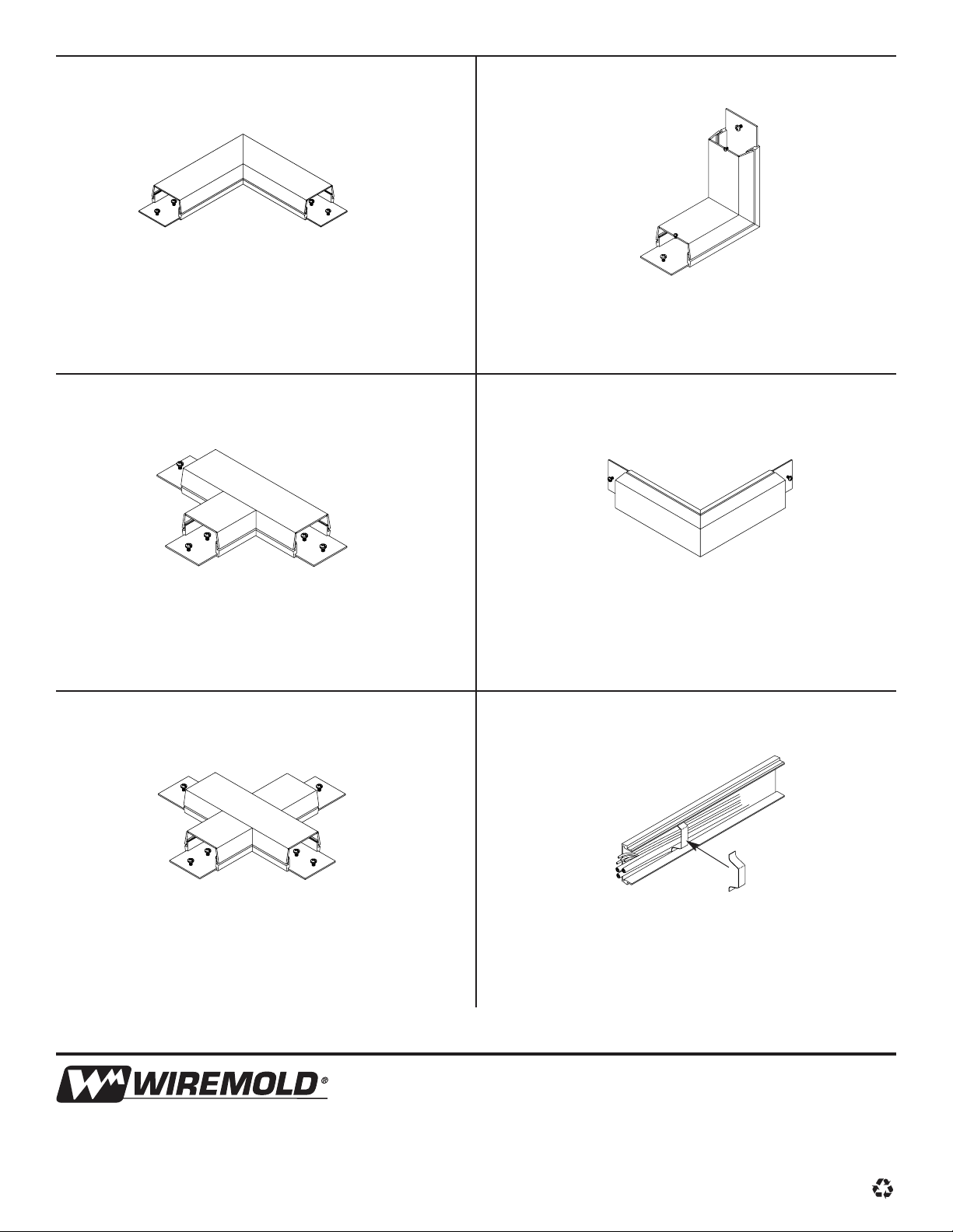
AL2411 90° FLAT ELBOW AL2417 INTERNAL ELBOW
AL2415 TEE ELBOW
AL2418 EXTERNAL ELBOW
AL2400WC WIRE CLIP
At 90° turn on same surface, position AL2411 Flat Elbow at
end of AL2400 base. Position next bases section onto other
end of AL2499B.Center couplings over base joints and
tighten screws. Install fitting cover after wiring.
Install AL2400 to raceway base BEFORE mounting raceway
base. Fasten base section to surface joints,tighten setscrews.
Center couplings over base joints and tighten screws.
Install fitting cover after wiring.
AL2415 tee fitting, position fitting at end of AL2400 base.
Install other base section to other end of fitting. Center
couplings on joints and tighten screws. Install fitting
cover after wiring.
At 90° outside corner, position AL2418 external elbow at end
of joints and tighten screws. Install fitting cover after wiring.
For retaining wires in long raceway run, Snap-in AL2400WC
Wire Clip approx. 30" apart into AL2400 base.
The Wiremold Company
U.S. and International:
60 Woodlawn Street • West Hartford, CT 06110
1-800-621-0049 • FAX 860-232-2062 • Outside U.S. 860-233-6251
INST007 R1 – Updated October 2003 – For latest specs visit www.wiremold.com
© Copyright 2003 The Wiremold Company All Rights Reserved
AL2416 CROSS ELBOW
AL2416 cross Elbow, position fitting at end of AL2400B base.
Install other base sections to other ends of the fitting. Center
Couplings on joints and tighten screws. Install cover fitting
after wiring.
 Loading...