


SM Series
Installation and Operation Manual
SPEEDMASTER
®
SM SERIES SUB-MICRO INVERTERS

TABLE OF CONTENTS
1.0 GENERAL . . . . . . . . . . . . . . . . . . . . . . . . . . . . . . . . . . . . . . . . . . . . .1
2.0 SM Series
™
DIMENSIONS . . . . . . . . . . . . . . . . . . . . . . . . . . . . . . . .3
4.0 SM Series
™
SPECIFICATIONS . . . . . . . . . . . . . . . . . . . . . . . . . . . . .4
5.0 SM Series
™
RATINGS . . . . . . . . . . . . . . . . . . . . . . . . . . . . . . . . . . . .5
6.0 INSTALLATION . . . . . . . . . . . . . . . . . . . . . . . . . . . . . . . . . . . . . . . .6
7.0 INPUT AC POWER REQUIREMENTS . . . . . . . . . . . . . . . . . . . . .7
8.0 POWER WIRING . . . . . . . . . . . . . . . . . . . . . . . . . . . . . . . . . . . . . . .9
9.0 SM Series
™
POWER WIRING DIAGRAM . . . . . . . . . . . . . . . . . . .11
10.0 CONTROL WIRING . . . . . . . . . . . . . . . . . . . . . . . . . . . . . . . . . . .12
11.0 SM Series
™
CONTROL WIRING DIAGRAMS . . . . . . . . . . . . . . .15
12.0 INITIAL POWER UP AND MOTOR ROTATION . . . . . . . . . . . .19
13.0 PROGRAMMING THE SM Series
™
DRIVE . . . . . . . . . . . . . . . . .21
14.0 PARAMETER MENU . . . . . . . . . . . . . . . . . . . . . . . . . . . . . . . . . . .25
15.0 DESCRIPTION OF PARAMETERS . . . . . . . . . . . . . . . . . . . . . . . .28
16.0 TROUBLESHOOTING . . . . . . . . . . . . . . . . . . . . . . . . . . . . . . . . .43
17.0 SM Series
™
DISPLAY MESSAGES . . . . . . . . . . . . . . . . . . . . . . . . .45
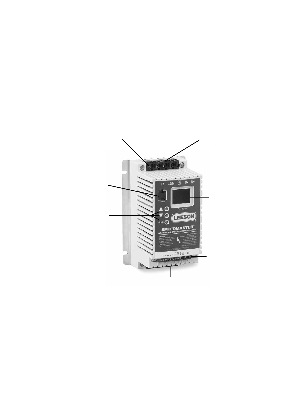
INPUT POWER
TERMINALS
ELECTRONIC
PROGRAMMING
MODULE (EPM)
PROGRAMMING
BUTTONS
OUTPUT (MOTOR)
TERMINALS
3-DIGIT LED
DISPLAY
CONTROL
TERMINAL
STRIP
DC BUS
TERMINALS
SUB-MICRO DRIVE
SPEEDMASTER
®
SM SERIES
™
LEESON Electric
IMPORTANT NOTICE
The following , and information is supplied to you for your
protection and to provide you with many years of trouble free and safe operation of your LEESON
Electric product.
• Hazard of electrical shock! Capacitors retain charge after power is removed. Disconnect incoming
power and wait until the voltage between terminals B+ and B- is 0 VDC before servicing the drive.
• Hazard of electrical shock! Wait three minutes after disconnecting incoming power before
servicing drive. Capacitors retain charge after power is removed.
• Automatic starting of equipment may cause damage to equipment and / or injury to personnel!
Automatic start should only be used on equipment that is inaccessible to personnel.
• DRIVES MUST NOT BE INSTALLED WHERE SUBJECTED TO ADVERSE ENVIRON-
MENTAL CONDITIONS SUCH AS: COMBUSTIBLE, OILY, OR HAZARDOUS VAPORS
OR DUST; EXCESSIVE MOISTURE OR DIRT; VIBRATION; EXCESSIVE AMBIENT
TEMPERATURES. CONSULT LEESON ELECTRIC FOR MORE INFORMATION ON
THE SUITABILITY OF A DRIVE TO A PARTICULAR ENVIRONMENT.
• Severe damage to the drive can result if it is operated after a long period of storage or inactivity
without reforming the DC bus capacitors!
• Do not connect incoming AC power to output terminals U, V, or W, or terminals B+, B-!.Severe
damage to the drive will result.
• When operating in JOG mode, the STOP signal and the AUXILIARY STOP function (see
Parameters 10-12), and the STOP key on the optional remote keypad WILL NO
T stop the drive.
To stop the drive, remove the JOG command.
• JOG REVERSE will operate the drive in reverse rotation even if ROTATION DIRECTION
(Parameter 17) is set to FORWARD ONLY.
• DO NOT connect incoming AC power to output terminals U, V, and W or terminals B+, B-!
Severe damage to the drive will result. Do not continuously cycle input power to the drive more
than once every two minutes. Damage to the drive will result.
• Do not remove the EPM while power is applied to the drive. Damage to the EPM and/or drive
may result.
• The availability of controllers is restricted according to EN 61800-3. These products can cause
radio interference in residential areas. In this case, special measures can be necessary.
• Consult qualified personnel with questions. All electrical repairs must be performed by trained
and qualified personnel only.
Resale of Goods:
In the event of the resale of any of the goods, in whatever form, Resellers/Buyers will include the following language in
a conspicuous place and in a conspicuous manner in a written agreement covering such sale:
The manufacturer makes no warranty or representations, express or implied, by operation of law or otherwise, as
the merchantability or fitness for a particular purpose of the goods sold hereunder. Buyer acknowledges that it
alone has determined that the goods purchased hereunder will suitably meet the requirements of their intended
use. In no event will the manufacturer be liable for consequential, incidental or other damages. Even if the repair
or replacement remedy shall be deemed to have failed of its essential purpose under Section 2-719 of the Uniform
Commercial Code, the manufacturer shall have no liability to Buyer for consequential damages.
Resellers/Buyers agree to also include this entire document including the warnings and cautions above in
a conspicuous place and in a conspicuous manner in writing to instruct users on the safe usage of the
product.
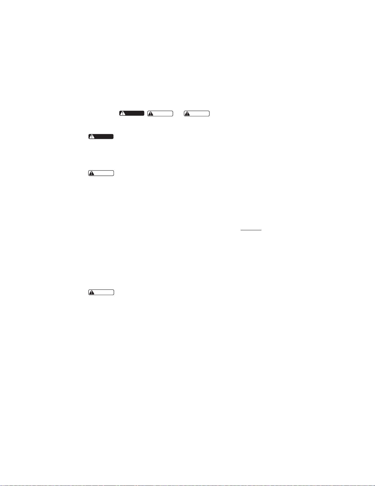
WARNING
WARNING
CAUTION
CAUTION
DANGER
DANGER

1.0 GENERAL
1.1 PRODUCTS COVERED IN THIS MANUAL
This manual covers the LEESON Electric SM Series
™
Variable Frequency Drive.
1.2 PRODUCT CHANGES
LEESON Electric reserves the right to discontinue or make modifications to the design of its products
without prior notice, and holds no obligation to make modifications to products sold previously.
LEESON Electric also holds no liability for losses of any kind which may result from this action.
Instruction manuals with the most up-to-date information are available for download from the LEESON
Electric website (www. leeson.com).
1.3 WARRANTY
LEESON Electric warrants the SM Series
™
AC motor control to be free of defects in material and
workmanship for a period of twelve months from the date of sale to the user, or eighteen months from
the date of shipment, which ever occurs first. If a SM Series
™
motor control, under normal use, becomes
defective within the stated warranty time period, contact LEESON Electric’s Service Department for
instructions on obtaining a warranty replacement unit. LEESON Electric reserves the right to make the
final determination as to the validity of a warranty claim, and sole obligation is to repair or replace only
components which have been rendered defective due to faulty material or workmanship. No warranty
claim will be accepted for components which have been damaged due to mishandling, improper instal-
lation, unauthorized repair and/or alteration of the product, operation in excess of design specifications
or other misuse, or improper maintenance. LEESON Electric makes no warranty that its products are
compatible with any other equipment, or to any specific application, to which they may be applied and
shall not be held liable for any other consequential damage or injury arising from the use of its products.
This warranty is in lieu of all other warranties, expressed or implied. No other person, firm or
corporation is authorized to assume, for LEESON Electric, any other liability in connection with
the demonstration or sale of its products.
NOTE 1: LEESON will match mode of transportation if drive is repaired under warranty.
Customer will be invoiced for shipping if no problem is found, if the repair is non-warranty, or if
the return mode is different.
NOTE 2: There is a minimum inspection fee of $100.00 if no problem is found. There is an
additional charge of 25% for Rush Service.
1.4 RECEIVING
Inspect all cartons for damage which may have occurred during shipping. Carefully unpack equipment
and inspect thoroughly for damage or shortage. Report any damage to carrier and/or shortages to
supplier. All major components and connections should be examined for damage and tightness, with
special attention given to PC boards, plugs, knobs and switches.
1

1.5 SAFETY INFORMATION
General
All operations concerning installation and commissioning, as well as maintenance, must be carried out
by qualified, skilled personnel (IEC 364 and CENELEC HD 384 or DIN VDE 0100 and IEC report
664 or DIN VDE 0110 and national regulations for the prevention of accidents must be observed).
According to this basic safety information, qualified skilled personnel are persons who are familiar with
the installation, assembly, commissioning, and operation of the product and who have the qualifications
necessary for their occupation.
APPLICATION AS DIRECTED
Drive controllers are components which are designed for installation in electrical systems or machinery.
They are not to be used as appliances. They are intended exclusively for professional and commercial
purposes according to EN 61000-3-2.
When installing the drive controllers in machines, commissioning (i.e. the starting of operation as
directed) is prohibited until it is proven that the machine complies with the regulations of the EC
Directive 98/37/EC (Machinery Directive); EN 60204 must be observed. Commissioning (i.e. starting
of operation as directed) is only allowed when there is compliance with the EMC Directive
(89/336/EEC).
The drive controllers meet the requirements of the Low Voltage Directive 73/23/EEC. The
harmonized standards of the series 61800-5-1 DIN/DIN VDE 0160 apply to the controllers.
NOTE: The availability of controllers is restricted according to EN 61800-3. These products can
cause radio interference in residential areas. In this case, special measures can be necessary.
ELECTRICAL CONNECTION
When working on live drive controllers, applicable national regulations for the prevention of accidents
(e.g. VBG 4) must be observed.
The electrical installation must be carried out according to the appropriate regulations (e.g. cable size,
fuses, PE connection).
This manual contains information about installation in compliance with EMC (shielding, grounding,
filters and cables). These notes must also be observed for CE-marked controllers. The manufacturer of
the system or machine is responsible for compliance with the required limit values demanded by EMC
legislation.
Suitable for use on a circuit capable of delivering not more than 5000 rms
symmetrical amperes, 240 V maximum (249 V devices) or 500 V maximum
(400/500 V devices) respectively.
Use minimum 75°C copper wire only.
Shall be installed in a pollution degree 2 macro-environment.
2
WARNING

1.6 CUSTOMER MODIFICATION
LEESON Electric welcome the opportunity to assist our customers in applying our products. Many
customizing options are available to aid in this function. LEESON Electric cannot assume responsibility
for any modifications not authorized by its engineering department.
3
4
HP INPUT INPUT SM
(kW) VOLTAGE PHASE MODEL H W D P R
0.33 120 1 174263 5.75 (146) 2.88 (74) 3.26 (83) 0.28 (7) 4.37 (111)
(0.25) 208/240 1 174267 5.75 (146) 2.88 (74) 3.26 (83) 0.28 (7) 4.37 (111)
120 1 174264 5.75 (146) 2.88 (74) 3.26 (83) 0.28 (7) 4.37 (111)
0.5 208/240 1 174268 5.75 (146) 2.88 (74) 3.26 (83) 0.28 (7) 4.37 (111)
(0.37) 208/240 3 174274 5.75 (146) 2.88 (74) 3.26 (83) 0.28 (7) 4.37 (111)
400/480 3 174281 5.75 (146) 2.88 (74) 3.94 (100) 0.80 (20) 4.37 (111)
120 1 174265 5.75 (146) 3.76 (95) 4.88 (124) 1.50 (38) 4.37 (111)
1 208/240 1 174270 5.75 (146) 2.88 (74) 3.63 (92) 0.63 (16) 4.37 (111)
(0.75) 208/240 3 174276 5.75 (146) 2.88 (74) 3.63 (92) 0.63 (16) 4.37 (111)
400/480 3 174282 5.75 (146) 2.88 (74) 4.74 (120) 1.60 (41) 4.37 (111)
120 1 174266 5.75 (146) 3.76 (95) 4.88 (124) 1.50 (38) 4.37 (111)
1.5 208/240 1 174271 5.75 (146) 3.76 (95) 4.88 (124) 1.50 (38) 4.37 (111)
(1.1) 208/240 3 174277 5.75 (146) 2.88 (74) 5.56 (141) 2.56 (65) 4.37 (111)
400/480 3 174283 5.75 (146) 2.88 (74) 5.74 (146) 2.56 (65) 4.37 (111)
2
208/240 1 174272 5.75 (146) 3.76 (95) 4.88 (124) 1.50 (38) 4.37 (111)
(1.5)
208/240 3 174278 5.75 (146) 2.88 (74) 5.56(141) 2.56 (65) 4.37 (111)
400/480 3 174284 5.75 (146) 2.88 (74) 5.74 (146) 2.56 (65) 4.37 (111)
3
208/240 1 174273 5.75 (146) 3.76 (95) 5.53 (140) 2.18 (55) 4.37 (111)
(2.2)
208/240 3 174279 5.75 (146) 3.76 (95) 5.53 (140) 2.18 (55) 4.37 (111)
400/480 3 174286 5.75 (146) 3.76 (95) 5.24 (133) 1.90 (48) 4.37 (111)
5 208/240 3 174288 5.75 (146) 3.76 (95) 6.74 (171) 3.40 (86) 3.25 (83)
(4.0) 400/480 3 174287 5.75 (146) 3.76 (95) 6.74 (171) 3.40 (86) 3.25 (83)
7.5 208/240 3 174280 7.75 (197) 5.02 (128) 7.18 (182) 3.40 (86) 4.81 (122)
(5.5) 400/480 3 174285 5.75 (146) 3.76 (95) 6.74 (171) 3.40 (86) 3.25 (83)
10 208/240 3 174290 7.75 (197) 5.02 (128) 7.18 (182) 3.40 (86) 4.81 (122)
(7.5) 400/480 3 174291 7.75 (197) 5.02 (128) 7.18 (182) 3.40 (86) 4.81 (122)
15 208/240 3 174292 9.75 (248) 6.68 (170) 8.00 (203) 3.40 (86) 6.30 (160)
(11) 400/480 3 174293 7.75 (197) 5.02 (128) 7.18 (182) 3.60 (91) 4.81 (122)
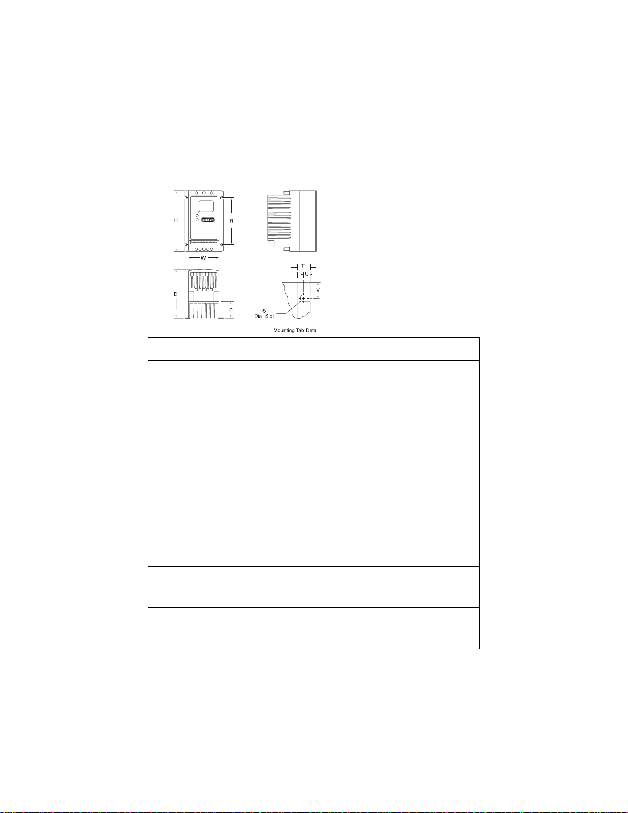
2.0 SM Series
™
DIMENSIONS
IF R < 6.30” (160)
S = 0.19” (5)
T = 0.38” (10)
U = 0.18” (5)
V = 0.66” (17)
IF R = 6.30” (160)
S = 0.28” (7)
T = 0.50” (13)
U = 0.24” (6)
V = 0.90” (23)

5
4.0 SM Series
™
SPECIFICATIONS
Storage Temperature -20° to 70° C
Ambient Operating Temperature 0° to 40° C (derate 2.5% per °C above 40°)
Ambient Humidity <95% (non-condensing)
Altitude 3300 ft (1000m) above sea level (derate 5% per additional 3300 ft)
Input Line Voltages 120, 208/240, 400/480 Vac
Input Voltage Tolerance +10%, -15%
Input Frequency Tolerance 48 to 62 Hz
Output Wave Form Sine Coded PWM
Output Frequency 0 - 240 Hz
Carrier Frequency 4 kHz to 10 kHz (10 kHz requires derating; see parameter P02)
Service Factor 1.00 (up to 8 kHz carrier, derate above 10 kHz; see parameter P02)
Efficiency Up to 98%
Power Factor (displacement) 0.96 or better
Overload Current Capacity 150% for 60 seconds, 180% for 30 seconds
Speed Reference Follower 0 - 10 VDC, 4 - 20 mA
Digital Outputs (1) Normally open relay; contacts rated 3 amps at 250 Vac
(1) Digital output (current-sourcing); rated 50 mA at 12 VDC
Earth Leakage Current (EN 50178) SCL: > 3.5 mA to PE SCM: < 3.5 mA to PE
Conformity CE: Low voltage directive (73/23/EEC)
Approvals UL 508C: Underwriters Laboratories - Po wer Conversion Equipment

6
5.0 SM Series
™
RATINGS
SM INPUT OUTPUT
MODEL FOR MOTORS 50-60 Hz) (3 Phase) HEAT LOSS
NUMBER RATED INPUT CURRENT POWER CURRENT (WATTS)
(NOTE 1) HP kW PHASE (AMPS) (kVA) (AMPS) (NOTE 1)
120 Vac INPUT MODELS 120 Vac 0 - 230 Vac
174263 0.33 0.25 1 6.8 0.8 1.7 29
174264 0.50 0.37 1 9.2 1.1 2.4 33
174265 1 0.75 1 16.6 2.0 4.2 57
174266 1.5 1.1 1 24 2.9 6.0 86
208/240 Vac INPUT MODELS 208/240 Vac 0 - 208/230 Vac
174267 0.33 0.25 1 3.9/3.4 0.8 1.9/1.7 23
174268 0.50 0.37 1 5.8/5.0 1.2 2.8/2.4 31
174274 0.50 0.37 3 3.1/2.7 1.1 2.8/2.4 31
174270 1 0.75 1 10.6/9.2 2.2 4.8/4.2 47
174276 1 0.75 3 5.8/5.1 2.1 4.8/4.2 47
174271 1.5 1.1 1 13.9/12.0 2.9 6.9/6.0 68
174277 1.5 1.1 3 8.0/6.9 2.9 6.9/6.0 68
174272 2 1.5 1 18.4/16.0 3.1 8.1/7.0 71
174278 2 1.5 3 9.1/7.9 3.3 8.1/7.0 71
174273 3 2.2 1 24/21 4.1 11.0/9.6 108
174279 3 2.2 3 12.4/10.8 4.5 11.0/9.6 108
174288 5 4.0 3 19.6/17.1 7.1 17.5/15.2 173
174280 7.5 5.5 3 28 / 25 10.3 25 / 22 286
174290 10 7.5 3 34 / 32 13.1 30 / 28 379
174292 15 11 3 54 / 48 20.0 48 / 42 476
400/480 Vac INPUT MODELS 400/480 Vac 0-400/460 Vac
174281 0.50 0.37 3 1.6/1.4 1.1 1.3/1.1 31
174282 1 0.75 3 3.0/2.5 2.1 2.5/2.1 47
174283 1.5 1.1 3 4.3/3.6 3.0 3.6/3.0 58
174284 2 1.5 3 4.8/4.0 3.3 4.1/3.4 63
174286 3 2.2 3 6.4/5.4 4.5 5.8/4.8 92
174287 5 4.0 3 10.6/8.8 7.1 9.4/7.8 155
174285 7.5 5.5 3 14.2 / 12.4 10.3 12.6 / 11.0 254
174291 10 7.5 3 18.1 / 15.8 13.1 16.1 / 14.0 310
174293 15 11 3 27 / 24 20.0 24 / 21 390
NOTE 1: Values are worst-case (not typical) for 6kHz carrier frequency at full speed and full load.

6.0 INSTALLATION
NOTE: SM Series
™
drives are intended for inclusion within other equipment, by professional
electrical installers according to EN 61000-3-2. They are not intended for stand-alone operation.
DRIVES MUST NOT BE INSTALLED WHERE SUBJECTED TO
ADVERSE ENVIRONMENTAL CONDITIONS SUCH AS:
COMBUSTIBLE, OILY, OR HAZARDOUS VAPORS OR DUST;
EXCESSIVE MOISTURE OR DIRT; VIBRATION; EXCESSIVE AMBIENT
TEMPERATURES. CONSULT LEESON ELECTRIC FOR MORE
INFORMATION ON THE SUITABILITY OF A DRIVE TO A PAR TICULAR
ENVIRONMENT.
SM Series
™
models are suitable for UL pollution degree 2 environment only, and MUST be installed in
an electrical enclosure which will provide complete mechanical protection and will maintain the internal
temperature within the drive’s ambient operating temperature rating. All drives models MUST be
mounted in a vertical position for proper heatsink cooling.
Maintain a minimum spacing around the drive of at least 1 inch (25mm) on each side and 2 inches
(50mm) on the top and bottom for units up to 5 HP (4 kW), and 2 inches (50 mm) on each side and 4
inches (100 mm) on the top and bottom for larger units. Allow more spacing if the drive is mounted next
to other heat-producing equipment. Do not mount drives above other drives or heat producing
equipment. Fans or blowers should be used to insure proper cooling in tight quarters.
In order to properly size an enclosure, the heat generated by the drive(s) must be known. Refer to the
HEAT LOSS columns in Section 5.0 - SM Series
™
RATINGS. An enclosure manufacturer can then
determine the required enclosure size based on the total heat generated inside the enclosure (from the
drive(s) and other heat sources), the maximum allowable temperature inside the enclosure, the maximum
ambient temperature outside the outside the enclosure, and the enclosure properties.
The SM Series
™
is UL approved for solid state motor overload protection. Therefore, a separate thermal
overload relay is not required for single motor applications.
6.1 INSTALLATION AFTER A LONG PERIOD OF STORAGE
Severe damage to the drive can result if it is operated after a long period of
storage or inactivity without reforming the DC bus capacitors!
If input power has not been applied to the drive for a period of time exceeding three years (due to
storage etc), the electrolytic DC bus capacitors within the drive can change internally, resulting in
excessive leakage current. This can result in pr emature failure of the capacitors if the drive is operated after
such a long period of inactivity or storage.
In order to reform the capacitors and prepare the drive for operation after a long period of inactivity,
apply input power to the drive for 8 hours prior to actually operating the motor.
7
WARNING
WARNING
8
7.0 INPUT AC POWER REQUIREMENTS
Hazard of electrical shock! Capacitors retain charge after power is removed.
Disconnect incoming power and wait until the voltage between terminals B+ and
B- is 0 VDC before servicing the drive.
The input voltage must match the nameplate voltage rating of the drive. Voltage fluctuation must not
vary by greater than 10% overvoltage or 15% undervoltage.
NOTE: Drives with dual input voltage ratings must be programmed for the proper supply
voltage (refer to Parameter 01 - LINE V OLTAGE SELECTION in Section 15.0 - DESCRIPTION
OF PARAMETERS).
The drive is suitable for use on a circuit capable of delivering not more than 5,000 RMS
symmetrical amperes at the drive’s rated voltage.
If the kVA rating of the AC supply transformer is greater than 10 times the input kVA rating of the
drive(s), an isolation transformer or 2-3% input line reactor must be added to the line side of the drive(s).
Three phase voltage imbalance must be less than 2.0% phase to phase. Excessive phase to phase
imbalance can cause severe damage to the drive’s power components.
Motor voltage should match line voltage in normal applications. The drive’s maximum output voltage
will equal the input voltage. Use extreme caution when using a motor with a voltage rating which is
different from the input line voltage.
7.1 INPUT VOLTAGE RATINGS
SM Series drives rated for 120 Vac, single phase, 50-60 Hz input will function with input voltage of 120
Vac (+10%, -15%), at 48 to 62 Hz.
SM Series drives rated for 208/240 Vac, single phase, 50-60 Hz input will function with input voltage of
208 to 240 Vac (+10%, -15%), at 48 to 62 Hz.
SM Series drives rated for 208/240 Vac, three phase, 50-60 Hz input will function with input voltage of
208 to 240 Vac (+10%, -15%), at 48 to 62 Hz.
SM Series drives rated for 400/480 Vac, three phase, 50-60 Hz input will function with input voltage of
400 to 480 Vac (+10%, -15%) at 48 to 62 Hz.
NOTE: Parameter 01 - LINE VOLTAGE SELECTION must be programmed according to the
applied input voltage. See Section 15.0 - DESCRIPTION OF PARAMETERS.
DANGER
9
7.2 INPUT FUSING AND DISCONNECT REQUIREMENTS
A circuit breaker or a disconnect switch with fuses must be provided in accordance with the National
Electric Code (NEC) and all local codes. Refer to the following tables for proper fuse/circuit breaker
ratings and wire sizes.
FUSE, CIRCUIT BREAKER, AND WIRE SIZES (for installation to UL and EN 60204-1)
NOTE 1: Use UL Class CC fast-acting, current limiting type fuses. Select fuses with low 1
2
T
values, rated at 200,000 AIC. Recommended fuses are Bussman KTK-R, JJN, and JJS. Similar fuses
with equivalent ratings by other manufacturers may also be acceptable.
NOTE 2: When using a pulse-current or universal-current sensitive ELCB (earth leakage circuit
breaker), the detection level must be rated 30mA or greater. Observe the following when using
ELCBs:
1. Only install the ELCB between the supply mains and drive controller.
2. The ELCB can be activated by:
- capacitive leakage currents between the cable screens during operation
(especially with long, screened motor cables)
- connecting several drives to the mains at the same time
- additional RFI filters
INPUT FUSE & CIRCUIT BREAKER RATINGS
120 Vac 1 phase 208/240 Vac 1 phase 208/240 Vac 3 phase 400/480 Vac 3 phase
174263 10A 174267 10A
174264 15A 174268 10A 174274 10A 174281 10A
174265 25A 174270 15A 174276 10A 174282 10A
174266 35A 174271 20A 174277 12/10A 174283 10A
174272 25/20A 174278 15/12A 174284 10A
174273 30/25A 174279 20/15A 174286 10A
174288 30/25A 174287 15/12A
174280 45/40A 174285 20/20A
174290 50/50A 174291 30/25A
174292 80/75A 174293 40/35A
INPUT WIRE SIZE REQUIREMENTS
120 Vac 1 phase 208/240 Vac 1 phase 208/240 Vac 3 phase 400/480 Vac 3 phase
MODEL AWG mm
2
MODEL AWG mm
2
MODEL AWG mm
2
MODEL AWG mm
2
174263 14 1.5 174267 14 1.5
174264 14 2.5 174268 14 1.5 174274 14 1.5 174281 14 1.5
174265 12 4.0 174270 14 2.5 174276 14 1.5 174282 14 1.5
174266 10 4.0 174271 14 2.5 174277 14 1.5 174283 14 1.5
174272 12 4.0 174278 14 2.5 174284 14 1.5
174273 10 4.0 174279 14 2.5 174286 14 1.5
174288 12 4.0 174287 14 2.5
174280 8 6.0 174285 12 2.5
174290 8 10 174291 10 4.0
174292 8 16 174293 8 6.0
10
7.3 INSTALLATION ACCORDING TO EMC REQUIREMENTS
The SM Series
™
Series can be installed to meet the European stan-
dards Electromagnetic Compatibility (EMC) requirements. These
requirements govern the permissible electromagnetic emissions and
immunity, both radiated and conducted, of a drive system.
The EMC requirements apply to the final installation in its entirety,
not to the individual components used. Because every installation is
different, the recommended installation should follow these guidelines
as a minimum. Additional equipment (such as ferrite core absorbers
on power conductors) or alternative wiring practices may be required
to meet conformance in some installations.
Filter: The input to the drive (or group of drives) must include a filter
to reduce the electrical noise reflected back to the AC Line.
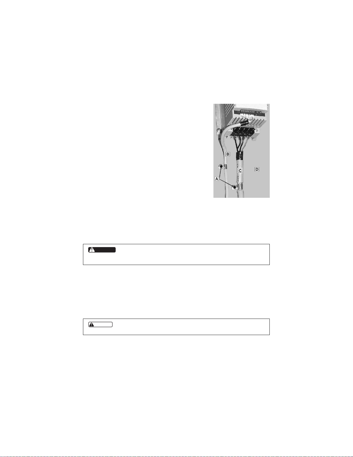
Installation: Shielded cable must be used for all control and power
cables and exposed wiring must be kept as short as possible. The
figure to the right shows the control cable (B) and motor cable (C)
with the shield grounded with clamps (A) to a grounded, electrically conductive mounting panel (D).
The motor cable must be of a low capacitance specification:
core / core ≤ 75 pF/m, core/shield ≤ 150 pF/m
8.0 POWER WIRING
Hazard of electrical shock! Capacitors retain charge after power is removed.
Disconnect incoming power and wait until the voltage between terminals B+ and
B- is 0 VDC before servicing the drive.
Note drive input and output current ratings and check applicable electrical codes for required wire type
and size, grounding requirements, over-current protection, and incoming power disconnect, before
wiring the drive. Size conservatively to minimize voltage drop.
Input fusing and a power disconnect switch or contactor MUST be wired in series with terminals L1 and
L2/N (on single-phase input models), or terminals L1, L2, and L3 (on three-phase input models). This
disconnect must be used to power down the drive when servicing, or when the drive is not to be operated
for a long period of time, but should not be used to start and stop the motor.
Repetitive cycling of a disconnect or input contactor (more than once every
two minutes) may cause damage to the drive.
DANGER
CAUTION

8.1 INPUT AND OUTPUT WIRING
On single phase input models, wire the input power to terminals L1 and L2/N. On three phase input
models, wire the input power to terminals L1, L2, and L3. Refer to Section 9.0 - SM Series
™
POWER
WIRING DIAGRAM.
All three power output wires, from terminals U, V, and W to the motor, must be kept tightly bundled
and run in a separate conduit away from all other power and control wiring.
It is not recommended to install contactors or disconnect switches between the drive and motor.
Operating such devices while the drive is running can potentially cause damage to the drive’s power
components. If such a device is required, it should only be operated when the drive is in a STOP state.
If there is potential for the device to be opened while the drive is running, the drive must be programmed
for COAST to stop (see Parameter 4 - STOP METHOD), and an auxiliar y contact on the device must
be interlocked with the drive’s run circuit. This will give the drive a stop command at the same time the
device opens, and will not allow the drive to start again until the device is closed.
11
12
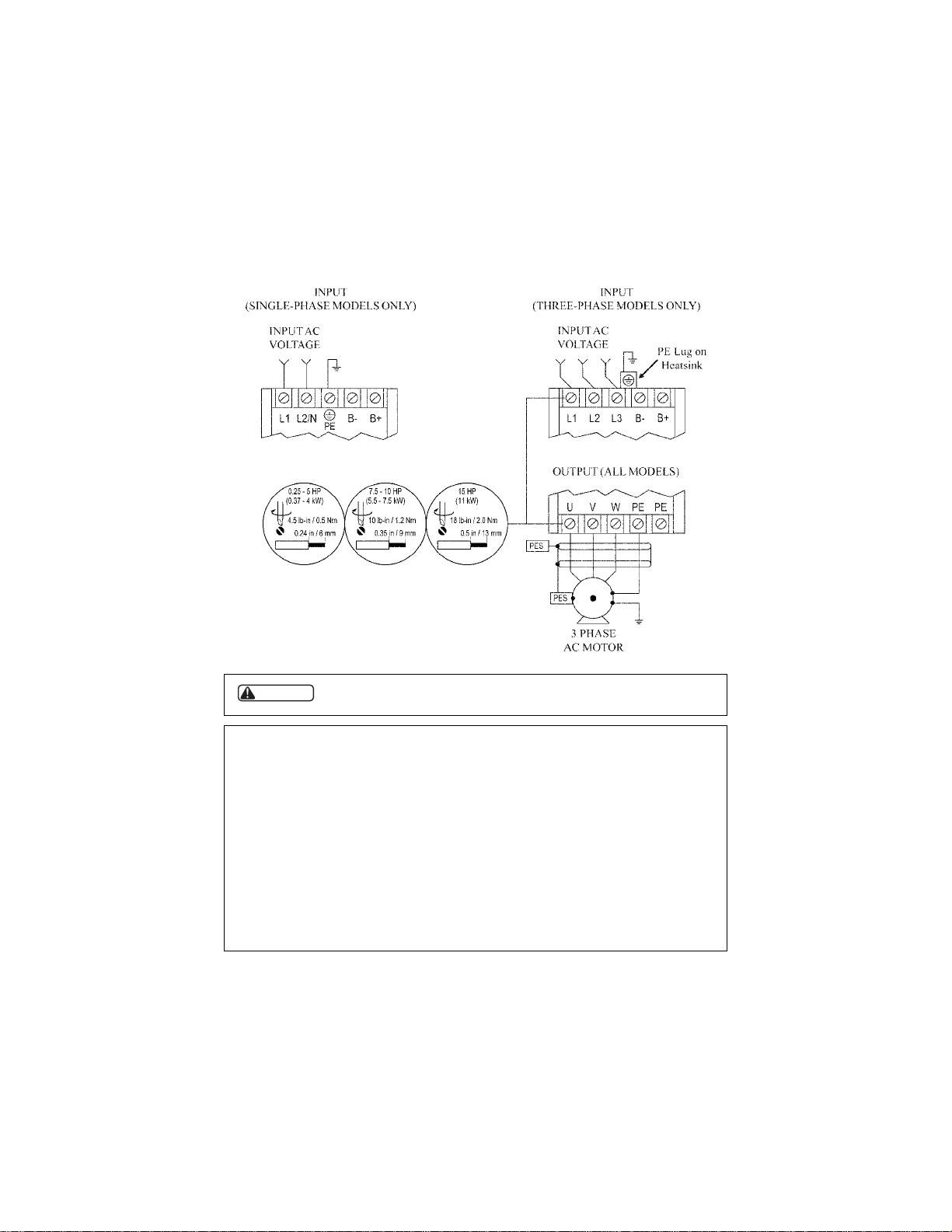
Do not connect incoming AC power to output terminals U, V, or W, or
terminals B+, B-!. Severe damage to the drive will result.
NOTES:
1. WIRE AND GROUND IN ACCORDANCE WITH NEC OR CEC, AND ALL
APPLICABLE LOCAL CODES.
2. Motor wires MUST be run in a separate steel conduit away from control wiring and incoming
AC power wiring.
3. Do not install contactors between the drive and the motor without consulting LEESON
Electric for more information. Failure to do so may result in drive damage.
4. Use only UL and CSA listed and approved wire.
5. Minimum wire voltage rating is 300 V for 120, 208, and 240 Vac systems and 600 V for 400
and 480 Vac systems.
6. Wire gauge must be based on a minimum of 125% of the rated input/output current of the
drive, and a minimum 75° C insulation rating. Use copper wire only.
9.0 SM Series
™
POWER WIRING DIAGRAM
WARNING

10.0 CONTROL WIRING
10.1 CONTROL WIRING VS. POWER WIRING
External control wiring MUST be run in a separate conduit away from all other input and output power
wiring. If control wiring is not kept separate from power wiring, electrical noise may be generated on the
control wiring that will cause erratic drive behavior. Use twisted wires or shielded cable grounded at the
drive chassis ONLY. Recommended control wire is Belden 8760 (2-wire) or 8770 (3-wire), or equivalent.
Strip off 0.20 to 0.25 inches (5 to 6 mm) of insulation for control wiring, and torque the control
terminals to 2 lb-in (0.2 Nm). Be careful not to overtorque the control terminals, as this will cause
damage to the terminal strip. This is not covered under warranty and can only be repaired by replacing
the control board.
10.2 TB-2: CIRCUIT COMMON
The TB-2 terminal is used as circuit common for the analog speed reference inputs. If necessary TB-2
may be connected to chassis ground.
10.3 SURGE SUPPRESSION ON RELAYS
Current and voltage surges and spikes in the coils of contactors, relays, solenoids, etc, near or connected
to the drive, can cause erratic drive operation. Therefore, a snubber circuit should be used on coils
associated with the drive. For AC coils, snubbers should consist of a resistor and a capacitor in series
across the coil. For DC coils, a free-wheeling or flyback diode should be placed across the coil. Snubbers
are typically available from the manufacturer of the device.
10.4 START/STOP CONTROL
There are various control schemes that allow for 2-wire and 3-wire S tart/Stop cir cuits. Refer to the wiring
diagrams in Section 11.0 - SM Series
™
CONTROL WIRING DIAGRAMS.
10.5 SPEED REFERENCE SIGNALS
The drive allows for three analog speed reference inputs:
SPEED POT Connect the wiper of a speed pot to terminal TB-5, and connect the high and low end
leads to terminals TB-6 and TB-2, respectively. The speed pot can be 2.5kΩ up to
10kΩ.
0-10 VDC Wire the positive to terminal TB-5 and the negative to terminal TB-2. TB-5 input
impedance is 120 kilohms.
4-20 mA Wire the positive to terminal TB-25 and the negative to terminal TB-2. TB-25 input
impedance is 250 ohms.
13
 Loading...