


SPEEDMASTER®
Series Compact
Installation
Operation Manual
A Regal Brand
TABLE OF CONTENTS |
|
|
1.0 |
GENERAL . . . . . . . . . . . . . . . . . . . . . . . . . . . . . . . . . . . . . . . . . . . . . . . . . . . . . . . . . . |
4 |
|
PRODUCT CHANGES . . . . . . . . . . . . . . . . . . . . . . . . . . . . . . . . . . . . . . . |
. . . . . . . . |
|
WARRANTY . . . . . . . . . . . . . . . . . . . . . . . . . . . . . . . . . . . . . . . . . . . . . . . . . . . . . . . . |
4 |
|
RECEIVING . . . . . . . . . . . . . . . . . . . . . . . . . . . . . . . . . . . . . . . . . . . . . . . . |
. . . . . . . . |
|
CUSTOMER MODIFICATION . . . . . . . . . . . . . . . . . . . . . . . . . . . . . . . . . . . |
. . . . . 4 |
2.0 |
MICRO SERIES SPECIFICATIONS . . . . . . . . . . . . . . . . . . . . . . . . . . . . . . . . . . . . . |
5 |
4.0 |
MICRO SERIES DIMENSIONS . . . . . . . . . . . . . . . . . . . . . . . . . . . . . . . . . . . . . . . . |
6 |
5.0 |
MICRO SERIES RATINGS . . . . . . . . . . . . . . . . . . . . . . . . . . . . . . . . . . . . . . . . . . . . |
13 |
6.0 |
THEORY . . . . . . . . . . . . . . . . . . . . . . . . . . . . . . . . . . . . . . . . . . . . . . . . . . . . . . . . . . . |
17 |
|
DESCRIPTION OF AC MOTOR OPERATION . . . . . . . . . . . . . . . . . . . . . . . . . . . |
17 |
|
DRIVE FUNCTION DESCRIPTION . . . . . . . . . . . . . . . . . . . . . . . . . . . . . . . . . . . . |
19 |
7.0 |
INSTALLATION . . . . . . . . . . . . . . . . . . . . . . . . . . . . . . . . . . . . . . . . . . . . . . . . . . . . . |
22 |
8.0 |
INPUT AC REQUIREMENTS. . . . . . . . . . . . . . . . . . . . . . . . . . . . . . . . . . . . . . . . . . |
24 |
9.0 |
VOLTAGE SELECTION . . . . . . . . . . . . . . . . . . . . . . . . . . . . . . . . . . . . . . . . |
. . . . . . 2 |
10.0 |
POWER WIRING . . . . . . . . . . . . . . . . . . . . . . . . . . . . . . . . . . . . . . . . . . . . . . . . . . . . |
25 |
11.0 |
MICRO SERIES POWER WIRING DIAGRAM . . . . . . . . . . . . . . . . . . . . . . . . |
. . . 26 |
12.0 |
INITIAL POWER UP . . . . . . . . . . . . . . . . . . . . . . . . . . . . . . . . . . . . . . . . . . . . . . . . . |
27 |
13.0 |
KEYPAD CONTROL . . . . . . . . . . . . . . . . . . . . . . . . . . . . . . . . . . . . . . . . . . . . . . . . . |
28 |
|
KEYPAD FUNCTIONS . . . . . . . . . . . . . . . . . . . . . . . . . . . . . . . . . . . . . . . . |
. . . . . . . |
|
MICRO SERIES DISPLAY . . . . . . . . . . . . . . . . . . . . . . . . . . . . . . . . . . . . . . . . . . . . . |
29 |
14.0 |
CONTROL WIRING . . . . . . . . . . . . . . . . . . . . . . . . . . . . . . . . . . . . . . . . . . . . . . . . . |
34 |
|
GENERAL . . . . . . . . . . . . . . . . . . . . . . . . . . . . . . . . . . . . . . . . . . . . . . . . . . . . . . . . . . |
34 |
|
START/STOP AND SPEED CONTROL . . . . . . . . . . . . . . . . . . . . . . . . . . |
. . . . . . . |
15.0 |
MICRO SERIES CONTROL WIRING DIAGRAMS . . . . . . . . . . . . . . . . . . . . . . . . |
40 |
|
MICRO SERIES TERMINAL STRIP . . . . . . . . . . . . . . . . . . . . . . . . . . . . . . . . . . . . . |
40 |
|
TWO-WIRE START/STOP CONTROL . . . . . . . . . . . . . . . . . . . . . . . . . . . . . . . . . . |
41 |
|
THREE-WIRE START/STOP CONTROL . . . . . . . . . . . . . . . . . . . . . . . . . . . . . . . . |
42 |
|
SPEED POT AND PRESET SPEED CONTROL . . . . . . . . . . . . . . . . . . . . . . . . . . . |
43 |
16.0 |
PROGRAMMING THE MICRO SERIES DRIVE . . . . . . . . . . . . . . . . . . . . . . . . . . |
44 |
|
PROGRAMMING THE PARAMETERS . . . . . . . . . . . . . . . . . . . . . . . . . . . . . . . . . . |
44 |
|
PARAMETER ACCESS USING SPEED DIAL . . . . . . . . . . . . . . . . . . . . . . . . . . |
. . . 46 |
17.0 |
PARAMETER MENU . . . . . . . . . . . . . . . . . . . . . . . . . . . . . . . . . . . . . . . . . . . . . . . . . |
47 |
18.0 |
DESCRIPTION OF PARAMETERS . . . . . . . . . . . . . . . . . . . . . . . . . . . . . . . . . . . . . |
51 |
1
TABLE OF CONTENTS (cont’d.)
19.0MICRO SERIES PID SET POINT CONTROL . . . . . . . . . . . . . . 77
FEEDBACK DEVICES .. .. .. .. .. .. .. .. .. .. .. .. .. .. .. .. .. .. .. .. .. .. .. .. .. .. .. .. .. .. .. .. .. .. .. .. .. .. .. .. .. .. .. .. .. .. .. .. |
77 |
THE SYSTEM - DIRECT AND REVERSE ACTING . . . . . . . . . . . . . . . . . . . . . . . . |
78 |
PID CONTROL - DIRECT AND REVERSE ACTING .. .. .. .. .. .. .. .. .. .. .. .. .. .. .. .. .. .. .. .. .. .. |
78 |
SET POINT REFERENCE SOURCES . . . . . . . . . . . . . . . . . . . . . . . . . . |
. . . . . . . . . |
TUNING THE PID CONTROL . . . . . . . . . . . . . . . . . . . . . . . . . . . . . . . . . . . . . . . . |
79 |
MICRO SERIES DISPLAY IN PID MODE . . . . . . . . . . . . . . . . . . . . . . . . . . . . . . . . |
80 |
20.0TROUBLESHOOTING . . . . . . . . . . . . . . . . . . . . . . . 81
21.0 |
USER SETTING RECORD . . . . . . . . . . . . . . . . . . . . . . 83 |
NOTE!
The manual covers software version M108314 and above.
See parameter 63 for the software version of the drive you are working with.
If you are working with an earlier software release, you will not have all of the functionality described in this manual, but the functionality of the drive is fulled documented in this manual.
If you are working with M108313 or earlier, parameters 69 and 70 are described in this manual as parameters 98 and 99.
2
IMPORTANT NOTICE
The following  DANGER ,
  WARNING and
  CAUTION information is supplied to you for your protection and to provide you with many years of trouble free and safe operation of your LEESON Electric product..
 DANGER
 WARNING
 CAUTION
• Hazard of electrical shock! Capacitors retain charge after power is removed. Disconnect incoming power and wait until the voltage between terminals B+ and B- is 0 VDC before servicing the drive..
• Hazard of electrical shock! Wait three minutes after disconnecting incoming power before servicing drive.. Capacitors retain charge after power is removed..
• Automatic starting of equipment may cause damage to equipment and / or injury to personnel! Automatic start should only be used on equipment that is inaccessible to personnel.
• DRIVES MUST NOT BE INSTALLED WHERE SUBJECTED TO ADVERSE
ENVIRONMENTAL CONDITIONS SUCH AS: COMBUSTIBLE, OILY, OR HAZARDOUS VAPORS OR DUST; EXCESSIVE MOISTURE OR DIRT; VIBRATION; EXCESSIVE AMBIENT TEMPERATURES. . CONSULT LEESON ELECTRIC FOR MORE INFORMATION ON THE SUITABILITY OF A DRIVE TO A PARTICULAR ENVIRONMENT..
•Severe damage to the drive can result if it is operated after a long period of storage or inactivity without reforming the DC bus capacitors!
•Do not connect incoming AC power to output terminals T1, T2, or T3. Severe damage to the drive will result..
•When operating in JOG mode, the STOP key WILL NOT stop the drive.. To stop the drive, the contact between TB-13B and TB-2 must be opened..
•Do not continuously cycle input power to the drive more than once every two minutes. Damage to the drive will result..
•The availability of controllers is restricted according to EN 61800-3. These products can cause radio interference in residential areas.. In this case, special measures can be necessary..
•Consult qualified personnel with questions. All electrical repairs must be performed by trained and qualified personnel only.
Resale of Goods:
In the event of the resale of any of the goods, in whatever form, Resellers/Buyers will include the following language in a conspicuous place and in a conspicuous manner in a written agreement covering such sale:
The manufacturer makes no warranty or representations, express or implied, by operation of law or otherwise, as the merchantability or fitness for a particular purpose of the goods sold hereunder. Buyer acknowledges that it alone has determined that the goods purchased hereunder will suitably meet the requirements of their intended use. In no event will the manufacturer be liable for consequential, incidental or other damages.
Even if the repair or replacement remedy shall be deemed to have failed of its essential purpose under Section
2-719 of the Uniform Commercial Code, the manufacturer shall have no liability to Buyer for consequential damages..
Resellers/Buyers agree to also include this entire document including the warnings and cautions above in a conspicuous place and in a conspicuous manner in writing to instruct users on the safe usage of the product..
3
1.0GENERAL
1.1This manual covers the LEESON MICRO Series Inverters..
1.2PRODUCT CHANGES
LEESON Electric reserves the right to discontinue or make modifications to the design of its products without prior notice, and holds no obligation to make modifications to products sold previously. LEESON Electric also holds no liability for losses of any kind which may result from this action.
1.3WARRANTY
LEESON Electric warrants the SPEEDMASTER MICRO Series AC motor control to be free of defects in material and workmanship for a period of twelve months from the date of sale to the user, or two years from the date of manufacture, which ever occurs first. . Any control component, which under normal use, becomes defective, within the stated warranty time period shall be returned to LEESON Electric, freight prepaid, for examination. Contact Leeson’s Warranty Dept. for a return authorization number and shipping instructions. LEESON Electric reserves the right to make the final determination as to the validity of a warranty claim, and sole obligation is to repair or replace only components which have been rendered defective due to faulty material or workmanship. No warranty claim will be accepted for components which have been damaged due to mishandling, improper installation, unauthorized repair and/or alteration of the product, operation in excess of design specifications or other misuse, or improper maintenance. LEESON Electric makes no warranty that its products are compatible with any other equipment, or to any specific application, to which they may be applied and shall not be held liable for any other consequential damage or injury arising from the use of its products.
This warranty is in lieu of all other warranties, expressed or implied. No other person, firm or corporation is authorized to assume, for LEESON Electric, any other liability in connection with the demonstration or sale of its products.
NOTE 1: LEESON will match mode of transportation if drive is repaired under warranty. . Customer will be invoiced for shipping if no problem is found, if the repair is non-warranty, or if the return mode is different..
NOTE 2: There is a minimum inspection fee of $100..00 if no problem is found.. There is an additional charge of 25% for Rush Service..
1.4RECEIVING
Inspect all cartons for damage which may have occurred during shipping. Carefully unpack equipment and inspect thoroughly for damage or shortage.. Report any damage to carrier and/or shortages to supplier.. All major components and connections should be examined for damage and tightness, with special attention given to PC boards, plugs, knobs and switches.
1.5CUSTOMER MODIFICATION
LEESON Electric, its sales representatives and distributors, welcome the opportunity to assist our customers in applying our product. . LEESON Electric cannot assume responsibility for any modifications not authorized by its engineering department.
4
2.0MICRO SERIES SPECIFICATIONS
Storage Temperature
Ambient Operating Temperature
(With 2.5 and 8 kHZ carrier, derate for higher carriers)
Ambient Humidity
Maximum Altitude
Input Line Voltages
Input Voltage Tolerance
Input Frequency Tolerance
Output Wave Form
Output Frequency
Carrier Frequency
Frequency Stability
Service Factor
Efficiency
Power Factor (Displacement)
Overload Current Capacity
Speed Reference Follower
Control Voltage
Analog Outputs
Digital Outputs
-20° to 70° C |
|
Chassis |
-10° to 55° C |
Type 1 (IP 31) |
-10° to 50° C |
Type 4 (IP 65) |
-10° to 40° C |
Type 12 (IP 54) |
-10° to 40° C |
Less than 95%
(non-condensing)
3300 feet (1000 meters) above sea level
240/120 Vac, 240/200 Vac,
480/400 Vac, and 590/480 Vac
+10%, -15%
48 to 62 Hz
Sine Coded PWM
0-120 Hz, Optional up to 1000 Hz
2.5 kHz to 14 kHz
+/-0.00006%/ C
1..00
>97% throughout speed range
>0.96
150% of drive output rating for one minute
180% of drive output rating for 30 seconds
0-10 VDC, or 4-20 mA
15 VDC
0 - 10 VDC, or 2 - 10 VDC Proportional to speed or load
Form C relay: 2 A at 28 VDC or 120 Vac
Open-collector outputs: 40 mA at 30 VDC
5
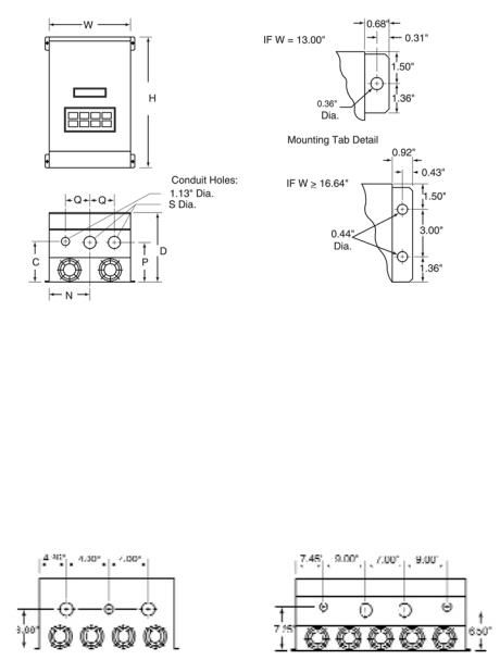
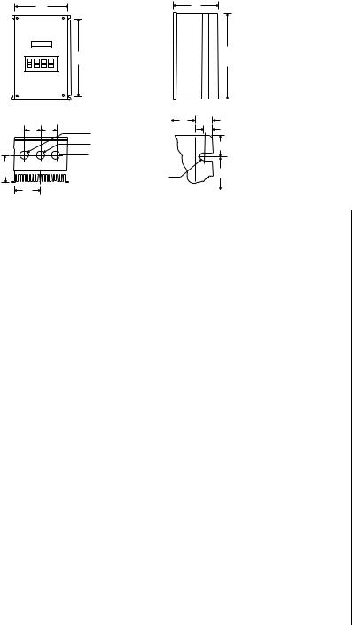
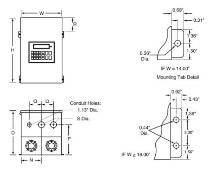
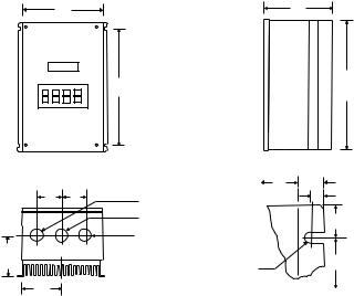
4.0MICRO SERIES DIMENSIONS
4.1TYPE 1 ENCLOSED
W D
R H
Q Q |
Conduit Holes: |
W |
U |
IF W ≤ 7.86" |
S Dia. |
|
V |
||
|
0.88" Dia. |
|
|
T = 0.20" |
|
|
1.00" |
U = 0.34" |
|
|
S Dia. |
|
||
P |
|
|
V = 0.19" |
|
|
|
|
IF W ≥ 10.26" |
|
|
|
|
R |
|
N |
|
T |
T = 0.28" |
|
|
|
|||
|
|
Dia. Slot |
|
U = 0.44" |
|
|
Mounting Tab Detail |
V = 0.24" |
|
|
|
|
||
HP |
INPUT |
CATALOG |
|
|
|
|
|
|
|
|
|
|
|
|
|
|
|
(kW) |
VOLTAGE |
NUMBER |
H |
|
W |
D |
|
N |
P |
Q |
|
R |
|
S |
|
|
|
|
|
|
|
|
|
|
|
|
|
|
|
|
|
|
|
|
|
0. .25 |
240/120 |
174930 |
7. |
.50 |
4. |
.70 |
3. |
.33 |
2. |
.35 |
1. |
.60 |
|
1. |
.37 |
5 |
|
(0.18) |
|
||||||||||||||||
|
|
|
|
|
|
|
|
|
|
|
|
|
|
|
|
|
|
0. .5 240/120 |
174997 |
7. |
.50 |
6. |
.12 |
3. |
.63 |
3. |
.77 |
1. |
.80 |
|
1. |
.37 |
5 |
||
(0.37) |
240/200 |
174914 |
7.50 |
|
4.70 |
3.63 |
|
2.35 |
1.90 |
1.37 |
|
5.50 |
|
0.88 |
|
|
|
1 |
240/120 |
174931 |
7. |
.50 |
6. |
.12 |
4. |
.22 |
3. |
.77 |
2. |
.40 |
|
1. |
.37 |
5 |
|
(0.75) |
240/200 |
174915 |
7.50 |
|
4.70 |
4.33 |
|
2.35 |
2.60 |
1.37 |
|
5.50 |
|
0.88 |
|
|
|
|
480/400 |
174920 |
7. |
.50 |
4. |
.70 |
3. |
.63 |
2. |
.35 |
1. |
.90 |
|
1. |
.37 |
5 |
|
|
|
|
|
|
|
|
|
|
|
|
|
|
|
|
|
|
|
|
590 |
174925 |
7. |
.50 |
4. |
.70 |
3. |
.63 |
2. |
.35 |
1. |
.90 |
|
1. |
.37 |
5 |
|
|
|
|
|
|
|
|
|
|
|
|
|
|
|
|
|
|
|
1. .5 240/120 |
174932 |
7. |
.50 |
6. |
.12 |
4. |
.22 |
3. |
.77 |
2. |
.40 |
|
1. |
.37 |
5 |
||
(1.1) |
240/200 |
174916 |
7.50 |
|
4.70 |
4.33 |
|
2.35 |
2.60 |
1.37 |
|
5.50 |
|
0.88 |
|
|
|
2 |
240 |
174933 |
7. |
.50 |
6. |
.12 |
5. |
.12 |
3. |
.77 |
3. |
.30 |
|
1. |
.37 |
5 |
|
(1.5) |
240/200 |
174917 |
7.50 |
|
6.12 |
5.12 |
|
3.77 |
3.30 |
1.37 |
|
5.50 |
|
0.88 |
|
|
|
|
480/400 |
174921 |
7. |
.50 |
6. |
.12 |
4. |
.22 |
3. |
.77 |
2. |
.40 |
|
1. |
.37 |
5 |
|
|
|
|
|
|
|
|
|
|
|
|
|
|
|
|
|
|
|
|
590 |
174926 |
7. |
.50 |
6. |
.12 |
4. |
.22 |
3. |
.77 |
2. |
.40 |
|
1. |
.37 |
5 |
|
|
|
|
|
|
|
|
|
|
|
|
|
|
|
|
|
|
|
3 |
240 |
174934 |
7. |
.50 |
6. |
.12 |
5. |
.12 |
3. |
.77 |
3. |
.30 |
|
1. |
.37 |
5 |
|
(2.2) |
240/200 |
174918 |
7.50 |
|
6.12 |
5.12 |
|
3.77 |
3.30 |
1.37 |
|
5.50 |
|
0.88 |
|
|
|
|
480/400 |
174922 |
7. |
.50 |
6. |
.12 |
5. |
.12 |
3. |
.77 |
3. |
.30 |
|
1. |
.37 |
5 |
|
|
|
|
|
|
|
|
|
|
|
|
|
|
|
|
|
|
|
|
590 |
174927 |
7. |
.50 |
6. |
.12 |
5. |
.12 |
3. |
.77 |
3. |
.30 |
|
1. |
.37 |
5 |
|
|
|
|
|
|
|
|
|
|
|
|
|
|
|
|
|
|
|
5 |
240/200 |
174919 |
7. |
.88 |
7. |
.86 |
5. |
.94 |
5. |
.13 |
3. |
.95 |
|
1. |
.50 |
5 |
|
(4) |
480/400 |
174923 |
7.50 |
|
6.12 |
5.12 |
|
3.77 |
3.30 |
1.37 |
|
5.50 |
|
0.88 |
|
|
|
|
590 |
174928 |
7. |
.50 |
6. |
.12 |
5. |
.12 |
3. |
.77 |
3. |
5.30 |
.5 |
01.. |
.88.37 |
|
|
|
|
|
|
|
|
|
|
|
|
|
|
|
|
|
|
|
|
6
W D
R H
|
|
Conduit Holes: |
W |
U |
IF W ʺ 7.86" |
Q |
Q |
|
V |
||
S Dia. |
|
||||
|
|
|
|
T = 0.20" |
|
|
|
0.88" Dia. |
|
1.00" |
U = 0.34" |
|
|
S Dia. |
|
|
V = 0.19" |
P |
|
|
|
R |
IF W ʺ 10.26" |
|
|
|
T |
T = 0.28" |
|
|
|
|
|
||
N |
|
|
Dia. Slot |
|
U = 0.44" |
|
|
Mounting Tab Detail |
V = 0.24" |
||
|
|
|
|||
|
|
|
|
||
HP |
INPUT |
CATALOG |
|
|
|
|
|
|
|
|
|
|
|
|
|
|
|
|
(kW) |
VOLTAGE |
NUMBER |
H |
|
W |
D |
N |
|
P |
|
Q |
|
R |
|
S |
|
|
|
7. .5 240/200 |
174545 |
7. |
.88 |
7. |
.86 |
5. |
.95 |
5. |
.13 |
3. |
.95 |
|
1. |
.80 |
5 |
|||
(5.5) |
480/400 |
174924 |
7.88 |
|
7.86 |
5.94 |
5.13 |
3.95 |
|
1.50 |
|
5.88 |
|
1.13 |
|
|
|
|
|
590 |
174929 |
7. |
.88 |
7. |
.86 |
5. |
.94 |
5. |
.13 |
3. |
.95 |
|
1. |
.50 |
5 |
||
10 |
240/200 |
174551 |
11. .257. .86 |
6. |
.84 |
3. |
.93 |
4. |
.19 |
2. |
.00 |
|
|
7. |
||||
(7.5) |
480/400 |
174552 |
9.38 |
|
7.86 |
6.84 |
3.93 |
4.19 |
|
2.00 |
|
5.88 |
|
1.13 |
|
|
|
|
|
590 |
174553 |
9. |
.38 |
7. |
.86 |
6. |
.84 |
3. |
.93 |
4. |
.19 |
|
2. |
.00 |
5 |
||
15 |
240/200 |
174557 |
12. .757. .86 |
6. |
.84 |
3. |
.93 |
4. |
.19 |
2. |
.00 |
|
|
9. |
||||
(11) |
480/400 |
174558 |
11.25 |
|
7.86 |
6.84 |
3.93 |
4.19 |
|
2.00 |
|
7.75 |
|
1.38 |
|
|
|
|
|
590 |
174559 |
12. .757. .86 |
6. |
.84 |
3. |
.93 |
4. |
.19 |
2. |
.00 |
|
|
9. |
||||
20 |
240/200 |
174560 |
12. .7510. .267. |
.74 |
5. |
.13 |
5. |
.00 |
2. |
|
.50 |
9. |
|
.25 |
||||
(15) |
480/400 |
174561 |
12.75 |
|
7.86 |
6.84 |
3.93 |
4.19 |
|
2.00 |
|
9.25 |
|
1.38 |
|
|
|
|
|
590 |
174562 |
12. .757. .86 |
7. |
.40 |
3. |
.93 |
4. |
.19 |
2. |
.00 |
|
|
9. |
||||
25 |
240/200 |
174569 |
15. .7510. .26 |
8. |
.35. .13 |
5. |
.00 |
2. |
.50 |
12. |
|
.25 |
1. |
|
.38 |
|||
(18.5) |
480/400 |
174563 |
12.75 |
|
10.26 |
7.74 |
5.13 |
5.00 |
|
2.50 |
|
9.25 |
|
1.38 |
|
|
|
|
|
590 |
174564 |
12. .7510. .267. |
.74 |
5. |
.13 |
5. |
.00 |
2. |
|
.50 |
9. |
|
.25 |
||||
30 |
240/200 |
174571 |
15. .7510. .26 |
8. |
.35. .13 |
5. |
.00 |
2. |
.50 |
12. |
|
.25 |
1. |
|
.38 |
|||
(22) |
480/400 |
174565 |
12.75 |
|
10.26 |
7.74 |
5.13 |
5.00 |
|
2.50 |
|
9.25 |
|
1.38 |
|
|
|
|
|
590 |
174598 |
15. .7510. .26 |
7. |
.745. |
.13 |
5. |
.00 |
2. |
.50 |
12. |
|
.25 |
1. |
|
.38 |
||
40 |
480/400 |
174567 |
12. .7510. .268. |
.35 |
5. |
.13 |
5. |
.00 |
2. |
|
.50 |
9. |
|
.25 |
||||
(30) |
590 |
174599 |
15.75 |
|
10.26 |
8.35 |
5.13 |
5.00 |
|
2.50 |
|
12.25 |
|
1.38 |
|
|
|
|
50 |
480/400 |
174593 |
19. .7510. .26 |
8. |
.55. .13 |
5. |
.75 |
2. |
.50 |
16. |
|
.25 |
1. |
|
.75 |
|||
(37) |
590 |
174594 |
19.75 |
|
10.26 |
8.55 |
5.13 |
5.75 |
|
2.50 |
|
16.25 |
|
1.75 |
|
|
|
|
60 |
480/400 |
174572 |
19. .7510. .26 |
8. |
.55. .13 |
5. |
.75 |
2. |
.50 |
16. |
|
.25 |
1. |
|
.75 |
|||
(45) |
590 |
174573 |
19.75 |
|
10.26 |
8.55 |
5.13 |
5.75 |
|
2.50 |
|
16.25 |
|
1.75 |
|
|
|
|
7
4.2TYPE 1 DIMENSIONS FOR MODELS RATED ABOVE 30 HP AT 240/200 Vac and 60 HP at 590/480/400 Vac
HP |
INPUT |
|
H |
|
W |
D |
|
N |
|
C |
P |
|
Q |
|
|
S |
|
|
(kW) |
VOLTAGE |
MODEL |
|
|
|
|
|
|
|
|
||||||||
40/30 |
240 / 200 |
174576 |
25. .0013. |
.0010. .505. |
.56 |
6. |
.50 |
6. |
|
.50 |
|
2. |
. |
62 |
||||
60/45 |
240 / 200 |
174578 |
47..00 |
16..64 |
11..85 |
|
|
See below |
|
|
|
|
|
|
||||
75/55 |
480 / 400 |
174580 |
29. .0016. |
.6411. |
.857. |
.14 |
6. |
.88 |
6. |
|
.88 |
|
3. |
. |
12 |
|||
100/75 |
480 / 400 |
174582 |
29. |
.00 |
24. |
.42 |
11. |
.85 |
117. . .12.25 |
6. |
.50 |
4. |
.50 |
2. |
|
.50 |
|
|
125/90 |
480 / 400 |
174584 |
29. |
.00 |
24. |
.42 |
11. |
.85 |
117. . .12.25 |
6. |
.50 |
4. |
.50 |
2. |
|
.50 |
|
|
150/110 |
480 / 400 |
174586 |
29..00 |
36..66 |
11..85 |
|
|
See below |
|
|
|
|
|
|
||||
CONDUIT HOLES FOR 174578 |
|
|
|
|
|
CONDUIT HOLES FOR 174586 |
|
|
|
|||||||||
Conduit Holes: Large holes = 1.75” |
Conduit Holes: Large holes = 3.00” |
Small holes = 1.13” |
Small holes = 1.13” |
8
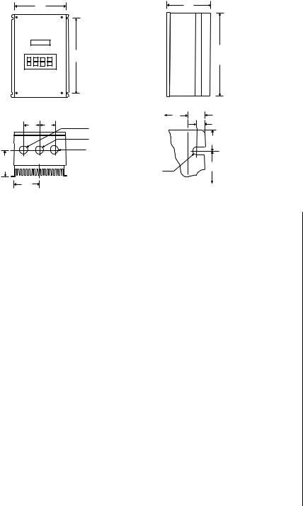
4.3WASHGUARD NEMA 4/12, 12, & 4X
W D
R H
|
|
|
Q |
Q |
Conduit Holes: |
|
|
W |
|
U |
|
IF W ʺ 7.86" |
|
|
|
|
|
||
|
|
|
S Dia. |
|
|
|
|
|
V |
|
|
|
|
|
|
||||
|
|
|
|
|
|
|
|
|
|
|
|
T = 0.20" |
|
|
|
|
|
||
|
|
|
|
|
0.88" Dia. |
|
|
|
|
|
|
|
|
|
|
|
|||
|
|
|
|
|
|
|
|
|
1.00" |
U = 0.34" |
|
|
|
|
|
||||
|
|
|
|
|
S Dia. |
|
|
|
|
|
|
|
V = 0.19" |
|
|
|
|
|
|
|
P |
|
|
|
|
|
|
|
|
|
R |
|
IF W ʺ 10.26" |
|
|
|
|
|
|
|
|
|
|
|
|
|
|
T |
|
|
|
T = 0.28" |
|
|
|
|
|
||
|
|
|
|
|
|
|
|
|
|
|
|
|
|
|
|
|
|||
|
|
|
N |
|
|
|
Dia. Slot |
|
|
|
U = 0.44" |
|
|
|
|
|
|||
|
|
|
|
|
|
|
|
Mounting Tab Detail |
|
V = 0.24" |
|
|
|
|
|
||||
|
|
|
|
|
|
|
|
|
|
|
|
|
|
|
|||||
|
|
|
|
|
|
|
|
|
|
|
|
|
|
|
|
|
|||
|
|
|
|
|
|
|
|
|
|
|
|
|
|
|
|
|
|
|
|
HP |
|
|
INPUT |
CATALOG |
|
|
|
|
|
|
|
|
|
|
|
|
|
|
|
(kW) |
|
VOLTAGE |
NUMBER |
H |
W |
|
D |
|
N |
P |
Q |
|
R |
S |
|
|
|
||
0. |
.25 |
240/120 |
174996 |
7. |
.88 |
6. |
.12 |
3. |
.63 |
3. |
.06 |
2. |
.00 |
1. |
.37 |
5 |
|||
(0.18) |
|
|
|
174519** |
|||||||||||||||
|
|
|
|
|
|
|
|
|
|
|
|
|
|
|
|
|
|||
0. |
|
.5 |
240/120 |
174998 |
7. |
.88 |
7. |
.86 |
3. |
.75 |
4. |
.80 |
2. |
.10 |
1. |
.37 |
5 |
||
(0.37) |
|
|
|
174520** |
|||||||||||||||
|
|
|
|
|
|
|
|
|
|
|
|
|
|
|
|
|
|||
|
|
240/200 |
174935 |
7. |
.88 |
6. |
.12 |
4. |
.35 |
3. |
.06 |
2. |
.70 |
1. |
.37 |
5 |
|||
|
|
|
|
|
174527** |
||||||||||||||
|
|
|
|
|
|
|
|
|
|
|
|
|
|
|
|
|
|
|
|
1 |
|
240/120 |
174999 |
7. |
.88 |
7. |
.86 |
3. |
.75 |
4. |
.80 |
3. |
.25 |
1. |
.37 |
5 |
|||
(0.75) |
|
|
|
174521** |
|||||||||||||||
|
|
|
|
|
|
|
|
|
|
|
|
|
|
|
|
|
|||
|
|
240/200 |
174936 |
7. |
.88 |
6. |
.12 |
4. |
.35 |
3. |
.06 |
2. |
.70 |
1. |
.37 |
5 |
|||
|
|
|
|
|
174528** |
||||||||||||||
|
|
|
|
|
|
|
|
|
|
|
|
|
|
|
|
|
|
|
|
|
|
480/400 |
174939 |
7. |
.88 |
6. |
.12 |
4. |
.35 |
3. |
.06 |
2. |
.70 |
1. |
.37 |
5 |
|||
|
|
|
|
|
174532** |
||||||||||||||
|
|
|
|
|
|
|
|
|
|
|
|
|
|
|
|
|
|
|
|
|
|
590 |
|
174943 |
7. |
.88 |
6. |
.12 |
4. |
.35 |
3. |
.06 |
2. |
.70 |
1. |
.37 |
5 |
||
|
|
|
|
|
174536** |
||||||||||||||
|
|
|
|
|
|
|
|
|
|
|
|
|
|
|
|
|
|
|
|
1. |
.5 |
240/120 |
174515 |
7. |
.88 |
7. |
.86 |
4. |
.90 |
4. |
.80 |
3. |
.25 |
1. |
.37 |
5 |
|||
(1.1) |
|
|
|
174517** |
|||||||||||||||
|
|
|
|
|
|
|
|
|
|
|
|
|
|
|
|
|
|||
|
|
240/200 |
174482 |
7. |
.88 |
6. |
.12 |
5. |
.25 |
3. |
.06 |
3. |
.60 |
1. |
.37 |
5 |
|||
|
|
|
|
|
174529** |
||||||||||||||
|
|
|
|
|
|
|
|
|
|
|
|
|
|
|
|
|
|
|
|
2 |
|
240 |
|
174475 |
7. |
.88 |
7. |
.86 |
4. |
.90 |
4. |
.80 |
3. |
.25 |
1. |
.37 |
5 |
||
(1.5) |
|
|
|
174525** |
|||||||||||||||
|
|
|
|
|
|
|
|
|
|
|
|
|
|
|
|
|
|||
|
|
240/200 |
174937 |
7. |
.88 |
7. |
.86 |
4. |
.90 |
4. |
.80 |
3. |
.25 |
1. |
.37 |
5 |
|||
|
|
|
|
|
174530** |
||||||||||||||
|
|
|
|
|
|
|
|
|
|
|
|
|
|
|
|
|
|
|
|
|
|
480/400 |
174940 |
7. |
.88 |
7. |
.86 |
4. |
.90 |
4. |
.80 |
3. |
.25 |
1. |
.37 |
5 |
|||
|
|
|
|
|
174533** |
||||||||||||||
|
|
|
|
|
|
|
|
|
|
|
|
|
|
|
|
|
|
|
|
|
|
590 |
|
174944 |
7. |
.88 |
7. |
.86 |
4. |
.90 |
4. |
.80 |
3. |
.25 |
1. |
.37 |
5 |
||
|
|
|
|
|
174537** |
||||||||||||||
|
|
|
|
|
|
|
|
|
|
|
|
|
|
|
|
|
|
|
|
|
|
|
|
|
|
|
|
|
|
|
|
|
|
|
|
|
|
|
|
*= NEMA 12 Only
**= NEMA 4X Others are NEMA 4/12
9
W D
R H
|
Q |
Q |
Conduit Holes: |
|
|
W |
U |
|
IF W ʺ 7.86" |
|
|
|
|
|
|||
|
S Dia. |
|
|
|
|
V |
|
|
|
|
|
|
|||||
|
|
|
|
|
|
|
|
|
T = 0.20" |
|
|
|
|
|
|||
|
|
|
0.88" Dia. |
|
|
|
1.00" |
U = 0.34" |
|
|
|
|
|
||||
|
|
|
S Dia. |
|
|
|
|
|
|
V = 0.19" |
|
|
|
|
|
||
|
P |
|
|
|
|
|
|
R |
|
IF W ʺ 10.26" |
|
|
|
|
|
||
|
|
|
|
|
T |
|
|
T = 0.28" |
|
|
|
|
|
||||
|
N |
|
|
|
Dia. Slot |
|
|
|
U = 0.44" |
|
|
|
|
|
|||
|
|
|
|
|
Mounting Tab Detail |
|
V = 0.24" |
|
|
|
|
|
|||||
|
|
|
|
|
|
|
|
|
|
|
|
||||||
|
|
|
|
|
|
|
|
|
|
|
|
|
|
|
|||
|
|
|
|
|
|
|
|
|
|
|
|
|
|
|
|
|
|
HP |
INPUT |
CATALOG |
|
|
|
|
|
|
|
|
|
|
|
|
|
|
|
(kW) |
VOLTAGE |
NUMBER |
H |
W |
|
D |
N |
P |
|
Q |
|
R |
S |
|
|
|
|
3 |
240 |
174729 |
7. |
.88 |
7. |
.86 |
5. |
.90 |
4. |
.80 |
4. |
.25 |
1. |
.37 |
5 |
||
(2.2) |
|
174526** |
|||||||||||||||
|
|
|
|
|
|
|
|
|
|
|
|
|
|
|
|
||
|
240/200 |
174938 |
7. |
.88 |
7. |
.86 |
5. |
.90 |
4. |
.80 |
4. |
.25 |
1. |
.37 |
5 |
||
|
|
174531** |
|||||||||||||||
|
|
|
|
|
|
|
|
|
|
|
|
|
|
|
|
|
|
|
480/400 |
174941 |
7. |
.88 |
7. |
.86 |
4. |
.90 |
4. |
.80 |
3. |
.25 |
1. |
.37 |
5 |
||
|
|
174534** |
|||||||||||||||
|
|
|
|
|
|
|
|
|
|
|
|
|
|
|
|
|
|
|
590 |
174945 |
7. |
.88 |
7. |
.86 |
4. |
.90 |
4. |
.80 |
3. |
.25 |
1. |
.37 |
5 |
||
|
|
174538** |
|||||||||||||||
|
|
|
|
|
|
|
|
|
|
|
|
|
|
|
|
|
|
5 |
240/200 |
174730 |
7. |
.88 |
7. |
.86 |
4. |
.90 |
4. |
.80 |
3. |
.25 |
1. |
.37 |
5 |
||
(4) |
|
174732** |
|||||||||||||||
|
|
|
|
|
|
|
|
|
|
|
|
|
|
|
|
||
|
480/400 |
174942 |
7. |
.88 |
7. |
.86 |
5. |
.90 |
4. |
.80 |
4. |
.25 |
1. |
.37 |
5 |
||
|
|
174535** |
|||||||||||||||
|
|
|
|
|
|
|
|
|
|
|
|
|
|
|
|
|
|
|
590 |
174946 |
7. |
.88 |
7. |
.86 |
5. |
.90 |
4. |
.80 |
4. |
.25 |
1. |
.37 |
5 |
||
|
|
174539** |
|||||||||||||||
|
|
|
|
|
|
|
|
|
|
|
|
|
|
|
|
|
|
7. .5 |
240/200 |
174734 |
11. .7510. .268. |
.35 |
5. |
.13 |
5. |
|
.75 |
2. |
.00 |
9. |
|
.75 |
|||
(5.5) |
|
174735** |
|
|
|||||||||||||
|
|
|
|
|
|
|
|
|
|
|
|
|
|
|
|
||
|
480/400 |
174548 |
8. .3810. .266. |
.90 |
5. |
.13 |
5. |
|
.25 |
2. |
.00 |
6. |
|
.38 |
|||
|
|
174745** |
|
|
|||||||||||||
|
|
|
|
|
|
|
|
|
|
|
|
|
|
|
|
|
|
|
590 |
174549 |
9. .7510. .267. |
.20 |
5. |
.13 |
5. |
|
.25 |
2. |
.00 |
7. |
|
.75 |
|||
|
|
174759** |
|
|
|||||||||||||
|
|
|
|
|
|
|
|
|
|
|
|
|
|
|
|
|
|
10 |
240/200 |
174737 |
13. .7510. |
.26 |
8. |
.35. |
.13 |
5. |
.75 |
2. |
.00 |
11. |
.75 |
1. |
|
.38 |
|
(7.5) |
|
174738** |
|
||||||||||||||
|
|
|
|
|
|
|
|
|
|
|
|
|
|
|
|
||
|
480/400 |
174554 |
11. .7510. .268. |
.35 |
5. |
.13 |
5. |
|
.75 |
2. |
.00 |
9. |
|
.75 |
|||
|
|
174747** |
|
|
|||||||||||||
|
|
|
|
|
|
|
|
|
|
|
|
|
|
|
|
|
|
|
590 |
174556 |
11. .7510. .268. |
.35 |
5. |
.13 |
5. |
|
.75 |
2. |
.00 |
9. |
|
.75 |
|||
|
|
174761** |
|
|
|||||||||||||
|
|
|
|
|
|
|
|
|
|
|
|
|
|
|
|
|
|
15 |
240/200 |
174740 |
15. .7510. |
.26 |
8. |
.35. |
.13 |
5. |
.75 |
2. |
.00 |
13. |
.75 |
1. |
|
.38 |
|
(11) |
|
174741** |
|
||||||||||||||
|
|
|
|
|
|
|
|
|
|
|
|
|
|
|
|
||
|
480/400 |
174749 |
13. .7510. |
.26 |
8. |
.35. |
.13 |
5. |
.75 |
2. |
.00 |
11. |
.75 |
1. |
|
.38 |
|
|
|
174750** |
|
||||||||||||||
|
|
|
|
|
|
|
|
|
|
|
|
|
|
|
|
|
|
|
590 |
174763 |
13. .7510. |
.26 |
8. |
.35. |
.13 |
5. |
.75 |
2. |
.00 |
11. |
.75 |
1. |
|
.38 |
|
|
|
174764** |
|
||||||||||||||
|
|
|
|
|
|
|
|
|
|
|
|
|
|
|
|
|
|
*= NEMA 12 Only
**= NEMA 4X Others are NEMA 4/12
10
4.4TYPE 12 DIMENSIONS FOR MODELS RATED ABOVE 30 HP AT 240/200 Vac AND 60 HP AT 590/480/400 Vac
HP |
INPUT |
|
|
|
|
|
|
|
|
|
|
|
|
|
|
|
(kW) |
VOLTAGE |
MODEL |
H |
|
W |
D |
|
N |
P |
Q |
|
R |
|
|
S |
|
75/55 |
480 / 400 |
174581 |
37. .0018. .0013. |
.307. |
.50 8. |
.00 |
|
3. |
.13 |
|
7. . |
14 |
||||
100/75 |
480 / 400 |
174583 |
39. |
.00 |
26. |
.00 |
13. |
.30 |
119. . .50.00 |
4. |
.50 |
9. |
.14 |
2. |
.50 |
|
125/90 |
480 / 400 |
174585 |
39. |
.00 |
26. |
.00 |
13. |
.30 |
119. . .50.00 |
4. |
.50 |
9. |
.14 |
2. |
.50 |
|
11
W D
R H
Q |
Q |
Conduit Holes: |
W |
U |
IF W ʺ 7.86" |
S Dia. |
|
V |
|||
|
|
|
|
T = 0.20" |
|
|
|
0.88" Dia. |
|
|
|
|
|
|
1.00" |
U = 0.34" |
|
|
|
S Dia. |
|
|
V = 0.19" |
P |
|
|
|
R |
IF W ʺ 10.26" |
|
|
T |
|
T = 0.28" |
|
|
|
|
|
||
N |
|
Dia. Slot |
|
|
U = 0.44" |
|
Mounting Tab Detail |
V = 0.24" |
|||
|
|
||||
|
|
|
|||
HP |
INPUT |
CATALOG |
|
|
|
|
|
|
|
|
|
|
|
|
|
|
(kW) |
VOLTAGE |
NUMBER |
H |
W |
|
D |
N |
|
P |
|
Q |
|
R |
S |
|
|
20 |
240/200 |
174743* |
15. |
.7510. |
.26 |
8. |
.35. |
.13 |
5. |
.75 |
2. |
.00 |
11. |
.75 |
1. |
.38 |
(15) |
480/400 |
174752 |
15. |
.7510. |
.26 |
8. |
.35. |
.13 |
5. |
.75 |
2. |
.00 |
11. |
.75 |
1. |
.38 |
|
|
174753** |
||||||||||||||
|
|
|
|
|
|
|
|
|
|
|
|
|
|
|
|
|
|
590 |
174766 |
15. |
.7510. |
.26 |
8. |
.35. |
.13 |
5. |
.75 |
2. |
.00 |
13. |
.75 |
1. |
.38 |
|
|
174767** |
||||||||||||||
|
|
|
|
|
|
|
|
|
|
|
|
|
|
|
|
|
25 |
240/200 |
174595* |
20. .2510. .26 |
8. |
.35. |
.13 |
5. |
.75 |
2. |
.00 |
16. |
.25 |
1. |
.38 |
||
(18.5) |
480/400 |
174755* |
15.75 |
10.26 |
|
8.35 |
5.13 |
|
5.75 |
|
2.00 |
|
11.75 |
1.38 |
|
.38 |
|
590 |
174769* |
15. .7510. .26 |
8. |
.35. |
.13 |
5. |
.75 |
2. |
.00 |
11. |
.75 |
1. |
|||
30 |
240/200 |
174596* |
20. .2510. .26 |
8. |
.35. |
.13 |
5. |
.75 |
2. |
.00 |
11. |
.75 |
1. |
.38 |
||
(22) |
480/400 |
174757* |
15.75 |
10.26 |
|
8.35 |
5.13 |
|
5.75 |
|
2.00 |
|
11.75 |
1.38 |
|
.38 |
|
590 |
174597* |
15. .7510. .26 |
8. |
.35. |
.13 |
5. |
.75 |
2. |
.00 |
11. |
.75 |
1. |
|||
40 |
480/400 |
174513* |
20. .2510. .26 |
8. |
.35. |
.13 |
5. |
.75 |
2. |
.00 |
16. |
.25 |
1. |
.38 |
||
(30) |
590 |
174512* |
20.25 |
10.26 |
|
8.35 |
5.13 |
|
5.75 |
|
2.00 |
|
16.25 |
1.38 |
|
|
50 |
480/400 |
174511* |
21. .0013. .72 |
8. |
.35. |
.13 |
6. |
.10 |
2. |
.00 |
16. |
.25 |
1. |
.38 |
||
(37) |
590 |
174510* |
21.00 |
13.72 |
|
8.35 |
5.13 |
|
6.10 |
|
2.00 |
|
16.25 |
1.38 |
|
|
60 |
480/400 |
174574* |
21. .0013. .72 |
8. |
.35. |
.13 |
6. |
.10 |
2. |
.00 |
16. |
.25 |
1. |
.38 |
||
(45) |
590 |
174575* |
21.00 |
13.72 |
|
8.35 |
5.13 |
|
6.10 |
|
2.00 |
|
16.25 |
1.38 |
|
|
*= NEMA 12 Only
**= NEMA 4X Others are NEMA 4/12
12

5.0MICRO SERIES RATINGS
115/230 & 230V (SINGLE PHASE) VOLT MICRO SERIES RATINGS
|
MODEL |
|
|
|
INPUT |
|
|
|
|
|
OUTPUT |
|
|||||
|
|
|
(120/240 Vac, 50-60 Hz) |
|
|
(0-230 Vac) |
|
||||||||||
|
|
|
|
|
|
|
|
|
|||||||||
|
|
|
|
|
|
|
NOMINAL |
|
|
|
|
|
|
|
|
||
|
FOR MOTORS |
|
CURRENT |
|
|
|
NOMINAL |
|
|
||||||||
CATALOG |
|
RATED |
|
|
INPUT |
(AMPS) |
|
|
POWER |
CURRENT |
POWER |
||||||
NUMBER |
HP |
|
kW |
PHASE |
(NOTE 1) |
|
|
(KVA) |
(AMPS) |
|
(KVA) |
||||||
174930 |
|
|
|
|
|
|
|
|
|
|
|
|
|
|
|
|
|
174996* |
0. |
.25 |
|
0. |
.18 |
1 |
6. |
.0/3. |
.0 |
|
0. |
.7 |
1. |
.4/1. |
.4 |
0. |
.6 |
174519** |
|
|
|
|
|
|
|
|
|
|
|
|
|
|
|
|
|
174997 |
|
|
|
|
|
|
|
|
|
|
|
|
|
|
|
|
|
174998* |
. |
.50 |
|
0. |
.37 |
1 |
9. |
.2/4. |
.6 |
|
1. |
.1 |
2. |
.2/2. |
.2 |
0. |
.9 |
174520** |
|
|
|
|
|
|
|
|
|
|
|
|
|
|
|
|
|
174391 |
|
|
|
|
|
|
|
|
|
|
|
|
|
|
|
|
|
174999* |
1 |
|
0. |
.75 |
1 |
16. |
.2/8. |
.1 |
|
1. |
.9 |
4. |
.0/4. |
.0 |
1. |
.6 |
|
174521** |
|
|
|
|
|
|
|
|
|
|
|
|
|
|
|
|
|
174932 |
|
|
|
|
|
|
|
|
|
|
|
|
|
|
|
|
|
174515* |
1. |
.5 |
|
1. |
.1 |
1 |
21. .0/10. .4 |
2. |
.5 |
5. |
.2/5. |
.2 |
2. |
.1 |
|||
174517** |
|
|
|
|
|
|
|
|
|
|
|
|
|
|
|
|
|
|
MODEL |
|
|
|
INPUT |
|
|
|
|
|
OUTPUT |
|
|||||
|
|
|
(200/240 Vac, 50-60 Hz) |
|
(0-200/230 Vac) |
||||||||||||
|
|
|
|
|
|
|
|||||||||||
|
|
|
|
|
|
|
|
|
|
|
|
|
|
|
|
|
|
174933 |
|
|
|
|
|
|
|
|
|
|
|
|
|
|
|
|
|
174475* |
2 |
|
1. |
.5 |
1 |
17. .1/14. . |
9 |
3. |
.6 |
7. |
.8/6. |
.8 |
2. |
.7 |
|||
174525** |
|
|
|
|
|
|
|
|
|
|
|
|
|
|
|
|
|
174934 |
|
|
|
|
|
|
|
|
|
|
|
|
|
|
|
|
|
174729* |
3 |
|
2. |
.2 |
1 |
24/21 |
|
|
5. |
.0 |
11. |
.0/9. |
.6 |
3. |
.8 |
||
174526** |
|
|
|
|
|
|
|
|
|
|
|
|
|
|
|
|
|
NOTE 1: For 115/230 Vac, the higher current rating is for 120 Vac input and the lower current rating is for 240 Vac input.. NOTE 2: See Section 8..0 for recommended fuse type..
*= NEMA 4/12 ENCLOSURE
**= NEMA 4X ENCLOSURE OTHERS ARE NEMA 1 ENCLOSURE
13

230 VOLT MICRO SERIES RATINGS
|
MODEL |
|
|
|
INPUT |
|
|
|
|
|
|
OUTPUT |
|
|||||
|
|
|
(200/240 Vac, 50-60 Hz) |
|
|
(0-200/230 Vac) |
||||||||||||
|
|
|
|
|
|
|
|
|||||||||||
|
FOR MOTORS |
|
NOMINAL |
|
|
|
NOMINAL |
|
|
|||||||||
CATALOG |
|
RATED |
|
|
INPUT |
CURRENT |
|
POWER |
CURRENT |
POWER |
||||||||
NUMBER |
HP |
|
kW |
PHASE |
(AMPS) |
|
|
(KVA) |
|
(AMPS) |
|
(KVA) |
||||||
174914 |
|
|
|
|
|
|
|
|
|
|
|
|
|
|
|
|
|
|
174935* |
. .50 |
|
0. |
.37 |
3 |
3. |
.1/2. |
.7 |
|
1. |
.1 |
|
2. |
.5/2. |
.2 |
0. |
.88 |
|
174527** |
|
|
|
|
|
|
|
|
|
|
|
|
|
|
|
|
|
|
174915 |
|
|
|
|
|
|
|
|
|
|
|
|
|
|
|
|
|
|
174936* |
1 |
|
|
0. |
.75 |
3 |
5. |
.5/4. |
.8 |
|
2. |
.0 |
|
4. |
.6/4. |
.0 |
1. |
.6 |
174528** |
|
|
|
|
|
|
|
|
|
|
|
|
|
|
|
|
|
|
174916 |
|
|
|
|
|
|
|
|
|
|
|
|
|
|
|
|
|
|
174482* |
1. |
.5 |
|
1. |
.1 |
3 |
7. |
.1/6. |
.2 |
|
2. |
.6 |
|
6. |
.0/5. |
.2 |
2. |
.1 |
174529** |
|
|
|
|
|
|
|
|
|
|
|
|
|
|
|
|
|
|
174917 |
|
|
|
|
|
|
|
|
|
|
|
|
|
|
|
|
|
|
174937* |
2 |
|
|
1. |
.5 |
3 |
9. |
.3/8. |
.1 |
|
3. |
.4 |
|
7. |
.8/6. |
.8 |
2. |
.7 |
174530** |
|
|
|
|
|
|
|
|
|
|
|
|
|
|
|
|
|
|
174918 |
|
|
|
|
|
|
|
|
|
|
|
|
|
|
|
|
|
|
174938* |
3 |
|
|
2. |
.2 |
3 |
13. .0/11. . |
3 |
4. |
.7 |
|
11. |
.0/9. |
.6 |
3. |
.8 |
||
174531** |
|
|
|
|
|
|
|
|
|
|
|
|
|
|
|
|
|
|
174919 |
|
|
|
|
|
|
|
|
|
|
|
|
|
|
|
|
|
|
174730* |
5 |
|
|
3. |
.7 |
3 |
20. .0/17. . |
7 |
7. |
.4 |
17. .5/15. .2 |
6. |
.1 |
|||||
174732** |
|
|
|
|
|
|
|
|
|
|
|
|
|
|
|
|
|
|
174545 |
|
|
|
|
|
|
|
|
|
|
|
|
|
|
|
|
|
|
174734* |
7. |
.5 |
|
5. |
.5 |
3 |
30/26 |
|
|
10. |
.6 |
|
25/22 |
|
8. |
.8 |
||
174735** |
|
|
|
|
|
|
|
|
|
|
|
|
|
|
|
|
|
|
174551 |
|
|
|
|
|
|
|
|
|
|
|
|
|
|
|
|
|
|
174737* |
10 |
|
|
7. |
.5 |
3 |
37/32 |
|
|
13. |
.2 |
|
32/28 |
|
11. |
.2 |
||
174738** |
|
|
|
|
|
|
|
|
|
|
|
|
|
|
|
|
|
|
174557 |
|
|
|
|
|
|
|
|
|
|
|
|
|
|
|
|
|
|
174740* |
15 |
|
|
11 |
3 |
55/48 |
|
|
19. |
.8 |
|
48/42 |
|
16. |
.7 |
|||
174741** |
|
|
|
|
|
|
|
|
|
|
|
|
|
|
|
|
|
|
174560 |
20 |
|
|
15 |
3 |
70/61 |
|
|
25. |
|
.3 |
62/54 |
|
21. |
|
|||
174743* |
|
|
|
|
|
|
|
|||||||||||
|
|
|
|
|
|
|
|
|
|
|
|
|
|
|
|
|
|
|
174569 |
25 |
|
|
18. |
|
.5 3 |
89/77 |
|
|
32. |
|
.0 |
78/68 |
|
27. |
|
||
174595* |
|
|
|
|
|
|
|
|
||||||||||
|
|
|
|
|
|
|
|
|
|
|
|
|
|
|
|
|
|
|
174571 |
30 |
|
|
22 |
3 |
104/90 |
|
|
37. |
|
.6 |
92/80 |
|
31. |
|
|||
174596* |
|
|
|
|
|
|
|
|||||||||||
|
|
|
|
|
|
|
|
|
|
|
|
|
|
|
|
|
|
|
174576 |
40 |
|
|
30 |
3 |
119/99 |
|
|
41. |
.0 |
|
120/104 |
|
41. |
.4 |
|||
174578 |
60 |
|
|
45 |
3 |
174/145 |
|
|
60. |
.5 |
|
177/154 |
|
61. |
.3 |
|||
.5
.1
.9
NOTE See Section 8..0 for recommended fuse type..
*= NEMA 4/12 or 12 ENCLOSURE
**= NEMA 4X ENCLOSURE OTHERS ARE NEMA 1 ENCLOSURE
14

|
|
|
|
460 VOLT MICRO SERIES RATINGS |
|
|
|
|
|
|
|
|
|||||
|
MODEL |
|
|
|
INPUT |
|
|
|
|
|
OUTPUT |
|
|
||||
|
|
|
(400/480 Vac, 50-60 Hz) |
|
|
|
(0-400/460 Vac) |
|
|||||||||
|
|
|
|
|
|
|
|
|
|||||||||
|
FOR MOTORS |
|
NOMINAL |
|
|
NOMINAL |
|
|
|
||||||||
CATALOG |
RATED |
|
|
INPUT |
CURRENT |
POWER |
CURRENT |
POWER |
|
||||||||
NUMBER |
HP |
|
kW |
PHASE |
(AMPS) |
|
(KVA) |
|
(AMPS) |
|
(KVA) |
|
|||||
174920 |
|
|
|
|
|
|
|
|
|
|
|
|
|
|
|
|
|
174939* |
1 |
|
0. |
.75 |
3 |
2. |
.8/2. |
.4 |
2. |
.0 |
|
2. |
.3/2. |
.0 |
1. |
.6 |
|
174532** |
|
|
|
|
|
|
|
|
|
|
|
|
|
|
|
|
|
174921 |
|
|
|
|
|
|
|
|
|
|
|
|
|
|
|
|
|
174940* |
2 |
|
1. |
.5 |
3 |
4. |
.7/4. |
.1 |
3. |
.4 |
|
3. |
.9/3. |
.4 |
2. |
.7 |
|
174533** |
|
|
|
|
|
|
|
|
|
|
|
|
|
|
|
|
|
174922 |
|
|
|
|
|
|
|
|
|
|
|
|
|
|
|
|
|
174941* |
3 |
|
2. |
.2 |
3 |
6. |
.8/5. |
.7 |
4. |
.7 |
|
5. |
.5/4. |
.8 |
3. |
.8 |
|
174534** |
|
|
|
|
|
|
|
|
|
|
|
|
|
|
|
|
|
174923 |
|
|
|
|
|
|
|
|
|
|
|
|
|
|
|
|
|
174942* |
5 |
|
3. |
.7 |
3 |
10. |
.2/8. |
.9 |
7. |
.3 |
|
8. |
.7/7. |
.6 |
6. |
.1 |
|
174535** |
|
|
|
|
|
|
|
|
|
|
|
|
|
|
|
|
|
174924 |
|
|
|
|
|
|
|
|
|
|
|
|
|
|
|
|
|
174548* |
7. .5 |
|
5. |
.5 |
3 |
14. .7/12. .8 |
10. |
.6 |
12. .6/11. .0 |
8. |
.8 |
|
|||||
174745** |
|
|
|
|
|
|
|
|
|
|
|
|
|
|
|
|
|
174552 |
|
|
|
|
|
|
|
|
|
|
|
|
|
|
|
|
|
174554* |
10 |
|
7. |
.5 |
3 |
18. .3/15. .9 |
13. |
.2 |
16. .0/14. .0 |
11. |
.2 |
|
|||||
174747** |
|
|
|
|
|
|
|
|
|
|
|
|
|
|
|
|
|
174558 |
|
|
|
|
|
|
|
|
|
|
|
|
|
|
|
|
|
174749* |
15 |
|
11 |
3 |
28/24 |
|
19. |
.8 |
|
24/21 |
|
16. |
.7 |
|
|||
174750** |
|
|
|
|
|
|
|
|
|
|
|
|
|
|
|
|
|
174561 |
|
|
|
|
|
|
|
|
|
|
|
|
|
|
|
|
|
174752* |
20 |
|
15 |
3 |
36/31 |
|
25. |
.3 |
|
31/27 |
|
21. |
.5 |
|
|||
174753** |
|
|
|
|
|
|
|
|
|
|
|
|
|
|
|
|
|
174563 |
25 |
|
18. |
|
.5 3 |
44/38 |
|
31. |
|
.9 |
39/34 |
|
27. |
|
.1 |
||
174755* |
|
|
|
|
|
|
|||||||||||
|
|
|
|
|
|
|
|
|
|
|
|
|
|
|
|
|
|
174565 |
30 |
|
22 |
3 |
52/45 |
|
37. |
|
.6 |
46/40 |
|
31. |
|
.9 |
|||
174757* |
|
|
|
|
|
||||||||||||
|
|
|
|
|
|
|
|
|
|
|
|
|
|
|
|
|
|
174567 |
40 |
|
30 |
3 |
68/59 |
|
49. |
|
.0 |
60/52 |
|
44. |
|
.0 |
|||
174513* |
|
|
|
|
|
||||||||||||
|
|
|
|
|
|
|
|
|
|
|
|
|
|
|
|
|
|
174593 |
50 |
|
37 |
3 |
85/74 |
|
61. |
|
.5 |
75/65 |
|
51. |
|
.8 |
|||
174511* |
|
|
|
|
|
||||||||||||
|
|
|
|
|
|
|
|
|
|
|
|
|
|
|
|
|
|
174572 |
60 |
|
45 |
3 |
100/87 |
|
72. |
|
.3 |
88/77 |
|
61. |
|
.3 |
|||
174574* |
|
|
|
|
|
||||||||||||
|
|
|
|
|
|
|
|
|
|
|
|
|
|
|
|
|
|
174580 |
75 |
|
55 |
3 |
109/91 |
|
75. |
|
.5 |
110/96 |
|
76. |
|
.5 |
|||
174581* |
|
|
|
|
|
||||||||||||
|
|
|
|
|
|
|
|
|
|
|
|
|
|
|
|
|
|
174582 |
100 |
|
75 |
3 |
139/116 |
|
96. |
|
.4 |
143/124 |
|
98. |
|
.8 |
|||
174583* |
|
|
|
|
|
||||||||||||
|
|
|
|
|
|
|
|
|
|
|
|
|
|
|
|
|
|
174584 |
125 |
|
90 |
3 |
175/146 |
|
121. |
|
.4 |
179/156 |
|
124. |
|
.3 |
|||
174585* |
|
|
|
|
|
||||||||||||
|
|
|
|
|
|
|
|
|
|
|
|
|
|
|
|
|
|
174586 |
150 |
|
110 |
3 |
202/168 |
|
139. |
.7 |
|
207/180 |
|
143. |
.4 |
|
|||
NOTE See Section 8..0 for recommended fuse type..
*= NEMA 4/12 or 12 ENCLOSURE
**= NEMA 4X ENCLOSURE OTHERS ARE NEMA 1 ENCLOSURE
15

575 VOLT MICRO SERIES RATINGS
|
MODEL |
|
INPUT |
|
OUTPUT |
|||
|
(480/590 Vac, 50-60 Hz) |
(0-460/575 Vac) |
||||||
|
|
|
|
|||||
|
FOR MOTORS |
|
NOMINAL |
|
NOMINAL |
|
||
CATALOG |
|
RATED |
INPUT |
CURRENT |
POWER |
CURRENT |
POWER |
|
NUMBER |
HP |
|
kW |
PHASE |
(AMPS) |
(KVA) |
(AMPS) |
(KVA) |
174925 |
|
|
|
|
|
|
|
|
174943* |
1 |
|
0..75 |
3 |
1..9 / 1..9 |
1..9 |
1..6 / 1..6 |
1..6 |
174536** |
|
|
|
|
|
|
|
|
174926 |
|
|
|
|
|
|
|
|
174944* |
2 |
|
1..5 |
3 |
3..3 / 3..3 |
3..4 |
2..7 / 2..7 |
2..7 |
174537** |
|
|
|
|
|
|
|
|
174927 |
|
|
|
|
|
|
|
|
174945* |
3 |
|
2..2 |
3 |
4..6 / 4..6 |
4..7 |
3..9 / 3..9 |
3..9 |
174538** |
|
|
|
|
|
|
|
|
174928 |
|
|
|
|
|
|
|
|
174946* |
5 |
|
3..7 |
3 |
7..1 / 7..1 |
7..3 |
6..1 / 6..1 |
6..1 |
174539** |
|
|
|
|
|
|
|
|
174929 |
|
|
|
|
|
|
|
|
174549* |
7..5 |
|
5..5 |
3 |
10..5 / 10..5 |
10..7 |
9..0 / 9..0 |
8..8 |
174759** |
|
|
|
|
|
|
|
|
174553 |
|
|
|
|
|
|
|
|
174556* |
10 |
|
7..5 |
3 |
12..5 / 12..5 |
12..8 |
11..0 / 11..0 |
11..0 |
174761** |
|
|
|
|
|
|
|
|
174559 |
|
|
|
|
|
|
|
|
174763* |
15 |
|
11 |
3 |
19..3 / 19..3 |
19..7 |
17..0 / 17..0 |
16..9 |
174764** |
|
|
|
|
|
|
|
|
174562 |
|
|
|
|
|
|
|
|
174766* |
20 |
|
15 |
3 |
25 / 25 |
25..4 |
22 / 22 |
21..5 |
174767** |
|
|
|
|
|
|
|
|
174564 |
25 |
|
18..5 |
3 |
31 / 31 |
31..2 |
27 / 27 |
26..9 |
174769* |
|
|||||||
|
|
|
|
|
|
|
|
|
174566 |
30 |
|
22 |
3 |
36 / 36 |
37..1 |
32 / 32 |
31..9 |
174597* |
|
|||||||
|
|
|
|
|
|
|
|
|
174599 |
40 |
|
30 |
3 |
47 / 47 |
47..5 |
41 / 41 |
40..8 |
174512* |
|
|||||||
|
|
|
|
|
|
|
|
|
174594 |
50 |
|
37 |
3 |
59 / 59 |
60..3 |
52 / 52 |
51..8 |
174510* |
|
|||||||
|
|
|
|
|
|
|
|
|
174573 |
60 |
|
45 |
3 |
71 / 71 |
72..5 |
62 / 62 |
61..7 |
174575* |
|
|||||||
|
|
|
|
|
|
|
|
|
NOTE See Section 8..0 for recommended fuse type..
*= NEMA 4/12 or 12 ENCLOSURE
**= NEMA 4X ENCLOSURE OTHERS ARE NEMA 1 ENCLOSURE
16
6.0THEORY
6.1DESCRIPTION OF AC MOTOR OPERATION
Three phase AC motors are comprised of two major components, the stator and the rotor. The stator is a set of three electrical windings held stationary in the motor housing. The rotor is a metal cylinder, fixed to the motor drive shaft, which rotates within the stator.. The arrangement of the stator coils and the presence of three phase AC voltage give rise to a rotating magnetic field which drives the rotor.. The speed at which the magnetic field rotates is known as the synchronous speed of the motor. Synchronous speed is a function of the frequency at which the voltage is alternating and the number of poles in the stator windings.
The following equation gives the relation between synchronous speed, frequency, and the number of poles:
Ss = 120 f/p
Where: Ss = Synchronous speed (rpm), f = frequency (Hz), p = number of poles
In three phase induction motors the actual shaft speed differs from the synchronous speed as load is applied..
This difference is known as “slip”. Slip is commonly expressed as a percentage of synchronous speed. A typical value is three percent at full load..
The strength of the magnetic field in the gap between the rotor and stator is proportional to the amplitude of the voltage at a given frequency. The output torque capability of the motor is, therefore, a function of the applied voltage amplitude at a given frequency. When operated below base (rated) speed, AC motors run in the range of “constant torque”. Constant torque output is obtained by maintaining a constant ratio between voltage amplitude (Volts) and frequency (Hertz). For 60 Hz motors rated at 230, 460, and 575 Vac, common values for this V/Hz ratio are 3.83, 7.66, and 9.58 respectively. Operating with these V/Hz ratios generally yields optimum torque capability. Operating at lower ratio values results in lower torque and power capability.. Operating at higher ratio values will cause the motor to overheat.. Most standard motors are capable of providing full torque output from 3 to 60 Hz. However, at lower speeds, where motor cooling fans become less effective, supplemental cooling may be needed to operate at full torque output continuously..
17
If the frequency applied to the motor is increased while the voltage remains constant, torque capability will decrease as speed increases. This will cause the horsepower capability of the motor to remain approximately constant.. Motors run in this mode when operated above base speed, where drive output voltage is limited by the input line voltage. This operating range is known as the “constant horsepower” range. The typical maximum range for constant horsepower is about 2.3 to 1 (60 to 140 Hz). The diagram below depicts the operating characteristics of a typical AC induction motor with a 60 Hz base speed.
 WARNING Consult motor manufacturer before operating motor and/or driven equipment above base speed.
TORQUE (PERCENT)
150
130
110
90
70
50
30
10
|
|
|
|
|
|
|
|
CONSTANT TORQUE |
|
|
|
|
|
|
CONSTANT HP |
|
|
|
|
||||||||||||
|
|
|
|
|
|
|
|
|
|
|
|
|
|
|
|
|
|
|
|
|
|
|
|
|
|
|
|
|
|
||
|
|
|
|
|
|
|
|
|
|
|
|
|
TORQUE |
|
|
|
|
HORSEPOWER |
|
|
|
|
|
|
|
|
|||||
|
|
|
|
|
|
|
|
|
|
|
|
|
|
|
|
|
|
|
|
|
|
|
|
|
|||||||
|
|
|
|
|
|
|
|
|
|
|
|
|
|
|
|
|
|
|
|
|
|
|
|
|
|||||||
|
|
|
|
|
|
|
|
|
|
|
|
|
|
|
|
|
|
|
|
|
|
|
|
|
|||||||
|
|
|
|
|
|
|
|
|
|
|
|
|
|
|
|
|
|
|
|
|
|
|
|
||||||||
|
|
|
|
|
|
|
|
|
|
|
|
|
|
|
|
|
|
|
|
|
|
T |
|
|
|
|
|
|
|
|
|
|
|
|
|
|
|
|
|
|
|
|
|
|
|
|
|
|
|
|
|
|
|
|
|
|
|
|
|
|
|
||
|
|
|
|
|
|
|
|
|
|
|
|
|
|
|
|
|
|
|
|
|
|
|
|
|
|
|
|
|
|
||
|
|
|
|
|
|
|
|
|
|
|
|
WER |
|
|
|
|
|
|
|
|
ORQUE |
|
|
|
|
|
|
||||
|
|
|
|
|
|
|
|
|
|
|
|
|
|
|
|
|
|
|
|
|
|
|
|
|
|
|
|
|
|
||
|
|
|
|
|
|
|
|
|
|
|
|
|
|
|
|
|
|
|
|
|
|
|
|
|
|
|
|
|
|
||
|
|
|
|
|
|
|
|
|
HORSEPO |
|
|
|
|
|
|
|
|
|
|
|
|
|
|
|
|
|
|
||||
|
|
|
|
|
|
|
|
|
|
|
|
|
|
|
|
|
|
|
|
|
|
|
|
|
|
|
|||||
|
|
|
|
|
|
|
|
|
|
|
|
|
|
|
|
|
|
|
|
|
|
|
|
|
|
|
|
|
|
|
|
|
|
|
|
|
|
|
|
|
|
|
|
|
|
|
|
|
|
|
|
|
|
|
|
|
|
|
|
|
|
|
|
|
|
|
|
|
|
|
|
|
|
|
|
|
|
|
|
|
|
|
|
|
|
|
|
|
|
|
|
|
|
|
|
|
|
|
|
|
|
|
|
|
|
|
|
|
|
|
|
|
|
|
|
|
|
|
|
|
|
|
|
|
|
|
|
|
|
|
|
|
|
|
|
|
|
|
|
|
|
|
|
|
|
|
|
|
|
|
|
|
|
|
|
|
|
|
|
|
|
|
10 |
20 |
30 |
40 |
50 |
60 |
70 |
80 |
90 |
100 |
110 |
120 |
|||||||||||||||||
6.1.1VARIABLE TORQUE VS CONSTANT TORQUE
Variable frequency drives, and the loads they are applied to, can generally be divided into two groups: constant torque and variable torque. Constant torque loads include: vibrating conveyors, punch presses, rock crushers, machine tools, and just about every other application that is not considered variable torque. Variable torque loads include centrifugal pumps and fans, which make up the majority of HVAC applications..
Variable torque loads are governed by the affinity laws, which define the relationships between speed, flow, torque, and horsepower. The diagram below illustrates these relationships:
100% |
|
|
|
|
|
75% |
|
|
|
|
|
50% |
|
W |
|
|
|
|
FLO |
|
|
|
|
|
|
|
|
|
|
|
|
% |
|
|
|
25% |
|
TORQUE |
WER |
|
|
|
|
% |
HORSEPO |
|
|
|
|
|
|
||
0% |
|
|
% |
|
|
|
|
|
|
|
|
0% |
25% |
50% |
75% |
100% |
|
% SPEED
18
“Variable torque” refers to the fact that the torque required varies with the square of the speed. Also, the horsepower required varies with the cube of the speed, resulting in a large reduction in horsepower for even a small reduction in speed.. It is easily seen that substantial energy savings can be achieved by reducing the speed of a fan or pump. For example, reducing the speed to 50% results in a 50 HP motor having to produce only 12.5% of rated horsepower, or 6.25 HP. Variable torque drives usually have a low overload capacity (110% - 120% for 60 seconds), because variable torque applications rarely experience overload conditions. To optimize efficiency and energy savings, variable torque drives are usually programmed to follow a variable V/Hz ratio.
The term “constant torque” is not entirely accurate in terms of the actual torque required for an application. Many constant torque applications have reciprocating loads, such as vibrating conveyors and punch presses, where the rotational motion of the motor is being converted to a linear motion. In such cases, the torque required can vary greatly at different points in the cycle. For constant torque loads, this fluctuation in torque is not a direct function of speed, as it is with a variable torque load. As a result, constant torque drives typically have a high overload rating (150% for 60 seconds) in order to handle the higher peak torque demands. To achieve maximum torque, constant torque drives follow a constant V/Hz ratio.
MICRO Series product lines have full overload capacity (150% for 60 seconds, 180% for 30 seconds), so that either one can be used for either type of application. The V/Hz ratio can also be changed to optimize performance for either type of application..
6.2DRIVE FUNCTION DESCRIPTION
The MICRO Series is a 16 bit microprocessor based, keypad programmable, variable speed AC motor drive. There are four major sections; an input diode bridge and a filter, a power board, a control board, and an output intelligent power module..
6.2.1DRIVE OPERATION
Incoming AC line voltage is converted to a pulsating DC voltage by the input diode bridge. . The DC voltage is supplied to the bus filter capacitors through a charge circuit which limits inrush current to the capacitors during power-up. . The pulsating DC voltage is filtered by the bus capacitors which reduces the ripple level. The filtered DC voltage enters the inverter section of the drive, composed of six output intelligent insulated gate bi-polar transistors (IGBT’s) which make up the three output legs of the drive.
Each leg has one intelligent IGBT connected to the positive bus voltage and one connected to the negative bus voltage.. Alternately switching on each leg, the intelligent IGBT produces an alternating voltage on each of the corresponding motor windings. By switching each output intelligent IGBT at a very high frequency (known as the carrier frequency) for varying time intervals, the inverter is able to produce a smooth, three phase, sinusoidal output current wave which optimizes motor performance.
6.2.2CIRCUIT DESCRIPTION
The control section consists of a control board with a 16 bit microprocessor, keypad and display. Drive programming is accomplished via the keypad or the serial communications port. During operation the drive can be controlled via the keypad, by control devices wired to the control terminal strip, or by the serial communications port. . The Power Board contains the control and protection circuits which govern the six output IGBT’s. The Power Board also contains a charging circuit for the bus filter capacitors, a motor current feedback circuit, a voltage feedback circuit, and a fault signal circuit. The drive has several built in protection circuits. . These include phase-to-phase and phase-to ground short circuit protection, high and low line voltage protection, protection against excessive ambient temperature, and protection against continuous excessive output current. Activation of any of these circuits will cause the drive to shut down in a fault condition..
19
6.2.3MICRO SERIES INPUTS AND OUTPUTS
The drive has two analog inputs (0-10 VDC and 4-20 mA) that can be used for speed reference, PID set point reference, or PID feedback. A speed potentiometer (10,000 Ohm) can be used with the 0-10
VDC input..
There are also two analog outputs: one is proportional to speed (frequency), and the other is proportional to load..
The drive has three programmable outputs for status indication: one Form C relay and two open-collector outputs..
Refer to Sections 14..0 - CONTROL WIRING and 15..0 - CONTROL WIRING DIAGRAMS for more information..
20
The following describes the possible relay output settings:
NONE |
This setting disables the relay output.. |
RUN |
The relay energizes when the drive is given a START command, and remains |
|
energized until: a STOP command is given and the output frequency has |
|
decelerated to 0.5 Hz, the drive has “tripped”, or the input voltage is removed. |
|
Note that this relay indicates only that the drive is in the RUN mode.. It does not |
|
necessarily indicate that the motor is turning.. |
FAULT |
The relay energizes when input voltage is applied to the drive and remains |
|
energized until the drive “trips” into a fault condition, or input voltage is removed. |
/FAULT |
INVERSE FAULT - The relay energizes when the drive trips into a fault |
|
condition, and remains energized until the fault condition is cleared. |
LOCK |
FAULT LOCKOUT - This relay is used when the drive is programmed to |
|
automatically restart after a fault. The relay energizes when input voltage is applied |
|
to the drive and remains energized until the drive has faulted and unsuccessfully |
|
attempted five restarts, or input voltage is removed.. |
@SPEED |
AT SPEED - The relay energizes when the drive reaches the commanded |
|
frequency. To avoid a “chattering” relay (constantly energizing and de-energizing), |
|
due to small fluctuations in speed. . the relay will change states only when the |
|
actual speed and the speed set point differ by 3 Hz. |
ABOVE #3 |
The relay energizes when the output frequency of the drive exceeds the value |
|
corresponding to the SPEED #3 value, and de-energizes when the output |
|
frequency returns to a value lower than the SPEED #3 value. See Parameter 3 - |
|
SPEED #3 in Section 18..0 - DESCRIPTION OF PARAMETERS.. |
I LIMIT |
CURRENT LIMIT - The relay energizes when the drive is operating in |
|
current limit. Once the current limit relay is energized, it remains energized for |
|
a minimum of 500ms, regardless of whether the drive is still in current limit.. At |
|
the end of the 500ms interval, the relay will de-energize if the drive is no longer in |
|
current limit.. See Parameter 16 - CURRENT in Section 18..0 - DESCRIPTION |
|
OF PARAMETERS.. |
AUT/MAN |
The relay energizes when the drive is in the AUTOMATIC mode, and |
|
de-energizes in the MANUAL mode. Refer to Section 14.2.6 - SPEED |
|
REFERENCE SELECTION.. |
21

7.0INSTALLATION
 WARNING DRIVES MUST NOT BE INSTALLED WHERE SUBJECTED TO ADVERSE ENVIRONMENTAL CONDITIONS! DRIVES MUST NOT BE INSTALLED WHERE SUBJECTED TO: COMBUSTIBLE, OILY, OR HAZARDOUS VAPORS OR DUST;
EXCESSIVE MOISTURE OR DIRT; STRONG VIBRATION; EXCESSIVE AMBIENT TEMPERATURES. . CONSULT LEESON FOR MORE INFORMATION ON THE SUITABILITY OF A DRIVE TO A PARTICULAR ENVIRONMENT..
The drive should be mounted on a smooth vertical surface capable of safely supporting the unit without vibrating.. The LCD display has an optimum field of view, this should be considered when determining the mounting position..
Chassis models must be installed in an electrical enclosure which will provide complete mechanical protection and maintain uniform internal temperature within the drive’s ambient operating temperature rating. All drive models MUST be mounted in a vertical position for proper heatsink cooling.
Maintain a minimum spacing around the drive as follows:
SPACING REQUIREMENTS
|
SPACING |
|
|
HP |
INCHES |
|
mm |
0..25 - 5 |
2 |
|
50 |
7..5 - 25 |
4 |
|
100 |
30 - 60 |
6 |
|
150 |
75 - 150 |
8 |
|
200 |
If it is necessary to drill or cut the drive enclosure or panel, extreme care must be taken to avoid damaging drive components or contaminating the drive with metal fragments (which cause shorting of electrical circuits). Cover drive components with a clean cloth to keep out metal chips and other debris. Use a vacuum cleaner to clean drive components after drilling, even if chips do not appear to be present.. Do not attempt to use positive air pressure to blow chips out of drive, as this tends to lodge debris under electronic components.. Contaminating the drive with metal chips can cause drive failure and will void the warranty..
All drive models MUST be mounted in a vertical position for proper heatsink cooling. Fans or blowers should be used to insure proper cooling in tight quarters. Do not mount drives above other drives or heat producing equipment that would impede the cooling of the drive. . Note the ambient operating temperature ratings for each drive model..
If it is necessary to drill or cut the drive enclosure or panel, extreme care must be taken to avoid damaging drive components or contaminating the drive with metal fragments (which cause shorting of electrical circuits). Cover drive components with a clean cloth to keep out metal chips and other debris. Use a vacuum cleaner to clean drive components after drilling, even if chips do not appear to be present.. Do not attempt to use positive air pressure to blow chips out of drive, as this tends to lodge debris under electronic components.. Contaminating the drive with metal chips can cause drive failure and will void the warranty. . The MICRO Series is UL approved for solid state motor overload protection. . Therefore, a separate thermal overload relay is not required for single motor applications. In applications where one drive is operating more than one motor, a separate thermal overload relay is required for each motor per NEC.
22

7.1INSTALLATION AFTER A LONG PERIOD OF STORAGE
 WARNING Severe damage to the drive can result if it is operated after a long period of storage or inactivity without reforming the DC bus capacitors!
If input power has not been applied to the drive for a period of time exceeding 6 months (due to storage, etc), the electrolytic DC bus capacitors within the drive can change internally, resulting in excessive leakage current. . This can result in premature failure of the capacitors if the drive is operated after such a long period of inactivity or storage.. In order to reform the capacitors and prepare the drive for operation after a long period of inactivity, apply input power to the drive for 2 hours prior to actually operating the drive/motor system..
7.2EXPLOSION PROOF APPLICATIONS
Explosion proof motors that are not rated for inverter use lose their certification when used for variable speed.. Due to the many areas of liability that may be encountered when dealing with these applications, the following statement of policy applies:
“LEESON Electric inverter products are sold with no warranty of fitness for a particular purpose or warranty of suitability for use with explosion proof motors. LEESON Electric accepts no responsibility for any direct, or incidental or consequential loss, cost, or damage that may arise through the use of its AC inverter products in these applications. The purchaser expressly agrees to assume all risk of any loss, cost, or damage that may arise from such application. LEESON Electric or LEESON Electric’s engineering department will not knowingly approve applications involving explosion proof motors.”
23

8.0INPUT AC REQUIREMENTS
 WARNING Hazard of electrical shock. Disconnect incoming power and wait three minutes before servicing the drive.. Capacitors retain charge after power is removed..
8.1INPUT AC POWER REQUIREMENTS
8.1.1VOLTAGE:
The input voltage must match the drive’s nameplate voltage rating. Voltage fluctuation must not vary by greater than 10% overvoltage or 15% undervoltage..
NOTE: Drives with dual rated input voltage must be programmed for the proper supply voltage - see Parameter 0 - LINE VOLTS in Section 18..0 - DESCRIPTION OF PARAMETERS SECTION..
The drive is suitable for use on a circuit capable of delivering not more than 18,000 rms symmetrical amperes, at the drive’s rated voltage. Three phase voltage imbalance must be less than 2.0% phase to phase. Excessive phase to phase imbalance can cause severe damage to the drive’s power components.
Motor voltage should match line voltage in normal applications. The drive’s maximum output voltage will equal the input voltage. Use extreme caution when using a motor with a voltage rating which is different from the input line voltage..
8.1.2SUPPLY TRANSFORMER kVA RATINGS:
If the kVA rating of the AC supply transformer is greater than ten times the input kVA rating of the drive, a drive isolation transformer, or a 2 - 3% input line reactor (also known as a choke) must be added.
8.2INPUT FUSING AND DISCONNECT REQUIREMENTS
A circuit breaker or a disconnect switch with fuses must be provided in accordance with the National Electric Code (NEC) and all local codes.
The MICRO Series drive is capable of withstanding up to 150% current overload for 60 seconds.. Select a fuse or magnetic trip circuit breaker rated at 1.5 times the input current rating of the drive (the minimum size should be 10 amps, regardless of input current rating). Refer to Section 5.0 - DRIVE RATINGS.
Minimum voltage rating of the protection device should be; 250 VAC for 240/120 VAC and 240/200 VAC rated drives, and 600 VAC for 480/400 VAC and 590 VAC drives..
Current limiting type fuses should be used when input fusing is required. Select Class CC or Class T fuses with low I2T value, rated at 200,000 AIC. Recommended fuses are Bussman type KTK-R, JJN, JJS or equivalent. Similar fuses with equivalent ratings by other manufacturers may also be acceptable.
24

9.0VOLTAGE SELECTION
9.1INPUT VOLTAGE RATINGS
115/230 Volt MICRO Series drives are rated for 240/120 Vac, 50-60 Hz input. The drive will function with input voltage of 120 Vac (+10%, -15%) at 48 to 62 Hz when wired for 120 Vac input, or with input voltage of 240 Vac (+10%, - 15%), at 48 to 62 Hz, when wired for 240 Vac input.
230 Volt MICRO Series drives are rated for 240/200 Vac, 50-60 Hz input. The drive will function with input voltages of 200 to 240 Vac (+10%, -15%), at 48 to 62 Hz.
460 Volt MICRO Series drives are rated for 480/400 Vac, 50-60 Hz input. The drive will function with input voltages of 400 to 480 Vac (+10%, -15%), at 48 to 62 Hz.
575 Volt MICRO Series drives are rated for 590/480 Vac, 50-60 Hz input. The drive will function with input voltages of 480 to 590 Vac (+10%, -15%), at 48 to 62 Hz.
NOTE: Parameter 0 - LINE VOLTS must be programmed according to the applied input voltage.. See Section 18..0 - DESCRIPTION OF PARAMETERS..
10.0 POWER WIRING
 WARNING Hazard of electrical shock. Disconnect incoming power and wait three minutes before servicing the drive.. Capacitors retain charge after power is removed..
Note drive input and output current ratings and check applicable electrical codes for required wire type and size, grounding requirements, over-current protection, and incoming power disconnect, before wiring the drive. Size conservatively to minimize voltage drop.
Input fusing and a power disconnect switch or contactor MUST be wired in series with terminals L1,
L2, and L3 (L1 and L2 if input is single phase). If one has not been supplied by LEESON Electric, a disconnect means must be wired during installation.. This disconnect must be used to power down or to isolate the drive when servicing, or when the drive is not to be operated for a long period of time, but should not be used to start and stop the motor.. Repetitive cycling of a disconnect or input contactor (more than once every two minutes) may cause damage to the drive.
10.1WIRING FOR SINGLE PHASE OR THREE PHASE INPUT
If the drive is nameplated for 240/120 VAC single phase input, wire the input to terminals L1 and N and jumper terminals L1 to L2 for 120 Vac input voltage, or wire to terminals L1 and L2 (do not wire to N) for 240 Vac input voltage.. Refer to Section 11..0 - MICRO SERIES POWER WIRING DIAGRAM..
If the drive is nameplated for three phase input only, wire the input to terminals L1, L2, and L3..
All three power output wires, from terminals T1, T2, and T3 to the motor, must be kept tightly bundled and run in a separate conduit away from all other power and control wiring..
Do not install contactors between the drive and motor without consulting LEESON Electric for more information..
25
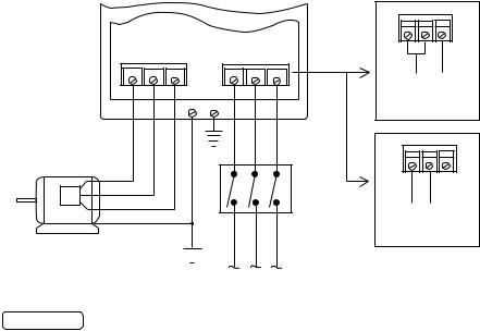
11.0 MICRO SERIES POWER WIRING DIAGRAM
L1 L2 N
T1 T2 T3 |
L1 L2 L3 |
120 Vac SINGLE GNDGND PHASE INPUT WIRING DIAGRAM
L1 L2 N
DISCONNECT |
240 Vac SINGLE |
PHASE INPUT |
|
MEANS |
WIRING DIAGRAM |
(REQUIRED) |
|
GND 
FUSED INPUT
VOLTAGE
 WARNING Do not connect incoming AC power to output terminals T1, T2, or T3.. Severe damage to the drive will result..
INSTALL, WIRE, AND GROUND IN ACCORDANCE WITH ALL APPLICABLE CODES..
NOTES:
1.Wire the motor for the proper voltage per the output rating of the drive.. Motor wires MUST be run in a separate steel conduit away from control wiring and incoming AC power wiring..
2.Do not install contactors between the drive and the motor without consulting LEESON for more information.. Failure to do so may result in drive damage..
3.Remove any existing, and do not install, power factor correction capacitors between the drive and the motor.. Failure to do so will result in drive damage..
4.Use only UL and CSA listed and approved wire..
5.Minimum wire voltage ratings: 300 V for 120, 200 and 240 VAC systems, and 600 V for 400, 480, and 590 VAC systems..
6.Wire gauge must be based on a minimum of 150% of the rated output current of the drive, and a minimum 75 C insulation rating.. Use copper wire only..
7.Wire and ground in accordance with NEC or CEC, and all applicable local codes..
26
 Loading...