


S P E E D M A S T E R®

 ®
®
174102, 174103 & 174107
NEMA 4X SCR MOTOR CONTROLS


 Manual Operation


LIMITED WARRANTY
A.Warranty - LEESON Electric warrants that its products will be free from defects in material and workmanship for a period of one (1) year from the date of shipment thereof. Within the warranty period, LEESON will repair or replace such products that are returned to LEESON or to the nearest Branch Office, with shipping charges prepaid. At our option, all return shipments are F.O.B. LEESON or its Branch Office. This warranty shall not apply to any product that has been subject to misuse, negligence, or accident; or misapplied; or repaired by unauthorized persons; or improperly installed. LEESON is not responsible for removal, installation, or any other incidental expenses incurred in shipping the product to or from the repair point.
B.Disclaimer - The provisions of Paragraph A are LEESON’s sole obligation and exclude all other warranties of MERCHANTABILITY or use, express or implied. LEESON further disclaims any responsibility whatsoever to the customer or any other persons for injury to person or damage or loss of property of value caused by any product that has been subject to misuse, negligence, or accident, or misapplied or modified by unauthorized persons or improperly installed.
C.Limitations of Liability - In the event of any claim or breach of any of LEESON’s obligations, whether expressed or implied, and particularly of any claim of a breach of warranty claimed in Paragraph A, or of any other warranties, express, or implied, or claim of liability that might, despite Paragraph B, be decided against us by any lawful authority, LEESON shall under no circumstances be liable for any consequential damages, losses, or expense arising in connection with the use of, or inability to use, LEESON’s product for any purpose whatsoever. An adjustment made to the warranty does not void the warranty, nor does it imply an extension of the original one (1) year warranty period. Product serviced and/or parts replaced by a no-charge basis during the warranty period carry the unexpired portion of the original warranty only.
If for any reason any of the forgoing provisions shall be ineffective, LEESON’s liability for damages arising out of its manufacture or sale if equipment, or use thereof, whether such liability is based on warranty, contract, negligence, strict liability in tort, or otherwise, shall not in any event exceed the full purchase of such equipment.
Any action against LEESON based upon any liability or obligation arising hereunder or under any law applicable to the sale of equipment or the use thereof must be commenced within one year after the cause of such action arises.

SPEEDMASTER™ OPERATION MANUAL |
i |
Safety Warnings
SHOCK |
AVOID |
KEE |
OID |
HAZARD |
HEAT |
DR |
ATION |
•This symbol denotes an important safety tip or warning. Please read these instructions carefully before performing any of the procedures contained in this manual.
•DO NOT INSTALL, REMOVE, OR REWIRE THIS EQUIPMENT WITH POWER APPLIED. Have a qualified electrical technician install, adjust and service this equipment. Follow the National Electrical Code and all other applicable electrical and safety codes, including the provisions of the Occupational Safety and Health Act (OSHA), when installing equipment.
•Reduce the chance of an electrical fire, shock, or explosion by proper grounding, over-current protection, thermal protection, and enclosure. Follow sound maintenance procedures.
Warning
It is possible for a drive to run at full speed as a result of a component failure. LEESON strongly recommends the installation of a master switch in the main power input to stop the drive in an emergency.
Circuit potentials are at 115 VAC or 230 VAC above earth ground. Avoid direct contact with the printed circuit board or with circuit elements to prevent the risk of serious injury or fatality. Use a non-metallic screwdriver for adjusting the calibration trimpots. Use insulated tools if working on this drive with power applied.
ii |
SPEEDMASTER™ OPERATION MANUAL |
Contents |
|
Warranty Statement |
Inside Front Cover |
Safety Warnings |
i |
Specifications |
1 |
Dimensions |
2 |
Overview |
3 |
Installation |
4 |
Mounting . . . . . . . . . . . . . . . . . . . . . . . . . . . . . . . . . . . . . . . . . . . . . . . .4 Removing the Plastic Cover . . . . . . . . . . . . . . . . . . . . . . . . . . . . . . . . . .4 Line fusing . . . . . . . . . . . . . . . . . . . . . . . . . . . . . . . . . . . . . . . . . . . . . . .4 Connections . . . . . . . . . . . . . . . . . . . . . . . . . . . . . . . . . . . . . . . . . . . . . .5 Field Output . . . . . . . . . . . . . . . . . . . . . . . . . . . . . . . . . . . . . . . . . . . . . .9 Voltage Switches . . . . . . . . . . . . . . . . . . . . . . . . . . . . . . . . . . . . . . . . . .9
Calibration |
10 |
Calibration procedure . . . . . . . . . . . . . . . . . . . . . . . . . . . . . . . . . . . . . . . |
.12 |
MINIMUM SPEED (MIN SPD) . . . . . . . . . . . . . . . . . . . . . . . . . . . . . . |
12 |
MAXIMUM SPEED (MAX SPD) . . . . . . . . . . . . . . . . . . . . . . . . . . . . . . |
13 |
REGULATION (IR COMP) . . . . . . . . . . . . . . . . . . . . . . . . . . . . . . . . . |
13 |
TORQUE LIMIT (TORQUE) . . . . . . . . . . . . . . . . . . . . . . . . . . . . . . . . . |
14 |
ACCELERATION (ACCEL) . . . . . . . . . . . . . . . . . . . . . . . . . . . . . . . . . |
15 |
DECELERATION (DECEL) . . . . . . . . . . . . . . . . . . . . . . . . . . . . . . . . . |
15 |
Calibration procedure conclusion . . . . . . . . . . . . . . . . . . . . . . . . . . . . |
15 |
Operation |
17 |
Before applying power . . . . . . . . . . . . . . . . . . . . . . . . . . . . . . . . . . . . . . |
.17 |
Startup . . . . . . . . . . . . . . . . . . . . . . . . . . . . . . . . . . . . . . . . . . . . . . . . . . . |
.18 |
174102 . . . . . . . . . . . . . . . . . . . . . . . . . . . . . . . . . . . . . . . . . . . . . . . . . |
18 |
SPEEDMASTER™ OPERATION MANUAL |
Contents |
iii |
174103 . . . . . . . . . . . . . . . . . . . . . . . . . . . . . . . . . . . . . . . . . . . . . . . . |
.19 |
174107 . . . . . . . . . . . . . . . . . . . . . . . . . . . . . . . . . . . . . . . . . . . . . . . . . |
20 |
Application Notes |
21 |
Inhibit circuit . . . . . . . . . . . . . . . . . . . . . . . . . . . . . . . . . . . . . . . . . . . . . . . |
21 |
Decelerating to minimum speed . . . . . . . . . . . . . . . . . . . . . . . . . . . . . . . . |
23 |
Dynamic Braking . . . . . . . . . . . . . . . . . . . . . . . . . . . . . . . . . . . . . . . . . . . . |
24 |
Multiple Fixed Speeds . . . . . . . . . . . . . . . . . . . . . . . . . . . . . . . . . . . . . . . |
26 |
Adjustable speeds using potentiometers in series . . . . . . . . . . . . . . . . . . |
27 |
Independent adjustable speeds . . . . . . . . . . . . . . . . . . . . . . . . . . . . . . . . |
28 |
RUN/JOG switch . . . . . . . . . . . . . . . . . . . . . . . . . . . . . . . . . . . . . . . . . . . |
29 |
RUN/JOG option #1 . . . . . . . . . . . . . . . . . . . . . . . . . . . . . . . . . . . . . . . |
29 |
RUN/JOG option #2 . . . . . . . . . . . . . . . . . . . . . . . . . . . . . . . . . . . . . . . |
30 |
Leader-follower application . . . . . . . . . . . . . . . . . . . . . . . . . . . . . . . . . . . . |
31 |
Single speed potentiometer control of multiple drives . . . . . . . . . . . . . . . |
32 |
Reversing . . . . . . . . . . . . . . . . . . . . . . . . . . . . . . . . . . . . . . . . . . . . . . . . . |
33 |
Troubleshooting |
34 |
Before troubleshooting . . . . . . . . . . . . . . . . . . . . . . . . . . . . . . . . . . . . . . .34 Power and Current Limit LEDs . . . . . . . . . . . . . . . . . . . . . . . . . . . . . . . . .35 Troubleshooting Tables . . . . . . . . . . . . . . . . . . . . . . . . . . . . . . . . . . . . . . .36 Replacement Parts . . . . . . . . . . . . . . . . . . . . . . . . . . . . . . . . . . . . . . . . . .39

iv |
|
SPEEDMASTER™ OPERATION MANUAL |
|
Illustrations |
|
||
Figure 1. |
|
174102, 174103 & 174107 Dimensional Diagrams . . . . . . . . . . . |
. .2 |
Figure 2. |
|
Cover removal for terminal strip access . . . . . . . . . . . . . . . . . . . |
. .6 |
Figure 3. |
|
Drive connections . . . . . . . . . . . . . . . . . . . . . . . . . . . . . . . . . . . . |
. .7 |
Figure 3a. |
External Signal Connections, 174103.00 . . . . . . . . . . . . . . . . . . |
.8 |
|
Figure 4. |
|
Voltage Switches . . . . . . . . . . . . . . . . . . . . . . . . . . . . . . . . . . . . . . |
.9 |
Figure 5. |
|
Calibration Trimpot Layout . . . . . . . . . . . . . . . . . . . . . . . . . . . . . . . |
11 |
Figure 6. Recommended TORQUE and IR COMP Settings . . . . . . . . . . . . |
16 |
||
Figure 7. |
|
Inhibit Plug with Run/Coast to Minimum Speed . . . . . . . . . . . . . . |
22 |
Figure 8. |
|
Run/Decelerate to Minimum Speed Switch . . . . . . . . . . . . . . . . . . |
23 |
Figure 9. |
|
Dynamic Brake Connection . . . . . . . . . . . . . . . . . . . . . . . . . . . . . . |
25 |
Figure 10. |
Multiple Fixed Speeds . . . . . . . . . . . . . . . . . . . . . . . . . . . . . . . . . |
26 |
|
Figure 11. |
Adjustable Fixed Speeds Using Potentiometers in Series . . . . . . |
27 |
|
Figure 12. |
Independent Adjustable Speeds . . . . . . . . . . . . . . . . . . . . . . . . . |
28 |
|
Figure 13. |
RUN/JOG Switch Option #1 . . . . . . . . . . . . . . . . . . . . . . . . . . . . |
29 |
|
Figure 14. RUN/JOG Switch Option #2 Connection to |
|
||
|
|
Speed Adjust Potentiometer . . . . . . . . . . . . . . . . . . . . . . . . . . . . |
30 |
Figure 15. |
Leader-Follower Application . . . . . . . . . . . . . . . . . . . . . . . . . . . . |
31 |
|
Figure 16. |
Single Speed Potentiometer Control of Multiple Drives . . . . . . . |
32 |
|
Figure 17. |
Reversing Circuit Connection . . . . . . . . . . . . . . . . . . . . . . . . . . . |
33 |
|
Figure 18. |
Current Limit LED . . . . . . . . . . . . . . . . . . . . . . . . . . . . . . . . . . . . |
35 |
|
Tables |
|
||
Table 1. |
Recommended Line Fuse Sizes . . . . . . . . . . . . . . . . . . . . . . . . . . |
.5 |
|
Table 2. |
Field Output Connections . . . . . . . . . . . . . . . . . . . . . . . . . . . . . . . . |
.9 |
|
Table 3. |
Replacement Parts . . . . . . . . . . . . . . . . . . . . . . . . . . . . . . . . . . . . . |
39 |
|

SPEEDMASTER™ OPERATION MANUAL |
1 |
Specifications
|
Max. |
|
|
|
|
Armature |
HP Range |
HP Range |
|
|
Current |
with 115 VAC |
with 230 VAC |
|
Model |
(Amps DC) |
Applied |
Applied |
Style |
174102 |
10.0 |
1/8–1 |
1/4–2 |
NEMA 4X |
174103 |
10.0 |
1/8–1 |
1/4–2 |
NEMA 4X |
174107 |
10.0 |
1/8–1 |
1/4–2 |
NEMA 4X |
|
|
|
||
AC Line Voltage |
|
115 VAC or 230 VAC ±10%, 50/60 Hz, single phase |
||
Armature Voltage (115 VAC Input) |
|
|
0–90 VDC |
|
Armature Voltage (230 VAC Input) |
|
|
0–180 VDC |
|
Form Factor |
|
|
1.37 at base speed |
|
Field Voltage (115 VAC Input) |
50 VDC (F1 to L1); 100 VDC (F1 to F2) |
|||
Field Voltage (230 VAC Input) |
100 VDC (F1 to L1); 200 VDC (F1 to F2) |
|||
Max. Field Current |
|
|
|
1 ADC |
Accel. Time Range: |
|
|
|
|
for 0–90 VDC Armature Voltage |
|
|
1 – 15 seconds |
|
for 0–180 VDC Armature Voltage |
|
|
1 – 15 seconds |
|
**Analog Input Voltage Range (signal must be isolated; S1 to S2): |
|
|||
for 0–90 VDC Armature Voltage |
|
|
0 – 1.4 VDC |
|
for 0–180 VDC Armature Voltage |
|
|
0 – 2.8 VDC |
|
Decel. Time Range: |
|
|
|
|
for 0-90 VDC Armature Voltage |
|
|
1 – 15 seconds |
|
for 0–180 VDC Armature Voltage |
|
|
1 – 15 seconds |
|
Current Limit Range: |
|
|
|
|
for 0–90 VDC Armature Voltage |
|
|
0 – 14 A |
|
for 0–180 VDC Armature Voltage |
|
|
0 – 13.5 A |
|
Input Impedance (S1 to S2) |
|
|
3M ohms |
|
Load Regulation |
|
|
1% base speed or better |
|
Vibration |
|
|
1G max (0–50 Hz) |
|
Ambient Temp. Range (cased drive) |
|
|
10°C–40°C |
|
**Does not Apply to 174103 |
|
|
|
|
2 |
SPEEDMASTER™ OPERATION MANUAL |
||
Dimensions |
|
|
|
|
5.63 [143] |
|
|
|
5.16 [ 131] |
|
|
|
|
POWER |
0.19 [5.00] |
|
|
|
|
|
|
ON |
SLOTTED HOLES |
|
|
|
4 PLACES |
|
S P E E D M A S T E R® |
OFF |
|
5
4 3 2
1  0
0
6 7
8
9
1 0 
7.50 [191] |
5.50 [140] |
SPEED |
|
®
ADJUSTABLE SPEED
DC MOTOR CONTROL
0.73 [18.5] |
BOTTOM PLATE |
|
|
CONDUIT HOLES |
|
2 PLACES |
|
4.56 [116]
2.12 [53.8]
2.20
[55.9]
3.40
[86.4]
ALL DIMENSIONS IN INCHES [MILLIMETERS]
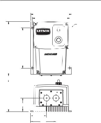
Figure 1. 174102, 174103 & 174107 Dimensional Diagrams
SPEEDMASTER™ OPERATION MANUAL |
3 |
Overview
The following is a quick-step guide to setting up the control. For more detailed installation information, read the Installation (page 4) and Calibration (page 10) sections of this user’s manual.
1.Mount the control using the 4 slotted holes on the heat sink. The slotted holes are 0.19 inches [5 mm] (see Figure 1).
2.Remove the plastic cover by unscrewing the 6 screws on the front cover and 5 screws on the bottom plate. NOTE: Do not remove the 3 screws securing the bottom plate to the heatsink.
3.Change the line fuse if necessary. If the horsepower rating of the motor being used is less than the maximum HP rating of the drive, the line fuse may have to be replace with a lower rated one.
3.Wire the control through the conduit holes, or optional aluminum hardware. NOTE: Do not connect the control while power is applied.
4.Assure that settings on voltage switches are correct (SW501 & SW502).
5.Apply power to the drive.
5.Calibrate the trimmer pots, if neccessary.
6.Re-install the plastic cover.
4 |
SPEEDMASTER™ OPERATION MANUAL |
Installation
Mounting
174102, 174103 and 174107 drives may be vertically wall mounted using the four 0.19 inch (5 mm) slotted holes on the attached heat sink (see Figure 1, Page 2). For motor loads less than 5 ADC, the drive may be bench mounted horizontally, or operated without mounting.
Removing the Plastic Cover
Connections, calibration, and other settings must be made internally. After mounting, use the following procedure to remove the plastic cover and configure the control:
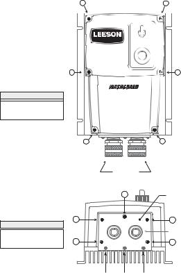
1.Remove the six (6) phillips screws on the front cover. NOTE: The two shorter screws (#6 - 32 x 2 ½) are for the two lower holes on the front of the cover (see Figure 2, page 6).
2.Remove the five (5) phillips screws on the bottom plate (see
Figure 2, page 6). NOTE: DO NOT remove the 3 screws securing the bottom plate to the heatsink.
Line fusing
Line fuses are preinstalled on all 174102, 174103 and 174107 drives. If the horsepower rating of the motor being used is less than the maximum horsepower rating of the drive, the line fuse may have to be replaced with a lower rated one. Refer to Table 1 for recommended line fuse sizes.
|
SPEEDMASTER™ OPERATION MANUAL |
Installation |
5 |
|
|
|
Table 1. Recommended Line Fuse Sizes |
|
|
||
|
|
FUSE SIZE (AMPS) |
FUSE SIZE (AMPS) |
|
|
|
MOTOR HP |
@ 115 VAC INPUT |
@ 230 VAC INPUT |
|
|
1/4 |
5 |
3 |
|
|
|
1/3 |
8 |
3 |
|
|
|
1/2 |
8 |
5 |
|
|
|
3/4 |
10 |
8 |
|
|
|
1 |
15 |
8 |
|
|
|
1 1/2 |
– |
10 |
|
|
|
|
2 |
– |
15 |
|
|
Connections
Warning
Do not connect this equipment with power applied.
Failure to heed this directive may result in fire or serious injury.
1.Install conduit hardware through the two 0.73” (18.5 mm) conduit holes or by using aluminum cord connectors attached to the line seal plate on the bottom of the case.
2.Connect external wiring to the terminal block as shown in
Figure 3, page 7.
6 |
Installation |
SPEEDMASTER™ OPERATION MANUAL |
12
S T E P # 1
REMOVE THE SIX (6) PHILLIPS SCREWS ON THE FRONT CASE.
NOTE: THE TWO SHORTER SCREWS (#6 - 32 x 2 ½) ON THE FRONT CASE ARE USED AT HOLE LOCATIONS 5 & 6.
|
POWER |
|
|
|
|
|
ON |
|
|
|
|
|
|
|
S P E E D M A S T E R® |
|
OFF |
|
|
4 |
5 |
6 |
|
|
|
7 |
|
||
3 |
|
|
8 |
|
2 |
|
|
9 |
|
|
|
|
|
|
1 |
|
|
1 |
|
|
0 |
0 |
|
|
|
|
|
|
|
3 |
SPEED |
|
4 |
|
®
ADJUSTABLE SPEED
DC MOTOR CONTROL
56
CUSTOMER
SUPPLIED
WATERTIGHT CORD
CONNECTORS (2)
|
|
1 |
BOTTOM PLATE |
|
|
|
|
|
2 |
|
3 |
S T E P # 2 |
|
|
CUSTOMER SUPPLIED |
|
|
|
|
REMOVE THE FIVE (5) |
|
|
WATERTIGHT CORD |
|
|
CONNECTORS (2) |
|
PHILLIPS SCREWS ON |
|
|
|
4 |
|
5 |
|
THE BOTTOM PLATE. |
|
||
|
|
|
D O N O T R E M O V E
THE THREE (3) SCREWS SECURING
THE BOTTOM PLATE TO THE HEATSINK
Figure 2. Cover removal for terminal strip access

SPEEDMASTER™ OPERATION MANUAL |
Installation |
7 |
MOV501
MOV503
MO
F502
L2 FRM SW L1 |
A2 TO SW A1 |
L2 TO SW L1 |
A2 FRM SW A1 |
F501
TB501
F1 |
F2 |
L2-115 |
L2-230 |
L1 |
A2 |
A1 |
|
|
|
+ |
|
|
230 VAC |
|
|
|
|
|
|
|
115 VAC |
|
EARTH GROUND |
FIELD |
LINE VOLTAGE INPUT |
MOTOR |
(GREEN SCREW) |
OUTPUT |
(115 or 230 VAC) |
ARMATURE |
FIELD OUTPUT CONNECTIONS
The field output is for shunt wound motors only. Do not make any connections to F1 and F2 when using a permanent magnet motor.
For field motor connections, see Table 2 on Page 9.
Figure 3. Drive connections
8 |
Installation |
SPEEDMASTER™ OPERATION MANUAL |
3
2
1
SO501
PL501
TQ LIMIT
C3
IR COMP
|
|
IC1 |
|
|
|
R9 |
|
|
|
|
R7 |
|
CARD |
|
|
R8 |
C4 |
||
SIG MIN. |
SIG MAX |
|||
|
||||
P502 |
|
P501 |
|
|
ACCEL |
|
DECEL |
PCM |
|
|
|
|||
D501 |
|
|
|
|
D502 |
|
|
|
|
MIN. SPD |
|
MAX SPD |
|
|
R6 |
R5 |
|
|
|
|
|
1 |
2 |
3 |
|
4 |
|
|
|
|
|
||||
|
|
|
|
|
|
TB501 |
|
|
|
Q2 |
|
R1 |
T501 |
|
|
|
|
|
C1 |
|
RSH |
|
|
|
|
R3 |
|
|
|
|
Q1 |
|
|
|
|
|
|
C2 |
R4 |
|
|
|
|
|
|
|||
|
|
|
|
|
||
|
|
|
|
|
|
|
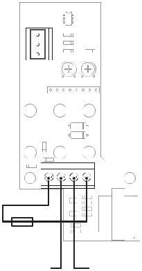
RSH = 1000 OHM for 4 - 20 mA
RSH = 250 OHM for 10 - 50 mA R2
RSH = NOT USED for 1 - 5 mA
RSH = NOT USED for 0 - 10V signal
TERMINAL 2 |
TERMINAL 3 |
+ 0 - 10V |
(-) COMMON |
SPEED ADJUST |
|
SIGNAL INPUT |
|
Figure 3a. External Signal Connections
For 174103.00 Only
SPEEDMASTER™ OPERATION MANUAL |
Installation |
9 |
Field Output
The field output is for shunt wound motors only. Do not make any connections to F1 and F2 when using a permanent magnet motor. Use 18 AWG wire to connect the field output to a shunt wound motor. Table 2 lists the field output connections.
Table 2. Field Output Connections
Line Voltage |
Approx. Field |
Connect Motor |
(VAC) |
Voltage (VDC) |
Field To |
115 |
50 |
F1 and L1 |
115 |
100 |
F1 and F2 |
230 |
100 |
F1 and L1 |
230 |
200 |
F1 and F2 |
Voltage Switches
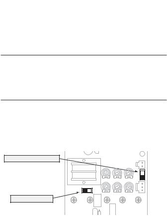
•Set voltage switch SW501 to either 115 or 230 to match the AC line voltage (see Figure 4 below).
•Set voltage switch SW502 to either 90 or 180 to match the
maximum armature voltage (see Figure 4 below).
C501 |
IC502 |
|
|
|
MAX ARMATURE VOLTAGE SWITCH |
|
|
|
|
SW502 (90 or 180 VDC) |
|
|
SO501 |
|
|
TQ LIMIT |
ACCEL |
DECEL |
|
T501 |
|
|
|
|
SW501 |
|
|
|
SO502 |
|
R501 |
|
|
|
230 - 115 |
IR COMP |
MIN SPD |
MAX SPD |
|
AC LINE VOLTAGE SWITCH
SW501 (115 or 230 VAC)
S3 S2 S1 180 - 90 SW502 INHIBIT C504
OV502 |
R502 |
C503 |
Figure 4. Voltage Switches
 Loading...