

Page 1
SLIM LED POLO
IP54 Round Bulkhead
LTP3CCTEM
These instructions should be read carefully and retained after installation for further
reference and maintenance.
SAFETY
l Before installation, ensure that the mains supply to the luminaire is switched off and the
circuit supply fuses are removed or circuit breaker turned off
l It is recommended that a qualified electrician is consulted or used for the installation of
this luminaire and installed to the current edition of the IEE wiring regulations
l Check that the total load on the circuit, including this luminaire, does not exceed the rating
of the circuit cable, fuse or circuit breaker
RATINGS
l This luminaire is of Class II construction and it does not require an earth connection
l IP54 rated
l F marked, suitable for installation on normal flammable surfaces
l Working situation: -20 C to 40 C
l 220-240V AC rated
l CE Approved
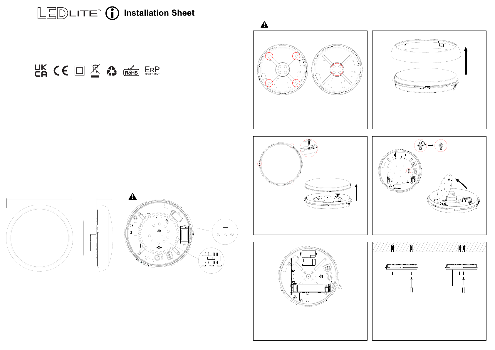
DIMENSIONS: CCT & POWER ADJUSTABLE:
Ø315mm
0 0
80mm
Switch off the mains supply before changing power or CCT
CCT Changeable / Tri Wattage
9W/14W/18W
c/w Emergency pack
220-240V
INSTALLATION INSTRUCTIONS:
Switch off the mains supply before installation.
A B
1. Chose a suitable flat installation position.
1
2. Remove the clip-on trim ring from the slim
polo body.
1
170mm
TECHNICAL SPECIFICATIONS:
l Input Voltage: 220-240V/AC
Tri-Power Selectable: 9W / 14W / 18Wl
Light Output: 9W - 900lml
14W - 1450lm
18W - 1850lm
CCT Changeable (switch): l
3000K/4000K/6500K
CRI > 80l
IP Rating: IP54l
35.5mm
Use the driver switch
to change the power
3. Remove the diffuser screws and separate
it from the base.
Use the LED gear tray switch
to change the CCT temperature
2
4. Turn the butterfly button to open the hinged
gear tray to allow access to the connections.
2
Protection Class: Class IIl
Housing: PC Body & Diffuserl
Battery Type: LiFePO4 6.4V 1000mAhl
Charge Time ≥ 24hl
Duration > 180minl
Operating Temp.: -15 C to +40 Cl
0 0
Dimensions: Diameter 315mm / depth 80mml
Warranty: 5 years (3 years for battery) l
5. Enter supply cable into the luminaire ensuring
that the hole is smooth or a grommet is fitted
and connect it to the terminal block (see
wiring instructions).
6. Position and fix the base to a suitable solid
surface using suitable fixings and close the
hinged LED gear tray
Page 2
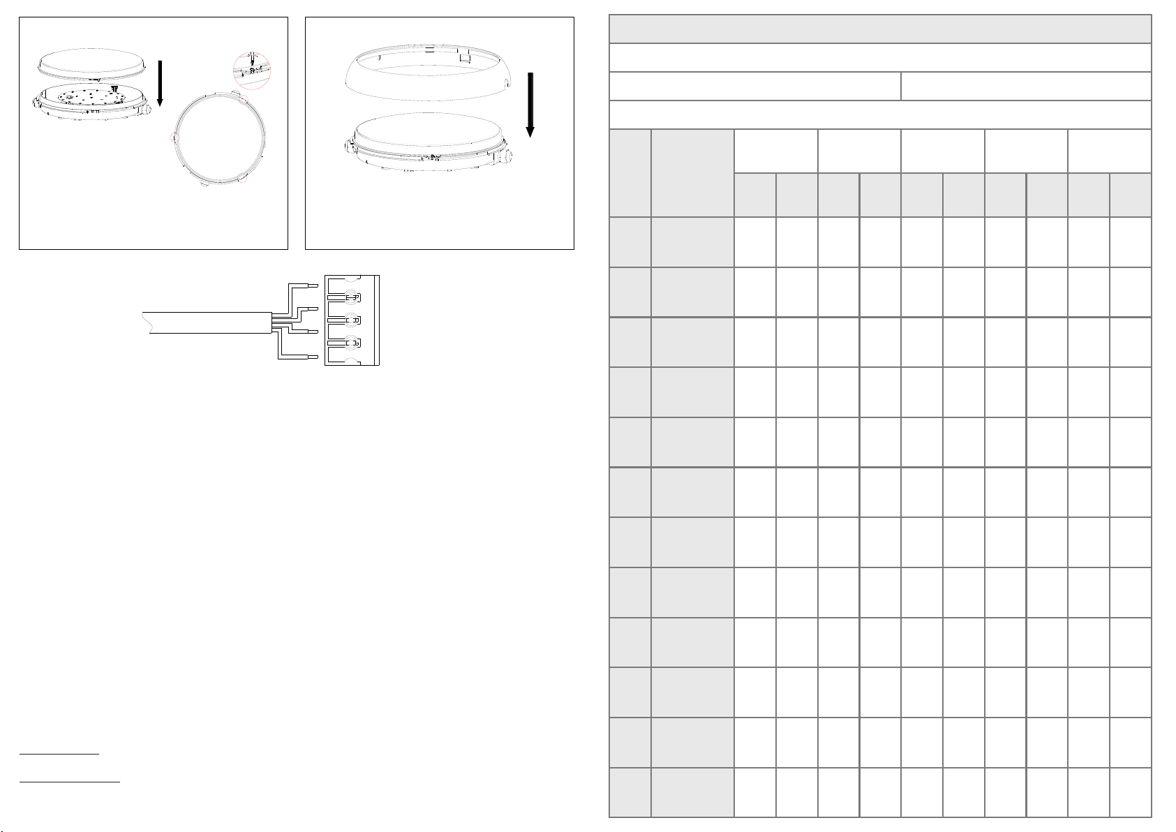
INSTALLATION, MAINTENANCE AND OPERATION CHECK RECORD
Location:
1
2
7. Re-fit the diffuser by placing it over the base
8. Install the clip-on trim ring on the body.
and lock into position using the screws.
WIRING DIAGRAM:
Mains Supply
Blue
Black
Brown
Yellow
Green
N
E
SL
PL
l Terminate the cable into the terminal block mounted on the underside of the gear tray ensuring
correct polarity is observed and any bare conductors are sleeved.
l In addition, a secondary permanent live supply should be fed to the luminaire, in line with the
switch mains supply.
l The permanent supply MUST be taken from the same phase as the switch live supply
and MUST be wired so that upon test, it is isolated at the same time as the switch supply.
l Connect the battery supply to the module by joining the connectors, ensuring correct polarity
is observed.
l The green LED fitted to the luminaire should be ON after reconnecting the power supply, indicating
that the batteries are charging.
l The batteries should be charged for at least 24 hours before carrying out a full discharge test to
check if the maintained duration is being achieved.
OPERATION / MAINTENANCE
1. Nominal battery life is 4 years, after which time they should be replaced with a suitable equivalent.
2. When the lamp operates from the battery supply it will be at a reduced light level.
3. Keep the luminaire clean so it will not affect performance.
OPERATIONS CHECK
Periodic testing should be carried out monthly by simulating a failure of supply, causing the fitting
to be energised from its battery. Interruption of the supply should be carried out by the operation
of a local key switch or other isolation device. During this period all fittings should be examined
visually to ensure that they are functioning correctly. At the end of the test period the supply should
be restored and all indicator lamps or devices checked to ensure that the normal supply has been
restored.
The duration of the simulated failure should be:
Each month: Isolate the power supply and check the light is illuminated. This test should last for
no more than 45 minutes. Complete the test record form supplied.
Once each year: Isolate the power supply and check that the light is still illuminated after 3 hours.
Complete the test record form.
For further information visit www.tlc-direct.co.uk
Installation Date:
Installed By:
Month Test
1
2
3
4
5
6
7
8
9
10
11
Short
Short
Short
Short
Short
Short
Short
Short
Short
Short
Short
12
3 hr Endurance
Installation Test Duration:
Year: Year: Year: Year: Year:
Sign
Date
Sign
Date
Sign
Date
Sign
Date
Sign
Date
 Loading...