

Page 1
User Instructions
10W Smart WiFi & Bluetooth
LTTFDP
CCT Changeable
LED Fire Rated Downlight c/w Plaster Bezel*
General Instructions
These instructions should be read carefully and retained after installation for further
reference and maintenance.
Important information
It is recommended that luminaires are installed by a qualified electrician ensuring the
installation complies with current IEE wiring regulations & local building control.
• Before installation or maintenance ensure that the mains supply to the luminaire
is switched off and the circuit supply fuses are removed or circuit breaker turned off.
• Check that the total load on the circuit, including when this luminaire is fitted, does
not exceed the rating of the circuit cable, fuse or circuit breaker.
• We will not accept responsibility for any claims arising from a poor installation.
• Suitable for bathroom and shower room use.
Dimensions:
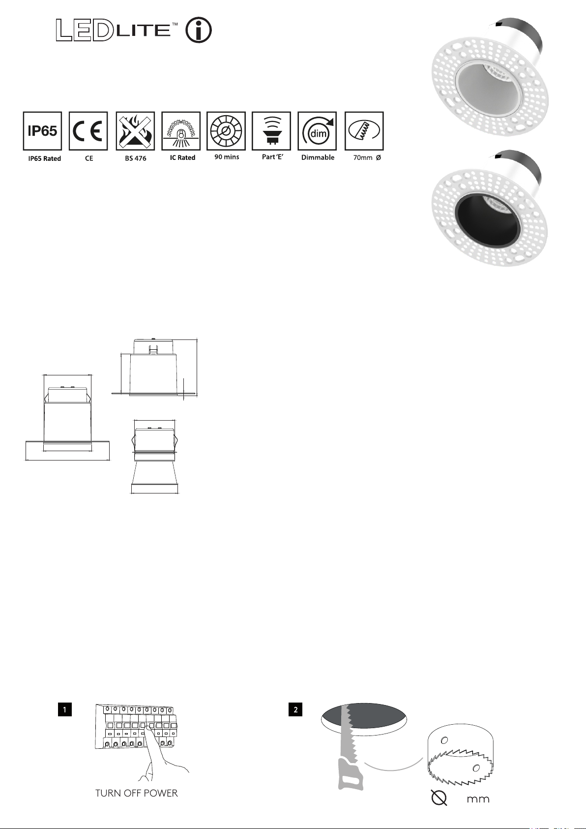
66.5mm
55mm
3.9mm
Ø56.8mm
Ø68mm
Ø118mm
Ø66mm
Specifications:
• LED Voltage Range: 33-39V/DC
• LED Current: 230mA
79.6mm
• Wattage: 10W
• Beam Angle: 40
• CCT Changeable (3000K/4000K/6000K)
• White & Black Reflector Included
• Lumens: White Reflector Black Reflector
3000K 800lm 600lm
4000K 870lm 660lm
6000K 840lm 640lm
0
LTTFDDR or LTTFWDR drivers
*for use with
(not included)
• Solid Joist & I-Joist Fire Rated
• Insulation Coverable
• Plaster Bezel & Cover Included
• Cut-out: 70mm
• Housing Materials: Aluminium + Iron
• Warranty: 5 Years
• IP65 Rated
Installation:
• Turn the power off before commencing installation (see Fig.1).
• Cut a suitable hole in the ceiling as as per the cut-out details ensuring that it does not infringe with electrical cables,
water/gas pipes or ceiling joists. (see Fig.2).
• The downlight is IC Rated and designed for use with insulated material, it does not need extra IC cage accessories.
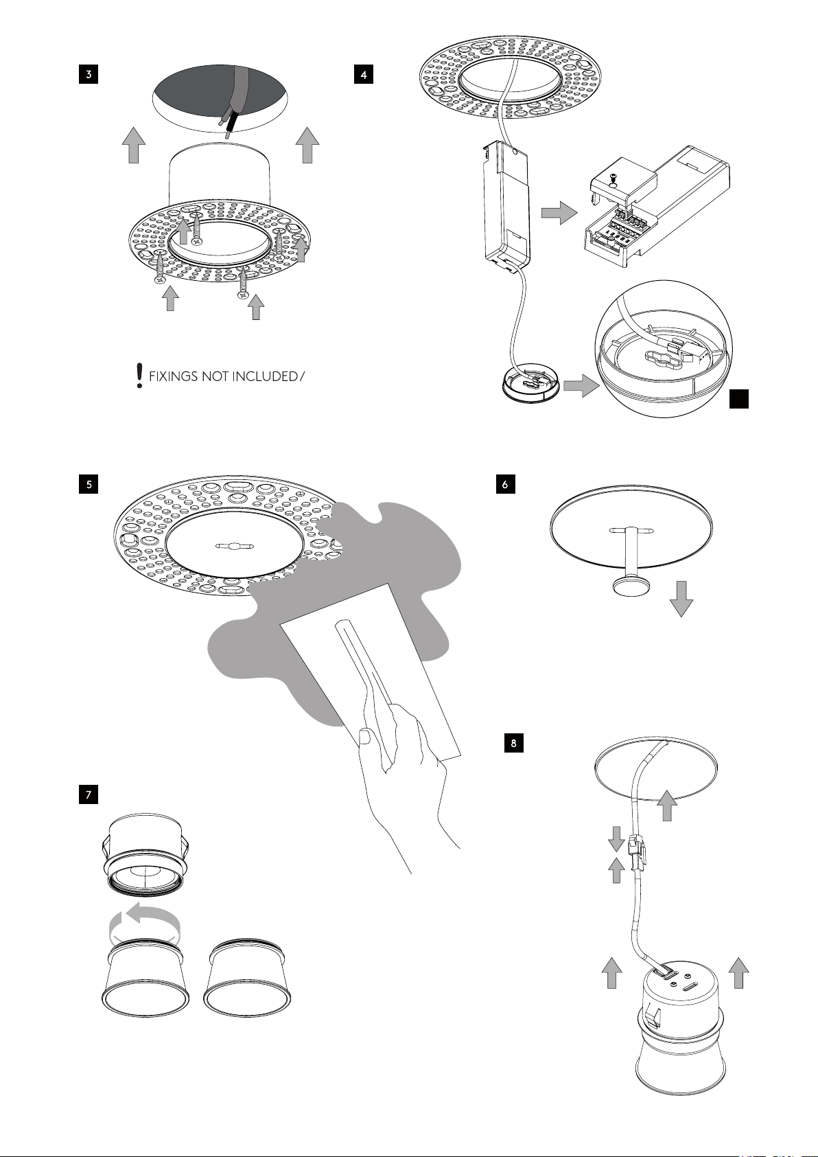
• Fix the trim-less bracket into the ceiling by screws.(see Fig.3).
• Connect the driver to the downlight (see Fig.4).
• Fix the DC cable from the driver to the plastic pad of the painting cover.(see Fig.4.1).
• Mount the plastic housing cover before skimming, to avoid plaster getting inside.(see Fig.5).
• Before the plaster is dry, remove the plastic cover protection using the plastic key provided.(see Fig.6).
• Install the required reflector - white and black reflectors included.(see Fig.7).
• Connect the DC cable from the driver to the DC cable from the LED module and make sure they are fully connected.
Insert the LED module into the trim-less bracket.(see Fig.8).
• Test for correct operation.
• If you need to remove the downlight use a rubber suction cup & pull down (suction cup not included).
70
Page 2
4.1
White
Black
 Loading...