

Page 1
User Instructions
LTLPS9/LTLPW9 - 9W LED LoPro9 Light
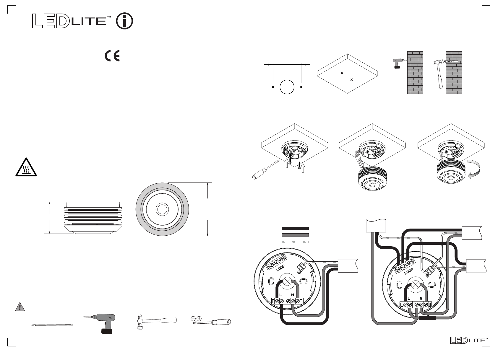
Step 1: Identify the location and direction of any hidden supply cables or service
pipes before drilling fixing holes.
Step 2: Mark the position of the fixing holes onto the wall/ceiling surface adjacent to
the supply wiring (Fig.1).
Step 3: Drill holes at the positions marked and fit the plastic wall plugs (Fig.2).
IP44
220-240V
Please read these instructions before commencing installation &
retain them for future reference.
Important information
It is recommended that the fittings are installed by a qualified electrician ensuring
the installation complies with current IEE wiring regulations & local building control.
• These products are designed for connection to a 220-240V mains supply.
• We cannot accept responsibility for any claims arising from a poor installation.
Important User Advice
• Always switch off mains supply before installation.
• This Iuminaire is suitable for indoor use only and should not be fitted to damp
or wet surfaces such as freshly plastered or painted walls.
CAUTION! Hot Surface. Do Not Touch.
The surface of the LoPro9 becomes hot when the light is on. Please
allow time to cool down completely before handling.
Dimensions:
Ø90mm
50mm
Specifications:
• Voltage Range: 220-240VAC
• Nom. Watts: 9W
• Light Output: 765± Lumens
• LED Colour: 3000/4000/6000K
• Power Factor > 0.90
• CRI > 80
Installation:
• Beam Angle: 120
• Dimmable with selected dimmers
• Body Colour: Polished White / Silver
• Material: Aluminium Alloy Body &
PC Lens
• IP Rating: IP44
0
48±2mm
(Fig.1)
Step 4: Screw the plastic base of the light fitting onto the wall/ceiling (Fig.3). Connect
the lamp wires to the base using the plugs (Fig. 4) and the mains wires as in the wiring
diagram below and tighten the terminal screws securely.
Connect lamp
to base
(Fig.3)
Step 5: Mount the light body onto the plastic base by screwing it clockwise until it
snaps into place (Fig.5). Inspect the unit to ensure secured installation. Switch the
mains power on to test for correct operation.
Wiring Diagram:
Live
Neutral
Earth
Brown
Blue
Green/Yellow
Green/Yellow
(Fig.4) (Fig.5)
LOOP
IN
BLUE
Green/Yellow
BROWN
SWITCH
(Fig.2)
LOOP
OUT
SWITCH
Warning!
Tools required:
12-04-2017
Switch off the power source before installation & maintenance
Pencil Electric drill Hammer Screwdriver
BLUE
BROWN
Standard Circuit
For further information visit www.tlc-direct.co.uk
BROWN Sleeve
Looping Circuit
 Loading...