

Page 1
LTHBEM3
HIGH VOLTAGE OUTPUT
170 V/DC
SELF TEST
Emergency Kit
for use with
LTHB200CCT High Bay
IP65
CONSTANT POWER
EMERGENCY OUTPUT
User Instructions
Please read these instructions and retain them for future reference.
Important information:
It is recommended that the emergency kit is installed by a qualified electrician
ensuring the installation complies with current IEE wiring regulations & local
building control.
• This product is designed for connection to a 220/240V/AC mains supply
• We cannot accept responsibility for any claims arising from a poor installation
• Always switch off mains supply before installation
• The fitting is Class I and does require an earth connection
• The LTHBEM3 has no internal adjustments or serviceable parts and therefore
the main cover should never be removed
• For installation in combination with LTHB200CCT High Bay, the wiring instructions
in this manual must be followed or the LTHBEM3 emergency kit may not function
as expected
• The Status LED/Test Button should be positioned in such a way as to be easily
visible under all circumstances to ensure quick and convenient functionality check
• Do not mount near gas or electric heaters
• Install the emergency kit in locations and at heights where it is not subject to
tampering by unauthorized personnel
• Repairs and maintenance must be carried out by qualified personnel
Emergency Testing and Battery Maintenance:
• Initial battery charge must be for a minimum of 24 hours before testing
• To achieve best performance the LTHBEM3 should be tested fully by
switching into emergency mode regularly in accordance with local testing
regulations. Any warranty claim must be accompanied by documentation
which records the dates of this maintenance procedure and signed by
maintenance personnel
• When first connecting the AC power check that the Green LED indicator is
flashing to confirm the battery is being charged. Once the battery is fully charged
the Green LED with be lit and stable
• Once fully charged turn the power off to simulate mains supply failure. The Red
LED should be on & the high bay will be in emergency mode.
Features:
• Easy wiring: directly connect to 220-240V/AC input of the LTHB200CCT
UFO LED High Bay
• Constant power output: 20W
• Universal input voltage range: 220-240V/AC, 50/60Hz
• IP Rating: IP65
• Suitable for 0/1-10V dimmable UFO LED High Bay ≤ 200W
• Battery protections: over temperature protection, over charge protection,
over discharge protection, short circuit protection
• Self-testing monthly / yearly
• UKCA, CE, RoHS approved
• 3 Years warranty
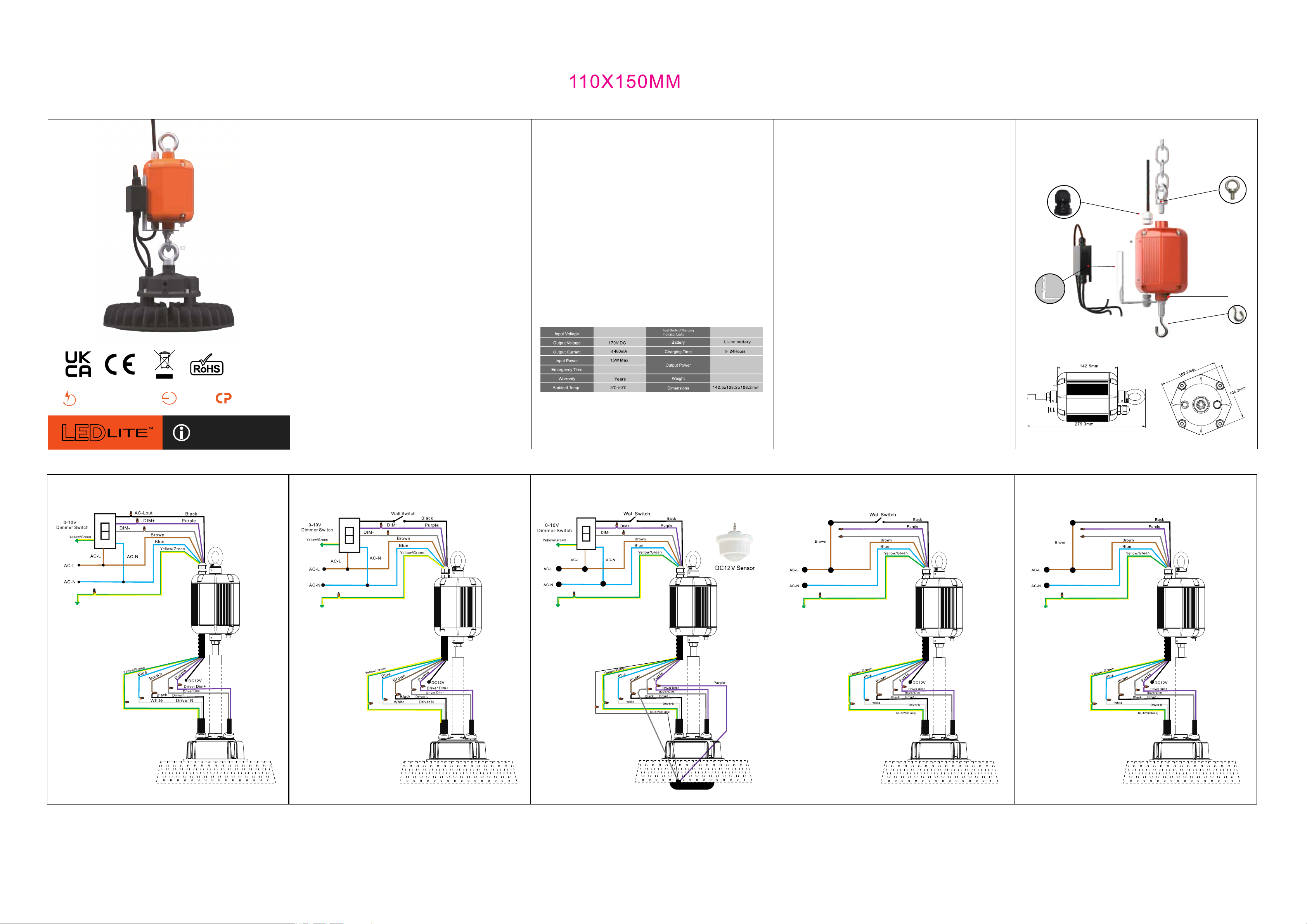
Specifications:
220-240V/AC, 50/60Hz
180 Minutes
3
Note: The LTHBEM3 Emergency kit is only for use with LTHB200CCT 200W
1-10V Dimmable & CCT Changeable UFO High Bay
Self-test with test Button
20W
2.2kg
Self-Test Function:
• Monthly inspection: The system simulates a power outage every 30 days for
30 seconds. It will quit and return to the mains power state automatically if
there is no fault.
• Annual inspection: The system simulates a power outage every 360 days
for 3 hours or until the battery power runs out. It will quit and return to the
mains power state automatically if there is no fault.
Test Button:
• Quick Test: Press the test button. The system will enter emergency mode
and will detect the presence of the emergency function.
LED Indicator:
• Green Flashing: Charging Mode
• Green Stable: Fully Charged
• Red Stable: Discharging Mode (Emergency)
Troubleshooting:
Most failures experienced are not due to the LTHBEM3 itself and are caused by
improper installation or connection of the unit.
Please check that:
• Wires are properly clamped into terminals.
• Installation is done according to the wiring diagram.
• Proper polarities are observed.
Accessories included:
Waterproof Connector
Ring Bolt
Junction Box
Indicator light
Mounting Bracket
G-Hook
Dimensions:
WIRING DIAGRAM - 1-10V Dimmer Switch
Gray
y
ra
G
WIRING DIAGRAM - 1-10V Dimmer Switch + Additional Switch WIRING DIAGRAM
LTHBPIR Sensor with/without 1-10V Dimmer Switch
Gray
Gr
ay
Gra
Gray
y
LTHBPIR
WIRING DIAGRAM - With Wall Switch (without Dimmer) WIRING DIAGRAM - Without Dimmer & Switch, Maintained
Gray
y
ra
G
Gray
y
Gra
LTHB200CCT LTHB200CCT LTHB200CCT LTHB200CCT LTHB200CCT
 Loading...