

Page 1
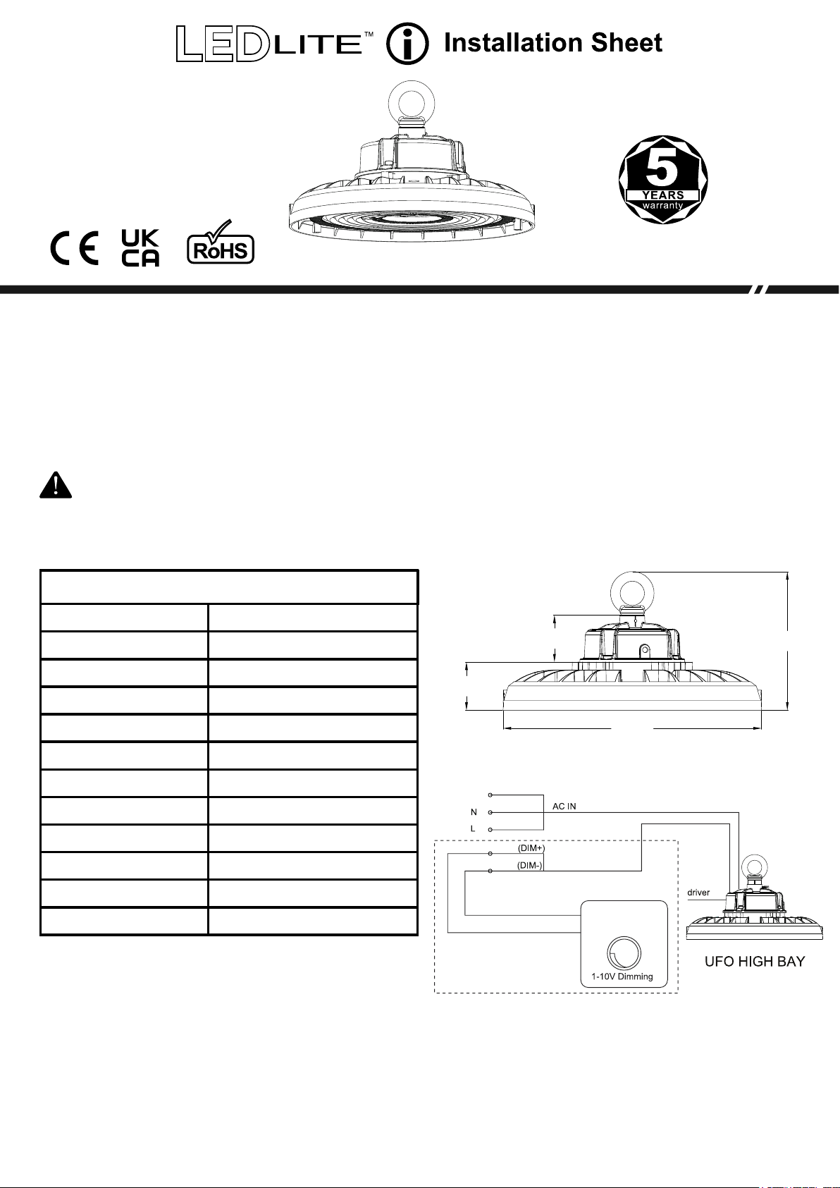
LTHB200CCT
LED High Bay 200W
CCT Changeable
IP65 220-240V
Please read these instructions before commencing installation & retain them for future reference.
Important information
It is recommended that 200W LED Highbay lights are installed by a qualified electrician ensuring the
installation complies to current IEE wiring regulations & local building control.
• These products are designed for connection to a 220-240V mains supply
• Any broken or damaged parts should be replaced as soon as possible
• We will not accept responsibility for any claims arising from a poor installation
ATTENTION:
• This high bay comes with 1-10V dimming function
• You can use the dimming cable (+/-) if you want to use the dimming function
• Ignore the dimming cable if you don't want to use this function
SPECIFICATIONS:
Part Number:
Power (W):
Luminous Flux (lm):
Input Voltage:
CCT Changeable:
Material:
CRI
Beam Angle:
Dimming:
Mounting:
Warranty:
IP Rating:
Installation Notice
LTHB200CCT
200W
30000-34000lm
220-240V/AC
3000K-4000K-5500K
Die-Cast Aluminium
>80
0
120
Fixed Output / 1-10V
Hanging / Wall (optional bracket)
5 Years
IP65
66mm
60mm
Wiring Diagram:
Yellow-Green
Earth
Blue
Brown
BLACK
GREY
Grey
Black
Only used if dimming
180mm
320mm
DC 1- 10V(- )
DC 1- 10V(+ )
• Always switch off mains supply before servicing
• Ensure 220-240V supply voltage
• Ensure correct wiring connection is made to input Live (Brown), Neutral (Blue) and Earth (Green and
Yellow) wires
• If dimming (1-10V dimming compatible), connect a suitable dimmer switch to the driver as per the
wiring diagram: Black wire is D+, Grey wire is D-
• LEDLITE recommends electrical connection to an RCD/RCBO protected lighting circuit
• After all electrical connections are finalised switch on electrical supply to test the light
Dimensions (mm):
Page 2
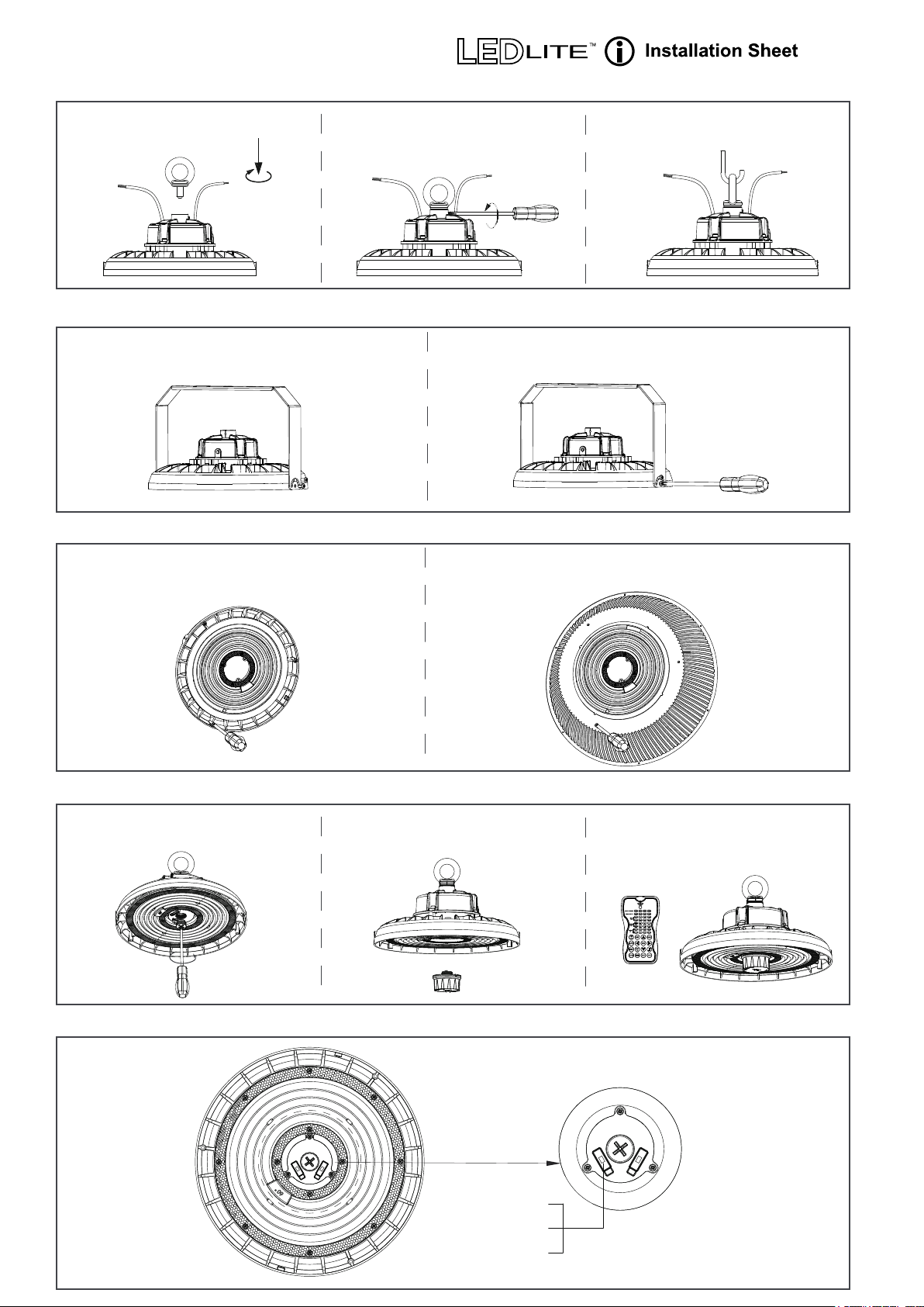
INSTALLATION INSTRUCTIONS:
a. Pole Mount Installation Procedure
LTHB200CCT
1. Install the hoop ring on the
power supply.
2. Tighten its side screws
using a screwdriver.
3. Install the high bay on the hook
or suspension cable.
b. U bracket Installation Procedure (optional extra - LTHBUB)
1. Align the bracket with the UFO High bay
0
c. 90 PC Reflector Installation Procedure (optional extra - LTHBREF)
1. Use a screwdriver to remove the reflector
screws from the high bay
2. Install the screws and tighten with a screwdriver
to finish the installation
2. Align the screw holes, insert the screws and tighten
the reflector using a screwdriver.
d. PIR Sensor Installation Procedure (optional extra - LTHBPIR)
1. Unscrew the sensor base plug. 2. Install the sensor on the sensor
base and tighten it.
e. CCT Adjustable function
Cool White (5500K)
Neutral White (4000K)
Warm White (3000K)
3. Use the remote control
to set up the sensor.
(optional extra - LTHBREM)
CCT Changeable
Switch
 Loading...