

Page 1
Emergency Lighting
Power Pack
for Mains Voltage LED Lamps
The product package contains the following:
• Emergency Light Unit
LTEM40
Please read this Manual prior to the installation and commissioning of the LTEM40.
The LTEM40 emergency pack is suitable for 5-20W LED lamps with internal Integrated Circuit (IC) driver (This device
CANNOT be used for LED lights with Resistive Circuit (RC) driver).
The LTEM40 emergency pack includes housing, PCB, battery and self-check test button with 3 colour LED indicator.
The battery is a Li-ion battery with a long lifespan; the PCB uses IC control design in charging/discharging and power
supply. The PCB circuit has built in protection for over-charging/discharging, output short-circuit, open circuit or
input/output reverse connection.
Operating principle:
The LTEM40 emergency pack charges when AC power is present. When fully charged, the circuit will protect the battery
from over-charging and the emergency pack will enter stand-by mode. As soon as the AC power fails the battery will
supply power to the LED lights.
Technical Specifications:
Working Voltage
Emergency Output
Voltage/Current
Emergency
Switching Time
Suitable for Lamps
Power (W)
Lamp Type
Charging Time
AC176-265V
DC 230V
0.03A-0.15A
≤5sec.
5-20W
LED Lamps
24h
Installation Standards:
• The installation of the LTEM40 must be done by a certified electrician according to the EN60598 part 1 and 2-22
as well as additional local standards (see basic wiring instructions on Page 2).
• The LTEM40 has no internal adjustments or serviceable parts and therefore the main cover should never be
removed.
• For installation in combination with a LED Driver, the wiring instructions in this manual must be followed or
the LTEM40 may not function as expected.
• The Status LED/Test Button should be positioned in such a way as to be easily visible under all circumstances to
ensure quick and convenient functionality check.
• The LTEM40 should be installed indoors (stairs, corridor, ceiling, etc.) and it is not for outdoor use.
Self-check function:
• Monthly inspection: The system simulates a power outage every 30 days for 35 seconds. It will quit and return to
the mains power state automatically if there is no fault.
• Annual inspection: The system simulates a power outage every 365 days and for 3 hours or until the battery power is
dissipated. It will quit and return to the mains power state automatically if there is no fault.
Battery Type
Battery Cycle
Use Times
Emergency Time
IP Rating
Luminous Flux
Weight
up to 1000 lumens
1
• 4000mAh 11.1V Li-Ion Battery
• Pre-wired Status LED/Self-test Button
• Instruction Manual
18650 Li-Ion
11.1V 4000mAh
≥500 times
≥180 minutes
IP30
0.39kg
Dimensions
Battery
Dimensions
Working
Temperature
Storage
Temperature
Warranty
Body Material
L158*W42*H25mm
L200*W36*H20mm
0 0
-5 C - +45 C
0 0
-5 C - +45 C
3 years
Fire Resistant PC
Battery Maintenance:
• Initial battery charge must be for a minimum of 24 hours before testing.
• To achieve best performance the LTEM40 must be properly maintained. The LTEM40 should be tested fully by
switching into emergency mode regularly in accordance with local testing regulations to check emergency operation
time (according to battery capacity). Any warranty claim must be accompanied by documentation which records the
dates of this maintenance procedure and signed by maintenance personnel.
Dimensions:
158mm 200mm
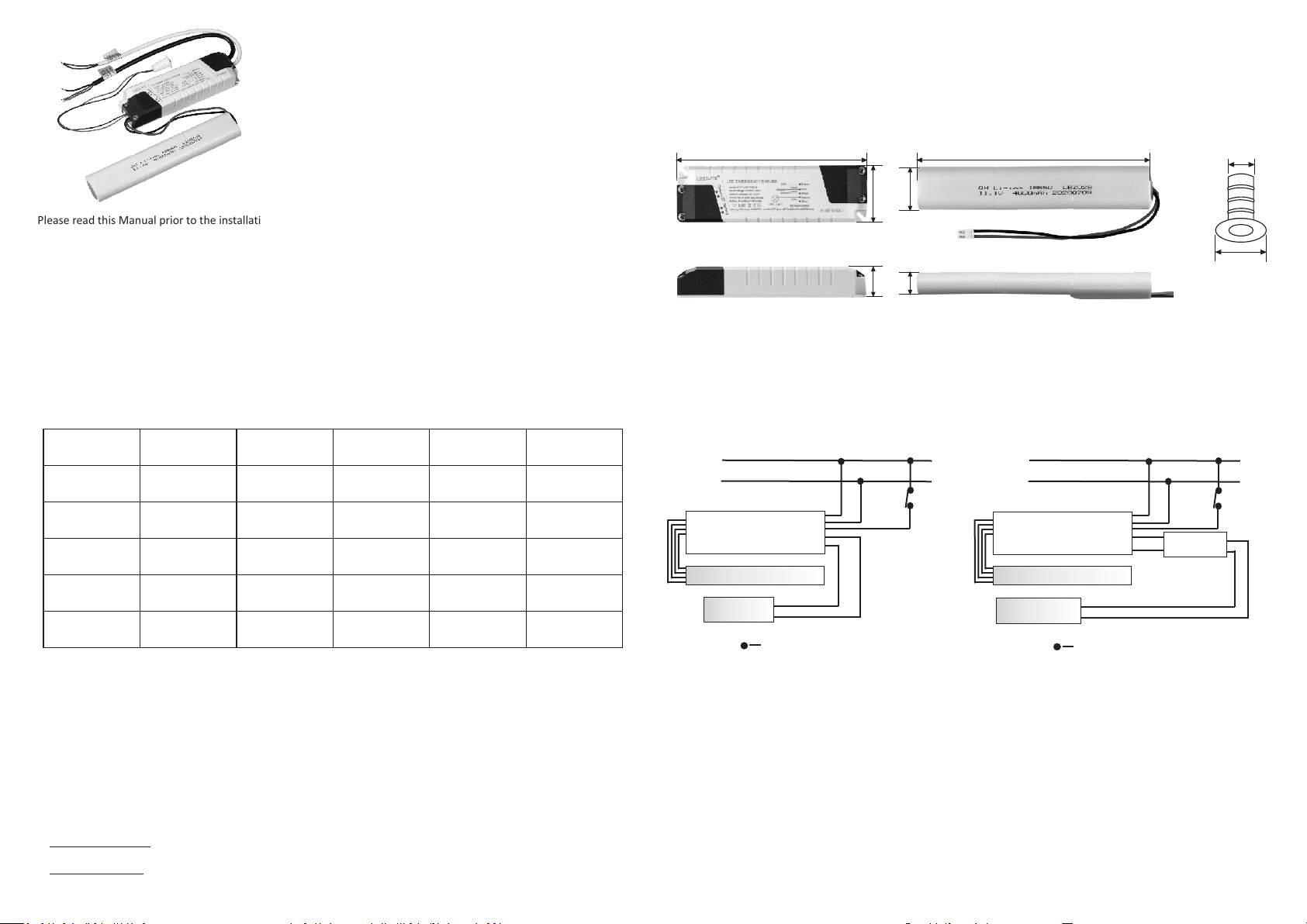
Fig. 1 Inverter Dimensions
42mm
25mm
36mm
20mm
Fig. 2 Battery Dimensions
Cut-out
ø12mm
ø22mm
Fig. 3 Status LED
Self-test Button
Dimensions
Installation and Wiring Instructions:
1. The LTEM40 emergency pack can be mounted on surfaces using the two installation holes. First mark the hole positions
and then use 4mm tapping screws to mount it on the surface. The product is safe to fit on materials combustible
above 200°C.
2.C onnect according to the wiring diagrams below observing the correct polarity where applicable.
WIRING DIAGRAMS
Switc h
LIV E
NEU TRAL
INP UT A C23 0V 50Hz
Emer ge nc y Driver
Batte ry
LED LIG HT
Ind icate s a conne ction
Fig. 5 - Wiring for LED Lights
with External Driver
LED D river
inp ut
INP UT A C23 0V 50Hz
Emerge nc y Driver
OUT PUT
Batte ry
LED LIG HTLED LIG HT
Ind icate s a conne ction
Fig. 4 - Wiring for LED Lights
with Internal Driver
3. When first connecting to AC power check if the LED lights work normally - the RED indicator light is ON until the
battery is fully charged.
4. Once the battery is charged the Green indicator light will be ON.
5. Turn the switch to the LED lights ON and OFF to check the correct function of the lights (if a switch is present).
6. Test the emergency mode:
a. Press the test button (status LED acts as the test button also) for 1 second and the emergency pack will switch into
power failure simulation mode (emergency mode). The indicator light for main power (Green) or for charging (Red)
will be OFF. Once the button is released it will return to normal AC power mode.
b. Cut off the emergency pack AC power - the LED lamp will be in emergency mode and the Green/Red indicator
light will be OFF.
After testing all the above steps the installation is finished.
Keep a record of maintenance and maintain the emergency pack and LED lamp regularly. Check regularly to ensure
its lifespan and usage.
2
Switc h
+
-
out put
LIV E
NEU TRAL
Page 2
Indicator Light and Test Button Functions:
RED
Indicator
Light
Function
Test Button
Function
Self-Test
Function
Fault
Detection
If the indicator lights are not working as expected or if the LED light does not work after turning the switch ON, the AC
power should be cut off immediately and the emergency driver should be checked.
GREEN
RED & GREEN
Manual Test
Manual Monthly
Inspection
Manual Annual
Inspection
Emergency Shutdown
Fault Removal
Monthly Inspection
Annual Inspection
Battery
Disconnected
Short-circuit of
charging circuit
Light Source
Disconnected
Light Source
Short-circuit
Insufficient
Discharge Time
When battery is charging: LED ON.
Full charged or emergency status: LED OFF.
Main power: LED ON; emergency status: LED OFF.
Monthly inspection status: fast flashing.
Annual inspection status: slowly flashing.
Battery fault: fast flashing.
Light source fault: slowly flashing.
Self-test status if battery not charged: long bright flashing.
Press the button for 1 second and release. The buzzer will ring simulating
emergency status.
Long press the button for 3-5 seconds. At the short buzzer ring release the button
to start monthly inspection; press once again to quit monthly inspection.
Long press the button for 5-7 seconds. At the long buzzer ring release the button
to start annual inspection; press once again to quit annual inspection.
In emergency state long press for more than 7 seconds or quickly press 2 times
for emergency shutdown.
After a fault is removed press the button once and the system enters normal state.
Every 30 days after installation the system will automatically switch to the
monthly inspection state. The duration is 35 seconds. If there is no fault it will
automatically exit and return to AC mains state.
Every 365 days after installation the system will automatically switch to the
annual inspection state. The duration is 3 hours . If there is no fault it will
automatically exit and return to AC mains state.
1. Battery open-circuit in Mains power status: Red and Green light fast flashing,
buzzer does not report failure. Will be auto restored after troubleshooting.
2. Battery open-circuit in Self-test status: Red and Green light fast flashing,
buzzer reported fault. Press test button to recover after troubleshooting.
1. Short-circuit in Mains power status: Red and Green light fast flashing, buzzer
does not report failure. Will be auto restored after troubleshooting.
2. Short-circuit in Self-test status: Red and Green light fast flashing, buzzer
reported fault. Press test button to recover after troubleshooting.
1. Light source open-circuit in Mains power status: no failure reported.
2. Light source open-circuit in Self-test status: Red and Green light slowly flashing,
buzzer reported fault. Press test button to recover after troubleshooting.
1. Light source short-circuit in Mains power status: no failure reported.
2. Light source short-circuit in Self-test status: Red and Green light slowly flashing,
buzzer reported fault. Press test button to recover after troubleshooting.
1. Monthly inspection status discharge time less than 35 seconds: Red and Green
light long bright flashing, buzzer reported fault.
2. The discharge time is less than 3 hours in the annual inspection status: Red
and Green light long bright flashing, buzzer reported fault.
Troubleshooting:
Most failures experienced are not due to the LTEM40 itself and are caused by improper installation or connection of
the unit. Please check that:
• Wires are properly clamped into terminals.
• Installation is done according to the wiring diagram.
• Proper polarities are observed.
• Proper LED load maximums are observed.
• The LED load has an IC driver (not RC).
In case of electromagnetic interference:
• Do not cross-wire the power input line and the light connection output line.
• When parallel wiring, a distance between 5 and 10 cm should be observed.
• Shorten the distance between the power supply input line and the device.
• When running in parallel, the connection between the power input line and the lamp should be as short as possible.
3 4
Lamp Type - LED
Tel:
Year 4 Year 5
Date Signed Date Signed Date
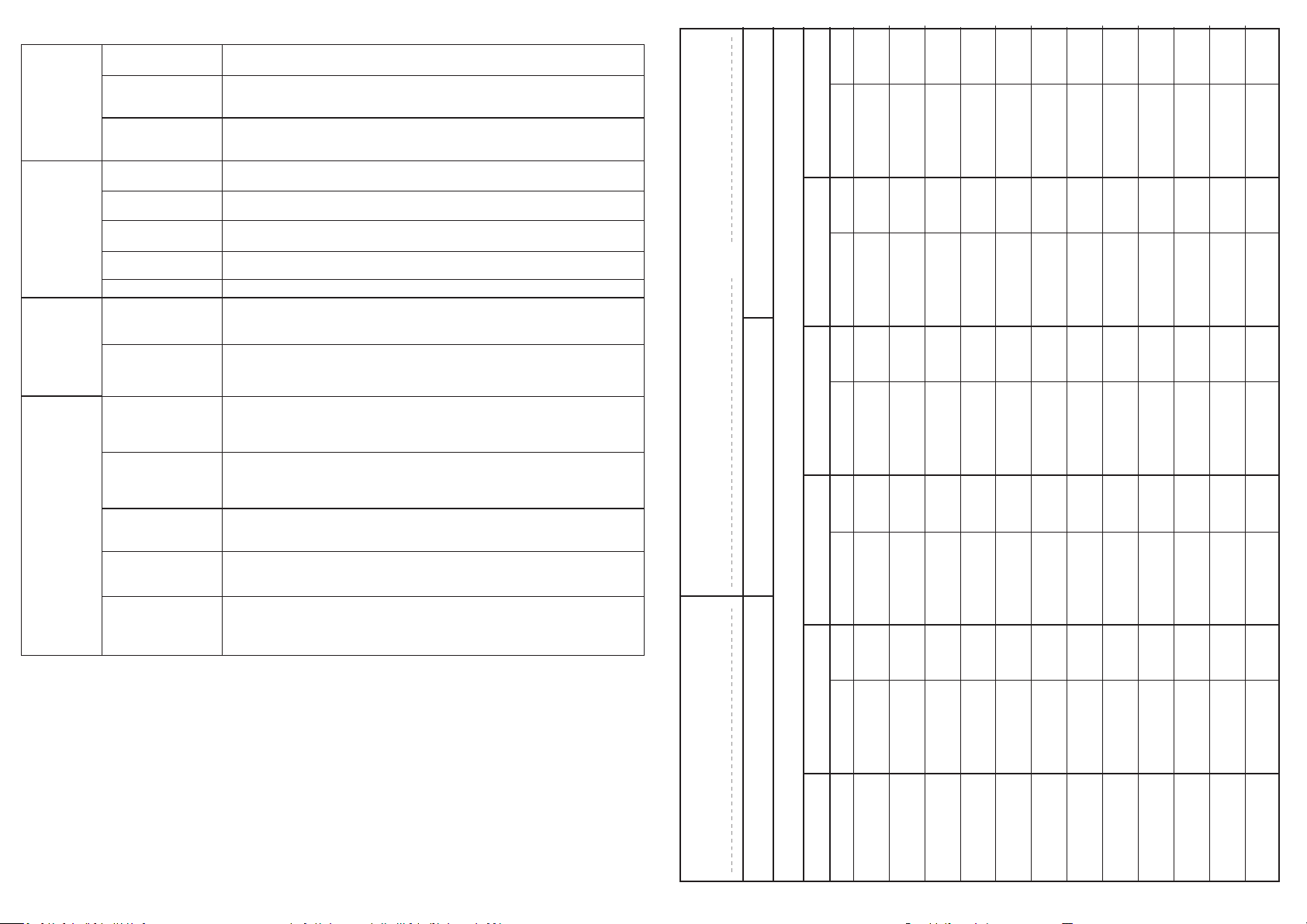
ROUTINE TEST RECORD
Year 1 Year 2 Year 3
Full Recharge Time 24 Hours Duration 3 Hours
Luminaire Ref/Location In Case of difficulty, contact the Installation Engineer:
Functional
Monthly Test Signed Date Signed Date Signed
Functional
Functional
Functional
Functional
Functional
Functional
Functional
Functional
Functional
Functional
Three Hour
 Loading...