

LD Systems Installation SUB 88A, Installation SAT 42 G2, Installation SAT 242W G2, Installation SAT 62AW G2, Installation SAT 62 G2 User Manual
...
USER´S MANUAL
BEDIENUNGSANLEITUNG
MANUEL D`UTILISATION
MANUAL DE USUARIO
INSTRUKCJA OBSŁUGI
MANUALE D‘ USO
LD SATG²/SUB series
PASSIVE INSTALLATION SPEAKER: LDsAT42G2(W) / LDsAT242G2(W) /
LDsAT62G2(W) / LDsAT82G2(W) / LDsUB88
POWERED INSTALLATION SPEAKER: LDsAT62AG2(W) / LDsUB88A / LDsUB10A

ENGLISHDEUTSCHFRANCAIS
You‘ve made the right choice!
We have designed this product to operate reliably over many years. LD Systems stands for this with its name and
many years of experience as a manufacturer of high-quality audio products.
Please read this User‘s Manual carefully, so that you can begin making optimum use of your LD Systems product
quickly.
You can find more information about LD SYSTEMS at our Internet site WWW.LD-SYSTEMS.COM
Introduction
The LD Systems SATG2 Series consists of ultracompact speakers that are suitable for smaller installations and
unobtrusive integration in practically any surroundings, e.g., in bars and restaurants, retail shops or even at
ESpAñoLpoLSKIITALIANo
home.
Four different passive 2-way speakers in various sizes and an active variant are available in black or white
cabinets. The series is rounded out by one passive and two active subwoofers.
FRANCAISFRANCAIS FRANCAISFRANCAIS
2

LD SATG²/SUB series
PASSIVE INSTALLATION SPEAKER: LDsAT42G2(W) / LDsAT242G2(W) /
LDsAT62G2(W) / LDsAT82G2(W) / LDsUB88
POWERED INSTALLATION SPEAKER: LDsAT62AG2(W) / LDsUB88A / LDsUB10A
FRANCAISFRANCAIS FRANCAISFRANCAIS
FRANCAISDEUTSCHENGLISH
ITALIANOPOLSKIESPAÑOL
3

PREVENTIVE MeAsUres:
1. Please read these instructions carefully.
2. Keep all information and instructions in a safe place.
3. Follow the instructions.
4. Observe all safety warnings. Never remove safety warnings or other information from the equipment.
5. Use the equipment only in the intended manner and for the intended purpose.
ENGLISHDEUTSCHFRANCAIS
6. Use only sufficiently stable and compatible stands and/or mounts (for fixed installations). Make certain that wall
mounts are properly installed and secured. Make certain that the equipment is installed securely and cannot fall down.
7. During installation, observ e the applicable safety regulations for your country.
8. Never install and operate the equipment near radiators, heat registers, ovens or other sources of heat. Make
certain that the equipment is always installed so that is cooled sufficiently and cannot overheat.
9. Never place sources of ignition, e.g., burning candles, on the equipment.
10. Ventilation slits must not be blocked.
11. Do not use this equipment in the immediate vicinity of water (does not apply to special outdoor equipment in this case, observe the special instructions noted below. Do not expose this equipment to flammable materials,
fluids or gases.
12. Make certain that dripping or splashed water cannot enter the equipment. Do not place containers filled with
liquids, such as vases or drinking vessels, on the equipment.
13. Make certain that objects cannot fall into the device.
14. Use this equipment only with the accessories recommended and intended by the manufacturer.
15. Do not open or modify this equipment.
16. After connecting the equipment, check all cables in order to prevent damage or accidents, e.g., due to
tripping hazards.
17. During transport, make certain that the equipment cannot fall down and possibly cause property damage and
personal injuries.
18. If your equipment is no longer functioning properly, if fluids or objects have gotten inside the equipment or
if it has been damaged in anot her way, switch it off immediately and unplug it from the mains outlet (if it is a
powered device). This equipment may only be repaired by authorized, qualified personnel.
19. Clean the equipment using a dry cloth.
ESpAñoLpoLSKIITALIANo
20. Comply with all applicable disposal laws in your country. During disposal of packaging, please separate
plastic and paper/cardboard.
21. Plastic bags must be kept out of reach of children.
FOR EQUIPMENT THAT CONNECTS TO THE POWER MAINS:
22. CAUTION: If the power cord of the device is equipped with an earthing contact, then it must be connected to
an outlet with a protective ground. Never deactivate the protective ground of a power cord.
FRANCAISFRANCAIS FRANCAISFRANCAIS
23. If the equipment has been exposed to strong fluctuations in temperature (for example, after transport), do
not switch it on immediately. Moisture and condensation could damage the equipment. Do not switch on the
equipment until it has reached room temperature.
24. Before connecting the equipment to the power outlet, first verify that the mains voltage and frequency match
the values specified on the equipment. If the equipment has a voltage selection switch, connect the equipment to
the power outlet only if the equipment values and the mains power values match. If the included power cord or
power adapter does not fit in your wall outlet, contact your electrician.
25. Do not step on the power cord. Make certain that the power cable does not become kinked, especially at the
mains outlet and/or power adapter and the equipment connector.
26. When connecting the equipment, make certain that the power cord or power adapter is always freely
accessible. Always disconnect the equipment from the power supply if the equipment is not in use or if you want
4

SAFETY:
to clean the equipment. Always unplug the power cord and power adapter from the power outlet at the plug or
adapter and not by pulling on the cord. Never touch the power cord and power adapter with wet hands.
27. Whenever possible, avoid switching the equipment on and off in quick succession because otherwise this
can shorten the useful life of the equipment.
28. IMPORTANT INFORMATION: Replace fuses only with fuses of the same type and rating. If a fuse blows repeatedly, please contact an authorised service centre.
29. To disconnect the equipment from the power mains completely, unplug the power cord or power adapter
from the power outlet.
30. If your device is equipped with a Volex power connector, the mating Volex equipment connector must be
unlocked before it can be removed. However, this also means that the equipment can slide and fall down if
the power cable is pulled, which can lead to personal injuries and/or other damage. For this reason, always be
careful when laying cables.
31. Unplug the power cord and power adapter from the power outlet if there is a risk of a lightning strike or
before extended periods of disuse.
CAUTION
RISK OF ELECTRIC SHOCK
DO NOT OPEN
CAUTION:
Never remove the cover, because otherwise there may be a risk of electric shock. There are no user serviceable
parts inside. Have repairs carried out only by qualified service personnel.
The lightning flash with arrowhead symbol within an equilateral triangle is intended to alert the user
to the presence of uninsulated “dangerous voltage” within the product’s enclosure that may be of
sufficient magnitude to constitute a risk of electrical shock.
The exclamation mark within an equilateral triangle is intended to alert the user to the presence of
important operating and maintenance instructions.
ENGLISH
FRANCAISFRANCAIS FRANCAISFRANCAIS
FRANCAISDEUTSCHENGLISH
CAUTION – HIGH VOLUME LEVELS WITH AUDIO PRODUCTS!
This equipment is intended for professional use. Therefore, commercial use of this equipment is subject to the
respectively applicable national accident prevention rules and regulations. As a manufacturer, Adam Hall is
obligated to notify you formally about the existence of potential health risks.
Hearing damage due to high volume and prolonged exposure: When in use, this product is capable of producing
high sound-pressure levels (SPL) that can lead to irreversible hearing damage in performers, employees, and
audience members. For this reason, avoid prolonged exposure to volumes in excess of 90 dB.
CAUTION! IMPORTANT INFORMATION ABOUT LIGHTING PRODUCTS
1. Do not look into the beam from a distance of less than 40 cm.
2. Do not stare into the beam for extended periods at short-to-medium distances.
3. Do not view the beam directly with optical instruments such as magnifiers.
4. Under some circumstances, stroboscopic effects may trigger epileptic seizures in sensitive individuals! For this
reason, persons who suffer from epilepsy should always avoid places where strobe lights are used.
ITALIANOPOLSKIESPAÑOL
5
OPERATING INSTRUCTIONS:
PASSIVE SPEAKERS
SAT42G2(W) and SAT62G2(W)
Up to four SAT42G2(W) or SAT62G2(W) speakers per power amplifier output can be operated in parallel at 4
ENGLISHDEUTSCHFRANCAIS
ohms. The speaker signal is simply looped through to the next speaker via the connector panel on the rear.
SAT242G2(W) and SAT82G2(W)
Up to two SAT42G2(W) or SAT62G2(W) speakers per power amplifier output can be operated in parallel at 4
ohms. The speaker signal is simply looped through to the next speaker via the connector panel on the rear.
SUB88 in conjunction with SAT42G2(W), SAT62G2(W), SAT242G2(W) or SAT82G2(W)
Connect the speaker cables from the power amplifier (Output Left and Right) to the Input Left and Right
connectors of the subwoofer.
Afterwards, connect the SAT Series speakers to the Output Left and Right connectors of the subwoofer.
Up to two SAT42G2(W) or SAT62G2(W) speakers per subwoofer output (Output Left and Right) can be operated in
parallel at 4 ohms.
One SAT242G2(W) or SAT82G2(W) speaker per subwoofer output (Output Left and Right) can be operated in this
configuration at 4 ohms.
We recommend using speaker cable with a conductor cross-section of at least 2 x 1.5 mm².
ACTIVE SPEAKERS
It is advisable to always turn on active speakers last and turn them off first in order to avoid the
switch-on noises caused by connected mixers, etc. If multiple active speakers are
connected one after the other in series (SAT62AG2), then they should always be switched on in the order in
which they are connected and switched off in reverse order.
ESpAñoLpoLSKIITALIANo
Turn the active speakers off before you connect them. They can be connected both via 6.3 mm
TRS plugs (balanced three-pole / unbalanced two-pole) as well as balanced three-pole XLR plugs
. Once you have connected all of the necessary cables and set the volume (MAIN LEVEL) of the active speaker to
minimum, you can switch on the audio source (e.g., mixer). Afterwards you can also switch on the active speakers. Start an audio signal and now turn the MAIN LEVEL knob clockwise until the desired volume is attained.
Carry out these steps with all connected active speakers.
On the following pages of this user manual, you will find a summary of the connectors, controls, and indicators.
FRANCAISFRANCAIS FRANCAISFRANCAIS
6

OPERATING INSTRUCTIONS :
SUB 10A in conjunction with passive SAT Series speakers
Connect the passive SAT Series speakers to the speaker outputs (SPEAKER OUT LEFT / RIGHT) of the SUB10A.
Up to four SAT42G2(W) or SAT62G2(W) speakers per speaker output can be operated in parallel.
The speaker signal is simply looped through to the next speaker via the connector panel on the rear of the
passive speaker.
Up to two SAT242G2(W) or SAT862G2(W) speakers per speaker output can be operated in parallel.
The speaker signal is simply looped through to the next speaker via the connector panel on the rear of the
passive speaker.
We recommend using speaker cable with a conductor cross-section of at least 2 x 1.5 mm².
SUB10A in conjunction with SAT62AG2(W) active speakers
Connect the active speakers to the line outputs (LINE DIRECT OUTPUT) of the SUB10A.
LOOPING THROUGH THE SIGNAL
With the SAT62AG2(W) active speakers, the audio signal can be looped through to additional systems using a
three-pole XLR cable
. Accordingly, it is not necessary to connect each device to the audio source individually. Please
use high-quality XLR cables for this and ensure that they are connected carefully.
SUB88A
To connect the SUB88A active subwoofer to the SAT62AG2 active speakers, the subwoofer must be connected as
the last speaker in the chain, since it only has one line input.
FRANCAISFRANCAIS FRANCAISFRANCAIS
FRANCAISDEUTSCHENGLISH
ITALIANOPOLSKIESPAÑOL
7

CONNECTORS, conTroLs, AnD inDicATors:
LDSAT62AG2(W):
(LDSAT62AG2 shown)
ENGLISHDEUTSCHFRANCAIS
ESpAñoLpoLSKIITALIANo
FRANCAISFRANCAIS FRANCAISFRANCAIS
5
6
7
4
3
21
1
POWER SOCKET
IEC power socket 220V-240V with built-in fuse
holder.
IMPORTANT INFORMATION: Replace the fuse only
with a fuse of the same type and rating. If the fuse
blows repeatedly, please contact an authorised
service centre.
2
POWER
On / off switch. Before switching the active
speaker on or off, always adjust the volume to
zero (MAIN LEVEL all the way to the left).
3
BALANCED LINE INPUT
Balanced line input (XLR / 6.3 mm TRS combo) for
connecting an external audio source (e.g., mixer).
4
DIRECT OUT
Balanced XLR line output for looping through the
input signal.
5
MAIN LEVEL
Volume control
6
POWER MODE
Toggles between continuous operation (ON) and
auto mode (AUTO). In the AUTO position, the
amplifier of the speaker system switches on automatically as soon as a signal is received. If there
is no signal for several minutes, the amplifier
switches to standy mode.
7
POWER LED
The LED lights up red if the unit is switched on
and is in AUTO mode, but no signal is present.
Once a signal is present, the LED changes colours
to green.
The LED also lights up green if the unit is
switched on and is in ON mode.
8

CONNECTORS, conTroLs, AnD inDicATors:
1
2
3
4 4
5 5
7
6
8
LDSUB10A:
1
MAIN LEVEL
Overall volume of the system (subwoofer and
connected passive speakers).
2
SUB PHASE
Phase reverse switch for the subwoofer (0°/180°).
3
SUB LEVEL
Sets the relative volume of subwoofers and
satellite speakers.
4
LINE DIRECT OUTPUT (LEFT / RIGHT)
Balanced XLR line output (left / right) for looping
through the input signal.
5
LINE INPUT XLR (LEFT / RIGHT)
Balanced line input (XLR / 6.3 mm TRS combo, left
/ right) for connecting an external audio source
(e.g., mixer).
6
SPEAKER OUT (LEFT / RIGHT)
Terminal posts for speaker cables. Connection of
speakers or speaker systems with a total
impedance of at least 4 ohms per channel.
Connect the positive pole (+) of the speaker cable
to the red terminal clamp (+) and the negative
pole (-) of the speaker cable to the black terminal
clamp (-) of the respective channel. Optionally,
speaker cables with banana plugs can also be
used.
7
POWER SOCKET
IEC power socket 220V-240V with built-in fuse holder.
IMPORTANT INFORMATION: Replace the fuse only
with a fuse of the same type and rating. If the fuse
blows repeatedly, please contact an authorised
service centre.
8
POWER
On / off switch. Before switching the active speaker on or off, always adjust the volume to zero
(MAIN LEVEL all the way to the left).
FRANCAISFRANCAIS FRANCAISFRANCAIS
FRANCAISDEUTSCHENGLISH
ITALIANOPOLSKIESPAÑOL
9
CONNECTORS, conTroLs, AnD inDicATors:
ENGLISHDEUTSCHFRANCAIS
4
5
9
8
7
ESpAñoLpoLSKIITALIANo
FRANCAISFRANCAIS FRANCAISFRANCAIS
6
2
1
3
10

CONNECTORS, conTroLs, AnD inDicATors:
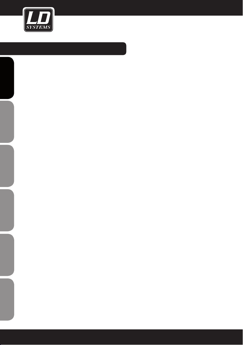
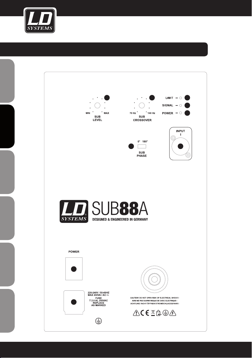
LDSUB88A:
1
POWER SOCKET
IEC power socket 220V-240V with built-in fuse holder.
IMPORTANT INFORMATION: Replace the fuse only with a fuse of the same type and rating. If the fuse blows
repeatedly, please contact an authorised service centre.
2
POWER
On / off switch. Before switching the active speaker on or off, always adjust the volume to zero (SUB LEVEL
all the way to the left).
3
BALANCED LINE INPUT
Balanced line input (XLR / 6.3 mm TRS combo) for connecting an external audio source (e.g., mixer).
4
SUB LEVEL
Volume control
5
SUB CROSSOVER
Variable low-pass filter 70 - 140 Hz. Controls the lower limit frequency of the subwoofer.
6
SUB PHASE
Phase reverse switch for the subwoofer (0°, 180°).
7
POWER LED
Lights up when the subwoofer is switched on and properly connected to the power mains.
FRANCAISFRANCAIS FRANCAISFRANCAIS
FRANCAISDEUTSCHENGLISH
8
SIGNAL LED
The LED lights up when an audio signal is present at the line input.
9
LIMIT LED
Lights up if the speaker is operating in the clipping range. Brief flashing is not a cause for concern, since
the internal audio limiter compensates for over-modulation. Permanent illumination should be avoided by
reducing the input level.
ITALIANOPOLSKIESPAÑOL
11
CONNECTORS, conTroLs, AnD inDicATors:
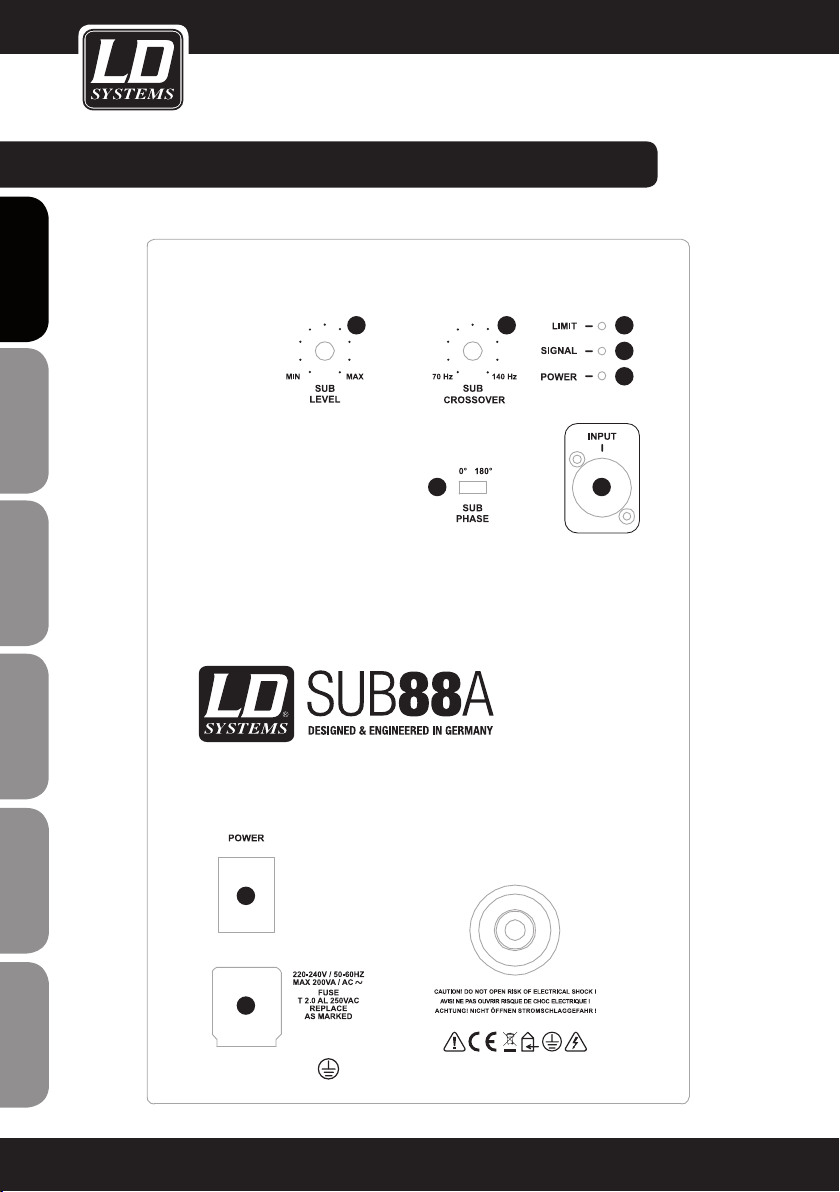
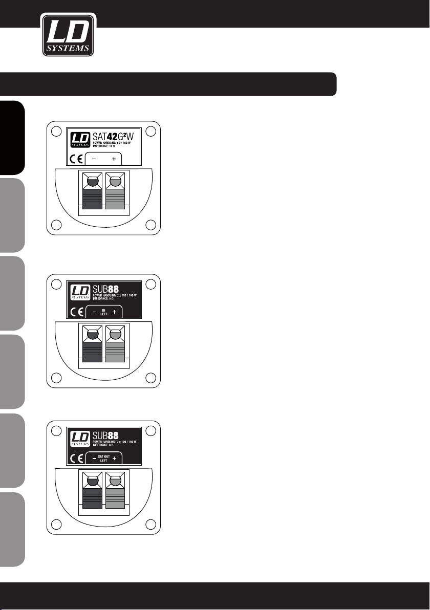
LDSATG2 PASSIVE SPEAKER:
(LDSAT42G2W shown)
ENGLISHDEUTSCHFRANCAIS
ESpAñoLpoLSKIITALIANo
TERMINAL CLAMPS FOR SPEAKER CABLES
Connect the positive pole (+) of the speaker cable
coming from the amplifier to the red terminal clamp (+)
and the negative pole (-) of the speaker cable coming
from the amplifier to the black terminal clamp (-).
LDSUB88 PASSIVE SUBWOOFER:
SUB88 IN (IN LEFT shown)
Terminal clamps for speaker cables.
Connect the positive pole (OUTPUT LEFT +) of the
speaker cable coming from the amplifier to the red
terminal clamp (IN LEFT +) and the negative pole
(OUTPUT LEFT -) of the speaker cable coming from
the amplifier to the black terminal clamp (IN LEFT -) of
the subwoofer.
Connect the SUB88 IN RIGHT and the amplifier OUTPUT RIGHT in the same manner.
FRANCAISFRANCAIS FRANCAISFRANCAIS
12
SUB88 SAT OUT (SAT OUT LEFT shown)
Terminal clamps for speaker cables.
Connect the positive pole (+) of the speaker cable
to the red terminal clamp (SAT OUT LEFT +) and the
negative pole (-) of the speaker cable to the black
terminal clamp (SAT OUT LEFT -) of the respective
channel.
Connect the SATG2 Series speakers to the other side
of the speaker cable in the same manner.
IMPORTANT: Observe the remarks rearding the
LDSUB88 subwoofer and the passive LDSATG2 Series
speakers in the "OPERATING INSTRUCTIONS" section
of this user manual!
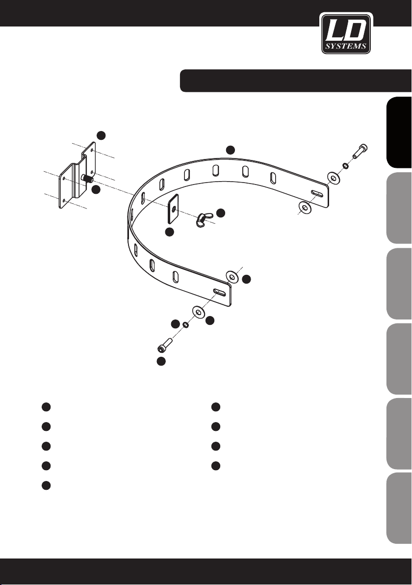
SPEAKER MOUNT incLUDeD:CONNECTORS, conTroLs, AnD inDicATors:
1
3
2
1
WALL BRACKET
2
M6 BOLT
3
U-SHAPED MOUNTING BRACKET
4
WASHER
FRANCAISFRANCAIS FRANCAISFRANCAIS
5
4
FRANCAISDEUTSCHENGLISH
6
8
7
9
6
RUBBER WASHER
7
M6 SOCKET SCREW x 16
8
SPRING WASHER
9
WASHER
5
M6 WINGNUT
NOTE: Speaker brackets for wall mounting are included with all SATG2 Series speakers. With the LDSAT242G2(W)
speaker, a bracket for horizontal mounting is included in addition to the bracket for vertical mounting.
ITALIANOPOLSKIESPAÑOL
13

COMBINATION eXAMPLes:
1 X LDSUB10A + 2 X 4 LDSAT42G2(W)
ENGLISHDEUTSCHFRANCAIS
ESpAñoLpoLSKIITALIANo
FRANCAISFRANCAIS FRANCAISFRANCAIS
14
SPEAKER OUT LEFT SPEAKER OUT RIGHT

COMBINATION eXAMPLes:COMBINATION eXAMPLes:
1 X LDSUB10A + 2 X 2 LDSAT242G2(W)
FRANCAISFRANCAIS FRANCAISFRANCAIS
FRANCAISDEUTSCHENGLISH
SPEAKER OUT LEFT SPEAKER OUT RIGHT
ITALIANOPOLSKIESPAÑOL
15
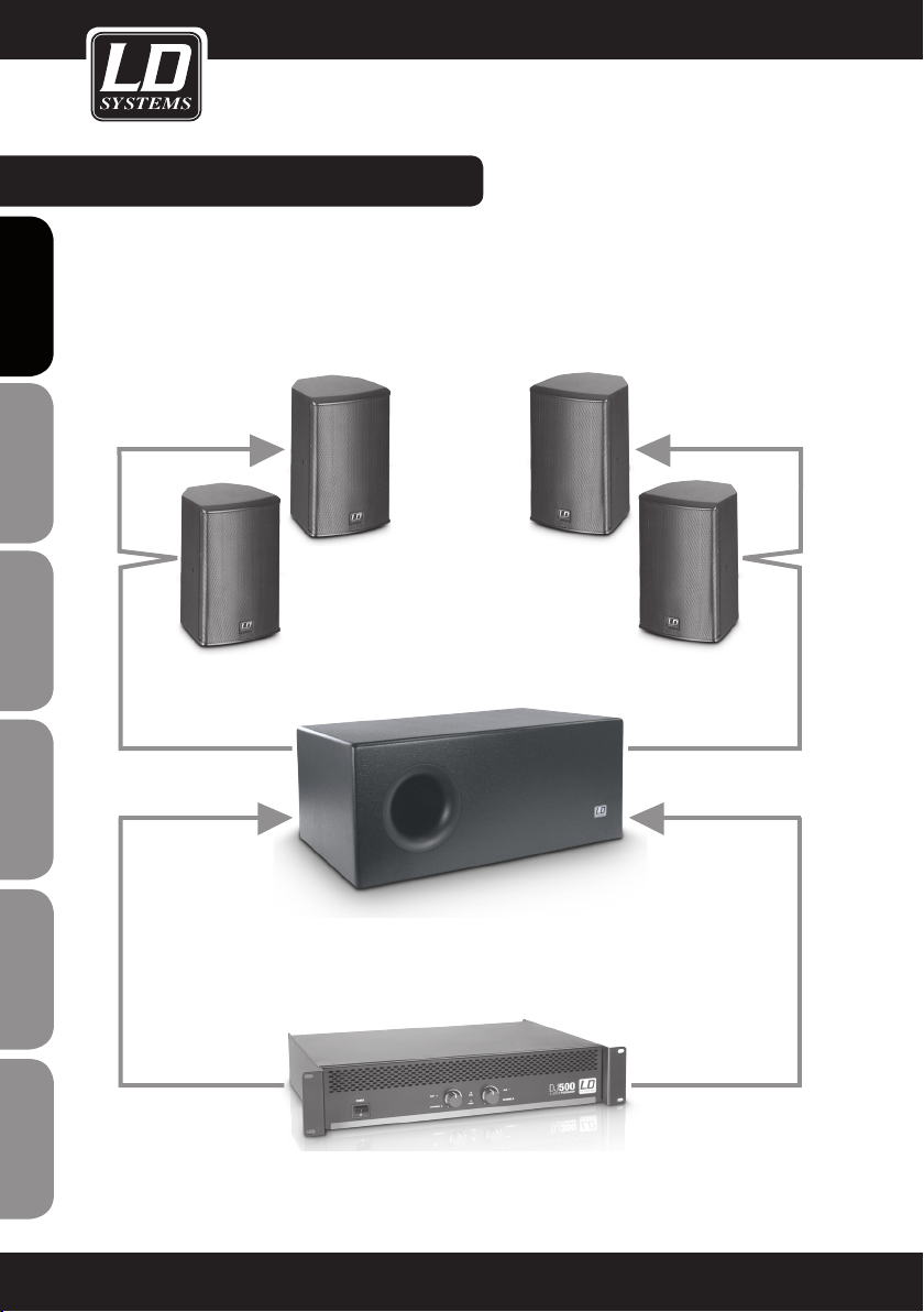
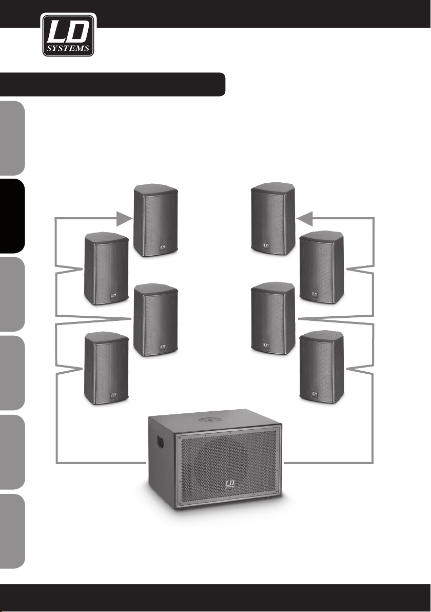
COMBINATION eXAMPLes:
1 X LDDJ500 + 1X LDSUB88 + 2 X 2 LDSAT62G2(W) )
ENGLISHDEUTSCHFRANCAIS
SAT OUT LEFT SAT OUT RIGHT
ESpAñoLpoLSKIITALIANo
FRANCAISFRANCAIS FRANCAISFRANCAIS
16
SUB88 IN LEFT SUB88 IN RIGHT
SPEAKER OUT LEFT SPEAKER OUT RIGHT

SUWMB10B (BLACK)
SUWMB10W (WHITE)
Universal speaker wall bracket with safety rope. Four snap-lock joints permit mounting of the speaker in virtually
any position.
Maximum load: 10 kg
FRANCAISFRANCAIS FRANCAISFRANCAIS
FRANCAISDEUTSCHENGLISH
ITALIANOPOLSKIESPAÑOL
17

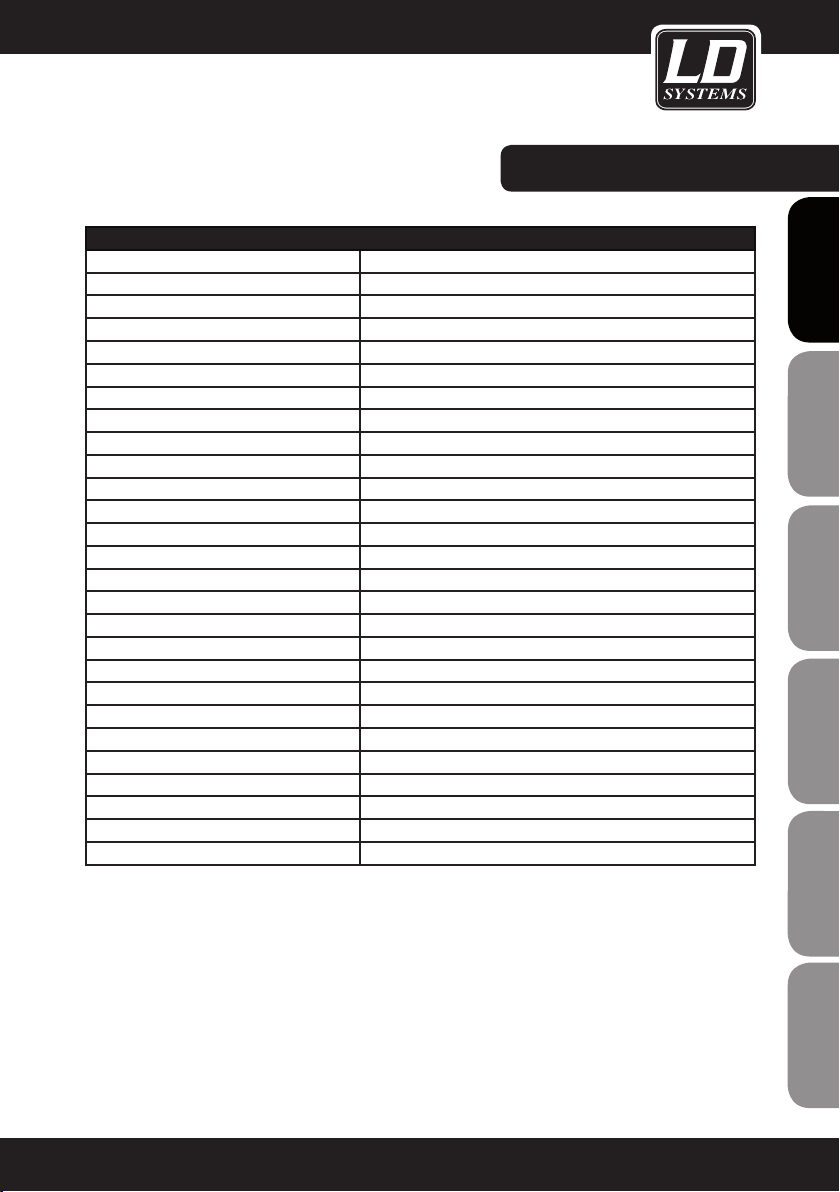
SPECIFICATIONS:
LDSAT42G2(W)
Product type Installation Speakers
ENGLISHDEUTSCHFRANCAIS
ESpAñoLpoLSKIITALIANo
Type: passive
Woofer size: 4 "
Woofer size: 101 mm
Woofer magnet: ferrite
Woofer brand: custom made
HF driver size: 1 "
HF driver size: 25 mm
HF driver magnet: ferrite
HF driver brand: custom made
Dispersion angle (H x V): 60 x 60 °
Power output (RMS): 60 W
Power output (peak): 100 W
Frequency response: 75 Hz - 20,000 Hz
Sound-pressure level (1 W/1 m): 85 dB
Max SPL: 103 dB
Impedance: 16 ohms
Protection: HF driver
Speaker inputs: 1
Speaker input connections: Clamp connector
Cabinet material: 12 mm MDF
Cabinet surface: textured coating
Cabinet colour: black (LDSAT42G2) / white (LDSAT42G2W)
Cabinet type: closed
Dimensions (W x H x D): 140 x 230 x 125 mm
Weight: 5 kg / pair
Other features: Wall bracket included
FRANCAISFRANCAIS FRANCAISFRANCAIS
18

SPECIFICATIONS:
LDSAT242G2(W)
Product type: Installation Speakers
Type: passive
Woofer size: 2 x 4"
Woofer size: 2 x 101 mm
Woofer magnet: ferrite
Woofer brand: custom made
HF driver size: 1 "
HF driver size: 25 mm
HF driver magnet: ferrite
HF driver brand: custom made
Dispersion angle (H x V): 60 x 60 °
Power output (RMS): 100 W
Power output (peak): 180 W
Frequency response: 75 Hz - 20,000 Hz
Sound-pressure level (1 W/1 m): 88 dB
Max SPL: 108 dB
Impedance: 8 ohms
Protection: HF driver
Speaker inputs: 1
Speaker input connections: Clamp connector
Cabinet material: 12 mm MDF
Cabinet surface: textured coating
Cabinet colour: black (LDSAT242G2) / white (LDSAT242G2W)
Cabinet type: closed
Dimensions (W x H x D): 140 x 378 x 135 mm
Weight: 4.15 kg
Other features: Wall bracket included
FRANCAISFRANCAIS FRANCAISFRANCAIS
FRANCAISDEUTSCHENGLISH
ITALIANOPOLSKIESPAÑOL
19

SPECIFICATIONS:
LDSAT62G2(W)
Product type: Installation Speakers
ENGLISHDEUTSCHFRANCAIS
ESpAñoLpoLSKIITALIANo
Type: passive
Woofer size: 6,5 "
Woofer size: 165 mm
Woofer magnet: ferrite
Woofer brand: custom made
HF driver size: 1 "
HF driver size: 25 mm
HF driver magnet: ferrite
HF driver brand: custom made
Dispersion angle (H x V): 60 x 60 °
Power output (RMS): 80 W
Power output (peak): 130 W
Frequency response: 55 Hz - 20,000 Hz
Sound-pressure level (1 W/1 m): 89 dB
Max SPL: 108 dB
Impedance: 16 ohms
Protection: HF driver
Speaker inputs: 1
Speaker input connections: Clamp connector
Cabinet material: 12 mm MDF
Cabinet surface: textured coating
Cabinet colour: black (LDSAT62G2) / white (LDSAT62G2W)
Cabinet type: bass reflex
Dimensions (W x H x D): 200 x 320 x 200 mm
Weight: 8.2 kg / pair
Other features: Wall bracket included
FRANCAISFRANCAIS FRANCAISFRANCAIS
20
SPECIFICATIONS:
LDSAT82G2(W)
Product type: Installation Speakers
Type: passive
Woofer size: 8 "
Woofer size: 203 mm
Woofer magnet: ferrite
Woofer brand: custom made
HF driver size: 1 "
HF driver size: 25 mm
HF driver magnet: ferrite
HF driver brand: custom made
Dispersion angle (H x V): 60 x 60 °
Power output (RMS): 120 W
Power output (peak): 200 W
Frequency response: 50 Hz - 20,000 Hz
Sound-pressure level (1 W/1 m): 93 dB
Max SPL: 114 dB
Impedance: 8 ohms
Protection: HF driver
Speaker inputs: 1
Speaker input connections: Clamp connector
Cabinet material: 15 mm MDF
Cabinet surface: textured coating
Cabinet colour: black (LDSAT82G2) / white (LDSAT82G2W)
Cabinet type: bass reflex
Dimensions (W x H x D): 274 x 410 x 243 mm
Weight 7 kg
Other features: Wall bracket included
FRANCAISFRANCAIS FRANCAISFRANCAIS
FRANCAISDEUTSCHENGLISH
ITALIANOPOLSKIESPAÑOL
21

SPECIFICATIONS:
LDSUB88
Product type: Installation Subwoofers
ENGLISHDEUTSCHFRANCAIS
ESpAñoLpoLSKIITALIANo
Type: passive
Woofer size: 2 x 8"
Woofer size: 2 x 203 mm
Woofer magnet: ferrite
Woofer brand: custom made
Power output (RMS): 2 x 100 W
Power output (peak): 2 x 180 W
Frequency response: 40 Hz - 120 Hz
Sound-pressure level (1 W/1 m): 92 dB
Max SPL: 115 dB
Impedance: 2 x 8 ohms
Speaker inputs: 2
Speaker input connections: Clamp connector
Speaker outputs: 2
Speaker output connections: Clamp connector
Cabinet material: 15 mm MDF
Cabinet surface: textured coating
Cabinet colour: black
Cabinet type: band pass
Dimensions (W x H x D): 600 x 250 x 350 mm
Weight: 13.3 kg
Other features: internal low-pass filter (120 Hz)
FRANCAISFRANCAIS FRANCAISFRANCAIS
22

SPECIFICATIONS:
LDSAT62AG2(W)
Product type: Installation Speakers
Type: active
Woofer size: 6,5 "
Woofer size: 165 mm
Woofer magnet: ferrite
Woofer brand: custom made
HF driver size: 1 "
HF driver size: 25 mm
HF driver magnet: ferrite
HF driver brand: custom made
Amplifier: Class A/B
Dispersion angle (H x V): 60 x 60 °
Power output (RMS): 50 W
Frequency response: 55 Hz - 20,000 Hz
Max SPL: 108 dB
Protection: HF driver, overcurrent
Controls: Power switch (on/off), volume control, switchable auto-power
mode
Indicators: Power
Line input connectors: XLR, 6.3 mm TRS (combo)
Line output connectors: XLR
Power supply: transformer
Operating voltage: 220 V AC - 240 V AC, 50 - 60 Hz
Power consumption (max.) 80 VA
Cabinet material: 12 mm MDF
Cabinet surface: textured coating
Cabinet colour: black (LDSAT62AG2) / white (LDSAT62AG2W)
Cabinet type: bass reflex
Dimensions (W x H x D): 200 x 320 x 200 mm
Weight: 5.25 kg
Other features: Wall bracket included
FRANCAISFRANCAIS FRANCAISFRANCAIS
FRANCAISDEUTSCHENGLISH
ITALIANOPOLSKIESPAÑOL
23

SPECIFICATIONS:
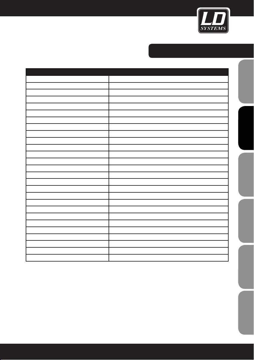
LDSUB88A
Product type: Installation Subwoofers
ENGLISHDEUTSCHFRANCAIS
ESpAñoLpoLSKIITALIANo
Type: active
Woofer size: 2 x 8"
Woofer size: 2 x 203 mm
Woofer magnet: ferrite
Woofer brand: custom made
Amplifier: Class A/B
Power output (RMS): 150 W
Frequency response: 40 Hz - 120 Hz
Sound-pressure level (1 W/1 m): 92 dB
Max SPL: 115 dB
Protection: overload
Controls: Phase 180°, volume, low-pass filter (70 - 140 Hz)
Indicators: Limit, Signal, Power
Line inputs: 1
Line input connectors: XLR, 6.3 mm TRS (combo)
Power supply: transformer
Operating voltage: 220 V AC - 240 V AC, 50 - 60 Hz
Power consumption (max.): 200 VA
Cabinet material: 15 mm MDF
Cabinet surface: textured coating
Cabinet colour: black
Cabinet type: band pass
Dimensions (W x H x D): 600 x 250 x 350 mm
Weight: 15 kg
FRANCAISFRANCAIS FRANCAISFRANCAIS
24

SPECIFICATIONS:
LDSUB10A
Product type: PA subwoofer
Type: active
Woofer size: 10 "
Woofer size: 254 mm
Woofer magnet: ferrite
Woofer brand: custom made
Woofer voice coil: 2 "
Woofer voice coil: 50.8 mm
Amplifier: Class A/B
Power output (RMS): 3 x 120 W
Power output (peak): 3 x 240 W
Subwoofer frequency range: 40 Hz - 120 Hz
Max. SPL (continuous): 118 dB
Protection: overcurrent, limiter, short-circuit
Input sensitivity: 0.3 V RMS
Controls: Subwoofer volume, power switch (on/off), volume, subwoofer
phase reverse
Indicators: Power
Line inputs: 2
Line input connectors: 6.3 mm TRS, XLR
Line outputs: 2 x Direct Output
Line output connectors: XLR
Speaker outputs: 2
Speaker output connections: Terminal posts
Power supply: transformer
Operating voltage: 220 V AC - 240 V AC, 50 - 60 Hz
Power consumption (max.): 600 VA
Cabinet material: 15 mm MDF
Cabinet surface: textured coating
Cabinet type: bass reflex
Dimensions (W x H x D): 505 x 345 x 425 mm
Weight: 21 kg
Other features: M20 threaded flange, ergonomic recessed handles, speaker
outputs with high-pass filter (170 Hz, -18 dB)
FRANCAISFRANCAIS FRANCAISFRANCAIS
FRANCAISDEUTSCHENGLISH
ITALIANOPOLSKIESPAÑOL
25
MANUFACTURER´S DecLArATions:
MANUFACTURER‘S WARRANTY
This warranty covers the Adam Hall, LD Systems, Defender, Palmer, and Cameo brands.
It applies to all products distributed by Adam Hall.
ENGLISHDEUTSCHFRANCAIS
This warranty declaration does not affect the statutory warranty claims against the manufacturer, but expands
them with additional warranty claims vis-a-vis Adam Hall.
Adam Hall warrants that the Adam Hall product that you have purchased from Adam Hall or from an Adam Hall
authorized reseller is free from defects in materials or workmanship under normal use for a period of 2 or 5 years
(please inquire on a product-by-product basis) from the date of purchase.
The warranty period begins on the date on which the product was purchased, proof of which must be produced
(through presentation of the invoice or the delivery note with the date of purchase) in the event of a warranty claim.
Should products of the brands named above be in need of repair within the limited warranty period, you are entitled
to warranty service according to the terms and conditions stated here.
During the Limited Warranty Period, Adam Hall will repair or replace the defective component parts or the product.
In the event of repair or replacement during the Limited Warranty Period, the replaced original parts and/or products become property of Adam Hall.
In the unlikely event that the product which you purchased has a recurring failure, Adam Hall has the right, at its
discretion, to replace the defective product with another product, provided that the new product is at least equivalent to the product being replaced with regard to the technical specifications.
Adam Hall does not warrant that the operation of this product will be uninterrupted or error-free. Adam Hall is not
responsible for damage that occurs as a result of your failure to follow the instructions included with the Adam Hall
branded product. The manufacturer‘s warranty does not cover – expendable parts (e. g., rechargeable batteries)
ESpAñoLpoLSKIITALIANo
- products from which the serial number has been removed or with a serial number that has been damaged as a
result of an accident - damage due to improper use, user error or other external reasons
- damage to devices operated outside the usage parameters stated in the documentation included with the product
- damage due to the use of replacement parts not manufactured, sold or recommended by Adam Hall,
- damage due to modification or servicing by anyone other than Adam Hall.
These terms and conditions constitute the complete and exclusive warranty agreement between you and Adam
Hall regarding the Adam Hall branded product you have purchased.
FRANCAISFRANCAIS FRANCAISFRANCAIS
26

MANUFACTURER´S DecLArATions:
LIMITATION OF LIABILITY
If your Adam Hall branded hardware product fails to work as warranted above, your sole and exclusive remedy
shall be repair or replacement. Adam Halls’ maximum liability under this limited warranty is expressly limited to
the lesser of the price you have paid for the product or the cost of repair or replacement of any components that
malfunction under conditions of normal use.
Adam Hall is not liable for any damages caused by the product or the failure of the product, including any lost
profits or savings or special, incidental, or consequential damages. Adam Hall is not liable for any claim made by
a third party or made by you for a third party.
This limitation of liability applies whether damages are sought, or claims are made, under this Limited Warranty
or as a tort claim (including negligence and strict product liability), a contract claim, or any other claim, and
cannot be rescinded or changed by anyone. This limitation of liability will be effective even if you have advised
Adam Hall or an authorized representative of Adam Hall of the possibility of any such damages, but not, however,
in the event of claims for damages in connection with personal injuries.
This manufacturer‘s warranty grants you specific rights; depending on jurisdiction (nation or state), you may be
be entitled to additional claims. You are advised to consult applicable state or national laws for a full determination of your rights.
REQUESTING WARRANTY SERVICE
To request warranty service for the product, contact Adam Hall or the Adam Hall authorized reseller from which
you purchased the product.
FRANCAISFRANCAIS FRANCAISFRANCAIS
FRANCAISDEUTSCHENGLISH
EC DECLARATION oF conForMiTY
The equipment marketed by Adam Hall complies (where applicable) with the essential requirements and other
relevant specifications of Directives 1999/5/EC (R&TTE), 2004/108/EC (EMC) und 2006/95/EC (LVD). Additional
information can be found at www.adamhall.com.
ITALIANOPOLSKIESPAÑOL
27

MANUFACTURER´S DecLArATions:
PROPER DISPOSAL OF THIS PRODUCT
(Valid in the European Union and other European countries with waste separation)
This symbol on the product, or the documents accompanying the product, indicates that this appliance may not
ENGLISHDEUTSCHFRANCAIS
be treated as household waste. This is to avoid environmental damage or personal injury due to uncontrolled
waste disposal. Please dispose of this product separately from other waste and have it recycled to promote
sustainable economic activity.
Household users should contact either the retailer where they purchased this product, or their local government
office, for details on where and how they can recycle this item in an environmentally friendly manner.
Business users should contact their supplier and check the terms and conditions of the purchase contract. This
product should not be mixed with other commercial wastes for disposal .
ENVIRONMENTAL PROTECTION AND ENERGY conserVATion
Energy conservation is an active contribution to environmental protection. Please turn off all unneeded electrical
devices. To prevent unneeded devices from consuming power in standby mode, disconnect the mains plug.
ESpAñoLpoLSKIITALIANo
FRANCAISFRANCAIS FRANCAISFRANCAIS
Adam Hall GmbH, all rights reserved. The technical data and the functional product characteristics can be subject
to modifications. The photocopying, the translation, and all other forms of copying of fragments or of the integrlity
of this user’s manual is prohibited.
28

FRANCAISFRANCAIS FRANCAISFRANCAIS
FRANCAISDEUTSCHENGLISH
ITALIANOPOLSKIESPAÑOL
29
ENGLISHDEUTSCHFRANCAIS
Sie haben die richtige Wahl getroffen!
Diese LD Systems Produkte werden Sie lange Jahre durch Zuverlässigkeit, Wirtschaftlichkeit und einfaches
Handling überzeugen. Dafür garantiert LD Systems mit seinem Namen und seiner in vielen Jahren erworbenen
Kompetenz als Hersteller hochwertiger Geräte.
Nehmen Sie sich nun ein paar Minuten Zeit, diese Anleitung zu lesen. Wir möchten, dass Sie einfach
und schnell in den Genuss dieser Technik kommen.
Mehr Informationen zu LD SYSTEMS finden Sie auf unserer Internetseite WWW.LD-SYSTEMS.COM
Einführung
Die LD Systems SATG2-Serie besteht aus kompakten Lautsprechern, die sich für kleinere Installationen und
dezente Integration in praktisch jedes Ambiente eignen, z.B. in der Gastronomie, im Einzelhandel, aber auch zu
ESpAñoLpoLSKIITALIANo
Hause.
Vier verschiedene passive 2-Wege Lautsprecher in unterschiedlicher Größe und eine aktive Variante sind in
wahlweise schwarzem oder weißem Gehäuse erhältlich. Abgerundet wird die Serie durch einen passiven und
zwei aktive Subwoofer.
FRANCAISFRANCAIS FRANCAISFRANCAIS
30

LD SATG²/SUB serie
PASSIVE INSTALLATIONS LAUTSPRECHER: LDsAT42G2(W) / LDsAT242G2(W) /
LDsAT62G2(W) / LDsAT82G2(W) / LDsUB88
AKTIVE INSTALLATIONS LAUTSPRECHER: LDsAT62AG2(W) / LDsUB88A / LDsUB10A
FRANCAISFRANCAIS FRANCAISFRANCAIS
FRANCAISDEUTSCHENGLISH
ITALIANOPOLSKIESPAÑOL
31

SICHERHEITSHINWEISE:
1. Lesen Sie diese Anleitung bitte sorgfältig durch.
2. Bewahren Sie alle Informationen und Anleitungen an einem sicheren Ort auf.
3. Befolgen Sie die Anweisungen.
4. Beachten Sie alle Warnhinweise. Entfernen Sie keine Sicherheitshinweise oder andere Informationen vom Gerät.
5. Verwenden Sie das Gerät nur in der vorgesehenen Art und Weise.
ENGLISHDEUTSCHFRANCAIS
6. Verwenden Sie ausschließlich stabile und passende Stative bzw. Befestigungen (bei Festinstallationen). Stellen
Sie sicher, dass Wandhalterungen ordnungsgemäß installiert und gesichert sind. Stellen Sie sicher, dass das
Gerät sicher installiert ist und nicht herunterfallen kann.
7. Beachten Sie bei der Installation die für Ihr Land geltenden Sicherheitsvorschriften.
8. Installieren und betreiben Sie das Gerät nicht in der Nähe von Heizkörpern, Wärmespeichern, Öfen oder
sonstigen Wärmequellen. Sorgen Sie dafür, dass das Gerät immer so installiert ist, dass es ausreichend gekühlt
wird und nicht überhitzen kann.
9. Platzieren Sie keine Zündquellen wie z.B. brennende Kerzen auf dem Gerät.
10. Lüftungsschlitze dürfen nicht blockiert werden.
11. Betreiben Sie das Gerät nicht in unmittelbarer Nähe von Wasser. Bringen Sie das Gerät nicht mit brennbaren
Materialien, Flüssigkeiten oder Gasen in Berührung.
12. Sorgen Sie dafür, dass kein Tropf- oder Spritzwasser in das Gerät eindringen kann. Stellen Sie keine mit
Flüssigkeit gefüllten Behältnisse wie Vasen oder Trinkgefäße auf das Gerät.
13. Sorgen Sie dafür, dass keine Gegenstände in das Gerät fallen können.
14. Betreiben Sie das Gerät nur mit dem vom Hersteller empfohlenen und vorgesehenen Zubehör.
15. Öffnen Sie das Gerät nicht und verändern Sie es nicht.
16. Überprüfen Sie nach dem Anschluss des Geräts alle Kabelwege, um Schäden oder Unfälle, z. B. durch
Stolperfallen zu vermeiden.
17. Achten Sie beim Transport darauf, dass das Gerät nicht herunterfallen und dabei möglicherweise Sach- und
Personenschäden verursachen kann.
18. Wenn Ihr Gerät nicht mehr ordnungsgemäß funktioniert, Flüssigkeiten oder Gegenstände in das Geräteinnere
gelangt sind, oder das Gerät anderweitig beschädigt wurde, schalten Sie es sofort aus und trennen es von der
Netzsteckdose (sofern es sich um ein aktives Gerät handelt). Dieses Gerät darf nur von autorisiertem Fachperso-
ESpAñoLpoLSKIITALIANo
nal repariert werden.
19. Verwenden Sie zur Reinigung des Geräts ein trockenes Tuch.
20. Beachten Sie alle in Ihrem Land geltenden Entsorgungsgesetze. Trennen Sie bei der Entsorgung der Verpackung bitte Kunststoff und Papier bzw. Kartonagen voneinander.
21. Kunststoffbeutel müssen außer Reichweite von Kindern aufbewahrt werden.
BEI GERÄTEN MIT NETZANSCHLUSS:
FRANCAISFRANCAIS FRANCAISFRANCAIS
22. ACHTUNG: Wenn das Netzkabel des Geräts mit einem Schutzkontakt ausgestattet ist, muss es an einer
Steckdose mit Schutzleiter angeschlossen werden. Deaktivieren Sie niemals den Schutzleiter eines Netzkabels.
23. Schalten Sie das Gerät nicht sofort ein, wenn es starken Temperaturschwankungen ausgesetzt war (beispielsweise nach dem Transport). Feuchtigkeit und Kondensat könnten das Gerät beschädigen. Schalten Sie das
Gerät erst ein, wenn es Zimmertemperatur erreicht hat.
24. Bevor Sie das Gerät an die Steckdose anschließen, prüfen Sie zuerst, ob die Spannung und die Frequenz
des Stromnetzes mit den auf dem Gerät angegebenen Werten übereinstimmen. Verfügt das Gerät über einen
Spannungswahlschalter, schließen Sie das Gerät nur an die Steckdose an, wenn die Gerätewerte mit den Werten
des Stromnetzes übereinstimmen. Wenn das mitgelieferte Netzkabel bzw. der mitgelieferte Netzadapter nicht in
Ihre Netzsteckdose passt, wenden Sie sich an Ihren Elektriker.
25. Treten Sie nicht auf das Netzkabel. Sorgen Sie dafür, dass spannungsführende Kabel speziell an der Netz-
32

SICHERHEITSHINWEISE:
buchse bzw. am Netzadapter und der Gerätebuchse nicht geknickt werden.
26. Achten Sie bei der Verkabelung des Geräts immer darauf, dass das Netzkabel bzw. der Netzadapter stets frei
zugänglich ist. Trennen Sie das Gerät stets von der Stromzuführung, wenn das Gerät nicht benutzt wird, oder
Sie das Gerät reinigen möchten. Ziehen Sie Netzkabel und Netzadapter immer am Stecker bzw. am Adapter und
nicht am Kabel aus der Steckdose. Berühren Sie Netzkabel und Netzadapter niemals mit nassen Händen.
27. Schalten Sie das Gerät möglichst nicht schnell hintereinander ein und aus, da sonst die Lebensdauer des
Geräts beeinträchtigt werden könnte.
28. WICHTIGER HINWEIS: Ersetzen Sie Sicherungen ausschließlich durch Sicherungen des gleichen Typs und
Wertes. Sollte eine Sicherung wiederholt auslösen, wenden Sie sich bitte an ein autorisiertes Servicezentrum.
29. Um das Gerät vollständig vom Stromnetz zu trennen, entfernen Sie das Netzkabel bzw. den Netzadapter aus
der Steckdose.
30. Wenn Ihr Gerät mit einem verriegelbaren Netzanschluss bestückt ist, muss der passende Gerätestecker
entsperrt werden, bevor er entfernt werden kann. Das bedeutet aber auch, dass das Gerät durch ein Ziehen am
Netzkabel verrutschen und herunterfallen kann, wodurch Personen verletzt werden und/oder andere Schäden
auftreten können. Verlegen Sie Ihre Kabel daher immer sorgfältig.
31. Entfernen Sie Netzkabel und Netzadapter aus der Steckdose bei Gefahr eines Blitzschlags oder wenn Sie das
Gerät länger nicht verwenden.
CAUTION
RISK OF ELECTRIC SHOCK
DO NOT OPEN
ACHTUNG:
Entfernen Sie niemals die Abdeckung, da sonst das Risiko eines elektrischen Schlages besteht. Im Inneren des
Geräts befinden sich keine Teile, die vom Bediener repariert oder gewartet werden können. Lassen Sie Reparaturen ausschließlich von qualifiziertem Servicepersonal durchführen.
Das gleichschenkelige Dreieck mit Blitzsymbol warnt vor nichtisolierten, gefährlichen Spannungen
im Geräteinneren, die einen elektrischen Schlag verursachen können.
Das gleichschenkelige Dreieck mit Ausrufungszeichen kennzeichnet wichtige Bedienungs- und
Wartungshinweise.
ENGLISH
FRANCAISFRANCAIS FRANCAISFRANCAIS
FRANCAISDEUTSCHENGLISH
ACHTUNG HOHE LAUTSTÄRKEN BEI AUDIOPRODUKTEN!
Dieses Gerät ist für den professionellen Einsatz vorgesehen. Der kommerzielle Betrieb dieses Geräts unterliegt
den jeweils gültigen nationalen Vorschriften und Richtlinien zur Unfallverhütung. Als Hersteller ist Adam Hall
gesetzlich verpflichtet, Sie ausdrücklich auf mögliche Gesundheitsrisiken hinzuweisen.
Gehörschäden durch hohe Lautstärken und Dauerbelastung: Bei der Verwendung dieses Produkts können
hohe Schalldruckpegel (SPL) erzeugt werden, die bei Künstlern, Mitarbeitern und Zuschauern zu irreparablen
Gehör¬schäden führen können. Vermeiden Sie länger anhaltende Belastung durch hohe Lautstärken über 90 dB.
VORSICHT! WICHTIGE HINWEISE IN BEZUG AUF LICHT-PRODUKTE
1. Blicken Sie nicht aus Entfernungen von unter 40 cm in den Lichtstrahl.
2. Blicken Sie niemals längere Zeit aus kurzem bis mittlerem Abstand in den Lichtstrahl.
3. Blicken Sie niemals mit optischen Geräten wie Vergrößerungsgläsern in den Lichtstrahl.
4. Stoboskopeffekte können unter Umständen bei empfindlichen Menschen epileptische Anfälle auslösen! Epilepsiekranke Menschen sollten daher unbedingt Orte meiden, an denen Stroboskope eingesetzt werden.
ITALIANOPOLSKIESPAÑOL
33

HINWEISE zUM BETRIEB:
PASSIVE LAUTSPRECHER
SAT42G2(W) und SAT62G2(W)
Pro Endstufenausgang können bis zu vier SAT42G2(W) oder SAT62G2(W) Lautsprecher im Parallelbetrieb an 4 Ohm
ENGLISHDEUTSCHFRANCAIS
betrieben werden. Das Lautsprechersignal wird über das rückseitige Anschlussfeld einfach auf den nächsten Lautsprecher
durchgeschliffen.
SAT242G2(W) und SAT82G2(W)
Pro Endstufenausgang können bis zu zwei SAT242G2(W) oder SAT82G2(W) Lautsprecher im Parallelbetrieb
an 4 Ohm betrieben werden. Das Lautsprechersignal wird über das rückseitige Anschlussfeld einfach auf den
nächsten Lautsprecher durchgeschliffen.
SUB88 in Verbindung mit SAT42G2(W), SAT62G2(W), SAT242G2(W) oder SAT82G2(W)
Verbinden Sie die Lautsprecherkabel von der Endstufe (Output Left und Right) mit den Anschlüssen Input Left
und Right des Subwoofers.
Anschließend verbinden Sie die Lautsprecher der SAT-Serie mit den Anschlüssen Output Left und Right des
Subwoofers.
Pro Ausgang des Subwoofers (Output Left und Right) können bis zu zwei SAT42G2(W) oder SAT62G2(W) Lautsprecher im Parallelbetrieb an 4 Ohm betrieben werden.
Pro Ausgang des Subwoofers (Output Left und Right) kann jeweils ein SAT242G2(W) oder SAT82G2(W) Lautsprecher
in dieser Konfiguration an 4 Ohm betrieben werden.
Wir empfehlen Lautsprecherkabel mit einem Leitungsquerschnitt von mindestens 2 x 1.5 mm².
AKTIVE LAUTSPRECHER
Es wird empfohlen, Aktivlautsprecher immer als letztes ein- und als erstes auszuschalten, um die durch
angeschlossene Mischpulte etc. verursachten Einschaltgeräusche zu vermeiden. Wenn mehrere Aktivlautsprecher
ESpAñoLpoLSKIITALIANo
hintereinander geschaltet sind (SAT62AG2), sollten sie immer in der Anschlussreihenfolge ein- und in umgekehrter Reihenfolge ausgeschaltet werden.
Schalten Sie Aktivlautsprecher aus, bevor Sie sie anschließen. Der Anschluss kann sowohl über 6,3 mm
Klinkenstecker (symmetrisch dreipolig / unsymmetrisch zweipolig) als auch über symmetrische dreipolige XLR-Stecker
erfolgen. Nachdem Sie alle notwendigen Kabel angeschlossen und die Lautstärke (MAIN LEVEL) des Aktivlautsprechers auf
ein Minimum gestellt haben, können Sie die Audioquelle (z.B. Mischpult) einschalten. Anschließend können Sie auch den
FRANCAISFRANCAIS FRANCAISFRANCAIS
Aktivlautsprecher einschalten. Starten Sie ein Audio-Signal und drehen jetzt den Regler MAIN LEVEL im Uhrzeigersinn, bis
die gewünschte Lautstärke erreicht ist. Führen Sie diese Schritte mit allen angeschlossenen Aktivlautsprechern durch.
Auf den nächsten Seiten dieser Bedienungsanleitung finden Sie eine Übersicht über die Anschlüsse, Bedien- und Anzeigeelemente.
34

HINWEISE zUM BETRIEB:
SUB10A in Verbindung mit passiven Lautsprechern der SAT-Serie
Verbinden Sie passive Lautsprecher der SAT-Serie mit den Lautsprecherausgängen (SPEAKER OUT LEFT / RIGHT)
des SUB10A.
Pro Lautsprecherausgang können bis zu vier SAT42G2(W) oder SAT62G2(W) Lautsprecher im Parallelbetrieb
betrieben werden.
Das Lautsprechersignal wird über das rückseitige Anschlussfeld des passiven Lautsprechers einfach auf den
nächsten Lautsprecher durchgeschliffen.
Pro Lautsprecherausgang können bis zu zwei SAT242G2(W) oder SAT82G2(W) Lautsprecher im Parallelbetrieb
betrieben werden.
Das Lautsprechersignal wird über das rückseitige Anschlussfeld des passiven Lautsprechers einfach auf den
nächsten Lautsprecher durchgeschliffen.
Wir empfehlen Lautsprecherkabel mit einem Leitungsquerschnitt von mindestens 2 x 1.5 mm².
SUB10A in Verbindung mit den aktiven Lautsprechern SAT62AG2(W)
Verbinden Sie die aktiven Lautsprecher mit den Line-Ausgängen (LINE DIRECT OUTPUT) des SUB10A.
DURCHSCHLEIFEN DES SIGNALS
Bei den Aktivlautsprechern SAT62AG2(W) lässt sich das Audiosignal mithilfe eines dreipoligen XLR-Kabels auf
weitere Systeme
durchschleifen. Entsprechend ist es nicht notwendig, jedes Gerät einzeln mit der Audioquelle zu verbinden. Bitte
verwenden Sie dazu hochwertige XLR-Kabel und achten Sie auf eine sorgfältige Verkabelung.
SUB88A
Um den aktiven Subwoofer SUB88A mit den aktiven Lautsprechern SAT62AG2 zu verbinden, muss der Subwoofer als letzter Lautsprecher der Kette angeschlossen werden, da er lediglich über einen Line-Eingang verfügt.
FRANCAISFRANCAIS FRANCAISFRANCAIS
FRANCAISDEUTSCHENGLISH
ITALIANOPOLSKIESPAÑOL
35

ANSCHLÜSSE, BeDien- UnD AnzeiGeeLeMenTe:
LDSAT62AG2(W):
(LDSAT62AG2 abgebildet)
ENGLISHDEUTSCHFRANCAIS
ESpAñoLpoLSKIITALIANo
5
6
7
4
3
21
1
NETZBUCHSE
IEC Netzbuchse 220V-240V mit integriertem
Sicherungshalter.
WICHTIGER HINWEIS: Ersetzen Sie die Sicherung
ausschließlich durch eine Sicherung des gleichen
Typs und mit gleichen Werten. Sollte die Sicherung
wiederholt auslösen, wenden Sie sich bitte an ein
autorisiertes Servicezentrum.
2
POWER
Ein-/Ausschalter. Vor dem Ein- und Ausschalten
stets die Lautstärke auf Null drehen (MAIN LEVEL
auf Linksanschlag).
3
LINE INPUT SYMMETRISCH
Symmetrischer Line-Eingang (XLR / 6,3 mm Klinke
Combo) zum Anschließen eines Zuspielgeräts (z.B.
Mischpult).
4
DIRECT OUT
Symmetrischer XLR Line-Ausgang zum Weiterschleifen des Input-Signals.
5
MAIN LEVEL
Lautstärkeregler
FRANCAISFRANCAIS FRANCAISFRANCAIS
36
6
POWER MODE
Umschalten zwischen Dauerbetrieb (ON) und
Auto-Modus (AUTO). In der Position AUTO schaltet
sich der Verstärker des Lautsprechers ein, sobald
ein Signal anliegt. Liegt mehrere Minuten lang
kein Signal an, wechselt der Verstärker in den
Standby-Modus.
7
POWER LED
Die LED leuchtet rot, wenn das Gerät eingeschaltet und sich im AUTO-Modus befindet, ohne
dass ein Signal anliegt. Sobald ein Signal anliegt,
wechselt die Farbe der LED auf Grün.
Die LED leuchtet ebenfalls grün, wenn das Gerät
eingeschaltet ist und sich im ON-Modus befindet.

ANSCHLÜSSE, BeDien- UnD AnzeiGeeLeMenTe:
LDSUB10A:
1
MAIN LEVEL
Gesamtlautstärke des Systems (Subwoofer und
angeschlossene passive Lautsprecher).
2
1
2
3
4 4
5 5
7
6
8
SUB PHASE
Phasenumkehrschalter für den Subwoofer (0°/180°).
3
SUB LEVEL
Einstellung des Lautstärkeverhältnisses von Subwoofer und Satellitenboxen.
4
LINE DIRECT OUTPUT (LEFT / RIGHT)
Symmetrischer XLR Line-Ausgang (links / rechts)
zum Weiterschleifen des Input-Signals.
5
LINE INPUT (LEFT / RIGHT)
Symmetrischer Line-Eingang (XLR / 6,3 mm Klinke
Combo, links / rechts) zum Anschließen eines
Zuspielgeräts (z.B. Mischpult).
6
SPEAKER OUT (LEFT / RIGHT)
Polklemmen für Lautsprecherkabel. Anschluss von
Lautsprechern bzw. Lautsprechersystemen von
mindestens 4 Ohm Gesamtimpedanz pro Kanal.
Verbinden Sie den Pluspol (+) des Lautsprecherkabels
mit dem roten Klemmanschluss (+) und den Minuspol
(-) des Lautsprecherkabels mit dem schwarzen
Klemmanschluss (-) des jeweiligen Kanals. Wahlweise
können auch Lautsprecherkabel mit Bananensteckern
verwendet werden.
7
NETZBUCHSE
IEC Netzbuchse 220V-240V mit integriertem
Sicherungshalter.
WICHTIGER HINWEIS: Ersetzen Sie die Sicherung
ausschließlich durch eine Sicherung des gleichen
Typs und mit gleichen Werten. Sollte die Sicherung
wiederholt auslösen, wenden Sie sich bitte an ein
autorisiertes Servicezentrum.
8
POWER
Ein-/Ausschalter. Vor dem Ein- und Ausschalten
stets die Lautstärke auf Null drehen (MAIN LEVEL
auf Linksanschlag).
FRANCAISFRANCAIS FRANCAISFRANCAIS
FRANCAISDEUTSCHENGLISH
ITALIANOPOLSKIESPAÑOL
37
ANSCHLÜSSE, BeDien- UnD AnzeiGeeLeMenTe:
ENGLISHDEUTSCHFRANCAIS
4
5
9
8
7
ESpAñoLpoLSKIITALIANo
FRANCAISFRANCAIS FRANCAISFRANCAIS
6
2
1
3
38

ANSCHLÜSSE, BeDien- UnD AnzeiGeeLeMenTe:
LDSUB88A:
1
NETZBUCHSE
IEC Netzbuchse 220V-240V mit integriertem Sicherungshalter.
WICHTIGER HINWEIS: Ersetzen Sie die Sicherung ausschließlich durch eine Sicherung des gleichen Typs und mit
gleichen Werten. Sollte die Sicherung wiederholt auslösen, wenden Sie sich bitte an ein autorisiertes Servicezentrum.
2
POWER
Ein-/Ausschalter. Vor dem Ein- und Ausschalten stets die Lautstärke auf Null drehen (SUB LEVEL auf Linksanschlag).
3
LINE INPUT SYMMETRISCH
Symmetrischer Line-Eingang (XLR / 6,3 mm Klinke Combo) zum Anschließen eines Zuspielgeräts (z.B. Mischpult).
4
SUB LEVEL
Lautstärkeregler
5
SUB CROSSOVER
Variables Tiefpassfilter 70 - 140 Hz. Regelt die obere Grenzfrequenz des Subwoofers.
6
SUB PHASE
Phasenumkehrschalter für den Subwoofer (0°, 180°).
7
POWER LED
Leuchtet auf, wenn der Subwoofer eingeschaltet und korrekt am Stromnetz angeschlossen ist.
8
SIGNAL LED
Die LED leuchtet auf, sobald ein Audiosignal am Line-Eingang anliegt.
FRANCAISFRANCAIS FRANCAISFRANCAIS
FRANCAISDEUTSCHENGLISH
9
LIMIT LED
Leuchtet auf, sobald der Lautsprecher im Grenzbereich betrieben wird. Kurzzeitiges Aufleuchten ist dabei
unkritisch, da der interne Audio-Limiter Übersteuerungen ausregelt. Dauerhaftes Leuchten sollte durch
Absenken des Eingangspegels vermieden werden.
ITALIANOPOLSKIESPAÑOL
39

ANSCHLÜSSE, BeDien- UnD AnzeiGeeLeMenTe:
LDSATG2 LAUTSPRECHER PASSIV:
(LDSAT42G2W abgebildet)
ENGLISHDEUTSCHFRANCAIS
ESpAñoLpoLSKIITALIANo
KLEMMANSCHLÜSSE FÜR LAUTSPRECHERKABEL
Verbinden Sie den Pluspol (+) des vom Verstäker
kommenden Lautsprecherkabels mit dem roten
Klemmanschluss (+) und den Minuspol (-) des vom
Verstärker kommenden Lautsprecherkabels mit dem
schwarzen Klemmanschluss (-).
LDSUB88 SUBWOOFER PASSIV:
SUB88 IN (abgebildet IN LEFT)
Klemmanschlüsse für Lautsprecherkabel.
Verbinden Sie den Pluspol (OUTPUT LEFT +) des vom
Verstärker kommenden Lautsprecherkabels mit dem
roten Klemmanschluss (IN LEFT +) und den Minuspol
(OUTPUT LEFT -) des vom Verstärker kommenden
Lautsprecherkabels mit dem schwarzen Klemmanschluss (IN LEFT -) des Subwoofers.
Verbinden Sie SUB88 IN RIGHT und Verstärker OUTPUT
RIGHT in gleicher Weise.
FRANCAISFRANCAIS FRANCAISFRANCAIS
40
SUB88 SAT OUT (abgebildet SAT OUT LEFT)
Klemmanschlüsse für Lautsprecherkabel.
Verbinden Sie den Pluspol (+) des Lautsprecherkabels
mit dem roten Klemmanschluss (SAT OUT LEFT +)
und den Minuspol (-) des Lautsprecherkabels mit dem
schwarzen Klemmanschluss (SAT OUT LEFT -).
Verbinden Sie die Lautsprecher der SATG2-Serie
in gleicher Weise mit der anderen Seite des Lautsprecherkabels.
WICHTIG: Beachten Sie die Anmerkungen zu dem LDSUB88 Subwoofer und den passiven Lautsprechern der
LDSATG2-Serie im Kapitel „HINWEISE ZUM BETRIEB“
dieser Bedienungsanleitung!

LAUTSPRECHERHALTERUNG iM LieFerUMFAnG:ANSCHLÜSSE, BeDien- UnD AnzeiGeeLeMenTe:
1
3
1
WANDHALTERUNG
2
M6 SCHRAUBE
3
U-HALTEBÜGEL
4
UNTERLEGSCHEIBE
2
5
4
FRANCAISFRANCAIS FRANCAISFRANCAIS
FRANCAISDEUTSCHENGLISH
6
8
7
9
6
GUMMISCHEIBE
7
INBUSSCHRAUBE M6 x 16
8
FEDERSCHEIBE
9
UNTERLEGSCHEIBE
5
FLÜGELMUTTER M6
HINWEIS: Lautsprecherhalterungen für die Wandmontage sind bei allen Lautsprechern der SATG2-Serie im
Lieferumfang enthalten. Bei dem LDSAT242G2(W) Lautsprecher ist zusätzlich zur Halterung für vertikale Montage
eine Halterung für horizontale Montage enthalten.
ITALIANOPOLSKIESPAÑOL
41
KOMBINATIONSBeisPieLe:
1 X LDSUB10A + 2 X 4 LDSAT42G2(W)
ENGLISHDEUTSCHFRANCAIS
ESpAñoLpoLSKIITALIANo
FRANCAISFRANCAIS FRANCAISFRANCAIS
42
SPEAKER OUT LEFT SPEAKER OUT RIGHT

KOMBINATIONSBeisPieLe:KOMBINATIONSBeisPieLe:
1 X LDSUB10A + 2 X 2 LDSAT242G2(W)
FRANCAISFRANCAIS FRANCAISFRANCAIS
FRANCAISDEUTSCHENGLISH
SPEAKER OUT LEFT SPEAKER OUT RIGHT
ITALIANOPOLSKIESPAÑOL
43

KOMBINATIONSBeisPieLe:
1 X LDDJ500 + 1X LDSUB88 + 2 X 2 LDSAT62G2(W) )
ENGLISHDEUTSCHFRANCAIS
SAT OUT LEFT SAT OUT RIGHT
ESpAñoLpoLSKIITALIANo
FRANCAISFRANCAIS FRANCAISFRANCAIS
44
SUB88 IN LEFT SUB88 IN RIGHT
SPEAKER OUT LEFT SPEAKER OUT RIGHT

SUWMB10B (SCHWARZ)
SUWMB10W (WEISS)
Universelle Lautsprecher-Wandhalterung mit Sicherungsseil. 4 gerasterte Gelenke ermöglichen es, den Lautsprecher in
nahezu jeder Position zu montieren.
Maximale Traglast: 10 kg
FRANCAISFRANCAIS FRANCAISFRANCAIS
FRANCAISDEUTSCHENGLISH
ITALIANOPOLSKIESPAÑOL
45

SPEZIFIKATIONEN:
LDSAT42G2(W)
Produktart Installationslautsprecher
ENGLISHDEUTSCHFRANCAIS
ESpAñoLpoLSKIITALIANo
Typ: passiv
Größe Tieftöner: 4 "
Größe Tieftöner: 101 mm
Magnet Tieftöner: Ferrit
Marke Tieftöner: Custom Made
Größe HF Treiber: 1 "
Größe HF Treiber: 25 mm
Magnet HF Treiber: Ferrit
Marke HF Treiber: Custom Made
Abstrahlwinkel (H x V): 60 x 60 °
Leistung (RMS): 60 W
Leistung (Peak): 100 W
Frequenzgang: 75 Hz - 20000 Hz
Schalldruckpegel (1 W/ 1 m): 85 dB
Max. Schalldruckpegel: 103 dB
Impedanz: 16 Ohm
Schutzschaltungen: HF Treiber
Lautsprechereingänge: 1
Lautsprechereingangsanschlüsse: Klemmanschluss
Gehäusematerial: 12 mm MDF
Gehäuseoberfläche: Strukturlack
Gehäusefarbe: schwarz (LDSAT42G2) / weiß (LDSAT42G2W)
Gehäusebauart: geschlossen
Abmessungen (B x H x T): 140 x 230 x 125 mm
Gewicht: 5 kg / Paar
Weitere Eigenschaften: Wandhalterung inklusive
FRANCAISFRANCAIS FRANCAISFRANCAIS
46

SPEZIFIKATIONEN:
LDSAT242G2(W)
Produktart: Installationslautsprecher
Typ: passiv
Größe Tieftöner: 2 x 4 "
Größe Tieftöner: 2 x 101 mm
Magnet Tieftöner: Ferrit
Marke Tieftöner: Custom Made
Größe HF Treiber: 1 "
Größe HF Treiber: 25 mm
Magnet HF Treiber: Ferrit
Marke HF Treiber: Custom Made
Abstrahlwinkel (H x V): 60 x 60 °
Leistung (RMS): 100 W
Leistung (Peak): 180 W
Frequenzgang: 75 Hz - 20000 Hz
Schalldruckpegel (1 W/ 1 m): 88 dB
Max. Schalldruckpegel: 108 dB
Impedanz: 8 Ohm
Schutzschaltungen: HF Treiber
Lautsprechereingänge: 1
Lautsprechereingangsanschlüsse: Klemmanschluss
Gehäusematerial: 12 mm MDF
Gehäuseoberfläche: Strukturlack
Gehäusefarbe: schwarz (LDSAT242G2) / weiß (LDSAT242G2W)
Gehäusebauart: geschlossen
Abmessungen (B x H x T): 140 x 378 x 135 mm
Gewicht: 4,15 kg
Weitere Eigenschaften: Wandhalterung inklusive
FRANCAISFRANCAIS FRANCAISFRANCAIS
FRANCAISDEUTSCHENGLISH
ITALIANOPOLSKIESPAÑOL
47

SPEZIFIKATIONEN:
LDSAT62G2(W)
Produktart: Installationslautsprecher
ENGLISHDEUTSCHFRANCAIS
ESpAñoLpoLSKIITALIANo
Typ: passiv
Größe Tieftöner: 6,5 "
Größe Tieftöner: 165 mm
Magnet Tieftöner: Ferrit
Marke Tieftöner: Custom Made
Größe HF Treiber: 1 "
Größe HF Treiber: 25 mm
Magnet HF Treiber: Ferrit
Marke HF Treiber: Custom Made
Abstrahlwinkel (H x V): 60 x 60 °
Leistung (RMS): 80 W
Leistung (Peak): 130 W
Frequenzgang: 55 Hz - 20000 Hz
Schalldruckpegel (1 W/ 1 m): 89 dB
Max. Schalldruckpegel: 108 dB
Impedanz: 16 Ohm
Schutzschaltungen: HF Treiber
Lautsprechereingänge: 1
Lautsprechereingangsanschlüsse: Klemmanschluss
Gehäusematerial: 12 mm MDF
Gehäuseoberfläche: Strukturlack
Gehäusefarbe: schwarz (LDSAT62G2) / weiß (LDSAT62G2W)
Gehäusebauart: Bassreflex
Abmessungen (B x H x T): 200 x 320 x 200 mm
Gewicht: 8,2 kg / Paar
Weitere Eigenschaften: Wandhalterung inklusive
FRANCAISFRANCAIS FRANCAISFRANCAIS
48
SPEZIFIKATIONEN:
LDSAT82G2(W)
Produktart: Installationslautsprecher
Typ: passiv
Größe Tieftöner: 8 "
Größe Tieftöner: 203 mm
Magnet Tieftöner: Ferrit
Marke Tieftöner: Custom Made
Größe HF Treiber: 1 "
Größe HF Treiber: 25 mm
Magnet HF Treiber: Ferrit
Marke HF Treiber: Custom Made
Abstrahlwinkel (H x V): 60 x 60 °
Leistung (RMS): 120 W
Leistung (Peak): 200 W
Frequenzgang: 50 Hz - 20000 Hz
Schalldruckpegel (1 W/ 1 m): 93 dB
Max. Schalldruckpegel: 114 dB
Impedanz: 8 Ohm
Schutzschaltungen: HF Treiber
Lautsprechereingänge: 1
Lautsprechereingangsanschlüsse: Klemmanschluss
Gehäusematerial: 15 mm MDF
Gehäuseoberfläche: Strukturlack
Gehäusefarbe: schwarz (LDSAT82G2) / weiß (LDSAT82G2W)
Gehäusebauart: Bassreflex
Abmessungen (B x H x T): 274 x 410 x 243 mm
Gewicht 7 kg
Weitere Eigenschaften: Wandhalterung inklusive
FRANCAISFRANCAIS FRANCAISFRANCAIS
FRANCAISDEUTSCHENGLISH
ITALIANOPOLSKIESPAÑOL
49
SPEZIFIKATIONEN:
LDSUB88
Produktart: Installationssubwoofer
ENGLISHDEUTSCHFRANCAIS
ESpAñoLpoLSKIITALIANo
Typ: passiv
Größe Tieftöner: 2 x 8 "
Größe Tieftöner: 2 x 203 mm
Magnet Tieftöner: Ferrit
Marke Tieftöner: Custom Made
Leistung (RMS): 2 x 100 W
Leistung (Peak): 2 x 180 W
Frequenzgang: 40 Hz - 120 Hz
Schalldruckpegel (1 W/ 1 m): 92 dB
Max. SPL: 115 dB
Impedanz: 2 x 8 Ohm
Lautsprechereingänge: 2
Lautsprechereingangsanschlüsse: Klemmanschluss
Lautsprecherausgänge: 2
Lautsprecherausgangsanschlüsse: Klemmanschluss
Gehäusematerial: 15 mm MDF
Gehäuseoberfläche: Strukturlack
Gehäusefarbe: schwarz
Gehäusebauart: Bandpass
Abmessungen (B x H x T): 600 x 250 x 350 mm
Gewicht: 13,3 kg
Weitere Eigenschaften: internes Tiefpassfilter (120 Hz)
FRANCAISFRANCAIS FRANCAISFRANCAIS
50

SPEZIFIKATIONEN:
LDSAT62AG2(W)
Produktart: Installationslautsprecher
Typ: aktiv
Größe Tieftöner: 6,5 "
Größe Tieftöner: 165 mm
Magnet Tieftöner: Ferrit
Marke Tieftöner: Custom Made
Größe HF Treiber: 1 "
Größe HF Treiber: 25 mm
Magnet HF Treiber: Ferrit
Marke HF Treiber: Custom Made
Verstärker: Class A/B
Abstrahlwinkel (H x V): 60 x 60 °
Leistung (RMS): 50 W
Frequenzgang: 55 Hz - 20000 Hz
Max. Schalldruckpegel: 108 dB
Schutzschaltungen: HF Treiber, Überstrom
Bedienelemente: Netzschalter (On/Off), Lautstärkeregler, schaltbarer Auto-Power Modus
Anzeigeelemente: Power
Line-Eingangsanschlüsse: XLR, 6,3 mm Klinke (Combo)
Line-Ausgangsanschlüsse: XLR
Stromversorgung: Transformator
Betriebsspannung: 220 V AC - 240 V AC, 50 - 60 Hz
Stromaufnahme (max.) 80 VA
Gehäusematerial: 12 mm MDF
Gehäuseoberfläche: Strukturlack
Gehäusefarbe: schwarz (LDSAT62AG2) / weiß (LDSAT62AG2W)
Gehäusebauart: Bassreflex
Abmessungen (B x H x T): 200 x 320 x 200 mm
Gewicht: 5,25 kg
Weitere Eigenschaften: Wandhalterung inklusive
FRANCAISFRANCAIS FRANCAISFRANCAIS
FRANCAISDEUTSCHENGLISH
ITALIANOPOLSKIESPAÑOL
51

SPEZIFIKATIONEN:
LDSUB88A
Produktart: Installationssubwoofer
ENGLISHDEUTSCHFRANCAIS
ESpAñoLpoLSKIITALIANo
Typ: aktiv
Größe Tieftöner: 2 x 8 "
Größe Tieftöner: 2 x 203 mm
Magnet Tieftöner: Ferrit
Marke Tieftöner: Custom Made
Verstärker: Class A/B
Leistung (RMS): 150 W
Frequenzgang: 40 Hz - 120 Hz
Schalldruckpegel (1 W/ 1 m): 92 dB
Max. SPL: 115 dB
Schutzschaltungen: Überlastung
Bedienelemente: Phase 180°, Lautstärke, Tiefpassfilter (70 - 140 Hz)
Anzeigeelemente: Limit, Signal, Power
Line-Eingänge: 1
Line-Eingangsanschlüsse: XLR, 6,3 mm Klinke (Combo)
Stromversorgung: Transformator
Betriebsspannung: 220 V AC - 240 V AC, 50 - 60 Hz
Stromaufnahme (max.): 200 VA
Gehäusematerial: 15 mm MDF
Gehäuseoberfläche: Strukturlack
Gehäusefarbe: schwarz
Gehäusebauart: Bandpass
Abmessungen (B x H x T): 600 x 250 x 350 mm
Gewicht: 15 kg
FRANCAISFRANCAIS FRANCAISFRANCAIS
52

SPEZIFIKATIONEN:
LDSUB10A
Produktart: PA Subwoofer
Typ: aktiv
Größe Tieftöner: 10 "
Größe Tieftöner: 254 mm
Magnet Tieftöner: Ferrit
Marke Tieftöner: Custom Made
Schwingspule Tieftöner: 2 "
Schwingspule Tieftöner: 50,8 mm
Verstärker: Class A/B
Leistung (RMS): 3 x 120 W
Leistung (Peak): 3 x 240 W
Frequenzgang Subwoofer: 40 Hz - 120 Hz
Max. SPL (continuous): 118 dB
Schutzschaltungen: Überstrom, Limiter, Kurzschluss
Eingangsempfindlichkeit: 0,3 V RMS
Bedienelemente: Lautstärke Subwoofer, Netzschalter (On/Off), Lautstärke, Sub-
woofer Phase Reverse
Anzeigeelemente: Power
Line-Eingänge: 2
Line-Eingangsanschlüsse: 6,3 mm Klinke, XLR
Line-Ausgänge: 2 x Direct Output
Line-Ausgangsanschlüsse: XLR
Lautsprecherausgänge: 2
Lautsprecherausgangsanschlüsse: Polklemmen
Stromversorgung: Transformator
Betriebsspannung: 220 V AC - 240 V AC, 50 - 60 Hz
Stromaufnahme (max.): 600 VA
Gehäusematerial: 15 mm MDF
Gehäuseoberfläche: Strukturlack
Gehäusebauart: Bassreflex
Abmessungen (B x H x T): 505 x 345 x 425 mm
Gewicht: 21 kg
Weitere Eigenschaften: M20 Gewindeflansch, Ergonomische Griffschalen, Lautsprecher-
ausgänge mit Hochpassfilter (170 Hz, -18 dB)
FRANCAISFRANCAIS FRANCAISFRANCAIS
FRANCAISDEUTSCHENGLISH
ITALIANOPOLSKIESPAÑOL
53

HERSTELLERERKLÄRUNGEN:
GARANTIEBESTIMMUNGEN
Diese Garantie erstreckt sich auf die Marken Adam Hall, LD Systems, Defender, Palmer und Cameo.
Sie gilt für alle Produkte im Vertrieb von Adam Hall.
ENGLISHDEUTSCHFRANCAIS
Diese Garantieerklärung berührt nicht die gesetzlichen Gewährleistungsansprüche an den Hersteller, sondern erweitert diese um zusätzliche Garantieansprüche gegenüber der Firma Adam Hall.
Adam Hall garantiert für den Zeitraum von zwei beziehungsweise fünf Jahren (bitte produktspezifisch erfragen) ab
Kaufdatum, dass dieses Adam Hall-Produkt, welches Sie direkt über Adam Hall oder einen von Adam Hall autorisierten Händler erworben haben, bei bestimmungsgemäßem Gebrauch frei von Material- und Fertigungsfehlern ist.
Der Garantiezeitraum beginnt mit dem Kaufdatum des Produkts, das im Garantiefall entsprechend nachzuweisen
ist (durch Vorlegen der Rechnung oder des Lieferscheins mit dem Kaufdatum). Sollte bei Produkten der oben genannten Marken innerhalb der Garantiezeit eine Reparatur erforderlich sein, sind Sie berechtigt, diese zu den hier
aufgeführten Bedingungen durchführen zu lassen.
Innerhalb des Garantiezeitraums übernimmt Adam Hall die Reparatur oder den Ersatz der defekten Komponente(n)
bzw. des Produkts. Im Falle einer Reparatur bzw. eines Austauschs innerhalb des Garantiezeitraumes gehen ausgewechselte Originalteile bzw. Produkte in das Eigentum der Firma Adam Hall über.
Sollte der unwahrscheinliche Fall eintreten, dass bei dem von Ihnen erworbenen Produkt ein Fehler wiederholt
auftritt, hat die Firma Adam Hall das Recht, das defekte Produkt nach eigenem Ermessen durch ein anderes
Produkt zu ersetzen, sofern das neue dem ausgetauschten Produkt in Bezug auf die technischen Spezifikationen
mindestens gleichwertig ist.
Adam Hall übernimmt keine Garantie für einen störungs- und/oder fehlerfreien Betrieb dieses Produkts. Auch für
Schäden durch Nichtbeachtung der diesem Adam Hall-Produkt beiliegenden Bedienungsanleitung und anderen
ESpAñoLpoLSKIITALIANo
Unterlagen ist Adam Hall nicht verantwortlich. Die Herstellergarantie gilt nicht - für Verschleißteile (z. B. Akkus) - für
Produkte, von denen die Seriennummer entfernt wurde oder die aufgrund eines Unfalls beschädigt wurden - für
Schäden durch unsachgemäßen Betrieb, durch Fehlbedienung oder andere externe Gründe
- für Schäden an Geräten, die nicht entsprechend den Betriebsparametern betrieben wurden (Parameter gemäß
den im Lieferumfang enthaltenen Unterlagen),
- für Schäden durch die Verwendung nicht von Adam Hall hergestellter, vertriebener oder empfohlener Ersatzteile,
- für Schäden durch Fremdeingriffe/Modifikationen oder nicht durch Adam Hall durchgeführte Reparaturen.
FRANCAISFRANCAIS FRANCAISFRANCAIS
Diese Bestimmungen und Bedingungen stellen die vollständige und ausschließliche Garantievereinbarung zwischen Ihnen und Adam Hall für das von Ihnen erworbene Adam Hall-Produkt dar.
54

HERSTELLERERKLÄRUNGEN:
HAFTUNGSBESCHRÄNKUNG
Falls an Hardware-Produkten von Adam Hall innerhalb der Garantiezeit Material- oder Verarbeitungsfehler
(gemäß der Garantieerklärung oben) auftreten, besteht Ihr alleiniger und ausschließlicher Anspruch aus dieser
Garantie in der Reparatur oder dem Austausch des Geräts. Die maximale Haftung der Firma Adam Hall ist entsprechend dieser Garantie ausdrücklich auf den Kaufpreis oder die Kosten für eine Reparatur oder Ersatz – und
zwar den jeweils niedrigeren Betrag – der bei üblichem Gebrauch fehlerhaften Komponenten begrenzt.
Adam Hall ist nicht haftbar für jegliche durch das Produkt oder das Versagen des Produkts verursachte Schäden,
einschließlich Gewinneinbußen und unterbliebener Einsparungen sowie besonderer, indirekter oder Folgeschäden. Des Weiteren ist Adam Hall nicht haftbar gegenüber Rechtsansprüchen Dritter oder durch Sie im Namen
Dritter angemeldeten Forderungen.
Diese Haftungsbeschränkung gilt unabhängig davon, ob Schäden gerichtlich verfolgt oder Schadensersatzansprüche im Rahmen dieser Garantie oder aufgrund unerlaubter Handlungen (einschließlich Fahrlässigkeit
und Gefährdungshaftung) oder aufgrund vertraglicher oder sonstiger Ansprüche gestellt werden, und kann von
niemandem aufgehoben oder verändert werden. Diese Haftungsbeschränkung ist auch dann gültig, wenn Sie die
Firma Adam Hall oder einen autorisierten Vertreter von Adam Hall auf die Möglichkeit solcher Schäden aufmerksam gemacht haben, nicht jedoch bei Schadensersatzansprüchen in Zusammenhang mit Personenschäden.
Diese Herstellergarantie räumt Ihnen bestimmte Rechte ein; je nach Gerichtsbarkeit (Staat oder Land) stehen
Ihnen möglicherweise weitere Ansprüche zu. Es ist ratsam, in solchen Fällen die entsprechenden Gesetze heranzuziehen, um Ihre Rechte umfassend zu ermitteln.
INANSPRUCHNAHME DER GARANTIE
Wenden Sie sich im Garantiefall direkt an Adam Hall oder den von Adam Hall autorisierten Händler, bei dem Sie
das Produkt erworben haben.
FRANCAISFRANCAIS FRANCAISFRANCAIS
FRANCAISDEUTSCHENGLISH
EG-KONFORMITÄTSerKLÄrUnG
Die von Adam Hall vertriebenen Geräte entsprechen (soweit zutreffend) den grundlegenden Anforderungen und
weiteren relevanten Spezifikationen der Richtlinien 1999/5/EC (R&TTE), 2004/108/EC (EMC) und 2006/95/EC
(LVD). Weitere Informationen finden Sie unter www.adamhall.com.
ITALIANOPOLSKIESPAÑOL
55

HERSTELLERERKLÄRUNGEN:
KORREKTE ENTSORGUNG DIESES PRODUKTES
(Gültig in der Europäischen Union und anderen europäischen Ländern mit Mülltrennung)
Dieses Symbol auf dem Produkt oder dazugehörigen Dokumenten weist darauf hin, dass das Gerät am Ende der
ENGLISHDEUTSCHFRANCAIS
Produktlebenszeit nicht zusammen mit dem normalen Hausmüll entsorgt werden darf, um Umwelt- oder Personenschäden durch unkontrollierte Abfallentsorgung zu vermeiden. Bitte entsorgen Sie dieses Produkt getrennt
von anderen Abfällen und führen es zur Förderung nachhaltiger Wirtschaftskreisläufe dem Recycling zu.
Als Privatkunde erhalten Sie Informationen zu umweltfreundlichen Entsorgungsmöglichkeiten über den Händler,
bei dem das Produkt erworben wurde, oder über die entsprechenden regionalen Behörden.
Als gewerblicher Nutzer kontaktieren Sie bitte Ihren Lieferanten und prüfen die ggf. vertraglich vereinbarten
Konditionen zur Entsorgung der Geräte. Dieses Produkt darf nicht zusammen mit anderen gewerblichen Abfällen
entsorgt werden.
UMWELTSCHUTZ UND ENERGIEsPAren
Energiesparen ist ein aktiver Beitrag zum Umweltschutz. Schalten Sie bitte alle nicht benötigten elektrischen
Geräte aus. Um zu verhindern, dass nicht benötigte Geräte im Standby-Modus Strom verbrauchen, ziehen Sie
den Netzstecker.
ESpAñoLpoLSKIITALIANo
FRANCAISFRANCAIS FRANCAISFRANCAIS
Adam Hall GmbH, alle Rechte vorbehalten. Die technischen Daten und die funktionalen Produkteigenschaften
können Änderungen und Irrtümer vorbehalten. Das Kopieren, die Übersetzung, und alle anderen Formen des
Kopierens von Fragmenten oder der Vollständigkeit dieser Bedienungsanleitung ist untersagt.
56

FRANCAISFRANCAIS FRANCAISFRANCAIS
FRANCAISDEUTSCHENGLISH
ITALIANOPOLSKIESPAÑOL
57

ENGLISHDEUTSCHFRANCAIS
Vous avez fait le bon choix !
Cet appareil a été développé et fabriqué en appliquant des exigences de qualité très élevées : il garantit des
années de fonctionnement sans problème. Grâce à de nombreuses années d‘expérience, LD Systems est un nom
connu dans le domaine des produits audio haut de gamme.
Veuillez lire attentivement ce Manuel Utilisateur : vous apprendrez rapidement à utiliser votre appareil LD
Systems de façon optimale.
Pour plus d‘informations sur LD Systems, visitez notre site Web, WWW.LD-SYSTEMS.COM
Introduction
La Série LD Systems SATG2 propose des enceintes compactes, conçues pour les petites installations, assurant
une intégration décente dans pratiquement tous les décors, par exemple en restauration, en point de vente, mais
ESpAñoLpoLSKIITALIANo
aussi à la maison..
Quatre modèles passifs 2 voies et une variante active sont disponibles, dans des formats différents, en finition
noire ou blanche. Un caisson de graves passif et deux modèles actifs complètent la gamme.
FRANCAISFRANCAIS FRANCAISFRANCAIS
58

LD SATG²/SUB series
ENCEINTES PASSIVES POUR INSTALLATION : LDsAT42G2(W) /
LDsAT242G2(W) / LDsAT62G2(W) / LDsAT82G2(W) / LDsUB88
ENCEINTES AMPLIFIÉES POUR INSTALLATION : LDsAT62AG2(W) /
LDsUB88A / LDsUB10A
FRANCAISFRANCAIS FRANCAISFRANCAIS
FRANCAISDEUTSCHENGLISH
59
ITALIANopoLSKIESpAñoL

MESURES PrÉVenTiVes :
1. Veuillez lire attentivement ce manuel.
2. Rangez tous les documents d‘information et d‘instructions en lieu sûr.
3. Veuillez suivre toutes les instructions
4. Observez tous les messages d‘avertissement N‘enlevez pas de l‘appareil les étiquettes de sécurité ou autres informations.
5. N‘utilisez l‘appareil que pour des applications et de la façon appropriées.
ENGLISHDEUTSCHFRANCAIS
6. Utilisez exclusivement des pieds et des dispositifs de fixation stables et adaptés lorsque l‘appareil est utilisé en
installation fixe. Assurez-vous que les fixations murales ont été montées correctement, et qu‘elles sont sécurisées.
Vérifiez que l‘appareil est installé en toute sécurité, et qu‘il ne peut pas tomber.
7. Lors de l‘installation, observez les règlementations de sécurité en vigueur dans votre pays.
8. N‘installez et n‘utilisez pas l‘appareil à proximité de radiateurs, d‘accumulateurs de chaleur, de fours ou de toute
autre source de chaleur. Vérifiez que l‘appareil est installé de façon à bénéficier en permanence d‘un refroidissement efficace et qu‘il ne peut pas chauffer de façon excessive.
9. Ne placez aucune source de flamme sur l‘appareil – par exemple, une bougie allumée.
10. Ne bloquez pas les ouïes d‘aération.
11. N‘utilisez pas l‘appareil à proximité immédiate d‘eau (à moins qu‘il ne s‘agisse d‘un appareil conçu pour une
utilisation en extérieur – dans ce cas, respectez les instructions correspondantes ci après) Ne mettez pas l‘appareil
en contact avec des matériaux, des liquides ou des gaz inflammables.
12. Vérifiez qu‘aucune projection ou liquide ne puisse s‘introduire dans l‘appareil. Ne posez sur l‘appareil aucun
objet renfermant du liquide : vase, verre d‘eau...
13. Vérifiez qu‘aucun petit objet ne puisse tomber à l‘intérieur de l‘appareil.
14. N‘utilisez avec cet appareil que des accessoires recommandés et approuvés par le fabricant.
15. N‘ouvrez pas l‘appareil, et n‘essayez pas de le modifier.
16. Lors du branchement de l‘appareil, sécurisez le passage du câble secteur, afin d‘éviter tout dommage ou
accident, par exemple quelqu‘un qui trébuche sur le câble.
17. Lors du transport, vérifiez que l‘appareil ne peut tomber, ce qui pourrait provoquer des dommages matériels et/ou corporels.
18. Si votre appareil ne fonctionne plus correctement, que de l‘eau ou des objets ont pénétré à l‘intérieur, ou qu‘il
a été endommagé de quelque façon que ce soit, éteignez-le immédiatement et débranchez sa prise secteur (s‘il
s‘agit d‘un appareil alimenté). Cet appareil ne doit être réparé que par un personnel autorisé.
ESpAñoLpoLSKIITALIANo
19. Pour le nettoyage de l‘appareil, utilisez un chiffon sec/
20. Observez toutes les réglementations en vigueur dans votre pays pour mettre l‘appareil au rebut. Lorsque vous
jetez l‘emballage de l‘appareil, veuillez séparer plastique, papier et carton.
21. Les films plastique doivent être mis hors de portée des enfants.
APPAREILS RELIÉS AU SECTEUR :
22. ATTENTION : Si le câble de l‘appareil est muni d‘un fil de terre, il doit être relié à une prise murale avec terre.
FRANCAISFRANCAIS FRANCAISFRANCAIS
Ne désactivez jamais la mise à la terre d‘un appareil.
23. N‘allumez pas l‘appareil immédiatement s‘il a subi une grande différence de température ambiante (par exemple, lors du transport). L‘humidité et la condensation pourraient l‘endommager. Ne mettez l‘appareil sous tension
que lorsqu‘il est parvenu à la température de la pièce.
24. Avant de relier l‘appareil à la prise murale, vérifiez que la valeur et la fréquence de tension secteur sur laquelle
il est réglé correspondent bien à la valeur et à la fréquence de la tension secteur locale. Si l‘appareil possède un
sélecteur de tension, ne le branchez sur la prise murale qu‘après avoir vérifié que la valeur réglée correspond à la
valeur effective de la tension secteur. Si la fiche du cordon secteur ou du bloc adaptateur livré avec votre appareil
ne correspond pas au format de votre prise murale, veuillez consulter un électricien.
25. Ne piétinez pas le câble secteur. Assurez-vous que le câble secteur n‘est pas trop pincé, notamment au niveau
de l‘arrière de l‘appareil (ou de son adaptateur secteur) et de la prise murale.
60
SÉCURITÉ :
26. Lors du branchement de l‘appareil, vérifiez que l‘accès au câble secteur ou au bloc adaptateur reste facile.
Sortez la fiche secteur de la prise murale dès que vous n‘utilisez pas l‘appareil pendant un certain temps, ou si vous
désirez nettoyer l‘appareil. Pour ce faire, tirez toujours sur la fiche elle-même, ou sur le bloc secteur lui-même ; ne
tirez jamais sur le câble. Ne manipulez jamais le câble secteur ou l‘adaptateur secteur avec des mains mouillées.
27. N‘éteignez/rallumez pas l‘appareil rapidement plusieurs fois de suite : vosu risquez de réduire la longévité de
ses composants internes.
28. CONSEIL IMPORTANT : Ne remplacez le fusible que par un fusible de même type et du même calibre. Si le
fusible fond de façon répétée, veuillez consulter un centre de réparations agréé.
29. Pour séparer complètement l‘appareil du secteur, débranchez le cordon secteur ou l‘adaptateur de la prise murale.
30. Si votre appareil est muni d‘un connecteur secteur verrouillable (Volex), il faut d‘abord déverrouiller le mécanisme avant d‘enlever le cordon secteur. Attention, lorsque vous retirez le câble secteur, à ne pas faire bouger
l‘appareil, ce qui pourrait se traduire par un risque de chute, de blesser quelqu‘un, ou tout autre dommage.
Manipulez toujours le cordon secteur avec soin.
31. Débranchez la fiche secteur ou l‘adaptateur de la prise murale en cas d‘orage, ou si vous n‘utilisez pas
l‘appareil pendant une longue période.
CAUTION
RISK OF ELECTRIC SHOCK
DO NOT OPEN
ATTENTION :
Ne démontez jamais le couvercle de l’appareil, vous risquez de recevoir un choc électrique. L’appareil ne
renferme aucune pièce ni composant réparable ou remplaçable par l’utilisateur Ne confiez sa réparation qu’à un
personnel technique qualifié.
Le pictogramme en forme de triangle équilatéral renfermant un éclair signale à l’utilisateur la
présence à l’intérieur de l’appareil d’une tension dangereuse non protégée, suffisamment élevée
pour présenter un risque pour les personnes.
Le pictogramme en forme de triangle équilatéral renfermant un point d’exclamation signal eà
l’utilisateur la présence d’instructions importantes concernant l’utilisation ou l’entretien de l’appareil.
ENGLISH
FRANCAISFRANCAIS FRANCAISFRANCAIS
FRANCAISDEUTSCHENGLISH
ATTENTION NIVEAUX SONORES ÉLEVÉS SUR LES PRODUITS AUDIO
Cet appareil a été conçu en vue d’une utilisation professionnelle. L’utilisation commerciale de cet appareil est
soumise aux réglementations et directives en vigueur dans votre pays en matière de prévention d’accident. En
tant que fabricant, Adam Hall est tenu de vous avertir formellement des risques relatifs à la santé.
Risques provoqués par une exposition prolongée à des niveaux sonores élevés : Lors de l’utilisation de ce
produit, il est possible d’atteindre des niveaux de pression sonore (exprimés en dB SPL) élevés, susceptibles de
provoquer des dommages auditifs irréparables chez les artistes, les techniciens et le public. Évitez toute exposition prolongée à des niveaux de pression sonore élevés (supérieurs à 90 dB SPL).
ATTENTION ! CONSEILS IMPORTANTS POUR LES PRODUITS ‘ÉCLAIRAGE
1. Ne regardez pas directement l’appareil si vous vous trouvez à une distance de moins de 40 cm.
2. Ne fixez jamais le rayon lumineux, même pendant une courte durée, même à distance moyenne.
3. Ne regardez jamais le rayon lumineux par l’intermédiaire d’un appareil optique grossissant (jumelles par exemple).
4. Les effets stroboscopiques peuvent, dans certaines circonstances, provoquer des crises d’épilepsie chez les sujets
sensibles. Les personnes concernées doivent donc absolument éviter les lieux dans lesquels les stroboscopes sont utilisés.
ITALIANopoLSKIESpAñoL
61

CONSEILS D' UTILISATION:
ENCEINTE PASSIVE
SAT42G2(W) et SAT62G2(W)
Les sorties de puissance des amplificateurs peuvent alimenter jusqu'à quatre enceintes SAT42G2(W) ou
ENGLISHDEUTSCHFRANCAIS
SAT62G2(W) connectées en parallèle (impédance résultante : 4 Ohms). Le signal au niveau haut-parleur est
renvoyé d'une enceinte à l'autre grâce aux connecteurs sur le panneau arrière.
SAT242G2(W) et SAT82G2(W)
Les sorties de puissance des amplificateurs peuvent alimenter jusqu'à deux enceintes SAT242G2(W) ou
SAT82G2(W) connectées en parallèle (impédance résultante : 4 Ohms). Le signal au niveau haut-parleur est
renvoyé d'une enceinte à l'autre grâce aux connecteurs sur le panneau arrière.
SUB88 utilisé avec une SAT42G2(W), SAT62G2(W), SAT242G2(W) ouSAT82G2(W)
Connectez le câble HP provenant de l'amplificateur (sorties gauche et droite) à l'entrée Left/Right du caisson de
graves.
Reliez ensuite chaque enceinte SAT à une sortie gauche/droite du caisson de graves.
Vous pouvez brancher sur chaque renvoi du caisson de graves (Left ou Right) jusqu'à deux enceintes
SAT42G2(W) ou SAT62G2(W) connectées en parallèle (impédance résultante : 4 Ohms).
Vous pouvez brancher sur chaque renvoi du caisson de graves (Left ou Right) une enceinte SAT242G2(W) ou
SAT82G2(W), alimentée dans cette configuration sous 4 Ohms.
Nous recommandons d'utiliser un câble haut-parleur d'une section minimale de 2 x 1.5 mm².
ENCEINTES ACTIVES
Il est recommandé de toujours allumer les enceintes actives en dernier et de les éteindre en premier, afin d'éviter
tout bruit parasite provoqué par les sources audio connectées (tables de mixage, etc.). Dans le cas où plusieurs
enceintes actives
ESpAñoLpoLSKIITALIANo
sont connectées en cascade (SAT62AG2), il convient de les allumer dans leur ordre de connexion, et de les
éteindre dans le sens inverse.
Éteignez les enceintes actives avant de brancher le connecteur audio. L'entrée du signal audio s'effectue aussi
bien sur jack 6,35 mm
TRS (3 points, symétrique compatible asymétrique) que sur connecteur XLR
(symétrique). Une fois que vous avez connecté tous les câbles nécessaires et réglé au minimum le volume
FRANCAISFRANCAIS FRANCAISFRANCAIS
(potentiomètre MAIN LEVEL) de l'enceinte active, vous pouvez allumer les sources audio (par exemple, table
de mixage). Pour finir, allumez les enceintes actives. Envoyez un signal audio et tournez le potentiomètre MAIN
LEVEL dans le sens des aiguilles d'une montre, jusqu'à obtenir le niveau sonore désiré. Procédez de la même
façon pour toutes les enceintes actives connectées.
Vous trouverez dans les pages suivantes de ce Manuel Utilisateur une présentation générale des connecteurs,
contrôles et indicateurs.
62
CONSEILS D' UTILISATION:
Utilisation du caisson SUB10A avec les enceintes passives de la Série SAT
Les enceintes passives de la Série SAT se connectent aux sorties HP (SPEAKER OUT LEFT / RIGHT) du SUB10A.
Les sorties de puissance des amplificateurs peuvent alimenter jusqu'à quatre enceintes SAT42G2(W) ou
SAT62G2(W) connectées en parallèle (impédance résultante : 4 Ohms).
Le signal au niveau haut-parleur est renvoyé d'une enceinte à l'autre grâce aux connecteurs sur le panneau
arrière.
Les sorties de puissance des amplificateurs peuvent alimenter jusqu'à deux enceintes SAT242G2(W) ou
SAT82G2(W) connectées en parallèle (impédance résultante : 4 Ohms).
Le signal au niveau haut-parleur est renvoyé d'une enceinte à l'autre grâce aux connecteurs sur le panneau
arrière.
FRANCAISFRANCAIS FRANCAISFRANCAIS
Nous recommandons d'utiliser un câble haut-parleur d'une section minimale de 2 x 1.5 mm².
Utilisation du caisson SUB10A avec les enceintes actives SAT62AG2(W)
Reliez les enceintes actives aux sorties ligne (LINE DIRECT OUTPUT) du SUB10A.
RENVOI DU SIGNAL
Sur les enceintes actives SAT62AG2(W), un connecteur XLR 3points permet de renvoyer le signal audio vers
d'autres
enceintes. Il n'est donc pas nécessaire de connecter directement chaque enceinte à la source audio. Veuillez
utiliser un câble XLR de qualité, et vérifiez que le câblage est effectué correctement.
SUB88A
Pour relier le caisson de basses actif SUB88A aux enceintes actives SAT62AG2, il faut le placer en toute fin de
chaîne, puisque ce caisson ne dispose que d'une entrée audio ligne
FRANCAISDEUTSCHENGLISH
ITALIANopoLSKIESpAñoL
63

CONNECTEURS, conTrôLes eT inDicATeUrs :
LDSAT62AG2(W):
(LDSAT62AG2 sur l'illustration)
ENGLISHDEUTSCHFRANCAIS
ESpAñoLpoLSKIITALIANo
FRANCAISFRANCAIS FRANCAISFRANCAIS
5
6
7
4
3
21
1
EMBASE SECTEUR
Embase IEC, 220-240 Volts, avec porte-fusible intégré
CONSEIL IMPORTANT : Remplacez exclusivement
le fusible par un fusible neuf du même format et du
même calibre (valeurs indiquées sur le panneau arrière de l'appareil). Si le fusible fond de façon répétée,
veuillez consulter un centre de réparations agréé.
2
POWER
Interrupteur marche / arrêt Avant d'allumer ou
d'éteindre, réglez toujours le volume à zéro (potentiomètre MAIN LEVEL tourné à fond à gauche).
3
LINE (ENTRÉE LIGNE SYMÉTRIQUE)
Entrée ligne symétrique (sur connecteur Combo, mixte
XLR/jack 6,35 mm), pour connexion à la source de
signal audio (par exemple, table de mixage)
4
DIRECT OUT (SORTIE DIRECTE)
Sortie symétrique sur connecteur XLR, pour renvoi
du signal d'entrée
5
MAIN LEVEL
Potentiomètre de réglage de volume sonore
6
POWER MODE
Ce sélecteur permet de choisir entre le mode de
fonctionnement : ON (permanent) ou AUTO (automatique). En position AUTO, l'amplificateur intégré
à l'enceinte s'active dès réception d'un signal
audio. Au bout de quelques minutes d'absence de
signal audio, l'amplificateur passe automatiquement en mode veille (Standby).
64
7
LED POWER
Cette LED s'allume en rouge lorsque l'appareil est
allumé et se trouve en mode AUTO, en l'absence
de réception de signal audio. Dès qu'un signal
audio est détecté, la LED passe au vert.
La LED s'allume directement en vert à la mise
sous tension de l'enceinte en mode ON.

CONNECTEURS, conTrôLes eT inDicATeUrs :
1
2
3
4 4
5 5
7
6
8
LDSUB10A :
1
MAIN LEVEL
Potentiomètre de réglage de niveau général du système
(caisson de basses + enceintes passives connectées).
2
SUB PHASE
Inverseur de polarité du signal audio alimentant le
caisson (0°/180°).
3
SUB LEVEL
Dosage de l'équilibre sonore entre le caisson de
basses et les enceintes satellites.
4
LINE DIRECT OUTPUT (LEFT / RIGHT)
Renvoi du signal d'entrée sur connecteurs XLR
(gauche/droite), niveau ligne, symétrique
5
LINE INPUT (LEFT / RIGHT)
Entrée symétrique gauche/droite au niveau ligne
sur Combo (mixte XLR/jack 6,35 mm), pour
connexion de la source de signal audio
(par exemple, console de mixage).
6
SPEAKER OUT (LEFT / RIGHT)
Bornes pour connexion des câbles haut-parleur
Permettent le branchement d'une ou plusieurs enceintes par canal, tant que l'impédance résultante
ne descend pas en dessous de 4 Ohms.
Reliez le conducteur positif (+) du câble haut-parleur au
bornier rouge (repéré +) et le conducteur négatif (-) du
câble haut-parleur au bornier noir (repéré -) du canal
de votre choix. Ces borniers permettent également
l'utilisation de câbles terminés par des fiches banane.
7
EMBASE SECTEUR
Embase IEC, 220-240 Volts, avec porte-fusible intégré
CONSEIL IMPORTANT : Remplacez exclusivement le
fusible par un fusible neuf du même format et du
même calibre. Si le fusible fond de façon répétée,
veuillez consulter un centre de réparations agréé.
8
POWER
Interrupteur marche / arrêt Avant d'allumer ou
d'éteindre, réglez toujours le volume à zéro (potentiomètre MAIN LEVEL tourné à fond à gauche).
FRANCAISFRANCAIS FRANCAISFRANCAIS
FRANCAISDEUTSCHENGLISH
ITALIANopoLSKIESpAñoL
65

CONNECTEURS, conTrôLes eT inDicATeUrs :
ENGLISHDEUTSCHFRANCAIS
4
5
9
8
7
ESpAñoLpoLSKIITALIANo
FRANCAISFRANCAIS FRANCAISFRANCAIS
6
2
1
3
66

CONNECTEURS, conTrôLes eT inDicATeUrs :
LDSUB88A :
1
EMBASE SECTEUR
Embase IEC, 220-240 Volts, avec porte-fusible intégré
CONSEIL IMPORTANT : Remplacez exclusivement le fusible par un fusible neuf du même format et du même
calibre (valeurs indiquées sur le panneau arrière de l'appareil). Si le fusible fond de façon répétée, veuillez
consulter un centre de réparations agréé.
2
POWER
Interrupteur marche / arrêt Avant d'allumer ou d'éteindre, réglez toujours le volume à zéro (potentiomètre
SUB LEVEL tourné à fond à gauche).
3
LINE INPUT (ENTRÉE LIGNE SYMÉTRIQUE)
Entrée symétrique gauche/droite au niveau ligne sur Combo (mixte XLR/jack 6,35 mm), pour connexion de la
source de signal audio (par exemple, console de mixage).
4
SUB LEVEL
Réglage de volume
5
SUB CROSSOVER
Réglage de la fréquence de coupure du filtre passe-bas, de 70 à 140 Hz. Définit la fréquence supérieure
reproduite par le caisson.
6
SUB PHASE
Inverseur de polarité du signal du caisson (0°, 180°).
FRANCAISFRANCAIS FRANCAISFRANCAIS
FRANCAISDEUTSCHENGLISH
7
LED POWER
S'allume dès que le caisson de basses est relié au secteur et mis sous tension.
8
LED SIGNAL
S'allume dès détection de la présence d'un signal audio sur l'entrée ligne.
9
LED LIMIT
S'allume dès que l'appareil arrive à ses limites de fonctionnement. Pas de problème si cette LED ne clignote
qu'occasionnellement : dans ce cas le limiteur audio interne compense les dépassements de niveau. En
revanche, si elle reste allumée pendant de longues périodes, il convient de réduire le niveau du signal d'entrée.
ITALIANopoLSKIESpAñoL
67

CONNECTEURS, conTrôLes eT inDicATeUrs :
LDSATG2 ENCEINTE PASSIVE :
(LDSAT42G2W sur l'illustration)
ENGLISHDEUTSCHFRANCAIS
ESpAñoLpoLSKIITALIANo
BORNIERS À PINCE POUR CÂBLE HAUT-PARLEUR
Reliez le conducteur positif (+) du câble haut-parleur
provenant de l'amplificateur au bornier rouge (repéré
+) et le conducteur négatif (-) du câble haut-parleur
provenant de l'amplificateur au bornier noir (repéré -).
LDSUB88 CAISSON DE BASSES
PASSIF :
SUB88 IN (sur l'illustration : IN LEFT)
Borniers à pince pour câble haut-parleur
Reliez le conducteur positif (OUTPUT LEFT +) du câble
haut-parleur provenant de l'amplificateur au bornier
rouge (repéré IN LEFT +) et le conducteur négatif
(OUTPUT LEFT -) du câble haut-parleur provenant de
l'amplificateur au bornier noir (repéré IN LEFT -) du
caisson de basses.
Reliez ensuite l'entrée IN RIGHT du SUB88 à la sortie
OUTPUT RIGHT de l'amplificateur en procédant de la
même façon.
FRANCAISFRANCAIS FRANCAISFRANCAIS
68
SUB88 SAT OUT (sur l'illustration : SAT OUT LEFT)
Borniers à pince pour câble haut-parleur
Reliez le conducteur positif (+) du câble haut-parleur
au bornier rouge (repéré SAT OUT LEFT +) et le
conducteur négatif (-) du câble haut-parleur au
bornier noir (repéré SAT OUT LEFT -).
Reliez de la même façon les enceintes de la Série
SATG2 avec l'autre extrémité du câble haut-parleur.
IMPORTANT : Veuillez respecter les remarques
concernant le caisson de basses LDSUB88 et les
enceintes passives de la Série LDSATG2 données
dans la section "CONSEILS D'UTILISATION" de ce
Manuel Utilisateur

SUPPORT D'ENCEINTE LiVrÉ :CONNECTEURS, conTrôLes eT inDicATeUrs :
1
3
2
1
SUPPORT MURAL
2
VIS M6
3
LYRE (SUPPORT EN U)
4
RONDELLE
FRANCAISFRANCAIS FRANCAISFRANCAIS
5
4
FRANCAISDEUTSCHENGLISH
6
8
7
9
6
RONDELLE CAOUTCHOUC
7
VIS M6 x 16
8
RONDELLE
9
RONDELLE CUVETTE
5
ÉCROU À AILETTES M6
ATTENTION: Les fixations pour montage mural des enceintes sont livrées avec tous les modèles de la Série SATG2.
Sur l'enceinte LDSAT242G2(W), outre la fixation à la verticale, un support est disponible pour un montage horizontal.
ITALIANopoLSKIESpAñoL
69
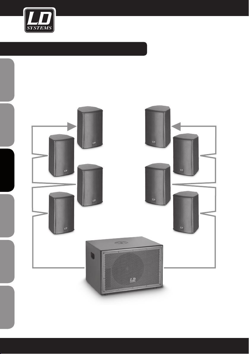
EXEMPLES DE coMBinAison :
1 X LDSUB10A + 2 X 4 LDSAT42G2(W)
ENGLISHDEUTSCHFRANCAIS
ESpAñoLpoLSKIITALIANo
FRANCAISFRANCAIS FRANCAISFRANCAIS
70
SPEAKER OUT LEFT SPEAKER OUT RIGHT

EXEMPLES DE coMBinAison :EXEMPLES DE coMBinAison :
1 X LDSUB10A + 2 X 2 LDSAT242G2(W)
FRANCAISFRANCAIS FRANCAISFRANCAIS
FRANCAISDEUTSCHENGLISH
SPEAKER OUT LEFT SPEAKER OUT RIGHT
ITALIANopoLSKIESpAñoL
71
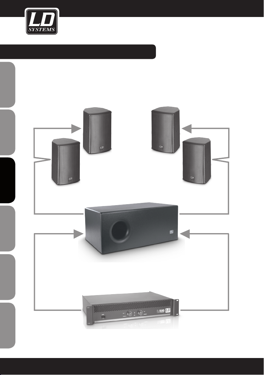
EXEMPLES DE coMBinAison :
1 X LDDJ500 + 1X LDSUB88 + 2 X 2 LDSAT62G2(W) )
ENGLISHDEUTSCHFRANCAIS
SAT OUT LEFT SAT OUT RIGHT
ESpAñoLpoLSKIITALIANo
FRANCAISFRANCAIS FRANCAISFRANCAIS
72
SUB88 IN LEFT SUB88 IN RIGHT
SPEAKER OUT LEFT SPEAKER OUT RIGHT

SUWMB10B (NOIR)
SUWMB10W (BLANC)
Fixation murale universelle pour enceinte, avec élingue de sécurité 4 articulations permettent d'orienter
l'enceinte dans pratiquement n'importe quelle position.
Charge maximale : 10 kg
FRANCAISFRANCAIS FRANCAISFRANCAIS
FRANCAISDEUTSCHENGLISH
ITALIANopoLSKIESpAñoL
73

CARACTÉRISTIQUES :
LDSAT42G2(W)
Type de produit Haut-Parleurs pour Installation
ENGLISHDEUTSCHFRANCAIS
ESpAñoLpoLSKIITALIANo
Type : passif
Diamètre boomers : 4"
Diamètre boomers : 101 mm
Aimant boomers : Ferrite
Marque boomers : fabrication sur cahier de charges
Diamètre tweeter : 1 "
Diamètre tweeter : 25 mm
Aimant tweeter : Ferrite
Marque tweeter : fabrication sur cahier de charges
Angle de dispersion (H x V) : 60 x 60 °
Puissance (eff.) : 60 W
Puissance admissible (crête) : 100 W
Réponse en fréquence : 75 Hz - 20.000 Hz
Efficacité (1 W/ 1 m) : 85 dB SPL
Niveau maximal de pression sonore : 103 dB SPL
Impédance nominale : 16 Ohms
Circuits de protection : Tweeter
Connecteurs d'entrée : 1
Type connecteur d'entrée : Bornier à pince
Matériau coffret : MDF, épaisseur 12 mm
Finition coffret : Laque de structure
Couleur coffret : noir (LDSAT42G2) / blanc (LDSAT42G2W)
Type de coffret : clos
Dimensions (L x H x P): 140 x 230 x 125 mm
Masse: 5 kg /paire
Divers : Livrée avec fixation murale
FRANCAISFRANCAIS FRANCAISFRANCAIS
74

CARACTÉRISTIQUES :
LDSAT242G2(W)
Type de produit : Enceinte pour Installation
Type : passif
Diamètre boomers : 2 x 4"
Diamètre boomers : 2 x 101 mm
Aimant boomers : Ferrite
Marque boomers : fabrication sur cahier de charges
Diamètre tweeter : 1"
Diamètre tweeter : 25 mm
Aimant tweeter : Ferrite
Marque tweeter : fabrication sur cahier de charges
Angle de dispersion (H x V) : 60 x 60 °
Puissance (eff.) : 100 W
Puissance admissible (crête) : 180 W
Réponse en fréquence : 75 Hz - 20.000 Hz
Efficacité : 88 dB SPL
Niveau maximal de pression sonore : 108 dB SPL
Impédance nominale : 8 Ohms
Fonctions de protection : Tweeter
Connecteurs d'entrée : 1
Type connecteur d'entrée : Bornier à pince
Matériau coffret : MDF, épaisseur 12 mm
Finition coffret : Laque de structure
Couleur coffret : noir (LDSAT242G2) / blanc (LDSAT242G2W)
Type de coffret : clos
Dimensions (L x H x P): 140 x 378 x 135 mm
Masse: 4,15 kg
Divers : Livrée avec fixation murale
FRANCAISFRANCAIS FRANCAISFRANCAIS
FRANCAISDEUTSCHENGLISH
75
ITALIANopoLSKIESpAñoL
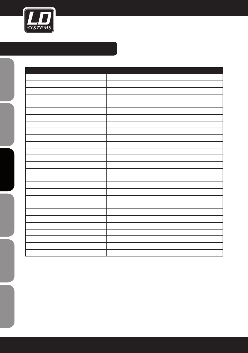
CARACTÉRISTIQUES :
LDSAT62G2(W)
Type de produit : Enceinte pour Installation
ENGLISHDEUTSCHFRANCAIS
ESpAñoLpoLSKIITALIANo
Type : passif
Diamètre boomer : 6,5 "
Diamètre boomer : 165 mm
Aimant boomer : Ferrite
Marque boomer : fabrication sur cahier de charges
Diamètre tweeter : 1 "
Diamètre tweeter : 25 mm
Aimant tweeter : Ferrite
Marque tweeter : fabrication sur cahier de charges
Angle de dispersion (H x V) : 60 x 60 °
Puissance (eff.) : 80 W
Puissance admissible (crête) : 130 W
Réponse en fréquence : 55 Hz - 20.000 Hz
Efficacité (1 W/ 1 m) : 89 dB SPL
Niveau maximal de pression sonore : 108 dB SPL
Impédance nominale : 16 Ohms
Fonctions de protection : Tweeter
Connecteurs d'entrée : 1
Type connecteur d'entrée : Bornier à pince
Matériau coffret : MDF, épaisseur 12 mm
Finition coffret : Laque de structure
Couleur coffret: noir (LDSAT62G2) / blanc (LDSAT62G2W)
Type de coffret : Bass reflex
Dimensions (L x H x P): 200 x 320 x 200 mm
Masse: 8,2 kg /paire
Divers : Livrée avec fixation murale
FRANCAISFRANCAIS FRANCAISFRANCAIS
76

CARACTÉRISTIQUES :
LDSAT82G2(W)
Type de produit : Enceinte pour Installation
Type : passif
Diamètre boomer : 8 "
Diamètre boomer : 203 mm
Aimant boomer : Ferrite
Marque boomer : fabrication sur cahier de charges
Diamètre tweeter : 1 "
Diamètre tweeter : 25 mm
Aimant tweeter : Ferrite
Marque tweeter : fabrication sur cahier de charges
Angle de dispersion (H x V) : 60 x 60 °
Puissance (eff.) : 120 W
Puissance admissible (crête) : 200 W
Réponse en fréquence : 50 Hz - 20.000 Hz
Efficacité (1 W/ 1 m) : 93 dB SPL
Niveau maximal de pression sonore : 114 dB SPL
Impédance nominale : 8 Ohms
Fonctions de protection : Tweeter
Connecteurs d'entrée : 1
Type connecteur d'entrée : Bornier à pince
Matériau coffret : MDF, épaisseur 15 mm
Finition coffret : Laque de structure
Couleur coffret : noir (LDSAT82G2) / blanc (LDSAT82G2W)
Type de coffret : Bass reflex
Dimensions (L x H x P): 274 x 410 x 243 mm
Poids: 7 kg
Divers : Livré avec fixation murale
FRANCAISFRANCAIS FRANCAISFRANCAIS
FRANCAISDEUTSCHENGLISH
77
ITALIANopoLSKIESpAñoL

CARACTÉRISTIQUES :
LDSUB88
Type de produit : Caisson de Basses pour Installation
ENGLISHDEUTSCHFRANCAIS
ESpAñoLpoLSKIITALIANo
Type : passif
Diamètre boomers : 2 x 8"
Diamètre boomers : 2 x 203 mm
Aimant boomers : Ferrite
Marque boomers : fabrication sur cahier de charges
Puissance (eff.) : 2 x 100 W
Puissance admissible (crête) : 2 x 180 W
Réponse en fréquence : 40 Hz - 120 Hz
Sensibilité (1 W/ 1 m) : 92 dB SPL
Niveau maximal de pression sonore : 115 dB SPL
Impédance nominale : 2 x 8 Ohms
Connecteurs d'entrée : 2
Type connecteur d'entrée : Bornier à pince
Sorties enceintes : 2
Connecteurs sorties enceintes : Bornier à pince
Matériau coffret : MDF, épaisseur 15 mm
Finition coffret : Laque de structure
Couleur coffret : noir
Type de coffret : Passe-bande
Dimensions (L x H x P): 600 x 250 x 350 mm
Masse: 13,3 kg
Divers : Filtre passe-bas intégré (fréquence de coupure 120 Hz)
FRANCAISFRANCAIS FRANCAISFRANCAIS
78
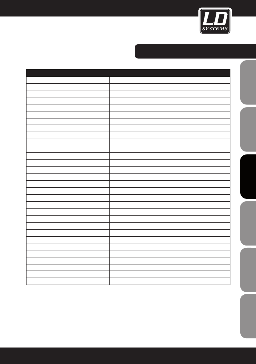
CARACTÉRISTIQUES :
LDSAT62AG2(W)
Type de produit : Haut-Parleurs pour Installation
Type : actif
Diamètre boomer : 6,5 "
Diamètre boomer : 165 mm
Aimant boomer : Ferrite
Marque boomer : fabrication sur cahier de charges
Diamètre tweeter : 1 "
Diamètre tweeter : 25 mm
Aimant tweeter : Ferrite
Marque tweeter : fabrication sur cahier de charges
Module amplificateur : Classe A/B
Angle de dispersion (H x V) : 60 x 60 °
Puissance (eff.) : 50 W
Réponse en fréquence : 55 Hz - 20.000 Hz
Niveau maximal de pression sonore : 108 dB SPL
Fonctions de protection : Tweeter, surcharge
Contrôles : Interrupteur On/Off, réglage de volume, sélecteur mode Auto
Indicateurs : LED POWER
Connecteurs entrées ligne : XLR/jack 6,35 mm (Combo)
Connecteur sortie ligne : XLR
Alimentation : Transformateur toroïdal
Tension d'alimentation : 220 V AC - 240 V AC, 50 - 60 Hz
Consommation (maxi) 80 VA
Matériau coffret : MDF, épaisseur 12 mm
Finition coffret : Laque de structure
Couleur coffret : noir (LDSAT62AG2) / blanc (LDSAT62AG2W)
Type de coffret : Bass reflex
Dimensions (L x H x P): 200 x 320 x 200 mm
Masse: 5,25 kg
Divers : Livrée avec fixation murale
FRANCAISFRANCAIS FRANCAISFRANCAIS
FRANCAISDEUTSCHENGLISH
79
ITALIANopoLSKIESpAñoL

CARACTÉRISTIQUES :
LDSUB88A
Type de produit : Caisson de Basses pour Installation
ENGLISHDEUTSCHFRANCAIS
ESpAñoLpoLSKIITALIANo
Type : actif
Diamètre boomers : 2 x 8"
Diamètre boomers : 2 x 203 mm
Aimant boomers : Ferrite
Marque boomers : fabrication sur cahier de charges
Module amplificateur : Classe A/B
Puissance (eff.) : 150 W
Réponse en fréquence : 40 Hz - 120 Hz
Efficacité (1 W/ 1 m) : 92 dB SPL
Niveau maximal de pression sonore : 115 dB SPL
Fonctions de protection : Surcharge
Contrôles : Inverseur de polarité (Phase 180°), potentiomètre réglage filtre
Indicateurs : Limit, Signal, Power
Entrées ligne : 1
Connecteurs entrées ligne : XLR/jack 6,35 mm (Combo)
Alimentation : Transformateur toroïdal
Tension d'alimentation : 220 V AC - 240 V AC, 50 - 60 Hz
Consommation (maxi) : 200 VA
Matériau coffret : MDF, épaisseur 15 mm
Finition coffret : Laque de structure
Couleur coffret : noir
Type de coffret : Passe-bande
Dimensions (L x H x P): 600 x 250 x 350 mm
Masse: 15 kg
passe-bas (réglable de 70 à 140 Hz)
FRANCAISFRANCAIS FRANCAISFRANCAIS
80

CARACTÉRISTIQUES :
LDSUB10A
Type de produit : Caissons de Basse Sono
Type : actif
Diamètre boomer : 10 "
Diamètre boomer : 254 mm
Aimant boomer : Ferrite
Marque boomer : fabrication sur cahier de charges
Diamètre bobine mobile boomer : 2 "
Diamètre bobine mobile boomer : 50,8 mm
Module amplificateur : Classe A/B
Puissance (eff.) : 3 x 120 W
Puissance admissible (crête) : 3 x 240 W
Réponse en fréquence caisson de basses : 40 Hz - 120 Hz
Niveau de pression sonore maximal (en
continu) :
Fonctions de protection : Surcharge, limiteur, court-circuit
Sensibilité d'entrée : 0,3 V eff.
Contrôles : Réglage de volume caisson, interrupteur (On/Off), réglage
Indicateurs : Power
Entrées ligne : 2
Connecteurs entrées ligne : Combo (mixte XLR/jack 6,35 mm)
Sorties ligne : 2 x Direct Out
Connecteurs sortie ligne : Entrée XLR
Sorties enceintes : 2
Connecteurs sorties enceintes : Borniers
Alimentation : Transformateur toroïdal
Tension d'alimentation : 220 V AC - 240 V AC, 50 - 60 Hz
Consommation (maxi) : 600 VA
Matériau coffret : MDF, épaisseur 15 mm
Finition coffret : Laque de structure
Type de coffret : Bass reflex
Dimensions (L x H x P): 505 x 345 x 425 mm
Masse: 21 kg
Divers : Embase filetée M20, poignées ergonomiques, sorties enceintes
118 dB SPL
volume général, inversion de polarité caisson
filtrées (filtre passe-haut de fréquence de coupure 170 Hz, pente
-18 dB/octave)
FRANCAISFRANCAIS FRANCAISFRANCAIS
FRANCAISDEUTSCHENGLISH
ITALIANopoLSKIESpAñoL
81

DECLARATIONS DecLArATions :
GARANTIE FABRICANT LIMITÉE
Cette garantie concerne tous les produits de marque Adam Hall, LD Systems, Defender, Palmer et Cameo.
Elle s‘applique également à tous les produits distribués par Adam Hall.
ENGLISHDEUTSCHFRANCAIS
Elle ne concerne pas les droits statutaires relatifs à la garantie envers le vendeur. En fait, elle justifie des requêtes
en garantie supplémentaires, indépendantes, envers Adam Hall.
Adam Hall garantit, pendant une période s‘étendant selon le cas de deux à cinq ans (à vérifier selon le produit) à
compter de la date d‘achat, que le produit Adam Hall que vous avez acheté directement auprès d‘Adam Hall ou
chez un revendeur autorisé est dépourvu de défaut, au niveau des composants ou de la fabrication, dans le cadre
d‘une utilisation normale.
La période pendant laquelle cette garantie limitée est applicable commence à partir de la date d‘achat. Cette date
se justifie d‘après une facture ou un bon de livraison daté. Dans le cas où des produits des marques citées ci
avant nécessiteraient une réparation pendant la période de garantie limitée, vous avez droit à des réparations sous
garantie, conformément aux termes et conditions exposés dans ce document.
Pendant toute la période de garantie limitée, Adam Hall réparera ou procédera au remplacement de tous les composants défectueux, ou le produit lui-même. En cas de réparation ou d‘échange pendant la période de garantie, les
pièces originales remplacées ou le produit échangé deviennent la propriété de la société Adam Hall.
Dans le cas improbable où votre produit Adam Hall serait sujet à des défaillances répétées, Adam Hall, à sa discrétion, peut choisir de mettre à votre disposition un appareil de remplacement de son choix, au moins équivalent à
votre produit de marque Adam Hall en termes de performances matérielles et techniques.
Adam Hall ne garantit pas que l‘utilisation de ce produit ne sera sujette à aucune interruption ni défaillance.
Adam Hall n‘est pas responsable des dommages occasionnés par le non-respect des instructions contenues dans
ESpAñoLpoLSKIITALIANo
le manuel d‘utilisation livré avec le produit de marque Adam Hall. La garantie fabricant ne s‘applique pas- aux
pièces d‘usure (accumulateurs par exemple) - aux produits dont le numéro de série a été effacé, ou qui ont été
endommagés ou rendus inutilisables à la suite d‘un accident - aux dommages provoqués une utilisation peu
précautionneuse, à une erreur de manipulation ou tout autre motif externe.
- en cas de dommages subis par des appareils suite à une utilisation hors des valeurs d‘usage des paramètres
(telles que mentionnées dans le manuel utilisateur livré avec le produit)
- en cas de dommages consécutifs à l‘utilisation de pièces de rechange non fabriquées ou non vendues par Adam
FRANCAISFRANCAIS FRANCAISFRANCAIS
Hall
- en cas de dommages consécutifs à des modifications ou réparations non assurées par Adam Hall
Ces termes et conditions constituent l‘accord de garantie complet et exclusif entre cous et Adam Hall, relativement
au produit de marque Adam Hall que vous avez acheté.
82
DECLARATIONS DecLArATions :
RESPONSABILITÉ LIMITÉE
Si votre appareil de marque Adam Hall présente, pendant la période de garantie, des défaillances au niveau des
composants ou de la fabrication, couvertes par les conditions ci avant, le seul recours, exclusif, est sa réparation
ou son remplacement au titre de cette garantie. Dans le cadre de cette garantie limitée, la responsabilité financière maximale d‘Adam Hall est expressément limitée à la plus faible des deux sommes suivantes : prix d‘achat
payé pour le produit ou coût de réparation ou de remplacement de tout composant matériel ne fonctionnant pas
correctement dans des conditions normales d‘utilisation.
Adam Hall ne peut être tenu pour financièrement responsable de tout dommage causé par le produit ou sa
défaillance – y compris toute perte de recettes ou de bénéfices, ni de tout dommage spécifique, incidentel ou
consécutif. De plus, Adam Hall n‘est pas responsable financièrement en cas de requête émanant d‘une tierce
partie ou de votre part pour le compte d‘une tierce partie.
Cette limitation de responsabilité financière s‘applique en cas de demande de dommages et intérêts ou de
poursuites, dans le cadre de cette garantie limitée ou en cas de procédure (négligence et stricte responsabilité
produit), de non-respect du contrat, ou de toute autre procédure. Cette limitation de responsabilité financière
ne peut être annulée ou amendée par quiconque. Cette limitation de responsabilité financière s‘applique même
si vous avez prévenu Adam Hall ou tout représentant autorisé de Adam Hall de la possibilité de tels dommages.
Toutefois, cette limitation de responsabilité financière ne s‘applique pas en cas de blessures aux personnes.
Cette garantie fabricant limitée vous donne des droits légaux spécifiques. Vous pouvez également avoir d‘autres
droits, variables d‘un état ou d‘un pays à l‘autre. Nous vous conseillons de vous reporter aux lois applicables
dans votre état ou votre pays afin de déterminer l‘étendue exacte de vos droits.
DEMANDE DE RÉPARATIONS SOUS GARANTIE
Pour demander des réparations sous garantie pour votre produit, veuillez contacter Adam Hall ou le revendeur
agréé Adam Hall auprès de qui vous l‘avez acheté.
FRANCAISFRANCAIS FRANCAISFRANCAIS
FRANCAISDEUTSCHENGLISH
DÉcLArATion De CONFORMITÉ CE
Les appareils commercialisés par Adam Hall répondent (à la date actuelle) aux exigences et spécifications applicables des Directives 1999/5/EC (R&TTE), 2004/108/EC (EMC) et 2006/95/EC (LVD). Pour plus d‘informations,
référez-vous au site www.adamhall.com.
ITALIANopoLSKIESpAñoL
83

DECLARATIONS DecLArATions :
MISE AU REBUT DE CE PRODUIT
(Applicable dans l‘Union Européenne et les autres pays européens dotés de systèmes de collecte sélective)
La présence de ce logo sur le produit ou son manuel d‘utilisation indique qu‘en fin de vie, il ne doit pas être
ENGLISHDEUTSCHFRANCAIS
jeté avec les autres déchets domestiques. Afin d‘éviter toute atteinte à l‘environnement ou à la santé humaine
pouvant résulter d‘une gestion incontrôlée des déchets, veuillez assurer son recyclage de manière responsable.
Séparez-le des autres types de déchets et recyclez-le, afin de promouvoir la réutilisation durable des ressources
naturelles.
Nous conseillons aux utilisateurs non professionnels de contacter le revendeur chez qui ils ont acheté le produit,
ou un représentant gouvernemental local, pour plus de détails sur le lieu de collecte et la façon de recycler cet
appareil dans le meilleur respect de l‘environnement possible..
Nous invitons les utilisateurs professionnels à contacter leur fournisseur et à vérifier les termes et conditions de
leur contrat d‘achat. Ce produit ne doit pas être mélangé à d‘autres déchets commerciaux lors de la collecte.
PROTECTION DE L'ENVIRONNEMENT eT ÉconoMies D'ÉnerGie
Économiser l'énergie constitue une contribution active efficace à la protection de l'environnement. Pensez à
éteindre tout appareil électrique dès que vous ne vous en servez plus. Pour éviter que les appareils placés en
mode de veille (Standby) ne continuent à consommer de l'électricité, débranchez-les de leur prise secteur.
ESpAñoLpoLSKIITALIANo
FRANCAISFRANCAIS FRANCAISFRANCAIS
Adam Hall GmbH, tous droits réservés. Les caractéristiques techniques et les fonctions disponibles sur le produit
sont sujettes à modifications. La photocopie, la traduction et toute forme de copie, partielle ou intégrale, de ce
manuel utilisateur sont interdites.
84

FRANCAISFRANCAIS FRANCAISFRANCAIS
FRANCAISDEUTSCHENGLISH
85
ITALIANopoLSKIESpAñoL

ENGLISHDEUTSCHFRANCAIS
¡Gracias por elegir LD-Systems!
Este equipo está diseñado y fabricado con los estándares de calidad más exigentes, para garantizar un correcto
funcionamiento durante muchos años. Los productos de LD-Systems se caracterizan por su gran calidad, avalada por el prestigio de la marca y una dilatada experiencia como fabricante.
Lea atentamente este manual de usuario para poder aprovechar rápidamente toda la funcionalidad de su nuevo
producto de LD Systems.
Si desea obtener información sobre LD-SYSTEMS, visite nuestro sitio web WWW.LD-SYSTEMS.COM
Introducción
La serie SATG² de LD Systems consta de altavoces compactos, ideales para pequeñas instalaciones, que se
integran discretamente en cualquier entorno, como en restaurantes, tiendas y también en el hogar.
ESpAñoLpoLSKIITALIANo
Incluye cuatro altavoces pasivos de 2vías de diferentes tamaños y un altavoz activo, disponibles en negro o
blanco. La serie se completa con un subwoofer pasivo y dos subwoofers activos.
FRANCAISFRANCAIS FRANCAISFRANCAIS
86

LD series SATG²/SUB
ALTAVOCES PASIVOS DE INSTALACIÓN: LDsAT42G2(W) / LDsAT242G2(W) /
LDsAT62G2(W) / LDsAT82G2(W) / LDsUB88
ALTAVOCES ACTIVOS DE INSTALACIÓN: LDsAT62AG2(W) / LDsUB88A /
LDsUB10A
FRANCAISFRANCAIS FRANCAISFRANCAIS
FRANCAISDEUTSCHENGLISH
ITALIANOPOLSKIESPAÑOL
87

MEDIDAS De seGUriDAD:
1. Lea atentamente las instrucciones de este manual.
2. Guarde toda la información en un lugar seguro para futuras consultas.
3. Siga las instrucciones indicadas.
4. Siga todas las advertencias. No quite las instrucciones de seguridad ni cualquier otra información indicada en el equipo.
5. Utilice el equipo únicamente según la finalidad prevista.
ENGLISHDEUTSCHFRANCAIS
6. Utilice solo soportes y fijaciones que sean robustos y adecuados cuando instale el equipo en instalaciones
fijas. Asegúrese de que los soportes de pared están correctamente instalados y firmemente fijados. Asegúrese de
que el equipo está sólidamente instalado y no se puede caer.
7. Al instalar el equipo, respete las normas de seguridad aplicables en su país.
8. Evite instalar el equipo cerca de radiadores, acumuladores de calor, estufas o cualquier otra fuente de calor. Asegúrese de que el equipo esté instalado en un lugar con ventilación suficiente para evitar cualquier sobrecalentamiento.
9. No coloque sobre el equipo fuentes de llamas sin protección, por ejemplo, velas encendidas.
10. Evite bloquear las rejillas de ventilación.
11. No utilice este equipo cerca del agua (excepto los equipos específicamente diseñados para uso en exterior,
en cuyo caso tenga en cuenta las indicaciones mencionadas a continuación). No exponga este equipo a materiales, líquidos o gases inflamables.
12. Evite exponer el equipo a gotas o salpicaduras que puedan caer dentro del mismo. No coloque recipientes
llenos de líquido, como floreros o vasos, sobre el equipo.
13. Asegúrese de no dejar caer ningún objeto dentro del equipo.
14. Emplee el equipo únicamente con los accesorios recomendados por el fabricante.
15. No abra el equipo ni intente modificarlo.
16. Una vez conectado el equipo, compruebe que en toda la longitud del cableado no hay peligro de que provoque una caída, por ejemplo.
17. Durante el transporte, asegúrese de que el equipo no se caiga y pueda causar daños personales o materiales.
18. Si el equipo no funciona correctamente, o si se ha vertido líquido sobre él, o si un objeto ha caído en su
interior o si ha sufrido algún desperfecto, apague inmediatamente el equipo y desenchufe el cable eléctrico (si se
trata de un equipo activo). Únicamente un técnico especialista debe reparar el equipo.
19. Para limpiar el equipo utilice un paño seco.
ESpAñoLpoLSKIITALIANo
20. Procure seguir las normas vigentes en su país sobre reciclaje de desechos. Separe los componentes de
plástico, papel y cartón del paquete para reciclarlos en sus contenedores respectivos.
21. No deje las bolsas de plástico al alcance de los niños.
PARA LOS EQUIPOS CON TOMA ELÉCTRICA:
22. ADVERTENCIA: Si el cable eléctrico está provisto de un contacto de protección, debe conectarse a una toma
eléctrica con conexión a tierra. No desactivar nunca esta conexión de protección a tierra del cable eléctrico.
FRANCAISFRANCAIS FRANCAISFRANCAIS
23. Si el equipo ha estado expuesto a un cambio brusco de temperatura (por ejemplo, después del transporte),
no lo encienda inmediatamente. La condensación o la humedad podrían dañar el equipo. Deje que el equipo
alcance la temperatura ambiente antes de encenderlo.
24. Antes de conectar el cable eléctrico a la toma de corriente, compruebe si la tensión y la frecuencia del
suministro eléctrico coinciden con las especificaciones de este equipo. Si el equipo dispone de un selector de
tensión, antes de enchufarlo a la red eléctrica, asegúrese de que el valor seleccionado coincide con la tensión de
suministro. Si el enchufe o el adaptador de corriente no encajan en la toma eléctrica, consulte a un electricista.
25. Asegúrese de que el cable eléctrico no está pinzado. Evite que el cable resulte pellizcado, sobre todo en los
extremos de conexión al equipo y en la toma eléctrica.
26. Al conectar el equipo, asegúrese de que el cable eléctrico o el adaptador de corriente estén siempre
accesibles. Desconecte el equipo de la toma de corriente cuando no esté en uso o antes de limpiarlo. Para ello,
88
SEGURIDAD:
desconecte el cable eléctrico y el adaptador de corriente del conector del equipo en vez de desenchufar el cable
de la toma eléctrica. No tocar el cable eléctrico ni el adaptador de corriente con las manos húmedas.
27. No encienda y apague el equipo en cortos intervalos de tiempo, ya que se reduce así la vida útil del sistema.
28. NOTA IMPORTANTE: Sustituya los fusibles únicamente por otros del mismo tipo y de las mismas características. Si el fusible se funde continuamente, póngase en contacto con un servicio técnico autorizado.
29. Para desconectar completamente el equipo de la tensión eléctrica, desenchufe el cable eléctrico o el adaptador de corriente de la toma eléctrica.
30. Si el equipo dispone de un enchufe eléctrico Volex, deberá desbloquearse el Volex del equipo para desenchufarlo. Esto implica que un tirón en el cable eléctrico puede desplazar el equipo y provocar daños personales o
materiales. Por tanto, asegúrese de instalar los cables con sumo cuidado.
31. Si es probable que caiga un rayo por una tormenta eléctrica o si no va a emplear el equipo durante mucho
tiempo, desenchufe el cable eléctrico y el adaptador de corriente.
CAUTION
RISK OF ELECTRIC SHOCK
DO NOT OPEN
ADVERTENCIA:
Para evitar el riesgo de descarga eléctrica, no retire la tapa. El equipo no contiene piezas que el usuario pueda
reparar o sustituir. Para cualquier tarea de mantenimiento o reparación, acuda a un técnico cualificado.
El símbolo de rayo dentro de un triángulo equilátero advierte al usuario de la presencia de tensiones
peligrosas sin aislamiento dentro del equipo que pueden causar una descarga eléctrica y suponer un
riesgo para la salud.
El símbolo de exclamación dentro de un triángulo equilátero advierte al usuario de la existencia de
importantes instrucciones de uso y mantenimiento.
ADVERTENCIA: ¡ALTO VOLUMEN!
Este equipo se destina a un uso profesional. Por consiguiente, si se aplica a un uso comercial, estará sujeto a
las normas y reglamentos de la Asociación para la prevención de accidentes de su sector profesional. Como
fabricante, Adam Hall tiene la obligación de informar formalmente a los usuarios de la existencia de posibles
riesgos para la salud.
Daños auditivos por exposición prolongada a un nivel SPL alto: este equipo puede generar fácilmente un nivel de
presión sonora (SPL) lo suficientemente elevado como para causar daños auditivos permanentes a los artistas, el
personal de producción y el público. Deben tomarse precauciones para evitar la exposición prolongada a un SPL
de más de 90 dB.
ENGLISH
FRANCAISFRANCAIS FRANCAISFRANCAIS
FRANCAISDEUTSCHENGLISH
¡ATENCIÓN! INFORMACIÓN IMPORTANTE SOBRE LOS PRODUCTOS DE ILUMINACIÓN
1. No mire el haz de luz desde una distancia inferior a 40 cm.
2. No mire el haz de luz de cerca durante periodos prolongados.
3. No mire directamente el haz de luz con instrumentos ópticos, como lentes de aumento.
4. ¡Los efectos estroboscópicos pueden a veces causar convulsiones en personas fotosensibles! Las personas
con epilepsia deben evitar los lugares en los que se usan luces estroboscópicas.
ITALIANOPOLSKIESPAÑOL
89

INSTRUCCIONES DE USO:
ALTAVOZ PASIVO
SAT42G2(W) y SAT62G2(W)
Se puede conectar en paralelo hasta cuatro altavoces SAT42G2(W) o SAT62G2(W) a cada salida de amplificador,
ENGLISHDEUTSCHFRANCAIS
obteniendo una impedancia equivalente de 4ohmios. La conexión en paralelo al siguiente altavoz se realiza
fácilmente mediante los conectores situados en el panel posterior.
SAT242G2(W) y SAT82G2(W)
Se puede conectar en paralelo hasta dos altavoces SAT242G2(W) o SAT82G2(W) a cada salida de amplificador,
obteniendo una impedancia equivalente de 4ohmios. La conexión en paralelo al siguiente altavoz se realiza
fácilmente mediante los conectores situados en el panel posterior.
Conexión del SUB88 a SAT42G2(W), SAT62G2(W), SAT242G2(W) o SAT82G2(W)
Conecte los cables de altavoz de las salidas izquierda y derecha del amplificador en los terminales de entrada
LEFT y RIGHT del panel posterior del subwoofer.
A continuación, conecte los altavoces de la serie SAT a los terminales de salida LEFT y RIGHT del subwoofer.
De este modo, se puede conectar en paralelo hasta dos altavoces SAT42G2(W) o SAT62G2(W) a cada salida del
subwoofer (LEFT y RIGHT), obteniendo una impedancia equivalente de 4ohmios.
De este modo, se puede conectar en paralelo un altavoz SAT242G2(W) o SAT82G2(W) a cada salida del
subwoofer (LEFT y RIGHT), obteniendo una impedancia equivalente de 4ohmios.
Se recomienda emplear cables de altavoz con una sección de 2x1,5mm² como mínimo.
ALTAVOZ ACTIVO
Se recomienda encender el altavoz activo el último y apagarlo el primero, para así
evitar los chasquidos que se producen al encender una mesa de mezclas, por ejemplo. Si hay varios altavoces activos
(SAT62AG2) conectados en cadena, enciéndalos en orden secuencial, del primero al último, y apáguelos en
ESpAñoLpoLSKIITALIANo
orden inverso, del último al primero.
Antes de enchufar el altavoz activo, asegúrese de que está apagado. La conexión puede realizarse mediante un
jack de 6,3mm
(balanceado de tres pines/no balanceado de dos pines) o un XLR de tres pines balanceado
. Después de haber conectado todos los cables necesarios y ajustado al mínimo el volumen (MAIN LEVEL) del
altavoz activo, puede encender la fuente de audio (por ejemplo, una mesa de mezclas). Ahora ya puede encender
FRANCAISFRANCAIS FRANCAISFRANCAIS
el altavoz activo. Dé paso a la señal de audio y gire el potenciómetro MAIN LEVEL hacia la derecha hasta
alcanzar el volumen deseado. Siga este procedimiento con todos los altavoces activos conectados.
Los distintos conectores, controles e indicadores se describen en las siguientes páginas de este manual.
90
INSTRUCCIONES DE USO:
Conexión del SUB10A a altavoces pasivos de la serie SAT
Conecte los altavoces pasivos de la serie SAT a las salidas de altavoz (SPEAKER OUT LEFT y RIGHT) del SUB10A.
Se puede conectar en paralelo hasta cuatro altavoces SAT42G2(W) o SAT62G2(W) a cada salida de altavoz.
La conexión en paralelo al siguiente altavoz se realiza fácilmente mediante los conectores situados en el panel
posterior.
Se puede conectar en paralelo hasta dos altavoces SAT242G2(W) o SAT82G2(W) a cada salida de altavoz.
La conexión en paralelo al siguiente altavoz se realiza fácilmente mediante los conectores situados en el panel
posterior.
Se recomienda emplear cables de altavoz con una sección de 2x1,5mm² como mínimo.
Conexión del SUB10A a altavoces activos SAT62AG2(W)
Conecte los altavoces activos a las salidas de línea (LINE DIRECT OUTPUT) del SUB10A.
CONEXIÓN EN BUCLE DE LA SEÑAL
Los altavoces activos SAT62AG2(W) permiten enviar en bucle su señal de audio a otros equipos adicionales,
mediante un cable XLR de tres pines
. Por lo tanto, no es necesario conectar estos equipos adicionales a la fuente de audio. Compruebe
que los cables XLR utilizados sean de alta calidad y que estén correctamente tendidos.
SUB88A
Para conectar el subwoofer SUB88A a los altavoces activos SAT62AG2, el subwoofer debe ser el último equipo
de la cadena de sonido, ya que dispone sólo de una entrada de línea.
FRANCAISFRANCAIS FRANCAISFRANCAIS
FRANCAISDEUTSCHENGLISH
ITALIANOPOLSKIESPAÑOL
91
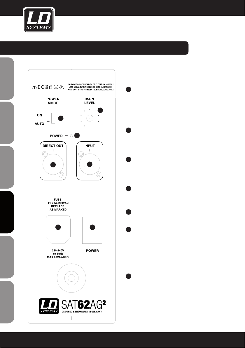
CONEXIONES, conTroLes e inDicADores:
LDSAT62AG2(W):
(LDSAT62AG2 en la figura)
ENGLISHDEUTSCHFRANCAIS
ESpAñoLpoLSKIITALIANo
FRANCAISFRANCAIS FRANCAISFRANCAIS
5
6
7
4
3
21
1
TOMA ELÉCTRICA
Toma IEC 220-240V con portafusibles integrado.
NOTA IMPORTANTE: Sustituya el fusible únicamente
por otro del mismo tipo y características. Si el
fusible se fundiera continuamente, póngase en
contacto con un servicio técnico autorizado.
2
POWER
Interruptor de encendido/apagado. Antes de encender o apagar, ponga el volumen a cero (MAIN LEVEL
completamente girado a la izquierda).
3
ENTRADA DE LÍNEA BALANCEADA
Entrada de línea balanceada (combo XLR/jack de
6,3mm) para la conexión de equipos, como un
mezclador).
4
DIRECT OUT
Salida de línea balanceada XLR para la conexión
en bucle de la señal.
5
MAIN LEVEL
Control de volumen.
6
POWER MODE
Conmuta entre el funcionamiento continuo (ON)
y el modo automático (AUTO). En la posición
AUTO, el amplificador del altavoz se enciende
en cuanto recibe una señal de audio. Al cabo de
varios minutos sin señal, el amplificador vuelve
automáticamente al modo de espera.
92
7
LED POWER
El LED se ilumina de color rojo si el equipo está
encendido y también si funciona en modo AUTO
sin señal a la entrada. Si hay señal a la entrada, el
LED pasará a iluminarse de color verde.
El LED también se ilumina de color verde si el
equipo está encendido (ON).

CONEXIONES, conTroLes e inDicADores:
1
2
3
4 4
5 5
7
6
8
LDSUB10A:
1
MAIN LEVEL
Volumen general del sistema (subwoofer y altavoces
pasivos conectados).
2
SUB PHASE
Conmutador de fase para el subwoofer (0°/180°).
3
SUB LEVEL
Permite ajustar el volumen del subwoofer respecto
al de los satélites.
4
LINE DIRECT OUTPUT (LEFT / RIGHT)
Salida de línea balanceada XLR (izquierda y
derecha) para la conexión en bucle de la señal.
5
LINE INPUT (LEFT / RIGHT)
Entrada de línea balanceada (combo XLR/jack de
6,3mm, izquierda y derecha) para la conexión de
equipos, como un mezclador).
6
SPEAKER OUT (LEFT / RIGHT)
Bornas de conexión para el cable de altavoz. Conexión
para altavoces o sistemas de altavoces de impedancia
total por canal de 4ohmios, como mínimo.
Conecte el conductor positivo (+) del cable de
altavoz al borne rojo (+), y el conductor negativo (-)
del cable de altavoz al borne negro (-) del canal correspondiente. Opcionalmente, también puede emplear cables de altavoz con conectores de banana.
7
TOMA ELÉCTRICA
Toma IEC 220-240V con portafusibles integrado.
NOTA IMPORTANTE: Sustituya el fusible únicamente
por otro del mismo tipo y características. Si el
fusible se fundiera continuamente, póngase en
contacto con un servicio técnico autorizado.
8
POWER
Interruptor de encendido/apagado. Antes de encender
o apagar, ponga el volumen a cero (MAIN LEVEL
completamente girado a la izquierda).
FRANCAISFRANCAIS FRANCAISFRANCAIS
FRANCAISDEUTSCHENGLISH
ITALIANOPOLSKIESPAÑOL
93

CONEXIONES, conTroLes e inDicADores:
ENGLISHDEUTSCHFRANCAIS
4
5
9
8
7
ESpAñoLpoLSKIITALIANo
FRANCAISFRANCAIS FRANCAISFRANCAIS
6
2
1
3
94

CONEXIONES, conTroLes e inDicADores:
LDSUB88A:
1
TOMA ELÉCTRICA
Toma IEC 220-240V con portafusibles integrado.
NOTA IMPORTANTE: Sustituya el fusible únicamente por otro del mismo tipo y características. Si el fusible se
fundiera continuamente, póngase en contacto con un servicio técnico autorizado.
2
POWER
Interruptor de encendido/apagado. Antes de encender o apagar, ponga el volumen a cero (SUB LEVEL
completamente girado a la izquierda).
3
ENTRADA DE LÍNEA BALANCEADA
Entrada de línea balanceada (combo XLR/jack de 6,3mm) para la conexión de equipos, como un mezclador).
4
SUB LEVEL
Control de volumen.
5
SUB CROSSOVER
Filtro paso bajos, variable de 70 a 140Hz. Permite ajustar la frecuencia de corte del subwoofer.
6
SUB PHASE
Conmutador de fase para el subwoofer (0°/180°).
7
LED POWER
Se ilumina cuando el subwoofer está encendido y enchufado correctamente a la red eléctrica.
FRANCAISFRANCAIS FRANCAISFRANCAIS
FRANCAISDEUTSCHENGLISH
8
LED SIGNAL
Se ilumina cuando en la entrada de línea se tiene una señal de audio.
9
LED LIMIT
Se ilumina cuando el altavoz se lleva al límite. No es crítico si el LED parpadea brevemente, ya que el limitador
interno regulará la saturación. En cambio, si el LED permanece encendido, reduzca el nivel de entrada.
ITALIANOPOLSKIESPAÑOL
95

CONEXIONES, conTroLes e inDicADores:
ALTAVOZ PASIVO LDSATG2:
(LDSAT42G2W en la figura)
ENGLISHDEUTSCHFRANCAIS
ESpAñoLpoLSKIITALIANo
BORNAS DE CONEXIÓN PARA EL CABLE DE
ALTAVOZ
Conecte el conductor positivo (+) del cable de
altavoz procedente del amplificador al borne rojo (+),
y el conductor negativo (-) del cable de altavoz al
borne negro (-).
SUBWOOFER PASIVO LDSUB88:
SUB88 IN (en la figura IN LEFT)
Bornas de conexión para el cable de altavoz.
Conecte el conductor positivo (OUTPUT LEFT +) del
cable de altavoz procedente del amplificador al borne
rojo (IN LEFT +), y el conductor negativo (OUTPUT
LEFT -) del cable de altavoz al borne negro (IN LEFT -)
del subwoofer.
De igual forma, conecte IN RIGHT del SUB88 y OUTPUT RIGHT del amplificador.
FRANCAISFRANCAIS FRANCAISFRANCAIS
96
SUB88 SAT OUT (en la figura SAT OUT LEFT)
Bornas de conexión para el cable de altavoz.
Conecte el conductor positivo (+) del cable de altavoz
al borne rojo (SAT OUT LEFT +), y el conductor
negativo (-) del cable de altavoz al borne negro (SAT
OUT LEFT -).
De igual forma, conecte los altavoces de la serie
SATG2 mediante cables de altavoz.
IMPORTANTE: Tenga en cuenta las notas sobre el
subwoofer LDSUB88 y los altavoces pasivos de la
serie LDSATG2 en la sección "INSTRUCCIONES DE
USO" de este manual.

SOPORTE DE ALTAVOZ sUMinisTrADo:CONEXIONES, conTroLes e inDicADores:
1
3
1
SOPORTE DE PARED
2
TORNILLO M6
3
SOPORTE EN U
4
ARANDELA
2
5
4
FRANCAISFRANCAIS FRANCAISFRANCAIS
FRANCAISDEUTSCHENGLISH
6
8
7
9
6
ARANDELA DE GOMA
7
TORNILLO ALLEN M6 x 16
8
ARANDELA ELÁSTICA
9
ARANDELA
5
PALOMILLA M6
NOTA: los soportes de altavoz para montaje en pared se suministran con todos los altavoces de la serie SATG2.
En los altavoces LDSAT242G2(W), además del soporte para montaje vertical se suministra también el soporte de
montaje horizontal.
ITALIANOPOLSKIESPAÑOL
97

EJEMPLO DEcoMBinAciones:
1 X LDSUB10A + 2 X 4 LDSAT42G2(W)
ENGLISHDEUTSCHFRANCAIS
ESpAñoLpoLSKIITALIANo
FRANCAISFRANCAIS FRANCAISFRANCAIS
98
SPEAKER OUT LEFT SPEAKER OUT RIGHT
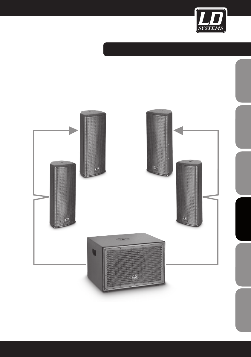
EJEMPLO DEcoMBinAciones:EJEMPLO DEcoMBinAciones:
1 X LDSUB10A + 2 X 2 LDSAT242G2(W)
FRANCAISFRANCAIS FRANCAISFRANCAIS
FRANCAISDEUTSCHENGLISH
SPEAKER OUT LEFT SPEAKER OUT RIGHT
ITALIANOPOLSKIESPAÑOL
99

EJEMPLO DEcoMBinAciones:
1 X LDDJ500 + 1X LDSUB88 + 2 X 2 LDSAT62G2(W) )
ENGLISHDEUTSCHFRANCAIS
SAT OUT LEFT SAT OUT RIGHT
ESpAñoLpoLSKIITALIANo
FRANCAISFRANCAIS FRANCAISFRANCAIS
100
SUB88 IN LEFT SUB88 IN RIGHT
SPEAKER OUT LEFT SPEAKER OUT RIGHT
 Loading...