


LEC-2220
Table of contents
 Loading...
>>
Embedded &
Industrial Computing
Hardware Platforms for Embedded and Industrial Computing
LEC-2220
Preliminary
User's Manual
Publication date:2011-10-03
2
About
About
Embedded and Industrial Computing
Overview
Icon Descriptions
The icons are used in the manual to serve as an indication
of interest topics or important messages. Below is a
description of these icons:
NOTE: This check mark indicates that
there is a note of interest and is something
that you should pay special attention to
while using the product.
WARNING: This exclamation point
indicates that there is a caution or
warning and it is something that could
damage your property or product.
Online Resources
The listed websites are links to the on-line product
information and technical support.
Resource Website
Lanner http://www.lannerinc.com
Product Resources http://assist.lannerinc.com
RMA http://eRMA.lannerinc.com
Copyright and Trademarks
This document is copyrighted, © 2011. All rights are
reserved. The original manufacturer reserves the right to
make improvements to the products described in this
manual at any time without notice.
No part of this manual may be reproduced, copied,
translated or transmitted in any form or by any means
without the prior written permission of the original
manufacturer. Information provided in this manual is
intended to be accurate and reliable. However, the original
manufacturer assumes no responsibility for its use, nor for
any infringements upon the rights of third parties that
may result from such use.
Acknowledgement
Intel, Pentium and Celeron are registered trademarks of
Intel Corp.
Microsoft Windows and MS-DOS are registered trademarks
of Microsoft Corp.
All other product names or trademarks are properties of
their respective owners.
Compliances and Certification
CE Certication
This product has passed the CE test for environmental
specifications. Test conditions for passing included the
equipment being operated within an industrial enclosure.
In order to protect the product from being damaged by
ESD (Electrostatic Discharge) and EMI leakage, we strongly
recommend the use of CE-compliant industrial enclosure
products.
FCC Class A Certication
This equipment has been tested and found to comply
with the limits for a Class A digital device, pursuant to Part
15 of the FCC Rules. These limits are designed to provide
reasonable protection against harmful interference when
the equipment is operated in a commercial environment.
This equipment generates, uses and can radiate radio
frequency energy and, if not installed and used in
accordance with the instruction manual, may cause
harmful interference to radio communications. Operation
of this equipment in a residential area is likely to cause
harmful interference in which case the user will be required
to correct the interference at his own expense.

TTaTTable of Contentsbeable of Contents
3
Chapter 1: Introduction 4
System Specication . . . . . . . . . . . . . . . . . . . . . . . . . . . . . . . . . . . . . . . . . . . 4
Package Contents . . . . . . . . . . . . . . . . . . . . . . . . . . . . . . . . . . . . . . . . . . . . . 5
Optional Accessories . . . . . . . . . . . . . . . . . . . . . . . . . . . . . . . . . . . . . . . . . . . 5
Chapter 2: System Components 6
System Drawing . . . . . . . . . . . . . . . . . . . . . . . . . . . . . . . . . . . . . . . . . . . . . . 6
System Drawing (Continued) . . . . . . . . . . . . . . . . . . . . . . . . . . . . . . . . . . . . . . 7
Block Diagram . . . . . . . . . . . . . . . . . . . . . . . . . . . . . . . . . . . . . . . . . . . . . . . 8
Front Components. . . . . . . . . . . . . . . . . . . . . . . . . . . . . . . . . . . . . . . . . . . . . 9
Rear Components . . . . . . . . . . . . . . . . . . . . . . . . . . . . . . . . . . . . . . . . . . . . .10
Chapter 3: Board Layout 11
External Connectors. . . . . . . . . . . . . . . . . . . . . . . . . . . . . . . . . . . . . . . . . . . .11
Internal Connectors and Jumpers . . . . . . . . . . . . . . . . . . . . . . . . . . . . . . . . . . .12
Internal Connectors and Jumpers (backside) . . . . . . . . . . . . . . . . . . . . . . . . . . . .13
Connectors and Jumpers List. . . . . . . . . . . . . . . . . . . . . . . . . . . . . . . . . . . . . .14
Jumper Settings . . . . . . . . . . . . . . . . . . . . . . . . . . . . . . . . . . . . . . . . . . . . . .15
Chapter 4: Hardware Setup 20
Preparing the Hardware Installation. . . . . . . . . . . . . . . . . . . . . . . . . . . . . . . . . .20
Installing the System Memory . . . . . . . . . . . . . . . . . . . . . . . . . . . . . . . . . . . . .20
Installing the CPU . . . . . . . . . . . . . . . . . . . . . . . . . . . . . . . . . . . . . . . . . . . . .20
Wireless Module Installation . . . . . . . . . . . . . . . . . . . . . . . . . . . . . . . . . . . . . .21
3G SIM Card Installation . . . . . . . . . . . . . . . . . . . . . . . . . . . . . . . . . . . . . . . . .21
PCI/PCIe Riser Card Installation . . . . . . . . . . . . . . . . . . . . . . . . . . . . . . . . . . . . .22
On 2220P with one PCIe slot. . . . . . . . . . . . . . . . . . . . . . . . . . . . . . . . . . . .22
Installing the Hard Disk . . . . . . . . . . . . . . . . . . . . . . . . . . . . . . . . . . . . . . . . . .22
On 2220P2 with 2 PCI slot . . . . . . . . . . . . . . . . . . . . . . . . . . . . . . . . . . . . .23
Connecting Power . . . . . . . . . . . . . . . . . . . . . . . . . . . . . . . . . . . . . . . . . . . . .23
Wall Mounting . . . . . . . . . . . . . . . . . . . . . . . . . . . . . . . . . . . . . . . . . . . . . . .23
Appendix A: Programming Watchdog Timer 24
Appendix B:
Digital Input/Output Control on the GPIO port 29
Appendix G:
Terms and Conditions 31
Warranty Policy . . . . . . . . . . . . . . . . . . . . . . . . . . . . . . . . . . . . . . . . . . . .31
RMA Service . . . . . . . . . . . . . . . . . . . . . . . . . . . . . . . . . . . . . . . . . . . . . .31

4
Introduction
Chapter 1
Embedded and Industrial Computing
Chapter 1:
Introduction
Thank you for choosing the LEC-2220. The LEC-2220
features Intel i5/i7 and Celeron processors. It has dual LAN
as well as DVI-I and DVI-D connectors for high demand of
Internet and video playback applications. The LEC-2220
also offers a variety of different expansion opportunities to
further customize the platform. Two different expansion
are possible:
On model LEC-2220P, it comes with one PCIe or one PCI
slot.
On model LEC-2220P2, it comes with 2 PCI slots.
These expansions adds capabilities of video capture or
extended LAN connections.
The following highlight the capabilities of the LEC-2220
system:
Intel HD Graphics Engine •
DVI-I and DVI-D video out •
Dual 10/100/1000 Mbps LAN •
USB x 6, COM x 6, and DIDO x 1 •
SATA HDD support •
Power-on switch through the Phoenix connector for •
distant control
Totally 6 serial ports supporting Hardware Auto flow •
Control: DB9 x2 for RS232/422/485 x1 and RS232 x1,
10-pin Terminal Block for RS232 x3 and RS232/422/485
x1;
Audio input and output through Mic-in and Line-out •
jack
Aluminum extrusion enclosure which helps heat •
dissipation
Smart FAN which can be controlled to operate when •
reaching the target CPU temperature
System Specification
LEC 2 Series
LEC-2220
Dimension (WxHxD)
277x(67/89)x194mm
10.91”x(2.64/3.50)”x7.64”
Processor
Intel i7/i5/Celeron
Chipset
HM55
System
Technology DDR3 SODIMM x2
Memory
Max. Capacity Up to 8GB
Storage
IDE N/A
SATA 2.5” HDD/SSD drive bay x1
Ethernet Controller
Intel 82574L x2
Graphic Controller
Intel HD Graphics
Audio Controller
Realtek ALC888S
IO
LAN GbE RJ45 x2
Display DVI-I x1 DVI-D x1
Video Grabber No
Audio
Phone Jack x2 for Mic-in and
Line-out
Serial I/O
Totally 6: DB9 x2 for
RS232/422/485 x1 and RS232
x1, 10-pin Terminal Block for
RS232 x3 and RS232/422/485
x1
GPS No
Digital I/O
DB9 Female x1 for DI x4 & DO
x4 (5V TTL)
USB 2.0
Type A x4
Internal x2
Power Input 2-pin terminal block
Expansion
Mini-PCIex1 with SIM card
reader ; LEC-2220P: PCI x1 or
PCIe x1 ; LEC-2220P2: PCI x2
Others
External: Power-on button,
Power-on switch, reset.
Internal: PS/2 keyboard and
mouse, +5Vdc output
Power Input
+9~30Vdc, ATX Mode
AC Adapter
75W +19V @ 3.95A
Hardware Monitor
Fintek F81865 integrated watch-
dog timer 1~255 level
OS Support
Linux , XPE/WES2009, XP PRO
FES, WS7E, WS7P, WIN 7 PRO-E

5
Introduction
Chapter 1
Embedded and Industrial Computing
Package Contents
Your package contains the following items:
LEC-2220 Fanless Embedded System •
Serial-ATA/Power Cable (P/N: 080W1N0002001) •
Wall-Mounting Kit (P/N: SE9ESA900R100) •
Drivers and User’s Manual CD (P/N: S09OADA09H100 ) •
2-pin Female Terminal Block (P/N: 04AW20023Z101) •
10-pin Female Terminal Block (P/N: 04AW20101O101) •
Optional Accessories
The system has a variety of optional accessories including
the power cords and Wi-Fi or 3G modules for extended
capabilities. For details of these modules, visit:
http://www.lannerinc.com/Embedded_Computing/LEC-
2220
Certications
CE, FCC Class A
Compliance
No
Operating Temperature Range
with Industrial Components
(Industrial Memory, CF, HDD,
SSD….)
-20~55°C/-4~131°F
Operating Temperature Range
with Commercial Components
-5~45°C/23~113°F
Extended Operating Temperature
Tested: 70°C: No Damage after 72-
hours full-loading operating -40°C:
Bootable after 24-hours
Yes

6
System Components
Chapter 2
Embedded and Industrial Computing
Chapter 2:
System Components
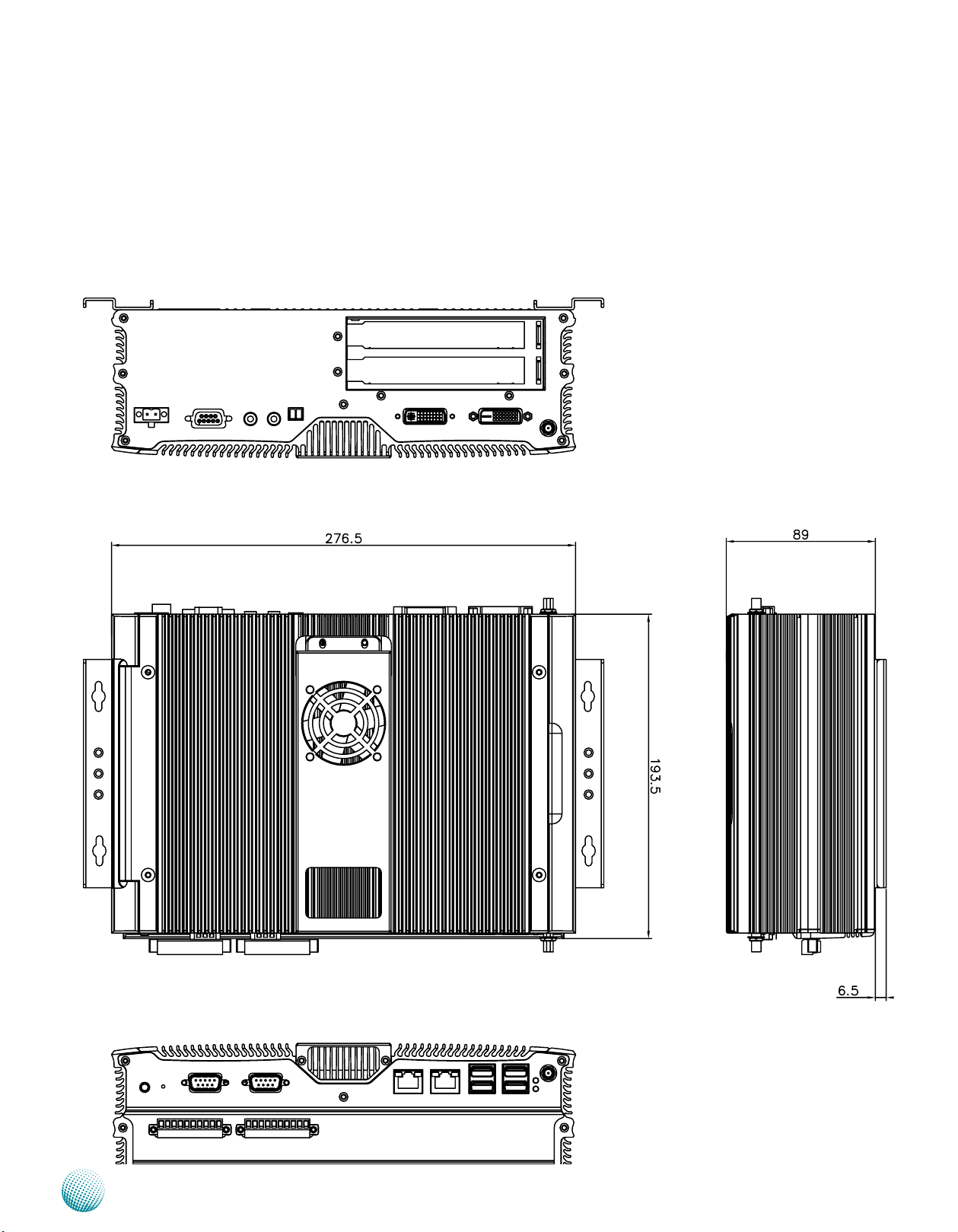
System Drawing
Mechanical dimensions of the LEC-2220P
Unit: mm
7
System Components
Chapter 2
Embedded and Industrial Computing
System Drawing (Continued)
Mechanical dimensions of the LEC-2220P2
Unit: mm

8
System Components
Chapter 2
Embedded and Industrial Computing
Block Diagram
The block diagram depicts the relationships among the
interfaces and modules on the motherboard..

9
System Components
Chapter 2
Embedded and Industrial Computing
Front Components
Component Description Pin Definition Reference
F1 Power Button with dual LED ATX Power-on button with LEDs:
Standby mode in Red; Power-on mode
in Green
F2 Reset Reset switch SW9 on page 17
F3 Serial Ports Serial ports through the DB-9 connector;
COM1 supports RS-232 and COM2
supports RS-232/422/485 with switch
selection among RS-232/422/485.
CN15, CN16 on page 14
F4 Two 10/100/1000Mbps LAN ports Two RJ-45 (network) jacks with LED
indicators as described below. The LAN
ports are provided by Intel 82574L.
They both support WOL/Remote-
wake-up/PXE function.
LINK/ACT (Yellow)
On/Flashing: The port is linking •
and active in data transmission.
Off: The port is not linking.•
SPEED (Green/Amber)
Amber: The connection speed is •
1000Mbps.
Green: The connection speed is •
100Mbps
Off: .The connection speed is •
10Mbps.
LAN Ports (CN13/CN14)
on page 15
F5 Four USB 2.0 Ports An USB type A connector. In addi-•
tion to this connector, an internal
pin header is easily access from the
back compartment where the PCI/
PCIe expansion slot locates.
Dual USB Port Connectors
(USB1, USB2) on Page 16
F6 HDD (Yellow) and
Power L
ED (Green)
HDD
Blinking: data access activities•
Off: no data access activities•
Power
On: The computer is on.•
Off: The computer is off .•
F7 Four Serial Ports COM3 provide RS232/RS422/RS485
communications with a dip switch
selecting among these standards.
COM4~COM6 provide RS232
communication only.
RS-232 COM Port (J9 on
page 15)
F8 Antenna Hole Reserved for antenna
SPEED
LINK/ACT
F1
F2
F3
F4 F5
F7
F6
F8

10
System Components
Chapter 2
Embedded and Industrial Computing
Rear Components
Component Description Pin Definition Reference
R1 DVI-I, DVI-D Dual display with the DVI and DVI-D
ports (single link) which are provided
by Intel HD Graphic Engine through
the Chrontel’s CH7318 SDVO to
DVI converter. The display DVI-I/
DVI-D can support Analog up to
1920x1080 @ 60 Hz and Flat panels
up to 1920x1080 @ 60 Hz
DVI-D/DVI-I Connectors on page
17
R2 Power-on Switch A power-on switch through the
Phoenix contact for distant power-
on/off control
J1 on page 16
R3 MIC IN LINE OUT Connect the audio devices to these
ports. The Microphone and line out
port are provided by Realtek ALC
ALC888S
CN3, CN4 on page 16
R4 DIO Port The DIO port provides 4 digital input
and 4 digital output ports.
CN6 on page 15
R5 DC-In (power) 1x2 Pin
Phoenix Contact Connector
Power-in Connector. The LEC-2220
support power range between
+9~+30V DC-in.
DC_IN Connector (CN5) on page
18
R6 Slot for PCIe/PCI expansion
(*)
The PCIe/PCI expansion capability
is accomplished via the riser card
connected to the system
PCIPCIE1 Connector on page 17
* Model LEC-2220P2 can support 2 PCI expansion.
R6
R4
R2 R3
R5
R1
Loading...