


 Loading...
Network
Application Platforms
Hardware platforms for next generation networking infrastructure
FW-7565
User's Manual
>> |
Publication date:2010-09-01 |

About
Overview
Icon Descriptions
The icons are used in the manual to serve as an indication of interest topics or important messages. Below is a description of these icons:
NOTE: This check mark indicates that there is a note of interest and is something that you should pay special attention to while using the product.
WARNING: This exclamation point indicates that there is a caution or warning and it is something that could damage your property or product.
Online Resources
The listed websites are links to the on-line product information and technical support.
Resource Website
Lanner http://www.lannerinc.com
P r o d u c t http://assist.lannerinc.com Resources
RMA http://eRMA.lannerinc.com
Copyright and Trademarks
This document is copyrighted, © 2010. All rights are reserved. The original manufacturer reserves the right to make improvements to the products described in this manual at any time without notice.
No part of this manual may be reproduced, copied, translated or transmitted in any form or by any means without the prior written permission of the original manufacturer. Information provided in this manual is intended to be accurate and reliable. However, the original manufacturer assumes no responsibility for its use, nor for any infringements upon the rights of third parties that may result from such use.
Network Application Platforms
About
Acknowledgement
Intel, Pentium and Celeron are registered trademarks of Intel Corp.
MicrosoftWindows and MS-DOS are registered trademarks of Microsoft Corp.
All other product names or trademarks are properties of their respective owners.
Compliances
CE
This product has passed the CE test for environmental specifications. Test conditions for passing included the equipment being operated within an industrial enclosure. In order to protect the product from being damaged by ESD (Electrostatic Discharge) and EMI leakage, we strongly recommend the use of CE-compliant industrial enclosure products.
FCC Class A
This equipment has been tested and found to comply with the limits for a Class A digital device, pursuant to Part 15 of the FCC Rules. These limits are designed to provide reasonable protection against harmful interference when the equipment is operated in a commercial environment. This equipment generates, uses and can radiate radio frequency energy and, if not installed and used in accordance with the instruction manual, may cause harmful interference to radio communications. Operation of this equipment in a residential area is likely to cause harmful interference in which case the user will be required to correct the interference at his own expense.
Safety Guidelines
Follow these guidelines to ensure general safety:
•Keep the chassis area clear and dust-free during and after installation.
•Do not wear loose clothing or jewelry that could get caught in the chassis. Fasten your tie or scarf and roll up your sleeves.
•Wear safety glasses if you are working under any conditions that might be hazardous to your eyes.
•Do not perform any action that creates a potential hazard to people or makes the equipment unsafe.
•Disconnect all power by turning off the power and unplugging the power cord before installing or removing a chassis or working near power supplies
•Do not work alone if potentially hazardous conditions exist.
•Never assume that power is disconnected from a circuit; always check the circuit.
i

About
About
LITHIUM BATTERY CAUTION:
Risk of Explosion if Battery is replaced by an incorrect type. Dispose of used batteries according to the instructions
Operating Safety
Electrical equipment generates heat. Ambient air temperature may not be adequate to cool equipment to acceptable operating temperatures without adequate circulation. Be sure that the room in which you choose to operate your system has adequate air circulation.
Ensure that the chassis cover is secure. The chassis design allows cooling air to circulate effectively. An open chassis permits air leaks, which may interrupt and redirect the flow of cooling air from internal components.
Electrostatic discharge (ESD) can damage equipment and impair electrical circuitry. ESD damage occurs when electronic components are improperly handled and can result in complete or intermittent failures. Be sure to follow ESD-prevention procedures when removing and replacing components to avoid these problems.
Wear an ESD-preventive wrist strap, ensuring that it makes good skin contact. If no wrist strap is available, ground yourself by touching the metal part of the chassis.
Periodically check the resistance value of the antistatic strap, which should be between 1 and 10 megohms (Mohms).
EMC Notice
This equipment has been tested and found to comply with the limits for a Class A digital device, pursuant to Part 15 of the FCC Rules. These limits are designed to provide reasonable protection against harmful interference when the equipment is operated in a commercial environment. This equipment generates, uses, and can radiate radio frequency energy and, if not installed and used in accordance with the instruction manual, may cause harmful interference to radio communications. Operation of this equipment in a residential area is likely to cause harmful interference in which case users will be required to correct the interference at their own expense.
Network Application Platforms |
ii |
|
TTaTTable of Contentsbeable of Conten
Chapter 1: Introduction |
|
1 |
System Specification . . . . . . . . . . . . . . . . . . . . . . . . . . . . |
. |
1 |
Package Contents . . . . . . . . . . . . . . . . . . . . . . . . . . . . . . |
|
2 |
Front Panel Features |
|
3 |
Rear Panel Features . . . . . . . . . . . . . . . . . . . . . . . . . . . . . |
|
. 4 |
Chapter 2: Hardware Setup |
|
5 |
Preparing the Hardware Installation |
|
5 |
Installing the System Memory . . . . . . . . . . . . . . . . . . . . . . . . |
. |
5 |
Installing the Hard Disk . . . . . . . . . . . . . . . . . . . . . . . . . . . |
|
. 5 |
Installing a CompactFlash Card |
|
6 |
Installing 3G SIM Card . . . . . . . . . . . . . . . . . . . . . . . . . . . . |
|
7 |
Installing Wireless 3G Module |
|
7 |
Din-Rail Rack Mounting |
|
8 |
Inner Rail Installation . . . . . . . . . . . . . . . . . . . . . . . . . . |
. |
8 |
Outer Rail Installation . . . . . . . . . . . . . . . . . . . . . . . . . . |
. |
9 |
Installing the system to the rack . . . . . . . . . . . . . . . . . . . . . . |
|
9 |
Ear Bracket Rack Mounting . . . . . . . . . . . . . . . . . . . . . . . . . . |
|
9 |
Chapter 3: Motherboard Information |
10 |
|
Block Diagram . . . . . . . . . . . . . . . . . . . . . . . . . . . . . . . |
|
10 |
Motherboard Layout . . . . . . . . . . . . . . . . . . . . . . . . . . . . |
.11 |
|
Jumper Settings . . . . . . . . . . . . . . . . . . . . . . . . . . . . . . |
.12 |
|
Chapter 4: BIOS Settings |
15 |
|
Updating the BIOS |
|
15 |
Accessing the BIOS menu . . . . . . . . . . . . . . . . . . . . . . . . . . |
.16 |
|
Navigating the BIOS menu |
|
16 |
The Main Menu . . . . . . . . . . . . . . . . . . . . . . . . . . . . . |
|
17 |
Advanced Settings |
|
18 |
Boot Setup |
|
35 |
Security Settings . . . . . . . . . . . . . . . . . . . . . . . . . . . . |
.37 |
|
Exit Menu |
|
39 |
Appendix A: Programming Watchdog Timer |
40 |
|
Appendix B: Setting up Console Redirections |
41 |
|
Appendix C: Programming the LCM |
42 |
|
iii
TTaTTable of Contentsbeable of Conten
Appendix D: Programming LAN Bypass |
|
|
|
|
43 |
Appendix E: Driver Installation |
|
|
|
|
44 |
LAN Adapters Driver Installation |
|
|
|
|
44 |
Windows Operating systems . . . . . . . . . . |
. . . . . . . . |
. . |
. . |
. |
44 |
Linux |
|
|
|
|
45 |
VGA Driver Installation . . . . . . . . . . . . . . |
. . . . . . . . . |
. . |
. . |
. |
45 |
Windows Operating systems . . . . . . . . . . |
. . . . . . . . |
. . |
. . |
. |
45 |
Appendix F: Terms and Conditions |
|
|
|
|
46 |
Warranty Policy |
|
|
|
|
46 |
RMA Service |
|
|
|
|
46 |
iv

Chapter 1
Chapter 1:
Introduction
Thank you for choosing the FW-7565. The FW-7565 is a 1U network communication appliance which is built on Intel® Pineview™ embedded processor, the next-generation in the Intel ® Atom™ family. The FW-7565 comes with either 6 or 8 ports of Gigabit Ethernet connection. Both options can come with two pairs of ports supporting abnormal state bypass.
The “Pineview” Atoms bring their memory controllers and graphics cores on-die, saving on power and board size, this makes the FW-7565 an ideal choice for a compact system with power saving.
Please refer to the chart below for a summary of the system’s specifications.
Introduction
System Specification
FEATURE
Form Factor
Platform
OS Support
Storage
Networking
I/O Interface
Expansion
Cooling
Environmental
Parameters
Miscellaneous
Physical
Dimensions
Power
DESCRIPTION
Processor
Chipset
BIOS
Onboard
Socket
HDD Bay(s)
Storage Interface
Ethernet Ports
Chipset
1U Rackmount
Supports Pineview Intel Atom D-510 or D-410
Intel 82801 BHM (ICH8M)
AMI BIOS |
|
|
512 MB/1 GB |
|
Maximum |
|
||
onboard DDRII |
|
|
|
capacity: |
|
667MHz SDRAM |
|
|
|
3GB |
|
(optional) |
|
|
200 pin DDR II |
|
|
667 MHz SO- |
|
|
DIMM |
|
|
|
|
|
Windows (2000, 2003, XP) 32 or 64 bit,
Linux Kernal 2.4 or up
1 x 2.5” or 3.5”
1 x SATA HDD
1 x CompactFlash
6 or 8 GbE
1 x Intel 82574L LAN Chip
5 x Intel 82583V LAN Chip
2 x Intel 82541 PI LAN Chip (models B & D)
Console
USB 2.0
Mini PCIe
Processor
Power Fan
System Fan
Temperature, ambient operating / storage
Humidity (RH), ambient operating and non-operating
LCD Module
Watchdog
Internal RTC with Li Battery
Dimensions (Wx-
HxD)
Weight
Type / Watts
RJ45 x 1
2
1 (USB interface) for 3G / WiFi module
CPU passive heatsink
1
2
0ºC ~40ºC / -20ºC~70ºC
5 ~ 95%, non condensing
Serial LCM
Yes
Yes
430 x 277 x 45mm / 14.1” x 9.1” x 1.5”
7 kg
Single 100W Power Supply
Network Application Platforms |
1 |
|

Chapter 1
Approvals & |
|
|
|
CE Emission, FCC Class A, RoHS |
Compliance |
|
|
|
|
|
|
|
|
|
|
|
|
|
Intel Pineview D-410 (Single Core) |
|
|
FW-7565A |
Processor, |
|
|
|
6 x GbE ports with 2 pair of |
||
|
|
|
|
|
|
|
|
|
Bypass |
|
|
|
|
|
Ordering |
|
|
|
Intel Pineview D-510 (Dual Core) |
|
|
|
Processor, |
|
Information |
|
FW-7565B |
||
|
8 x GbE ports with 2 pair of |
|||
|
|
|
|
|
|
|
|
|
Bypass |
|
|
|
|
|
|
|
|
|
Intel Pineview D-410 (Single Core) |
|
|
FW-7565C |
Processor, |
|
|
|
|
|
6 x GbE ports without bypass |
|
|
|
|
|
|
|
|
|
Intel Pineview D-510 (Dual Core) |
|
|
FW-7565D |
Processor, |
|
|
|
|
|
8 x GbE ports without bypass |
|
|
|
|
|
|
|
|
|
Intel® Pineview-D 510 (Dual Core) |
|
|
FW-7565E |
Processor, |
|
|
|
|
|
6 x GbE Ports with 2 pair Bypass |
Introduction
Package Contents
Your package contains the following items:
•FW-7565 Network Security Platform
•Power cable
•1 crossover Ethernet cable (1.8 meters)
•1 straight-through Ethernet cable (1.8 meters)
•1 RJ-45 to DB-9 female console cable
•Serial-ATA hard drive cable
•1 threaded screw set
•1 ear bracket set
•Drivers and user’s manual CD.
Network Application Platforms |
2 |
|

Chapter 1
Introduction
Front Panel Features
F1 |
F2 |
F3 |
F4 |
F5 |
F6 |
F7 |
Management
L A N 1 L N 2 L A N 3 L A N 4 L A N 5 L A N 6 L A N 7 L A 8
F1 Power/Status/HDD LED
Power: If the LED is on it indicates that the system is powered on. If it is off, it indicates that the system is powered off.
Status: If the LED is green, it indicates that the system’s operational state is normal. If it is red, it indicates that the system is malfunctioning.
HDD: If the LED is on, it indicates that the system’s storage is functional. If the LED blinks, it indicates data access activities. If it is off, it indicates that there is no hard disk present or functional
F2 System Panel: LCD System Panel
The LCD System Panel can be programmed to display operating status and configuration information. For more details or sample programming code, please refer to the Appendix C.
F3 Console Port
By using suitable rollover cable or RJ-45 to DB-9 Female (Cisco console cable), you can connect to a computer terminal for diagnostic or configuration purpose. The default terminal Configuration Parameters: 115200 baud, 8 data bits, no parity, 1 stop bit , no flow control.
F4 Reset Switch
The reset switch can be used to reboot the system without turning off the power. F5 Two USB 2.0 Ports
It connects to any USB devices, for example, a flash drive. The system supports two additional USB 2.0 ports in the form of internal pin headers.
F6 Management Port (Optional)
This FastEthernet port can be connected for configuration or troubleshooting purpose. A conformity with IPMI (Intelligent Platform Management Interface) can be implemented on this interface.
F7 8 Gigabit LAN ports
Right LED:If the LED is orange, it indicates that the connection speed is 1000Mbps. If the LED is green, it indicates that the connection speed is 100Mbps. And if it is off, it indicates that the speed is 10Mbps.
Left LED: If the LED is on, it indicates that the port is active. If it blinks, it indicates there is traffic.
Using suitable RJ-45 cable, you can connect FW-7565 System to a computer, or to any other piece of equipment that has an Ethernet connection, for example, a hub or a switch. Moreover, 2 pairs (LAN1-LAN2, LAN3-LAN4) can be configured as LAN Bypass when failure events occur. This feature is implemented in hardware using watch dog timer functionality. Refer to your Driver and Manual CD for a sample implementation of this feature.
Note:
1.The availability of LAN Bypass varies depending on the model.
2.The number of LAN ports varies depending on the model.
Network Application Platforms |
3 |
|

Chapter 1
Introduction
Rear Panel Features
R1 |
R2 |
R3 |
|||
|
|
|
|
|
|
|
|
|
|
|
|
|
|
|
|
|
|
R1 System Fans 1 and 2
R2 Power-on Switch
It is a switch to turn on or off the power.
R3 AC Power-in socket
It is a power socket from a100-240 AC Power Supply.
Network Application Platforms |
4 |
|
Chapter 2
Chapter 2:
Hardware Setup
Preparing the Hardware Installation
To access some components and perform certain service procedures, you must perform the following procedures first.
 WARNING: To reduce the risk of personal injury, electric shock, or damage to the equipment, remove the power cord to remove power from the device. The Power On/Standby button on the back panel does not completely shut off system power. Portions of the power supply and some internal circuitry remain active until AC power is removed.
1.Unpower the FW-7565 and remove the power cord.
2.Unscrew the 2 threaded screws from the two sides and 2 screws from the rear of the top cover of the FW-7565 System.
3.Slide the cover backwards and lift cover upwards to open it.
2
3
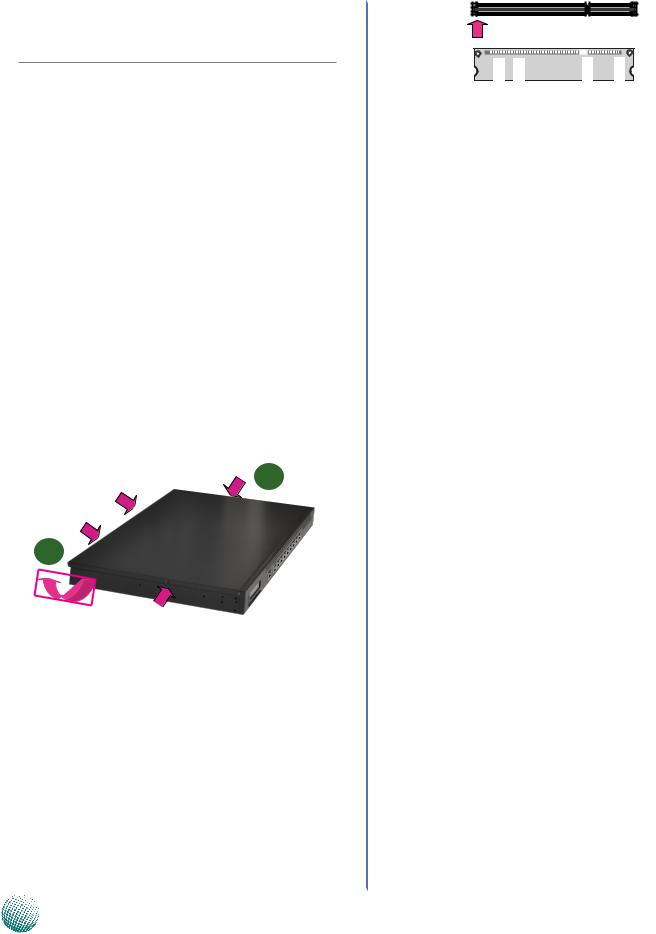
Installing the System Memory
The motherboard supports DDR2 memory that features data transfer rates of 667 or 800 MHz to meet the higher bandwidth requirements of the latest operating system and Internet applications. It comes with one Double Data Rate(DDR2) Small Outline Dual Inline Memory Modules (SO-DIMM) socket.
1.Align the memory module’s cutout with the the SODIMM’s slot notch.
2.Install the SO-DIMM.
Introduction
Notch
Cutout
 Note:
Note:
1.SO-DIMM installed must meet the following speed requirement: DDR2 667 or 800 MHz. Do not install DIMMs with different speeds.
2.The motherboards can accommodate on-board memory of 512MB or 1GB DDR2 memory. With the additional 2GB support from SO-DIMM , it can support a total memory capacity of 3 GB in maximum.
Installing the Hard Disk
The system can accommodate one Serial-ATA disk (2.5” or 3.5”). Follow these steps to install a hard disk into the FW7565:
1.Unscrew the 4 screws on the hard disk tray to take out the hard disk tray from the system.
2.Place hard disk on the hard disk tray and align the holes of the hard disk with the mounting holes on the tray.
3.Secure the hard disk with 4 mounting screws on the hard disk tray.
4.Connect the Serial-ATA power from the ATX power supply unit and hard disk cables to the hard disk’s power and hard drive connectors respectively.
5.Plug the Serial-ATA cable to the Serial-ATA Connector on the main board.
6.Put the hard disk tray with the installed hard disk back to the system and secure it with the mounting screws.
Network Application Platforms |
5 |
|
Chapter 2
5
4
2
3
3
Note: To Secure a 2.5” hard disk on the tray, use the mounting holes on the back .
Introduction
Installing a CompactFlash Card
FW-7565 provides one CompactFlash slot(CN1). Follow the procedures bellow to install a CompactFlash card.
1.Align CompactFlash card and the card slot with the arrow pointing toward the connector.
2.Push the card to insert into the connector.
1 |
2 |
|
Network Application Platforms |
6 |
|

Chapter 2
Introduction
Installing 3G SIM Card
1.Unlock the SIM card tray.
2.Align the SIM card and the tray with the cut-off angle.
3.Insert the SIM card into the tray.
4.Close the tray and lock it on the board.
3
4
Note: To remove the SIM card, unlock the tray first by sliding it outward.
Installing Wireless 3G Module
1.Align the wireless module’s cutout with the Mini-PCIe slot notch.
2.Insert the wireless module into the connector diagnoally.
3.Push the other end of the wireless module to be tightened with the latch.
2
3
 Note: To remove the module from the system, release the latch first by slightly bending it inward.
Network Application Platforms |
7 |
|

Chapter 2
Din-Rail Rack Mounting
 Installation environment precaution:
1.Elevated Operating Ambient - If installed in a closed or multi-unit rack assembly, the operating ambient temperature of the rack environment may be greater
than room ambient. Therefore, consideration should be given to installing the equipment in an environment compatible with the maximum ambient temperature (Tma) specified by the manufacturer.
2.Reduced Air Flow - Installation of the equipment in a rack should be such that the amount of air flow required for safe operation of the equipment is not
compromised. Mechanical Loading - Mounting of the equipment in the rack should be such that a hazardous condition is not created due to uneven mechanical loading.
3.Circuit Overloading - Consideration should be given to the connection of the equipment to the supply circuit and the effect that overloading of the circuits might have on over-current protection and supply wiring. Appropriate consideration of equipment nameplate ratings should be used when addressing this concern.
4.Reliable Earthing - Reliable earthing of rack-mounted equipment should be maintained. Particular attention should be given to supply connections other than direct connections to the branch circuit (e.g. use of power strips).”
 CAUTION :
Slide/rail mounted equipment is not to be used as a shelf or a work space.
Required Tools
1.Philips (cross head) screwdriver (#1 bit and #2 bit)
2.Hex nut driver
3.Anti-static wrist strap and conductive foam pad (recommended)
Din-Rail mounting kit contains the following items:
•2 adjustable outer rail
•2 inner rail with safety stop
*Both outer and inner rail are attached when shipped
•8 crosshead threaded screws
Introduction
Inner Rail Installation
To install the inner rail, separate it from the middle rail first. Follow the following procedures:
1.Place the rails as shown below. The finger tab of extension safety lock should reveal.
2.Press the finger tab and pull the inner rail from the middle rail until they completely separate.
Finger tab
|
|
|
Outer |
|
rail |
|
|
|
|
||
|
|
|
|
||
|
|
|
|||
|
|
|
|
||
Inner rail |
|
||||
|
|
|
|
||
|
|
Middle rail |
|||
3.Turn it inside up, and then hold down the middle extension rail safety lock to stretch the middle rail. Note that the middle rail cannot be separated.
Middle rail extension safety lock
Attaching Din-rails to the chassis
1.Position the inner rail alongside the side of the system’s chassis with the finger tab facing outward and at the rear of the chassis with two notches.
2.Align the screw holes of the rail and the mounting holes of the chassis and then fix the inner rail to the system with crosshead threaded screws.
3.Likewise, attach the other side of the inner rail to the system’s chassis.
Network Application Platforms |
8 |
|

Chapter 2
Outer Rail Installation
Use the following procedures to install the outer rail
1.Attach the rail bracket to the posts of the rack by using two screws (Rail bracket screws are not included, use the original manufacture’s rack bracket screws.) Do not completely tighten the screws; leave them loose to allow for adjustment so that the middle rail can slide.
Tighten the rail bracket to the rack's post with screws
2.Extend the outer back rail to the back of the rack and firmly tighten it with rack bracket screws.
Outer back rail
3.Repeat step 1 and 2 above to install other brackets (2 in the Front and 2 in the Back).
Adjusting the middle rail
1.Adjust the middle rail to about 2.5 inches from the front rack post.
2.5"
Introduction
1.Firmly tighten the Hex nut (4 on each side) on the outer rail after adjusting the middle rail to its proper place..
Installing the system to the rack
1.Fully extend the left and right rails until they are locked by the extension locks firmly.
2.Holding the system with its front facing you, lift the chassis and carefully insert the system with the inner rail attached to the middle rail.
3.Push the chassis all the way toward the back until you hear a click when the rail locks. Hold down the finger tabs to unlock the middle extension safety locks while sliding the system.
Ear Bracket Rack Mounting
 Installation and handling precaution:
1.Installation must be performed only by a trained electrician or by a person who understands all the installation and device specifications, including electrical specifications, which are to be applied.
2.Caution: Do not use the power supply handles to carry the system.”
1.Attach the mounting brackets to the two sides of the system by fastening them with the black screws included in the bracket mounting kit.
2.Align the holes of the ear bracket and mounting holes of the rack.
3.While holding the chassis in place, use appropriate screws to secure it to the rack.
Network Application Platforms |
9 |
|

Chapter 3
Chapter 3:
Motherboard Information
Motherboard Information
Block Diagram
The block diagram depicts the relationships among the interfaces or modules on the motherboard. Please refer to the following figure for your motherboard’s layout design.
Onboard 512 MB/1GB DDR2 667 SDRAM (Optional)
CH 0
1x DDR2 667/800Mhz SO-DIMM
 2 x 6 Pin Header VGA
410 / 510 Processor
X4 DMI
|
|
2x USB 2.0 |
|
|
|
|
|
|
|
|
|
|
|
|
|
|
|
|
|
|
|
|
|
|
|
|
|
|
|
|
|
|
|
|
|
|
|
|
|
|
|
|
|
|
|
|
|
|
|
||||||
|
|
|
|
|
|
|
|
|
|
|
|
|
|
|
|
|
|
|
|
|
|
|
|
|
|
|
|
|
|
|
|
|
|
|
|
|
|
|
|
|
|
|
|
|
|
|
|
||||||||
|
|
|
|
|
|
|
|
|
|
|
|
|
|
|
|
|
|
|
|
|
|
|
|
|
|
|
|
|
|
|
|
|
|
|
|
|
|
|
|
|
|
|
|
|
|
|
|
|
|
||||||
|
|
2x USB 2.0 |
|
|
|
|
|
|
USB 2.0 |
|
|
|
|
|
|
|
|
|
|
|
|
|
|
|
|
|
|
|
|
|
|
|
|
|
|
|
|
|
|
|
|
|
|
|
|
|
|||||||||
|
|
Pin Header |
|
|
|
|
|
|
|
|
|
|
|
|
|
|
|
|
|
|
|
|
|
|
|
|
|
|
|
|
|
|
|
|
|
|
|
|
|
|
|
|
|
|
|
||||||||||
|
|
|
|
|
|
|
|
|
|
|
|
|
|
|
|
|
|
|
|
|
|
|
|
|
|
|
|
|
|
|
|
|
|
|
|
|
|
|
|
|
|
|
CFII socket |
|
|
|
|
|
|
|
|||||
|
|
|
|
|
|
|
|
|
|
|
|
|
|
|
|
|
|
|
|
|
|
|
|
|
|
|
|
|
|
|
|
|
|
|
|
|
|
|
|
|
|
|
|
|
|
|
|
|
|
||||||
|
|
Mini PCI-E Socket |
|
|
|
|
|
|
|
|
|
|
|
|
|
|
|
|
|
|
|
|
|
|
|
|
|
|
|
|
|
|
|
|
|
|
|
|
|
|
|
|
|
||||||||||||
|
|
|
|
|
|
|
|
|
|
|
|
|
|
|
|
|
|
|
|
|
|
|
|
|
|
|
|
|
|
|
|
|
|
|
|
|
|
|
|
|
|
|
|
|
|
|
|
|
|||||||
|
|
|
|
|
|
|
|
|
|
|
|
|
|
|
|
|
|
|
|
|
|
|
|
|
|
|
|
|
|
|
|
|
|
|
|
|
|
|
|
|
|
|
|
|
|
|
|
|
|
|
|
|
|
|
|
|
|
|
|
|
|
|
|
|
|
|
|
|
|
|
|
|
|
|
|
|
|
|
|
|
|
|
|
|
|
|
|
|
|
|
|
|
|
|
|
|
|
|
|
|
|
|
|
|
|
|
|
|
|
|
1x 3.5"or 2.5" |
|
RJ45 Console |
|
|
|
|
|
|
|
|
|
|
|
|
|
|
|
|
|
|
|
|
|
|
|
|
|
|
|
|
|
|
|
|
|
|
|
|
|
|
|
2 x SATA II |
|
|
|
|
|
|
HDD Bay |
|||||||
|
|
|
|
|
|
|
|
|
|
|
|
|
|
|
|
|
|
|
|
|
|
|
|
|
|
|
|
|
|
|
|
|
|
|
|
|
|
|
|
|
|
|
|
|
|
||||||||||
|
Port |
|
|
|
|
|
|
|
|
Winbond |
|
|
|
|
|
|
|
|
|
|
|
|
|
|
|
|
|
|
|
|
|
|
|
|
|
|
|
|
|
|
|
|
|
|
|
|
|
|
|||||||
|
|
|
|
|
|
|
|
|
|
|
|
|
|
|
|
|
|
|
|
|
|
|
|
|
|
|
|
|
|
|
|
|
|
|
|
|
|
|
|
|
|
|
|
|
|
|
|
|
|||||||
|
Console Pin |
|
|
|
|
|
|
|
|
|
|
|
|
|
|
|
|
|
|
|
|
|
|
|
|
|
|
|
|
|
|
|
|
|
|
|
|
|
|
|
|
|
|
|
|||||||||||
|
header |
|
|
|
|
|
|
|
83627THG |
6x PCI-E |
|
|
|
|
|
|
|
|
|
|
|
|
|
|
|
|
|
|
|
2 x PCI |
|
|
|
|
|
|
|
||||||||||||||||||
|
|
|
|
|
|
|
|
|
|
|
|
|
|
|
|
|
|
|
|
|
|
|
|
|
|
|
|
|
|
|
|
|
|
|
|
|
|
|
|
|
|
|
|
||||||||||||
|
KB/Mouse |
|
|
|
|
|
|
|
|
|
|
|
|
|
|
|
|
|
|
|
|
|
|
|
|
|
|
|
|
|
|
|
|
|
|
|
|
|
|
|
|
|
|||||||||||||
|
|
|
|
|
|
|
|
|
|
|
|
|
|
|
|
|
|
|
|
|
|
|
|
|
|
|
|
|
|
|
|
|
|
|
|
|
|
|
|
|
|
|
|
|
|
|
|
|
|
||||||
|
|
|
|
|
|
|
|
|
|
|
|
|
|
|
|
|
|
|
x1 |
|
|
|
|
|
|
|
|
|
|
|
|
|
|
|
|
|
|
|
|
|
|
|
|
|
|
|
|
|
|
|
|
|
|
||
|
|
|
|
|
|
|
|
|
|
|
|
|
|
|
|
|
|
|
|
|
|
|
|
|
|
|
|
|
|
|
|
|
|
|
|
|
|
|
|
|
|
|
|
|
|
|
|
|
|
|
|
|
|
|
|
|
LCM Module |
|
|
|
|
|
|
|
|
|
|
|
|
|
|
|
|
|
|
|
|
|
|
|
|
|
|
|
|
|
|
|
|
|
|
|
|
|
|
|
|
|
|
|
|
|
|
|
|
|
|
|
|
||
|
|
|
|
|
|
|
|
|
|
|
|
|
|
|
|
|
|
|
|
|
|
|
|
|
|
|
|
|
|
|
|
|
|
|
|
|
|
|
|
|
|
|
|
|
|
|
|
|
|
|
|
|
|
|
|
|
|
|
|
|
|
|
|
|
|
|
|
Intel |
|
|
Intel |
|
Intel |
|
Intel |
|
Intel |
|
Intel |
|
Intel |
|
Intel |
|
|||||||||||||||||||||||||||
|
|
|
|
|
|
|
|
|
|
|
82574L |
|
|
82583V |
|
82583V |
|
82583V |
|
82583V |
|
82583V |
|
82541PI |
|
82541PI |
|
||||||||||||||||||||||||||||
|
|
|
|
|
|
|
|
|
|
|
|
|
|
|
|
|
|
|
|
|
|
|
|
|
|
|
|
|
|
|
|
|
|
|
|
|
|
|
|
|
|
|
|
|
|
|
|
|
|
|
|
|
|
|
|
|
|
|
|
|
|
|
|
|
|
|
|
|
|
|
|
|
|
|
|
|
|
|
|
|
|
|
|
|
|
|
|
|
|
|
|
|
|
|
|
|
|
|
|
|
|
|
|
|
|
|
|
|
|
|
|
|
|
|
|
|
|
|
|
|
|
|
|
|
|
|
|
|
|
|
|
|
|
|
|
|
|
|
|
|
|
|
|
|
|
|
|
|
|
|
|
|
|
|
|
|
|
|
|
|
|
|
|
|
|
|
|
6 x GbE RJ-45 LAN Ports |
|
|
|
Additional |
|
|
|
2 x GbE RJ-45 Ports |
|
|
|
|||
With 2 Pairs Bypass ( A, B, E only) |
|
|
|
( B & D only) |
Network Application Platforms |
10 |
|

Chapter 3
Motherboard Information
Motherboard Layout
The motherboard layout shows the connectors and jumpers on the board. Refer to the following picture as a reference of the pin assignments and the internal connectors.
VGA Interface
M7 |
|
|
Compact Flash Connector |
Fan1 and Fan2 Connec- |
|
||
|
|
||
|
tor |
Clear CMOS |
M10 |
M4 |
M9 |
|
|||
|
|
|
M11 |
||
|
|
|
|
|
|
|
|
|
|
|
|
|
|
|
|
|
Serial Port |
|
|
|
|
|
|
|
|
|
|
|
|
|
|
|
|
|
|
|
|
|
|
|
Connector |
M1 |
SO-DIMM |
|
|
|
|
|
|
|
|
|
||||||
|
|
|
|
|
|
|
|
|
||||||||
|
|
|
Socket |
|
|
|
|
|
|
|
USB 3 and 4 |
|
||||
|
|
|
|
|
|
|
|
|
|
|
|
|
|
M12 |
||
|
|
|
|
|
|
|
|
|
|
|
|
|
|
Connectors |
||
|
|
|
|
|
|
|
|
|
|
|
|
|
|
Serial Port Con- |
M13 |
|
|
|
|
|
|
|
|
|
|
|
|
|
|
|
nector |
M14 |
|
|
|
|
Power Switch Con- |
|
|
|
|
|
|
Keyboard and |
||||||
|
|
|
|
|
|
|
|
|
||||||||
|
|
|
|
|
|
|
|
|
|
|||||||
M2 |
|
|
|
|
|
|
Mouse Connec- |
|
||||||||
nector |
|
|
|
|
|
|
|
|
|
|
||||||
|
|
|
|
|
|
|
|
|
|
tors |
|
|||||
|
|
|
|
|
|
|
|
|
|
|
|
|
|
SIM Card |
|
M15 |
M3 |
|
|
|
|
|
|
|
|
|
|
|
connector |
|
M16 |
||
ATX Power |
|
|
|
|
|
|
Mini PCI-E |
|||||||||
|
|
|
|
|
|
|
||||||||||
|
|
|
|
|
|
Connector |
|
|||||||||
|
|
|
Connector |
|
|
|
|
|
|
|
|
|||||
|
|
|
|
|
|
|
|
|
|
|
|
|||||
M8 |
Fan3 |
|
|
|
|
|
|
|
|
|
||||||
Connector |
|
|
|
|
|
|
|
|
|
|
||||||
|
|
|
|
|
|
|
|
|
|
|
|
|
|
|
|
|
M5
M6 |
Reset |
|
Switch |
|
|
|
|
|
|
|
|||
|
|
|
|
M17 |
||
|
|
|
|
|
|
|
Hardware and Software |
|
|
|
|
|
Ethernet Ports |
|
|
|
|
|||
Reset jumper |
|
|
USB2.0 Ports |
|||
|
|
|
|
|
|
|
Network Application Platforms |
11 |
|
Loading...