


LEC-2010 Fanless Embedded System User’s Manual
LEC-2010 Series
Intel® Atom N270 (1.6Ghz) CPU onboard Fanless Embedded System
User’s Manual
1
LEC-2010 Fanless Embedded System User’s Manual
LEC-2010 Series
User’s Manual
Version 1.1
© Copyright 2009, Lanner Electronics, Inc. All rights reserved. This document contains proprietary information that is protected by copyright. No part of this document may be reproduced, transmitted, transcribed, stored in a retrieval system, or translated into any language in any form by any means without the written express of Lanner Electronics, Inc. The author and Lanner Electronics, Inc. have used their best efforts in preparing this manual. However, the author and Lanner Electronics, Inc. make no warranties of any kind, expressed or implied, with regard to the informational content, documentation, or files contained in this manual, and shall not be liable for technical or editorial errors or omissions contained herein. In no event shall the author or publisher be responsible or liable for any incidental or consequential damages resulting from the furnishing, performance, or use of this material.
TRADEMARKS Internet Explorer, Windows Explorer, and Windows are trademarks or registered trademarks of Microsoft Corporation. Other products mentioned herein may be trademarks/or registered trademarks of their respective owners.
2
LEC-2010 Fanless Embedded System User’s Manual
Safety Guidelines
Follow these guidelines to ensure general safety:
Keep the chassis area clear and dust-free during and after installation.
Do not wear loose clothing or jewelry that could get caught in the chassis. Fasten your tie or scarf and roll up your sleeves.
Wear safety glasses if you are working under any conditions that might be hazardous to your eyes.
Do not perform any action that creates a potential hazard to people or makes the equipment unsafe.
Disconnect all power by turning off the power and unplugging the power cord before installing or removing a chassis or working near power supplies
Do not work alone if potentially hazardous conditions exist.
Never assume that power is disconnected from a circuit; always check the circuit.
LITHIUM BATTERY CAUTION:
Risk of Explosion if Battery is replaced by an incorrect type. Dispose of used batteries according to the instructions.
Operating Safety
Electrical equipment generates heat. Ambient air temperature may not be adequate to cool equipment to acceptable operating temperatures without adequate circulation. Be sure that the room in which you choose to operate your system has adequate air circulation.
Ensure that the chassis cover is secure. The chassis design allows cooling air to circulate effectively. An open chassis permits air leaks, which may interrupt and redirect the flow of cooling air from internal components.
Electrostatic discharge (ESD) can damage equipment and impair electrical circuitry. ESD damage occurs when electronic components are improperly handled and can result in complete or intermittent failures. Be sure to follow ESD-prevention procedures when removing and replacing components to avoid these problems.
Wear an ESD-preventive wrist strap, ensuring that it makes good skin contact. If no wrist strap is available, ground yourself by touching the metal part of the chassis.
Periodically check the resistance value of the antistatic strap, which should be between 1 and 10 megohms (Mohms).
3
LEC-2010 Fanless Embedded System User’s Manual
EMC Notice
This equipment has been tested and found to comply with the limits for a Class A digital device, pursuant to Part 15 of the FCC Rules. These limits are designed to provide reasonable protection against harmful interference when the equipment is operated in a commercial environment. This equipment generates, uses, and can radiate radio frequency energy and, if not installed and used in accordance with the instruction manual, may cause harmful interference to radio communications. Operation of this equipment in a residential area is likely to cause harmful interference in which case users will be required to correct the interference at their own expense.
Class A Notice for FCC
Modifying the equipment without the authorization of Lanner Electronics, Inc. may result in the equipment no longer complying with FCC requirements for Class A digital devices. In that event, your right to use the equipment may be limited by FCC regulations, and you may be required to correct any interference to radio or television communications at your own expense.
This equipment is in compliance with the essential requirements and other relevant provisions of Directive 1999/5/EC.
4
LEC-2010 Fanless Embedded System User’s Manual
Contents
Safety Guidelines.......................................................................... |
3 |
||
EMC Notice .................................................................................. |
4 |
||
Contents...................................................................................... |
5 |
||
Document History ......................................................................... |
6 |
||
1. |
Product Overview ..................................................................... |
7 |
|
1.1 |
|
Product Introduction ............................................................. |
7 |
1.2 |
|
Features and Benefits............................................................ |
7 |
1.3 |
|
Specifications....................................................................... |
8 |
1.4 |
|
Block Diagram...................................................................... |
9 |
1.5 |
|
Package Contents ............................................................... |
10 |
1.6 |
|
Technical Assistance ........................................................... |
11 |
2. System Components............................................................... |
12 |
||
2.1 |
LEC-2010 Embedded System Mechanisms.............................. |
12 |
|
2.1.1 |
Front View ...................................................................... |
13 |
|
2.1.2 |
Rear View ....................................................................... |
13 |
|
2.2 |
|
LEB-2010 System Board .................................................... |
14 |
2.2.1 |
Board View ..................................................................... |
15 |
|
2.2.2 |
Jumper Settings and I/O Connectors .................................... |
16 |
|
2.2.3 |
Connector Pin Assignments ............................................... |
17 |
|
3. |
Hardware Installation Guide..................................................... |
42 |
|
3.1 |
|
LEC-2010 Embedded System ............................................... |
42 |
3.1.1 |
Begin Installation............................................................. |
43 |
|
3.1.2 |
System Memory Installation .............................................. |
45 |
|
3.1.3 |
CompactFlash Card Installation.......................................... |
45 |
|
3.1.4 |
PCI Module Installation ..................................................... |
46 |
|
3.1.5 LEC-2010 Hard Disk Installation......................................... |
49 |
||
3.1.6 System Installation is now Complete .................................. |
52 |
||
3.2 |
|
Mounting Kits .................................................................... |
55 |
3.2.1 |
Wall Mount View .............................................................. |
55 |
|
3.2.2 Wall Mount Package and Ordering Information ..................... |
55 |
||
A. Appendix A: LED Indicators ..................................................... |
56 |
||
A.1 |
LAN Port LED ...................................................................... |
56 |
|
A.2 |
Power-on Button LED ........................................................... |
56 |
|
A.3 |
HDD LED............................................................................ |
57 |
|
A.4 |
POWER LED ........................................................................ |
57 |
|
B. Appendix B: Watchdog Timer................................................... |
58 |
||
B.1 |
Introduction ....................................................................... |
58 |
|
B.2 |
Detail Register Descriptions .................................................. |
58 |
|
B.2.1 To use the watch-dog timer .............................................. |
58 |
||
C. Appendix C: DIO.................................................................... |
61 |
||
C.1 To use the DIO ................................................................... |
61 |
||
Terms and Conditions.................................................................. |
65 |
||
Warranty Policy .......................................................................... |
65 |
||
RMA Service :............................................................................. |
65 |
||
Requesting a RMA#..................................................................... |
65 |
||
|
|
5 |
|
LEC-2010 Fanless Embedded System User’s Manual
Document History
Date |
Revision |
Comment |
|
|
|
|
|
2009/10/5 |
V1.1 |
Modify USBG1 Pin assignment (Pin 5) |
|
Adding MIC IN/LINE OUT pin assignment |
|||
|
|
||
|
|
|
|
|
|
|
|
|
|
|
|
|
|
|
|
|
|
|
|
|
|
|
|
|
|
|
6

LEC-2010 Fanless Embedded System User’s Manual
1. Product Overview
1.1Product Introduction
Figure 1 – LEC-2010 Outlook
The Lanner LUGE LEC-2010 is a fanless embedded system designed for intelligent industrial and commercial applications. It features extensive I/O interfaces, PCI or PCI Express expansion slot, and an onboard Intel® Atom™ embedded processor for exceptional performance with very low heat generation and minimal cooling requirements, resulting in improved stability and longevity, and providing a higher return on investment.
1.2Features and Benefits
Fanless embedded system
Intel Atom 1.6GHz onboard CPU
VGA, DVI-D video out
6 COM ports, 7 USB port
Supports up to 2GB DDR2 memory
Dual GbE LAN
PCI or PCI-E expansion slot
CompactFlash Type I/II and SATA HDD support
7

LEC-2010 Fanless Embedded System User’s Manual
1.3Specifications
Feature |
|
|
Description |
|
|
|
|
||
|
|
|
|
|
Form Factor |
|
Fanless Embedded System |
|
|
|
|
|
|
|
|
|
Processor |
Onboard Intel® Atom™ 1.6 GHz |
|
Platform |
|
Chipset |
Intel 945GSE+ICH7M |
|
|
|
BIOS |
AMIBIOS with 8Mbit BIOS Flash |
|
|
|
|
|
|
|
|
Technology |
533 MHz DDR2 SDRAM |
|
System Memory |
|
Socket |
200P SODIMM x1 |
|
|
Onboard Memory |
1GB DDR2 onboard |
|
|
|
|
|
||
|
|
Maximum Capacity |
2GB (1GB DDR2 onboard + 1GB DDR2 module) |
|
|
|
|
|
|
Storage Interface |
|
CompactFlash I/II |
1 |
|
|
SATA Port |
2 |
|
|
|
|
|
||
|
|
|
|
|
Display |
|
Interface |
VGA D-Sub 15-pin connector |
|
|
DVI-D |
|
||
|
|
|
||
Audio |
|
Codec |
ALC888 HD Codec |
|
|
|
|
|
|
Networking |
|
Lan Ports |
2 |
|
|
Speed |
10/100/1000 Mbps |
|
|
|
|
|
||
|
|
|
|
|
|
|
Digital I/O |
DB9 Female 4 in 4 Out |
|
Front I/O |
|
USB 2.0 |
6 (Total: 7; External x 6 , Internal x 1) |
|
|
LAN |
2 x RJ45 GbE |
|
|
|
|
|
||
|
|
Mic In / Line Out |
1/1 |
|
|
|
|
|
|
|
|
COM |
RS-232 x 4; RS-232/422/485 selectable x 2 ports(COM2& |
3) |
Rear I/O |
|
DVI |
1 |
|
|
|
VGA |
1 |
|
Internal I/O |
|
USB 2.0 |
1 (Pin header) |
|
Expansion |
|
Lan Ports |
PCI x 1 (LEC-2010P) |
|
|
|
Lan Ports |
PCIe x 1 (LEC-2010E) |
|
|
|
Speed |
Mini-PCIe x 1 |
|
Hardware |
|
Controller |
Winbond W83627UHG integrated hardware monitor |
|
Monitoring |
|
Watchdog timer |
Reset supported, 1~255 level |
|
|
|
|
|
|
OS Supported |
|
|
Linux kernel 2.4.16 or above, XPE/Win |
|
|
|
XP-32 bit, Win CE 6.0 |
|
|
|
|
|
|
|
|
|
|
|
|
|
|
Temperature, ambient |
-5~45°C (with 2.5” commercial HDD) |
|
|
|
operating |
-10°~55°C (with industrial components - CF card, HDD, |
|
|
|
|
Memory, adapter) |
|
Environmental |
|
|
Extended Operating Temperature: |
|
|
|
-20°C: 24 hours bootable; |
|
|
Parameters |
|
|
|
|
|
|
70° C: 72 hours full-loading operating |
|
|
|
|
|
|
|
|
|
Humidity (RH), ambient |
10~95% relative humidity, non-condensing |
|
|
|
operating |
|
|
|
|
Storage Temperature |
-20°~80°C |
|
Mounting |
|
|
Wall mounting kit |
|
|
|
|
|
|
Physical Dimensions |
|
Dimensions |
268(W) x 65(H) x 190(D) |
|
|
|
Net Weight |
2.6Kg |
|
Power |
|
Input |
DC +9V~36V (ATX Mode) |
|
|
Adapter |
75W (+19V) |
|
|
|
|
|
||
|
|
|
|
|
Note: All specifications and images are subject to change without notice.
8

LEC-2010 Fanless Embedded System User’s Manual
1.4Block Diagram
Figure 2 – Block Diagram
9

LEC-2010 Fanless Embedded System User’s Manual
1.5Package Contents
Carefully unpack your package and make sure that you have the following items:
Item |
Package Contents |
Q'ty |
|
|
|
|
|
Photo |
Ordering Information |
|||||||
|
|
|
|
|
|
|
|
|
|
|
|
|
|
|
*LEC-2010P |
|
1 |
LEC-2010 Embedded System |
1 |
|
|
|
|
|
|
|
|
|
|
|
|
(for PCI Riser |
card) |
|
|
|
|
|
|
|
|
|
|
|
|
*LEC-2010E |
|
|||
|
|
|
|
|
|
|
|
|
|
|
|
|
|
|
|
|
|
|
|
|
|
|
|
|
|
|
|
|
|
|
|
(for PCIe Riser |
card) |
2 |
DC+19V 75W Power Adapter |
1 |
|
|
|
|
|
|
|
|
|
|
|
|
|
|
|
|
|
|
|
|
|
|
|
|
|
|
|
|
|||
|
|
|
|
|
|
|
|
|
|
|
|
|
|
|
*P/N:0P0W075190001 |
|
|
|
|
|
|
|
|
|
|
|
|
|
|
|
|
||
3 |
Serial ATA/Power Cable |
1 |
|
|
|
|
|
|
|
|
|
|
|
|
|
|
|
|
|
|
|
|
|
|
|
|
|
|
|
|
|||
|
|
|
|
|
|
|
|
|
|
|
|
|
|
|
*P/N:080W1N2201001 |
|
|
|
|
|
|
|
|
|
|
|
|
|
|
|
|
||
4 |
HDD Screw ( M3x8) |
4 |
|
|
|
|
|
|
|
|
|
|
|
|
|
|
|
|
|
|
|
|
|
|
|
|
|
|
|
|
|||
|
|
|
|
|
|
|
|
|
|
|
|
|
|
|
*P/N:070W102400801 |
|
|
|
|
|
|
|
|
|
|
|
|
|
|
|
|
||
5 |
Wall Mount Screw (M3x6 Ni) |
4 |
|
|
|
|
|
|
|
|
|
|
|
|
|
|
|
|
|
|
|
|
|
|
|
|
|
|
|
|
|||
|
|
|
|
|
|
|
|
|
|
|
|
|
|
|
*P/N:070W103000601 |
|
|
|
|
|
|
|
|
|
|
|
|
|
|
|
|
||
6 |
Wall Mount Kits |
1 |
|
|
|
|
|
|
|
|
|
|
|
|
|
|
|
|
|
|
|
|
|
|
|
|
|
|
|
|
|||
(Please check chapter 3.2.1) |
|
|
|
|
|
|
|
|
|
|
|
|
|
|
||
|
|
|
|
|
|
|
|
|
|
|
|
|
|
|
*P/N:SE9ESA829R110 |
|
|
|
|
|
|
|
|
|
|
|
|
|
|
|
|
||
7 |
Terminal Block (10 pin) |
2 |
|
|
|
|
|
|
|
|
|
|
|
|
|
|
|
|
|
|
|
|
|
|
|
|
|
|
|
|
|||
|
|
|
|
|
|
|
|
|
|
|
|
|
|
|
*P/N:04AW20101O101 |
|
|
|
|
|
|
|
|
|
|
|
|
|
|
|
|
||
8 |
Terminal Block (2 pin) |
1 |
|
|
|
|
|
|
|
|
|
|
|
|
|
|
|
|
|
|
|
|
|
|
|
|
|
|
|
|
|||
|
|
|
|
|
|
|
|
|
|
|
|
|
|
|
*P/N:04AW20024E101 |
|
|
|
|
|
|
|
|
|
|
|
|
|
|
|
|
||
9 |
Drivers and User’s Manual CD |
1 |
|
|
|
|
|
|
|
|
|
|
|
|
|
|
|
|
|
|
|
|
|
|
|
|
|
|
|
|
|||
|
|
|
|
|
|
|
|
|
|
|
|
|
|
|
*LEC-2010 CD |
|
|
|
|
|
|
|
|
|
|
|
|
|
|
|
|
|
|
10 |
Carton(Inside) |
1 |
|
|
|
|
|
|
|
|
|
|
|
|
|
|
|
|
|
|
|
|
|
|
|
|
|
|
|
|
|||
|
(Dimension:359x333x164mm) |
|
|
|
|
|
|
|
|
|
|
|
|
|
|
|
|
|
|
|
|
|
|
|
|
|
|
|
|
|
|
*P/N:085W002204107 |
|
|
|
|
|
|
|
|
|
|
|
|
|
|
|
|
||
|
|
|
|
|
|
|
|
|
|
|
|
|
|
|
||
11 |
Carton(Outside) |
1 |
|
|
|
|
|
|
|
|
|
|
|
|
|
|
|
|
|
|
|
|
|
|
|
|
|
|
|
|
|||
|
(Dimension:370x351x191mm) |
|
|
|
|
|
|
|
|
|
|
|
|
|
*P/N:085W002104239 |
|
|
|
|
|
|
|
|
|
|
|
|
|
|
|
|
||
*Total Weight of packing: NW:2.62kgs ; GW: 4kgs |
|
|
||||||||||||||
|
|
|
|
|
|
|
|
|
|
|
|
|
|
|
|
|
Note: If you should find any components missing or damaged, please contact your dealer immediately for assistance.
10
LEC-2010 Fanless Embedded System User’s Manual
1.6Technical Assistance
Should you have any questions or problems with your product, please contact the Lanner sales team.
Phone: 886-2-8692-6060
Fax: 886-2-8692-6101
E-mail: support@lannerinc.com
Prior to contacting us, we ask that you first check the electronic product documentation for assistance. Should you still have questions, we recommend you have the following information on hand in order to expedite the process:
1.LEC-2010 model name
2.Serial number
3.Local network configuration details
4.Abnormal behavior and/or error messages reported by your network system
5.Your questions, or a description of the problem you are experiencing
11

LEC-2010 Fanless Embedded System User’s Manual
2. System Components
2.1LEC-2010 Embedded System Mechanisms
This section of the manual describes the mechanical and device nomenclature of the LEC-2010.
Figure 3 – LEC-2010 System
12

LEC-2010 Fanless Embedded System User’s Manual
2.1.1Front View
Figure4 – LEC-2010 Front View
2.1.2Rear View
Figure 5– LEC-2010 Rear View
13

LEC-2010 Fanless Embedded System User’s Manual
2.2LEB-2010 System Board
LEB-2010 is the system board bundled with the LEC-2010 Fanless Embedded System platform. The succeeding sections list LEB-2010 related jumper settings and connector pin assignments.
Figure 6 – LEB-2010 System Board
14

LEC-2010 Fanless Embedded System User’s Manual
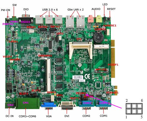
2.2.1Board View
SC2T2 |
Select COM2 Type Jumper |
CF1 |
Compact Flash Connector |
SC2T1 |
Select COM2 Type Jumper |
CCMOS1 |
Clear CMOS Data Jumper |
PCOM1 |
Select COM1 Pin9 Signal Jumper |
CARPSC1 |
Car Application 5-Pin Power Connector |
KM1 |
Keyboard/Mouse Connector Header |
MPCIE1 |
Mini PCI Express 1X Connector |
USBG1 |
USB Port#7 5-Pin Power Connector |
PCIGF1 |
120 Pin PCI Golden Finger |
SODIMM1 |
200 PIN DDR2 SODIMM Socket |
PCIEGF1 |
PCI Express 1x Golden Finger |
SC3T2 |
Select COM3 Type Jumper |
COM1/2 |
Serial Port COM1/2 Connector |
SC3T1 |
Select COM3 Type Jumper |
CN1 |
COM3 ~ 6 Connector |
VLCD1 |
Select Panel Voltage Header |
CN2 |
DC-IN Connector |
INVER1 |
7 Pin LCD INVETER Connector |
DGIO1 |
DIO Connector |
LVDS1 |
LVDS Connector |
PSW1 |
SW Connector |
PS4S1 |
4-Pin Power Connector |
PSBTN1 |
PW-ON Button |
SATA2 |
Serial ATA-SATA Socket |
MIC1 |
MIC IN Connector |
SATA1 |
Serial ATA-SATA Socket |
LNO1 |
LINE OUT Connector |
Figure 6 – LEB-2010 Board View
15
LEC-2010 Fanless Embedded System User’s Manual
2.2.2 Jumper Settings and I/O Connectors
The jumper settings and I/O connectors of the LEC-2010 have been arranged at the factory. Any changes to the schematic or design of these connectors may cause damage to your unit.
Jumper Settings and I/O Connector Summary for LEC-2010 is as below:
CHAPTER |
JUMPER |
FUNCTION |
2.2.3.1 |
SC2T2 |
Select COM2 Type Jumper |
2.2.3.2 |
SC2T1 |
Select COM2 Type Jumper |
2.2.3.3 |
PCOM1 |
Select COM1 Pin9 Signal Jumper |
2.2.3.4 |
KM1 |
Keyboard/Mouse Connector Header |
2.2.3.5 |
USBG1 |
USB Port#7 5-Pin Power Connector (5P Male) |
2.2.3.6 |
SODIMM1 |
200 PIN DDR2 SODIMM Socket |
2.2.3.7 |
SC3T2 |
Select COM3 Type Jumper |
2.2.3.8 |
SC3T1 |
Select COM3 Type Jumper |
2.2.3.9 |
VLCD1 |
Select Panel Voltage Header (Reserved) |
2.2.3.10 |
INVER1 |
7 Pin LCD INVETER Connector (Optional) |
2.2.3.11 |
LVDS1 |
LVDS Connector (Optional) |
2.2.3.12 |
PS4S1 |
4-Pin Power Connector (4P Male ) |
2.2.3.13 |
SATA2 |
Serial ATA-SATA Socket (Port 2) |
2.2.3.13 |
SATA1 |
Serial ATA-SATA Socket (Port 1) |
2.2.3.14 |
LNI1 |
Line In 3Pin Connector |
2.2.3.15 |
CF1 |
Compact Flash Connector |
2.2.3.16 |
CCMOS1 |
Clear CMOS Data Jumper |
2.2.3.17 |
CARPSC1 |
Car Application 5-Pin Power Connector (5P Male) |
2.2.3.18 |
MPCIE1 |
Mini PCI Express 1X Connector |
2.2.3.19 |
PCIGF1 |
120 Pin PCI Golden Finger |
2.2.3.20 |
PCIEGF1 |
PCI Express 1x Golden Finger |
2.2.3.21 |
COM1/2 |
Serial Port COM1/2 Connector (D-SUB9 Male) |
2.2.3.22 |
CN1 |
COM3 – 6 Connector |
2.2.3.23 |
CN2 |
DC-IN Connector (9 ~ 36V) |
2.2.3.24 |
DGIO1 |
DIO Connector ( D-SUB9 Female) |
2.2.3.25 |
PSW1 |
SW Connector (ATX Power Switch Connector) |
2.2.3.26 |
PSBTN1 |
PW-ON Button |
2.2.3.27 |
MIC1 |
MIC IN Connector |
2.2.3.28 |
LNO1 |
LINE OUT Connector |
16

LEC-2010 Fanless Embedded System User’s Manual
2.2.3Connector Pin Assignments
2.2.3.1 SC2T2: Select COM2 Type Jumper
COM2 TYPE |
SC2T2 |
|
|
RS-232 (Default) |
1-5,2-6,3-7,4-8 |
RS-422 |
5-9,6-10,7-11,8-12 |
RS-485 |
5-9,6-10,7-11,8-12 |
17

LEC-2010 Fanless Embedded System User’s Manual
2.2.3.2 SC2T1: Select COM2 Type Jumper
COM2 TYPE |
SC2T1 |
|
|
RS-232 (Default) |
1-2 |
RS-422 |
3-4 |
RS-485 |
5-6 |
18
LEC-2010 Fanless Embedded System User’s Manual
2.2.3.3 PCOM1 : Select COM1 Pin9 Signal Jumper
Description |
PCOM1 |
Ring In |
1-2 (Default) |
+5V |
3-4 |
+12V |
5-6 |
19

LEC-2010 Fanless Embedded System User’s Manual
2.2.3.4 KM1 Keyboard/Mouse Connector Header
(for Factory test only)
Pin No. |
Description |
Pin No. |
Description |
1 |
+5V |
2 |
MSCLK |
3 |
MSDATA |
4 |
KEY |
5 |
KBDAT |
6 |
KEY |
7 |
GND |
8 |
KBCLK |
20
 Loading...