


Network
Application Platforms
Hardware platforms for next generation networking infrastructure
FW-7525
V1.1
User's Manual
Release Date: 2015/05/08

Overview
Icon Descriptions
The icons are used in the manual to serve as an indication of interest topics or important messages. Below is a description of these icons:
NOTE: This check mark indicates that there is a note of interest and is
something that you should pay special attention to while using the product.
WARNING: This exclamation point indicates that there is a caution or warning and it is something that could damage your property or product.
Online Resources
The listed websites are links to the on-line product information and technical support.
Resource |
Website |
|
|
Lanner |
http://www.lannerinc.com |
Product |
http://www.lannerinc.com/download- |
Resources |
center/ |
RMA |
http://eRMA.lannerinc.com |
|
|
Copyright and Trademarks
This document is copyrighted, © 2014. All rights are reserved. The original manufacturer reserves the right to make improvements to the products described in this manual at any time without notice.
No part of this manual may be reproduced, copied, translated or transmitted in any form or by any means without the prior written permission of the original manufacturer. Information provided in this manual
is intended to be accurate and reliable. However, the original manufacturer assumes no responsibility for its use, nor for any infringements upon the rights of third parties that may result from such use.
Acknowledgement
Intel, Pentium and Celeron are registered trademarks of Intel Corp.
Microsoft Windows and MS-DOS are registered trademarks of Microsoft Corp.
All other product names or trademarks are properties of their respective owners.
Compliances
CE
This product has passed the CE test for environmental specifications. Test conditions for passing included the equipment being operated within an industrial enclosure. In order to protect the product from being damaged by ESD (Electrostatic Discharge) and EMI leakage, we strongly recommend the use of CEcompliant industrial enclosure products.
FCC Class B
This equipment has been tested and found to comply with the limits for a Class B digital device, pursuant to Part 15 of the FCC Rules. These limits are designed to provide reasonable protection against harmful interference when the equipment is operated in in a residential environment.This equipment generates,
uses and can radiate radio frequency energy and, if not installed and used in accordance with the instruction manual, may cause harmful interference to radio communications. Operation of this equipment in a commercial area is likely to cause harmful interference in which case the user will be required to correct the interference at his own expense.
Safety Guidelines
Follow these guidelines to ensure general safety:
•Keep the chassis area clear and dust-free during and after installation.
•Do not wear loose clothing or jewelry that could get caught in the chassis. Fasten your tie or scarf and roll up your sleeves.
•Wear safety glasses if you are working under any conditions that might be hazardous to your eyes.
•Do not perform any action that creates a potential hazard to people or makes the equipment unsafe.
•Disconnect all power by turning off the power and unplugging the power cord before installing or removing a chassis or working near power supplies
•Do not work alone if potentially hazardous conditions exist.
•Never assume that power is disconnected from a circuit; always check the circuit.
LITHIUM BATTERY CAUTION:
Risk of Explosion if Battery is replaced by an incorrect type. Dispose of used batteries according to the instructions
Operating Safety
Electrical equipment generates heat. Ambient air temperature may not be adequate to cool equipment to acceptable operating temperatures without adequate circulation. Be sure that the room in which you choose to operate your system has adequate air circulation.
Ensure that the chassis cover is secure. The chassis design allows cooling air to circulate effectively. An open chassis permits air leaks, which may interrupt and redirect the flow of cooling air from internal components.
Electrostatic discharge (ESD) can damage equipment and impair electrical circuitry. ESD damage occurs when electronic components are improperly handled and can result in complete or intermittent failures. Be sure to follow ESD-prevention procedures when removing and replacing components to avoid these problems.
Wear an ESD-preventive wrist strap, ensuring that it makes good skin contact. If no wrist strap is available, ground yourself by touching the metal part of the chassis.
Periodically check the resistance value of the antistatic strap, which should be between 1 and 10 megohms (Mohms).
EMC Notice
This equipment has been tested and found to comply with the limits for a Class B digital device, pursuant to Part 15 of the FCC Rules. These limits are designed to provide reasonable protection against harmful interference when the equipment is operated in a residential environment. This equipment generates,
uses, and can radiate radio frequency energy and, if not installed and used in accordance with the instruction manual, may cause harmful interference to radio communications. Operation of this equipment in a commercial area is likely to cause harmful interference in which case users will be required to correct the interference at their own expense.
Consignes de sécurité
Suivez ces consignes pour assurer la sécurité générale :
•Laissez la zone du châssis propre et sans poussière pendant et après l’installation.
•Ne portez pas de vêtements amples ou de bijoux qui pourraient être pris dans le châssis. Attachez votre cravate ou écharpe et remontez vos manches.
•Portez des lunettes de sécurité pour protéger vos yeux.
•N’effectuez aucune action qui pourrait créer un danger pour d’autres ou rendre l’équipement dangereux.
•
•Coupez complètement l’alimentation en éteignant l’alimentation et en débranchant le cordon d’alimentation avant d’installer ou de retirer un châssis ou de travailler à proximité de sources d’alimentation.
•Ne travaillez pas seul si des conditions dangereuses sont présentes.
•Ne considérez jamais que l’alimentation est coupée d’un circuit, vérifiez toujours le circuit. Cet appareil génère, utilise et émet une énergie radiofréquence et, s’il n’est pas installé et utilisé conformément aux instructions des fournisseurs de composants sans fil, il risque de provoquer des interférences dans les communications radio.
Avertissement concernant la pile au lithium
•Risque d’explosion si la pile est remplacée par une autre d’un mauvais type.
•Jetez les piles usagées conformément aux instructions.
•L’installation doit être effectuée par un électricien formé ou une personne formée à l’électricité connaissant toutes les spécifications d’installation et d’appareil du produit.
•Ne transportez pas l’unité en la tenant par le câble d’alimentation lorsque vous déplacez l’appareil.
•La machine ne peut être utilisée qu’à un lieu fixe comme en laboratoire, salle d’ordinateurs ou salle de classe.
Sécurité de fonctionnement
•L’équipement électrique génère de la chaleur. La température ambiante peut ne pas être adéquate pour refroidir l’équipement à une température de fonctionnement acceptable sans circulation adaptée. Vérifiez que votre site propose une circulation d’air adéquate.
•Vérifiez que le couvercle du châssis est bien fixé. La conception du châssis permet à l’air de
refroidissement de bien circuler. Un châssis ouvert laisse l’air s’échapper, ce qui peut interrompre et rediriger le flux d’air frais destiné aux composants internes.
•Les décharges électrostatiques (ESD) peuvent endommager l’équipement et gêner les circuits électriques. Des dégâts d’ESD surviennent lorsque des composants électroniques sont mal manipulés et peuvent causer des pannes totales ou intermittentes. Suivez les procédures de prévention d’ESD lors du retrait et du remplacement de composants.
- Portez un bracelet anti-ESD et veillez à ce qu’il soit bien au contact de la peau. Si aucun bracelet n’est disponible, reliez votre corps à la terre en touchant la partie métallique du châssis.
Vérifiez régulièrement la valeur de résistance du bracelet antistatique, qui doit être comprise entre 1 et 10 mégohms (Mohms).
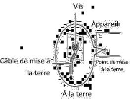
Consignes de sécurité électrique
•Avant d’allumer l’appareil, reliez le câble de mise à la terre de l’équipement à la terre.
•Une bonne mise à la terre (connexion à la terre) est très importante pour protéger l’équipement contre les effets néfastes du bruit externe et réduire les risques d’électrocution en cas de foudre.
•Pour désinstaller l’équipement, débranchez le câble de mise à la terre après avoir éteint l’appareil.
•Un câble de mise à la terre est requis et la zone reliant les sections du conducteur doit faire plus de 4 mm2 ou 10 AWG.
Procédure de mise à la terre pour source d’alimentation CC Procédure de mise à la terre pour source d’alimentation CC
•Desserrez la vis du terminal de mise à la terre.
•Branchez le câble de mise à la terre à la terre.
•L’appareil de protection pour la source d’alimentation CC doit fournir 30 A de courant.
Cet appareil de protection doit être branché à la source d’alimentation avant l’alimentation CC.
Version |
Descriptions |
0.2 |
Add the BIOS menu information |
1.0 |
Official release |
1.1 |
Modified SSD and CF card installations |

Table of Contents
Chapter 1: Introduction |
6 |
System Specifications |
6 |
Package Contents |
7 |
Optional Accessories |
7 |
Front Panel Features |
8 |
Rear Panel Features |
9 |
Chapter 2: Motherboard Information |
10 |
Block Diagram |
10 |
Motherboard Layout |
11 |
Jumper Settings & Connector Pinouts |
12 |
Chapter 3: Hardware Setup |
16 |
Preparing the Hardware Installation |
16 |
Installing the System Memory |
16 |
Installing Disk Drive |
16 |
Installing the CompactFlash Card |
17 |
Installing the Mini-PCIe Card |
17 |
Installing FW-7525 on the Wall |
18 |
Installing FW-7525 on a Rack |
19 |
Chapter 4: BIOS Settings |
21 |
Appendix A: Programming Watchdog Timer |
36 |
Appendix B: Setting up Console Redirections |
36 |
Appendix C: Programming Generation 2 LAN Bypass |
37 |
Appendix D: Installing Intel QuickAssist Software for Linux |
39 |
Appendix E: Terms and Conditions |
40 |
Chapter 1:
Introduction
Thank you for choosing Lanner FW-7525. FW-7525 is a fanless desktop network security system utilizing the cutting edge capabilities of the Intel Rangeley platform (Based on Intel Atom C2000 series 2-core/4-core CPU, System-On-Chip solution). The Rangeley platform
is built-in Intel QuickAssist Crypto acceleration, it targets at Entry-level UTM, Firewall, VPN, IPS and WAN optimization applications in SMB environment. The system built-in 4 or 6 GbE LAN ports, 1 x Non-ECC DDR3 1333/1600 DIMMs, and 36/60 W power adapter.
Features:
•Intel Atom C2358/C2518/C2558 CPU built-in Intel QuickAssist Crypto acceleration
•Fanless design
•Rangeley Platform
•Fanless design, compact form factor
•Intel AES-NI new instructions, improves security without slowing response times
•Support up to 8 GB DDR3 Memory
•Intel i210AT LAN controller
•Support Gen.2 LAN Bypass function (model A, C, and D only))
•Intel Virtualization Technology
Intel C2000 series processor comes with an enhanced cryptographic/content processing acceleration via integrated Intel®QuickAssist Integrated Accelerator with the following instructions:
–Bulk Encryption: AES, DES, 3DES, RC4
–Hash: SHA-1, MD5; SHA-2 (SHA-224, SHA-256, SHA384, SHA-512);
–Authentication: HMAC, AES-XCBC, AES-CCM, and AES-GCM
–Public Key Exchanges: RSA, DH, DSA, ECC
System Specifications
Form Factor
Platform |
Processor Options |
|
|
|
|
BIOS |
|
|
System |
Technology |
|
|
||
Memory |
|
|
Max. Capacity |
||
|
Socket |
|
|
|
|
OS Support |
|
|
Storage |
HDD/SSD Bays |
|
CompactFlash |
||
|
||
|
Ethernet Ports |
|
|
Bypass |
|
Networking |
|
|
Controllers |
||
|
||
|
|
|
|
Ethernet Modules |
|
|
Management Port |
|
|
Reset Button |
|
|
|
|
|
Console |
|
I/O Interface |
USB |
|
|
IPMI via OPMA |
|
|
slot |
|
|
Display |
|
Expansion |
PCIe |
|
PCI |
||
|
||
Cooling |
Processor |
|
System |
||
|
||
|
Temperature, |
|
|
ambient operating |
|
Environmental |
/ storage |
|
Humidity (RH), |
||
Parameters |
||
ambient operating |
||
|
||
|
/ ambient non- |
|
|
operating |
|
|
LCD Module |
|
Miscellaneous |
Watchdog |
|
Internal RTC with |
||
|
||
|
Li Battery |
|
Physical |
Dimensions |
|
(WxHxD) |
||
Dimensions |
||
Weight |
||
|
||
Power |
Type/Watts |
|
|
||
|
Input |
Desktop
2-core Intel® Atom Processor C2358 2-core, C2518 4-core, or C2558 2.4GHz 4-core CPU (Codenamed “Rangeley”)
AMI BIOS 16MB
Single Channel Non-ECC DDR3 1333/1600 MHz,
1.5 V
8 GB
1 x 204-pin SO-DIMM Linux Kernel 2.6 or above
1 x 2.5” SSD kit
1 x Type II CompactFlash
4 or 6 x GbE RJ45 onboard
1 pairs Generation 2 (on
model FW-7525A/C only) 2 x Intel i210AT, 4 x
Marvell 88E1543
N/A
N/A
1 x reset button Software reset by default
1 x RJ45
2 x USB 2.0
N/A
N/A
1 x Mini-PCIe
N/A
Fanless
Fanless
0 ~ 40º C / -20~70º C
5~90%, non-condensing / 5~95%, non-condensing
N/A
Yes
Yes
177 x 44 x 145.5 mm
1.2 kg
36W/60W Power Adapter
100~240V@50~60Hz

Certifications/Compliance |
CE Class B, FCC Class B, |
|
RoHS |
||
|
Ordering Information
Fanless Network Security Appliance with
FW-7525A Intel® AtomTM processor C2358 (Codenamed “Rangeley”), 6 GbE LAN ports with
Gen.2 Bypass, 36W power adapter
Fanless Network Security Appliance with
FW-7525B Intel® AtomTM processor C2358 (Codenamed “Rangeley”), 4 GbE LAN ports
without Bypass, 36W power adapter
Fanless Network Security Appliance with
FW-7525C Intel® AtomTM processor C2518 (Codenamed “Rangeley”), 6 GbE LAN ports with
Gen.2 Bypass, 60W power adapter
Fanless Network Security Appliance with
FW-7525D Intel® AtomTM processor C2558 (Codenamed “Rangeley”), 6 GbE LAN ports with
Gen.2 Bypass, 60W power adapter
Package Contents
Your package contains the following items:
•FW-7525 Network Security Platform
•US standard Power cable
•1 console cable
•Drivers and user’s manual CD.
•36W/60W power adaptor
•1 – screws pack
Optional Accessories
The system has a variety of optional accessories, visit the following website for more information.
http://www.lannerinc.com/products/x86-network- appliances/rackmount/fw-7525

Front Panel Features
F1 |
|
F4 |
F2 |
F3 |
LAN1 |
LAN2 |
|
|
Intel i210AT |
Intel i210AT |
|
|
|
LAN3 |
LAN4 |
|
|
Marvell 88E1543 |
Marvell 88E1543 |
|
|
|
LAN5 |
LAN6 |
|
|
Marvell 88E1543 |
Marvell 88E1543 |
|
|
(bypass pair) |
|
F1 Console Port
RJ-45 console port: it is used to connect to a computer terminal for diagnostic or configuration purpose.
F2 SSD/Status/Power LED
F3 Two USB 2.0 Ports
F4 Ethernet Ports (LAN1: PXE-capable Port, LAN5-LAN6: bypass pair*)
LAN3~LAN6 GbE ports are provided by Marvell 88E1543 and LAN1~LAN2 are provided by Intel i210AT. LAN1 is capable of Preboot eXecution Environment (PXE) (This feature needs to be enabled or disable in the BIOS; the default is disabled). One pair (LAN5-LAN6) can be configured as LAN Bypass by using Lanner Gen2 Bypass technology when failure events occur. This feature can be enabled dynamically with a watch dog timer. Refer to your User’s Manual CD for sample implementation of this feature.
 Note:
Note:
1.The LAN bypass functionality is only available on model FW-7525A/C/D
2.The FW-7525B only has 4 Ethernet ports.
Rear Panel Features
R1 |
R2 |
|||
|
R3 |
|||
|
|
|
||
|
|
|
|
|
|
|
|
|
|
|
|
|
|
|
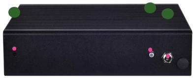
R1 Reset Switch
The reset switch can be used to reboot the system without turning off the power.
R2 ATX Power-on button with LEDs
Standby mode in Red; Power-on mode in Green
R3 Power-in Socket
The system requires 36W/60W power.

Chapter 2:
Motherboard Information
Block Diagram
The block diagram depicts the relationships among the interfaces or modules on the motherboard. Please refer to the following figure for your motherboard’s layout design.

Motherboard Layout
The motherboard layout shows the connectors and jumpers on the board. Refer to the following picture as a reference of the pin assignments and the internal connectors.
FAN1
SPIROM1
|
|
|
|
|
|
|
|
|
|
|
|
CF1 |
|||||
COMB2 |
|
|
|
|
|
|
|
|
|
|
|||||||
|
|
|
|
|
|
|
|
|
|||||||||
|
|
|
|
|
|
|
|
|
|
|
|
SATA6G_1 |
|||||
|
|
|
|
|
|
|
|
|
|
|
|
|
|
||||
|
|
|
|
|
|
|
|
|
|
|
|
LPC1 |
|||||
MPCIE1 |
|
||||||||||||||||
|
|
|
|
|
|
|
|
|
|
|
|
|
|
|
|
||
USB2 |
|
|
|
|
|
PKMB1 |
|||||||||||
|
|
|
|
|
|
|
|
|
|
|
|
|
|
|
|
|
|
|
|
|
|
|
|
|
|
|
|
|
|
|
J20 |
||||
|
|
|
|
|
|
|
|
|
|
|
|
|
|
JBAT1 |
|||
|
|
|
|
|
|
|
|
|
|
|
|
|
|
||||
|
|
|
|
|
|
|
|
|
|
|
|
|
|
|
|
|
|
|
|
|
|
|
|
|
|
|
|
|
|
PS4P1 |
|||||
|
|
|
|
|
|
|
|
|
|
|
|
J4 |
|||||
|
|
|
|
|
|
|
|
|
|
|
|
|
GPIO1 |
||||
|
|
|
|
|
|
|
|
|
|
|
|
|
|
|
|
|
|
|
|
|
|
|
|
|
|
|
|
|
|
|
|
|
|
|
|
|
|
|
|
|
|
|
|
|
|
|
|
|
|
|
|
|
|
|
|
|
|
|
|
|
|
|
|
COM1 |
|
LAN6 |
LAN5 |
LAN4 |
LAN3 |
LAN2 |
LAN1 |
USB1 |
|
|
|||||||
Jumper Settings & Connector Pinouts
Fan Connectors(FAN1 ): The 5-pin connector is for connecting the CPU fan.
Pin No. |
Signal |
1 |
PWM |
|
|
2 |
NC |
|
|
3 |
TACH |
|
|
4 |
P12V |
|
|
5 |
GND |
|
|
Keyboard and Mouse Connector (PKMB1)
|
1 |
|
|
|
2 |
|
|
|
|
|
|
||
|
7 |
|
|
|
8 |
|
|
|
|
|
|
||
|
|
|
|
|
||
|
|
|
|
|
||
|
|
|
|
|
||
|
|
|
|
|
|
|
Pin No. |
Signal |
Pin No. |
Signal |
|||
1 |
+P5V_KM |
2 |
MS_L_CLK |
|||
3 |
MS_L_DAT |
4 |
NC |
|||
5 |
KB_L_DAT |
6 |
NC |
|||
7 |
GND |
8 |
KB_L_CLK |
|||
COM Port 2 (COMB2): The internal COM port
|
1 |
|
|
|
2 |
|
|
|
|
|
|
||
|
9 |
|
|
|
10 |
|
|
|
|
|
|
||
|
|
|
|
|
||
|
|
|
|
|
||
|
|
|
|
|
|
|
Pin No. |
Signal |
Pin No. |
Signal |
|||
1 |
NDCD2- |
2 |
NDSR2- |
|||
3 |
NSIN2 |
4 |
NRTS2- |
|||
5 |
NSOUT2 |
6 |
NCTS2- |
|||
7 |
NDTR2- |
8 |
NRI2- |
|||
9 |
COMGND2 |
10 |
|
|||
USB Pin Header (USB2): It is for connecting the USB module cable. It complies with USB2.0 and support up to 480 Mbps connection speed.
|
1 |
|
|
|
2 |
|
|
|
|
|
|
||
|
9 |
|
|
|
10 |
|
|
|
|
|
|
||
|
|
|
|
|
||
|
|
|
|
|
||
|
|
|
|
|
|
|
Pin No. |
Signal |
|
Pin No. |
Signal |
||
1 |
+P5V_USB2_L |
2 |
NC |
|||
3 |
USB2_SB_L_DN |
4 |
NC |
|||
5 |
USB2_SB_L_DP |
6 |
NC |
|||
7 |
GND |
8 |
GND |
|||
9 |
GND |
10 |
Key ping |
|||
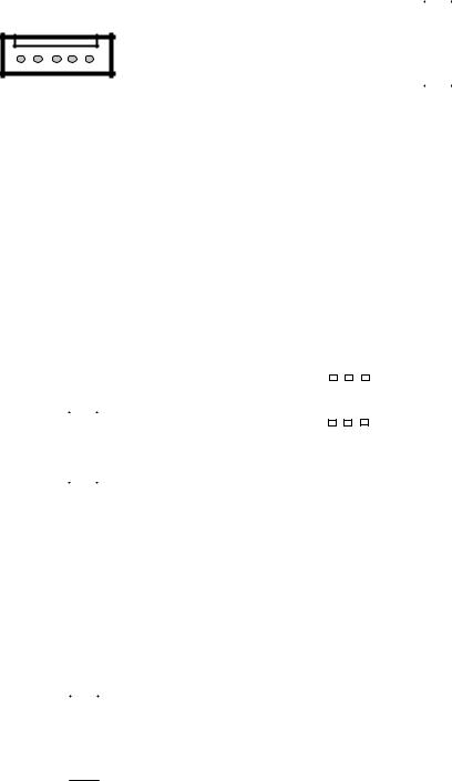
Dual USB 2.0 Ports (USB1): This provides two USB 2.0 ports on the front panel.
|
|
|
|
|
|
|
Pin No. |
Signal |
|
|
|
|
|
|
|
1 |
+P5V_USB0_L |
|
|
|
|
|
|
|
2 |
USB0_SB_L_DN |
|
|
|
|
|
|
|
||
|
|
|
|
|
|
|
3 |
USB0_SB_L_DP |
5 |
6 |
7 8 |
|
|
||||
|
|
|
|
|
|
|
4 |
GND |
|
|
|
|
|
|
|
||
|
|
|
|
|
|
|
5 |
+P5V_USB0_L |
|
|
|
|
|
|
|
||
|
|
|
|
|
|
|
||
1 |
2 |
3 |
4 |
|
|
6 |
USB1_SB_L_DN |
|
|
|
|
|
|
|
|
||
|
|
|
|
|
|
|
7 |
USB1_SB_L_DP |
|
|
|
|
|
|
|
8 |
GND |
Console Port (COM1): The external COM port with RJ45 connector
Pin No. |
Signal |
Pin No. |
Signal |
1 |
LNRTSA# |
5 |
GND |
2 |
LNDTRA# |
6 |
LNSINA |
3 |
LNSOUTA |
7 |
LNDSRA# |
4 |
GND |
8 |
LNCTSA# |
GPIO Output Pin (GPIO1): Theses pins can be used to write to an internal register to control the GPIO output pin state.
Clear CMOS jumper (JBAT1): It is for clearing the CMOS memory and system setup parameters by erasing the data stored such as the system passwords in the CMOS RAM.
|
2 |
|
|
|
|
|
|
|
10 |
|
|
|
|
|
|
|
|
|
|
||
|
1 |
|
|
|
|
|
|
|
9 |
|
|
|
|
|
|
|
|
|
|
||
|
|
|
|
|
||||||
Pin No. |
Signal |
|
Pin No. |
Signal |
||||||
1 |
SIO_GP20 |
|
2 |
|
SIO_GP21 |
|||||
3 |
SIO_GP46 |
|
4 |
|
SIO_GP47 |
|||||
5 |
SIO_GP53 |
|
6 |
|
SIO_GP54 |
|||||
7 |
SIO_GP56 |
|
8 |
|
SIO_GP57 |
|||||
9 |
P5V |
|
10 |
GND |
||||||
|
|
|
|
Pin No. |
Signal |
|
|
|
|
|
1 |
VBAT |
|
|
|
|
|
2 |
PCH_RTCRST_N |
|
1 2 3 |
|
|||||
3 |
GND |
|||||
|
|
|
|
|||
CompactFlash Connector (CF1): It is for connecting a Compact Flash card to be served as your system’s storage. The connector is a CF Type II slot which could fit both CF Type I or CF Type II cards.
SPI-ROM Update Connector (SPIROM1): It is for updating the SPI Flash soldered on board for service and repair purposes.
1 2
|
9 |
|
|
10 |
|
||
|
|
|
|
|
|
|
|
|
|
|
|
|
|
|
|
Pin No. |
Signal |
Pin No. |
Signal |
||||
1 |
SPI_HOLD0_L |
2 |
NC |
||||
3 |
PMU_AVN_SPI_R_ |
4 |
V_3P3_SPI |
||||
|
CS0 |
|
|
|
|
||
5 |
PMU_AVN_SPI_MISO |
6 |
NC |
||||
7 |
NC |
8 |
PMU_AVN_SPI_R_CLK |
||||
9 |
GND |
10 |
PMU_AVN_SPI_R_MOSI |
||||
LPC I/O bus (It can also be called Port 80) (LPC1): It is a proprietary connector for connecting
a checkpoint device to output checkpoints throughout booting and Power-On Self Test (POST) to indicate the task the system is currently executing.
1 2
|
9 |
|
|
10 |
|
||
|
|
|
|
|
|
|
|
|
|
|
|
|
|
|
|
Pin No. |
Signal |
|
Pin No. |
Signal |
|||
1 |
CLK_33M_P80 |
2 |
LPC_AD1 |
||||
3 |
PLTRST_PORT80_N |
4 |
LPC_AD0 |
||||
5 |
LPC_FRAME_N |
6 |
P3V3 |
||||
7 |
LPC_AD3 |
8 |
Key ping |
||||
9 |
LPC_AD2 |
10 |
GND |
||||
|
|
50 |
CF1 |
26 |
|
|
|||
|
|
|
|
|
|
|
|
|
|
|
|
|
|
|
|
|
|
|
|
|
|
|
|
|
|
|
|
|
|
|
|
|
|
|
|
|
|
|
|
|
|
25 |
|
1 |
|
|
|
||
|
|
|
|
|
|||||
Pin No. |
Signal |
Pin No. |
|
Signal |
|||||
1 |
|
|
GND |
26 |
|
DET1 |
|||
2 |
|
CF_DD3 |
27 |
CF_DD11 |
|||||
3 |
|
CF_DD 4 |
28 |
CF_DD 12 |
|||||
4 |
|
CF_DD 5 |
29 |
CF_DD 13 |
|||||
5 |
|
CF_DD 6 |
30 |
CF_DD 14 |
|||||
6 |
|
CF_DD 7 |
31 |
CF_DD 15 |
|||||
7 |
|
-CF_DCS0 |
32 |
-CF_DCS1 |
|||||
8 |
|
|
GND |
33 |
|
CF_VS1 |
|||
9 |
|
|
GND |
34 |
CF_DIOR_N |
||||
10 |
|
|
GND |
35 |
CF_DIOW_N |
||||
11 |
|
|
GND |
36 |
|
WE# |
|||
12 |
|
|
GND |
37 |
CF_IDEIRQ |
||||
13 |
|
VCC_CF |
38 |
|
VCC_CF |
||||
14 |
|
|
GND |
39 |
MST_SLV |
||||
15 |
|
|
GND |
40 |
|
CF_VS2 |
|||
16 |
|
|
GND |
41 |
CF_IDERST_N |
||||
17 |
|
|
GND |
42 |
CF_IORDY |
||||
18 |
|
CF_DA2 |
43 |
CF_DMARQ |
|||||
19 |
|
CF_DA 1 |
44 |
CF_DDACK_N |
|||||
20 |
|
CF_DA 0 |
45 |
CFACT_N |
|||||
21 |
|
CF_DD0 |
46 |
CF_PDIAG |
|||||
22 |
|
CF_DD 1 |
47 |
|
CF_DD 8 |
||||
23 |
|
CF_DD 2 |
48 |
|
CF_DD 9 |
||||
24 |
|
|
GND |
49 |
CF_DD 10 |
||||
25 |
|
|
DET2 |
50 |
|
GND |
|||
 Loading...